EP2368832B1 - Damping or prevention of vibrations in industrial trucks - Google Patents
Damping or prevention of vibrations in industrial trucks Download PDFInfo
- Publication number
- EP2368832B1 EP2368832B1 EP20110159184 EP11159184A EP2368832B1 EP 2368832 B1 EP2368832 B1 EP 2368832B1 EP 20110159184 EP20110159184 EP 20110159184 EP 11159184 A EP11159184 A EP 11159184A EP 2368832 B1 EP2368832 B1 EP 2368832B1
- Authority
- EP
- European Patent Office
- Prior art keywords
- load
- lifting frame
- receiving section
- freedom
- industrial truck
- Prior art date
- Legal status (The legal status is an assumption and is not a legal conclusion. Google has not performed a legal analysis and makes no representation as to the accuracy of the status listed.)
- Active
Links
Images


Classifications
-
- B—PERFORMING OPERATIONS; TRANSPORTING
- B66—HOISTING; LIFTING; HAULING
- B66F—HOISTING, LIFTING, HAULING OR PUSHING, NOT OTHERWISE PROVIDED FOR, e.g. DEVICES WHICH APPLY A LIFTING OR PUSHING FORCE DIRECTLY TO THE SURFACE OF A LOAD
- B66F9/00—Devices for lifting or lowering bulky or heavy goods for loading or unloading purposes
- B66F9/06—Devices for lifting or lowering bulky or heavy goods for loading or unloading purposes movable, with their loads, on wheels or the like, e.g. fork-lift trucks
- B66F9/075—Constructional features or details
- B66F9/12—Platforms; Forks; Other load supporting or gripping members
- B66F9/125—Platforms; Forks; Other load supporting or gripping members rotatable about a longitudinal axis
-
- B—PERFORMING OPERATIONS; TRANSPORTING
- B66—HOISTING; LIFTING; HAULING
- B66F—HOISTING, LIFTING, HAULING OR PUSHING, NOT OTHERWISE PROVIDED FOR, e.g. DEVICES WHICH APPLY A LIFTING OR PUSHING FORCE DIRECTLY TO THE SURFACE OF A LOAD
- B66F9/00—Devices for lifting or lowering bulky or heavy goods for loading or unloading purposes
- B66F9/06—Devices for lifting or lowering bulky or heavy goods for loading or unloading purposes movable, with their loads, on wheels or the like, e.g. fork-lift trucks
- B66F9/075—Constructional features or details
- B66F9/07545—Overhead guards
-
- B—PERFORMING OPERATIONS; TRANSPORTING
- B66—HOISTING; LIFTING; HAULING
- B66F—HOISTING, LIFTING, HAULING OR PUSHING, NOT OTHERWISE PROVIDED FOR, e.g. DEVICES WHICH APPLY A LIFTING OR PUSHING FORCE DIRECTLY TO THE SURFACE OF A LOAD
- B66F9/00—Devices for lifting or lowering bulky or heavy goods for loading or unloading purposes
- B66F9/06—Devices for lifting or lowering bulky or heavy goods for loading or unloading purposes movable, with their loads, on wheels or the like, e.g. fork-lift trucks
- B66F9/075—Constructional features or details
- B66F9/08—Masts; Guides; Chains
-
- B—PERFORMING OPERATIONS; TRANSPORTING
- B66—HOISTING; LIFTING; HAULING
- B66F—HOISTING, LIFTING, HAULING OR PUSHING, NOT OTHERWISE PROVIDED FOR, e.g. DEVICES WHICH APPLY A LIFTING OR PUSHING FORCE DIRECTLY TO THE SURFACE OF A LOAD
- B66F9/00—Devices for lifting or lowering bulky or heavy goods for loading or unloading purposes
- B66F9/06—Devices for lifting or lowering bulky or heavy goods for loading or unloading purposes movable, with their loads, on wheels or the like, e.g. fork-lift trucks
- B66F9/075—Constructional features or details
- B66F9/12—Platforms; Forks; Other load supporting or gripping members
- B66F9/14—Platforms; Forks; Other load supporting or gripping members laterally movable, e.g. swingable, for slewing or transverse movements
- B66F9/147—Whole unit including fork support moves relative to mast
- B66F9/148—Whole unit including fork support moves sideways
Definitions
- the present invention relates to an industrial truck with a lifting frame, on which a load-receiving section is mounted so as to be movable vertically, and a method for damping or preventing vibrations in such industrial trucks.
- a generic industrial truck comprises a lifting frame on which a load-receiving section is mounted so as to be movable vertically.
- the term "load-receiving section" is to be understood broadly in the present document and can comprise all components which are arranged so as to be movable vertically on the lifting frame.
- a load fork and a load fork carrier typically belong to the load-receiving section.
- the load-receiving section further comprises a driver's station which is moved vertically on the lifting frame together with the load.
- Such industrial trucks are known under the term "man-up equipment" or vertical order picker.
- WO 2006/137761 A1 An example for a lifting truck is disclosed in the patent document WO 2006/137761 A1 which relates to a system for controlling the tilting of a load-carrying implement of a moveable work machine.
- the implement of the work machine can be tilted about a first axis by a first tilting means and about a second axis by a second means for side tilting.
- the work machine comprises a control unit for controlling the operation of the first tilting means and the second tilting means.
- the load-receiving apparatus comprises a load-receiving fork which can be moved in three directions by means of linear guides which are associated with corresponding driving means. Together with the load-receiving fork the linear guides are disposed at an axle which is pivotally mounted to a bracket by a bearing and which can be driven by driving means in order to perform a fine positioning of the load-receiving fork.
- the fork lift comprises a backing frame and a fork.
- the fork is pivotally connected to a crossbar by a horizontal axle.
- the crossbar is connected to the backing frame by a first connection by means of two location bars and a bracket and by a second connection by means of a leaf spring for generating vertical resident forces.
- the leaf spring is connected at two opposite sides to the backing frame and by a central clamp to the crossbar. Due to these connections, shocks in vertical directions between the fork and the backing frame are absorbed when loads are transported.
- DE 32 10 951 C2 the problems of lifting frame vibrations in the receiving and depositing of loads or respectively of load carriers, e.g. pallets, are described.
- reflex marks are applied to the shelf surfaces or to the pallets, said reflex marks being detected by a sensor fastened to the load fork, in order to determine the relative position of the shelf or pallet and load fork.
- the load fork can be aligned automatically for receiving or depositing the load.
- the actual function of the reflex mark and of the sensor consists in that the industrial truck can transport, receive and deposit loads automatically without a driver.
- DE 32 10 951 with the aid of the reflex mark and the sensor in addition the phase and amplitude of the vibrations of the lifting frame can be measured in the direction of travel of the industrial truck.
- the load fork of the described industrial truck is adjustable relative to the lifting frame horizontally in the direction of travel and is provided with a corresponding drive means, in order to move the load fork forward and backward - in relation to the direction of travel of the industrial truck - on depositing or receiving loads.
- DE 32 10 951 suggests actuating the drive means, which are present anyhow, between the load fork and the lifting frame so that the vibrations of the load fork are damped.
- the drive means is regulated as a controlling element of a closed-loop control so that the sensor on the load fork is brought close to a desired zero position in relation to the reflex mark.
- a method which is similar in conceptual design for the damping of vibrations of the lifting frame of an industrial truck is known from applications DE 10 2007 015 488 , DE 10 2007 024 817 A1 and EP 1 975 114 A1 , which are related with regard to content and belong to the same patent family.
- the lifting frame is able to be moved forward and back as a whole in the direction of travel.
- these applications suggest functionalizing the drive, which is present anyhow, for the horizontal displacement of the lifting frame in the direction of travel as a controlling element in a regulator circuit, with which vibrations of the lifting frame are to be regulated to zero.
- a sensor by which the amplitude of the vibration of the lifting frame can be measured, serves as measurement indicator for the regulator, this sensor being in actual terms a strain gauge or an acceleration sensor on the lifting frame.
- the invention is therefore based on the problem of providing an industrial truck and a method in which vibrations in the lifting frame can be efficiently damped or even prevented entirely.
- the load-receiving section has at least one degree of movement freedom in relation to the lifting frame, which lies in a plane perpendicular to the main direction of travel and has at least one horizontal component.
- means are provided for damping or preventing vibrations in the relative position of the load-receiving section and lifting frame along this degree of freedom.
- an additional degree of movement freedom is created between the load-receiving section and the lifting frame.
- This degree of movement freedom is an additional degree of freedom which is not provided for the intended operation of the industrial truck and serves for a decoupling of the load-receiving section and lifting frame.
- this additional degree of freedom allows for the load-receiving section and the lifting frame to vibrate against each other.
- vibrations in the relative position of the load-receiving section and lifting frame which could not occur at all without this additional degree of freedom, are then dissipated by said means for damping or preventing vibrations.
- the vibrational energy of the total system of lifting frame and load-receiving section which is unavoidably produced during operation, is transferred into the newly created degree of freedom and can be dissipated in this degree of freedom by the damping means, so that the vibration energy can be efficiently removed from the total system.
- the additional degree of freedom is perpendicular to the main direction of travel of the vehicle and has at least one horizontal component, whereby vibrations can be efficiently damped transversely to the direction of travel.
- vibrations transversely to the direction of travel constitute a particular problem.
- Transverse vibrations can be produced for example when the industrial truck travels over an unevenness in the ground.
- these manoeuvres can already be carried out so that only few vibrations occur at all in the direction of travel.
- This predictability does not exist in the main source of transverse vibrations, namely unevennesses in the ground. Therefore, transverse vibrations can occur in a surprising manner at any time and also can scarcely be avoided by careful operation.
- Transverse vibrations therefore constitute a particular problem, because they harbour the risk that the lifting frame strikes laterally against the shelves.
- small aisle widths are selected between the shelves, which exceed the vehicle width only by a safety distance of 100 mm on both sides. With such small distances between the shelves and the vehicle, collisions with the lifting frame can easily occur through transverse vibrations.
- Said motion degree of freedom can be a horizontal translatory degree of freedom, a rotational degree of freedom, swing degree of freedom or a combination of two of these or all these.
- the "swing degree of freedom” designates here a degree of freedom which is produced when the load-receiving section is articulated on the lifting frame via two parallel pendulum rods and therefore corresponds to a displacement along a circular path, without the load-receiving section itself being rotated. More precise explanations concerning the different degrees of freedom are given below with reference to the example embodiments.
- the means for damping and preventing vibrations comprise active, semi-active and/or passive means, which are suitable for producing a force or a moment between the lifting frame and the load-receiving section, which has at least one component along said at least one degree of movement freedom.
- a restoring element in particular a spring, is provided which counteracts an elongation between the lifting frame and the load-receiving section along the degree of freedom.
- a damping element is preferably provided, which damps relative movements of the load-receiving section and the lifting frame.
- a simple, passive spring/damper combination can be provided between the lifting frame and the load-receiving section.
- the vibrations which would be produced in the case of a rigid connection of lifting frame and load-receiving section are converted into a damped relative vibration or oscillation between lifting frame and load-receiving section, so that the vibrational energy in this additional degree of freedom is dissipated effectively and quickly by the damping element.
- the restoring force or the restoring moment of the restoring element and/or the damping characteristic of the damping element can be adapted to one or more operating parameters, in particular to one or more of the following operating parameters: speed of travel, lift height, loading status, deformation status of the lifting frame and/or acceleration status of the lifting frame or of the load-receiving section.
- the restoring element and the damping element per se are passive elements, because they do not have any drive means, their characteristics can be adapted as a function of the described operating parameters, in order to optimize the damping effect.
- the parameters of bending or deformation status or acceleration status are dynamic parameters, to which the restoring- and/or damping element can be adapted in real time, in order to effectively damp or entirely prevent vibrations.
- Semi-active elements in the sense of the present disclosure are elements which are able to be controlled electronically, but do not have their own drive means.
- At least one actuator is provided, which is suited to produce a force or moment between the lifting frame and the load-receiving section, which has at least one component along said at least one degree of movement freedom, and a control device and/or regulating device is provided for controlling or regulating the actuator such that vibrations in the relative position of load-receiving section and lifting frame are damped.
- the actuator can be an electromechanical, a pneumatic or a hydraulic controlling element.
- the damping effect can be further increased compared with a construction which is based only on passive or semi-active damping and restoring elements.
- such an actuator can be provided as a supplement to the passive or semi-active restoring or damping means.
- the controlling or regulating device is connected with at least one sensor for detecting the relative position of the lifting frame and load-receiving section.
- the set value of the regulating device corresponds to a predetermined relative position of the lifting frame and load-receiving section.
- the set value or a further set value of the regulating device can correspond to a horizontal position of the load-receiving section. Thereby, it becomes possible to keep the load-receiving section in a horizontal state, even when the industrial truck travels over sloping ground.
- the controlling or regulating device is coupled with at least one sensor for detecting the deformation status of the lifting frame, for example a strain gauge or a piezoelectric sensor. Additionally or alternatively, the controlling or regulating device is preferably coupled with at least one acceleration sensor which is arranged on the lifting frame and/or on the load-receiving section. Preferably, the controlling or regulating device is further arranged to calculate the actuating variable for the actuator, taking into consideration one or more of the following operating parameters: speed of travel, lift height, loading status, bending or deformation status of the lifting frame and/or acceleration status of the lifting frame or of the load-receiving section.
- several position- or acceleration sensors are arranged on the load-receiving section and the controlling or regulating device is adapted to calculate one or several control values as a function of the measured values of the position or acceleration sensors so that the load-receiving section carries out a pure translation movement.
- the aim of such a regulation is a status in which the load-receiving section is moved independently of the movement of the chassis of the industrial truck and of the lifting frame, as if it travelled along an imaginary ceiling rail.
- This type of damping is also designated as "skyhook" damping. Such a skyhook damping is only conceivable, however, because according to the invention one or several additional degrees of movement freedom are created between the load-receiving section and the lifting frame.
- said at least one degree of freedom is able to be locked, so that a relative movement is prevented between the lifting frame and the load-receiving section in the locked state.
- a locking is advantageous for example in the load transfer processes at the target position, in order to ensure that no relative movement is produced by the receiving or depositing of the load.
- a vertically movable auxiliary carrier is provided on the lifting frame, on which the load-receiving section is fastened movably in the direction of said at least one degree of freedom.
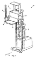
- Fig. 1 shows a perspective view of an industrial truck 10 with a lifting frame 12 which is telescopically extendable, on which a driver's station 14, a load fork carrier 16 and a load fork 18 are fastened, which is partially covered in the figures by a pallet 20.
- a driver's station 14 Such an industrial truck with a liftable driver's station is also designated as "man-up equipment”.
- the driver's station 14, the load fork carrier 16 and the load fork 18 in combination are referred to as "load-receiving section" 22 below.
- the main direction of travel of the industrial truck 10 is marked by the arrow 24.
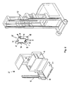
- Fig. 2 shows an exploded illustration of the industrial truck of Fig. 1 according to a first embodiment of the invention.
- an auxiliary carrier 26 is provided which is mounted so as to be movable vertically over guide rollers 28 on the lifting frame 12.
- the load-receiving section 22 can carry out a pendulum-like movement transverse to the direction of travel, in which the load-receiving section 22 is, however, always guided parallel to the lifting frame 12, which as a result corresponds to a displacement along a circular path.
- a position sensor 32 is provided on the auxiliary carrier 26 and on the load-receiving section 22, more precisely on the driver's station 14. The relative displacement or elongation between the auxiliary carrier 26 (or lifting frame 12) and the load-receiving section 22 then results from the comparison of the measured absolute position information.
- a spring/damper combination 34 is fastened by a first end C on the auxiliary carrier 26 and by a second end at a point D on the load-receiving section 22, which can not be seen, however, in the exploded illustration of Fig. 2 .
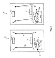
- a schematic illustration of the auxiliary carrier 26 of Fig. 2 is shown in the state of rest, and in Fig. 3b in the displaced or elongated state.
- the points A and C, which are fixed on the auxiliary carrier 26, are illustrated in black and the points B and D, which are fixed on the load-receiving section 22, are illustrated in white.
- the spring/damper element 34 was illustrated functionally as a combination of spring element 34a and damper element 34b arranged in parallel.
- vibrations of the lifting frame 12 often build up, which may lead to an oscillating movement of the load-receiving section 22.
- These oscillating movements are all the greater, the higher the load-receiving section 22 has been moved upwards on or by the lifting frame 12.
- These oscillating movements are felt to be unpleasant by the driver in the driver's station 14 and harbour the danger that the load-receiving section 22 for example collides with storage shelves. This danger exists in particular in the case of vibrations transversely to the direction of travel.
- These vibrations usually still last for a certain time after the industrial truck has been stopped for example for a load transfer. This means that between the stopping and the dying down of the vibrations, one must wait for the load transfer, so that this time elapses unproductively.
- the vibrations which in the case of a rigid connection between lifting frame 12 and load-receiving section 22 would have lead to the described oscillating movement, are - at least with respect to their component in transverse direction - transferred to the additional swing degree of freedom provided by the auxiliary carrier 26.
- a relative vibration occurs along the additional degree of freedom between lifting frame 12 and load-receiving section 22.
- the relative deviation or elongation between lifting frame 12 and load-receiving section 22 can be determined along the pendular or swing degree of freedom.
- a purely passive damping device as is formed by a simple spring/damper element 34, there is, however, no need yet for the absolute position information of the individual sections (auxiliary carrier 26 or load-receiving section 22) nor for the relative position information which can be derived therefrom.
- the purely passive damping mechanism can, however, be supplemented or replaced by semi-active or active elements.
- the spring/damper combination 34 it is e.g. possible to adapt the restoring force of the spring 34a and/or the damping characteristic of the damping element 34b to one or more operating parameters. Suitable operating parameters for this are the speed of travel of the industrial truck 10, the lift height and the loading status of the load-receiving section 22. For each of these operating parameters, the ideal restoring force and damping characteristic can be determined in advance and then set upon operation.
- the degree of damping of a damping element can be controlled very rapidly by electrical actuation of a bypass valve, so that it can be adapted optimally and in real time to an acceleration status of the lifting frame 12 or of the load-receiving section 22 in order to produce as effective a damping as possible.
- acceleration sensors can be provided (not shown) on the lifting frame 12 and/or on the load-receiving section 22.
- the degree of damping of the damping element 34b is a function of the bending or deformation status of the lifting frame 12, which can be determined for example by means of strain gauges or piezoelectric sensors.
- the state of strain of the lifting frame is valuable information, because the movement resulting from the bending can already be forecast therefrom. It is therefore possible to actuate the damping element 34b as a function of these operating parameters or current system statuses in a manner which results in a more efficient damping of the vibration than is possible with purely passive elements.
- Such actuatable elements which do not have any drive means themselves are designated herein as semi-active elements.
- At least one actuator can also be provided, which is suitable for generating a force between the lifting frame 12 and the load-receiving section 22 having at least one component along the swing degree of freedom of Fig. 2 , and which is connected with a controlling device or a regulating device (not shown), in order to control or regulate the actuator such that the vibrations in the relative position of load-receiving section 22 and lifting frame 12 are damped or prevented.
- the relative position between the auxiliary carrier 26 and the load-receiving section 22 can be determined by means of the position sensors 32, and the deviation from a set value, which in this case corresponds to the non-deplaced status of Fig. 3a, can be introduced into the regulator.
- further values can be taken into consideration, in particular the operating parameters already mentioned above, i.e. speed of travel, lift height and loading status, or bending- or deformation status of the lifting frame 12 and acceleration status of the lifting frame 12 or of the load-receiving section 22.
- the vibrations can therefore be damped particularly effectively in the additional swing degree of freedom.
- the additional swing degree of freedom of Fig. 2 merely constitutes an example; a number of different degrees of freedom transverse to the direction of travel are likewise conceivable.
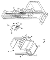
- Fig. 4 shows an embodiment in which the degree of freedom represents a horizontal translation transversely to the direction of travel.
- horizontal running rails 36 are provided on the auxiliary carrier 26', on which the load-receiving section 22 is displaceably mounted (can not be seen in the exploded drawing of Fig. 4 ).
- a spring/damper combination 34 is illustrated, which acts in a similar manner to that of Fig. 2 .
- Semi-active elements or controlled or regulated actuators can also be used for the damping of vibrations in this purely translatory degree of freedom in the same manner as described above.
- the auxiliary carrier 26" comprises a pivot bearing 38, on which the load-receiving section 22 is rotatably mounted (can not be seen in the exploded drawing of Fig. 5 ).
- This degree of rotation freedom is also located in a plane perpendicular to the main direction of travel of the industrial truck 10 and has a horizontal component. Therefore, this additional degree of freedom is also suitable for receiving transverse vibrations and to absorb them by suitable damping.
- a spring/damper element 34 is also shown in the embodiment of Fig. 5 .
- Fig. 5 An advantage of the rotational degree of freedom of Fig. 5 is that this degree of freedom allows for the load-receiving section 22 to be held horizontal even when the industrial truck 10 travels over sloping ground, as is schematically illustrated in Fig. 6 .
- the actuators would be used not only in order to damp the vibrations between the lifting frame 12 and the load-receiving section 22, but also to produce a desired absolute position of the load-receiving section 22, namely a horizontal position. Deviations from this horizontal position can be detected by the position sensors 32 and can be introduced for example into a regulating device, the set value of which corresponding to a horizontal position.
- a so-called skyhook guidance can e.g. be provided, in which the load-receiving section 22 - independently of the ground and the movement of the lifting frame - carries out a pure translation movement, as if it were guided on an imaginary rail.
- a locking mechanism (not shown) is provided, which locks the additional degree of freedom if required.
- This locking mechanism is used for example in load transfer, in which the industrial truck is standing and as rigid a connection as possible between the lifting frame 12 and the load-receiving section 22 is desirable.
Landscapes
- Engineering & Computer Science (AREA)
- Transportation (AREA)
- Structural Engineering (AREA)
- Civil Engineering (AREA)
- Life Sciences & Earth Sciences (AREA)
- Geology (AREA)
- Mechanical Engineering (AREA)
- Forklifts And Lifting Vehicles (AREA)
- Vibration Prevention Devices (AREA)
Abstract
Description
- The present invention relates to an industrial truck with a lifting frame, on which a load-receiving section is mounted so as to be movable vertically, and a method for damping or preventing vibrations in such industrial trucks.
- In the prior art, industrial trucks are used for the placing into storage and removal from storage of loads in high rack warehouses. Examples of such industrial trucks are stacking vehicles such as forklift trucks and forklift reach trucks. A generic industrial truck comprises a lifting frame on which a load-receiving section is mounted so as to be movable vertically. The term "load-receiving section" is to be understood broadly in the present document and can comprise all components which are arranged so as to be movable vertically on the lifting frame. A load fork and a load fork carrier typically belong to the load-receiving section. In some generic industrial trucks, the load-receiving section further comprises a driver's station which is moved vertically on the lifting frame together with the load. Such industrial trucks are known under the term "man-up equipment" or vertical order picker.
- An example for a lifting truck is disclosed in the patent document
WO 2006/137761 A1 which relates to a system for controlling the tilting of a load-carrying implement of a moveable work machine. The implement of the work machine can be tilted about a first axis by a first tilting means and about a second axis by a second means for side tilting. Furthermore, the work machine comprises a control unit for controlling the operation of the first tilting means and the second tilting means. By controlling the tilting of the implement about the axes it is ensured that goods could safely be held by the implement during operation. - A further example for an industrial truck with an improved active positioning system is provided by the
patent document DE 30 17 147 A1 . The load-receiving apparatus comprises a load-receiving fork which can be moved in three directions by means of linear guides which are associated with corresponding driving means. Together with the load-receiving fork the linear guides are disposed at an axle which is pivotally mounted to a bracket by a bearing and which can be driven by driving means in order to perform a fine positioning of the load-receiving fork. - It is a known problem that in generic industrial trucks, vibrations occur in the lifting frame. These vibrations are generally all the more pronounced, the further the load-receiving section is moved vertically, and the amplitude of the vibrations is greatest at the free end of the frame, i.e. in the region of the load-receiving section which has been moved upwards. As long as the load-receiving section oscillates to and fro due to the vibrations of the lifting frame, no loads can be received or deposited. Instead, the operator must wait with the stationary vehicle, until these vibrations have died down. Through these waiting times, however, the productivity of the vehicle is severely reduced. In man-up equipment, as a further problem it occurs that the oscillation movements of the driver's station, which has been moved upwards, are very unpleasant for the operator.
- In the
patent document GB 1 185 997 A - In
DE 32 10 951 C2 the problems of lifting frame vibrations in the receiving and depositing of loads or respectively of load carriers, e.g. pallets, are described. According to the teaching ofDE 32 10 951 - According to
DE 32 10 951 , however, with the aid of the reflex mark and the sensor in addition the phase and amplitude of the vibrations of the lifting frame can be measured in the direction of travel of the industrial truck. The load fork of the described industrial truck is adjustable relative to the lifting frame horizontally in the direction of travel and is provided with a corresponding drive means, in order to move the load fork forward and backward - in relation to the direction of travel of the industrial truck - on depositing or receiving loads. For the damping of the vibrations of the lifting frame in the plane of the direction of travel,DE 32 10 951 - The described active vibration damping only takes place, however, on the receiving or respectively depositing of the load, because the entire controlling or respectively adjusting is oriented to the reflex mark on the shelf or on the pallet. The main purpose of
DE 32 10 951 - A method which is similar in conceptual design for the damping of vibrations of the lifting frame of an industrial truck is known from
applications DE 10 2007 015 488 ,DE 10 2007 024 817 A1EP 1 975 114 A1 - The prior art from the said patent family is similar to the above-mentioned
DE 32 10 951 C2DE 32 10 951 C2 - Despite the steps for the damping of vibrations from the prior art described above, the problem of vibrations in industrial trucks can not be regarded as being solved. Especially with the higher travelling and working speeds which are aimed for in the course of increasing productivity, the vibrations on the lifting frame in practice often constitute a limiting factor.
- The invention is therefore based on the problem of providing an industrial truck and a method in which vibrations in the lifting frame can be efficiently damped or even prevented entirely.
- This problem is solved by an industrial truck according to
Claim 1 and a method according toClaim 14. Advantageous further developments are indicated in the dependent claims. - In the industrial truck according to the invention, the load-receiving section has at least one degree of movement freedom in relation to the lifting frame, which lies in a plane perpendicular to the main direction of travel and has at least one horizontal component. In addition, means are provided for damping or preventing vibrations in the relative position of the load-receiving section and lifting frame along this degree of freedom.
- According to the invention, therefore an additional degree of movement freedom is created between the load-receiving section and the lifting frame. This degree of movement freedom is an additional degree of freedom which is not provided for the intended operation of the industrial truck and serves for a decoupling of the load-receiving section and lifting frame. Instead of the load-receiving section and the lifting frame carrying out a common vibration movement as in the prior art, which would lead to considerable vibration amplitudes in the region of the load-receiving section, this additional degree of freedom allows for the load-receiving section and the lifting frame to vibrate against each other. These vibrations in the relative position of the load-receiving section and lifting frame, which could not occur at all without this additional degree of freedom, are then dissipated by said means for damping or preventing vibrations. In other words, the vibrational energy of the total system of lifting frame and load-receiving section, which is unavoidably produced during operation, is transferred into the newly created degree of freedom and can be dissipated in this degree of freedom by the damping means, so that the vibration energy can be efficiently removed from the total system.
- The additional degree of freedom is perpendicular to the main direction of travel of the vehicle and has at least one horizontal component, whereby vibrations can be efficiently damped transversely to the direction of travel. In practice, vibrations transversely to the direction of travel constitute a particular problem. Transverse vibrations can be produced for example when the industrial truck travels over an unevenness in the ground. As the typical sources of vibrations in the direction of travel, namely braking and accelerating operations, are carried out in a planned manner, these manoeuvres can already be carried out so that only few vibrations occur at all in the direction of travel. This predictability does not exist in the main source of transverse vibrations, namely unevennesses in the ground. Therefore, transverse vibrations can occur in a surprising manner at any time and also can scarcely be avoided by careful operation.
- Transverse vibrations therefore constitute a particular problem, because they harbour the risk that the lifting frame strikes laterally against the shelves. In order to save storage space, small aisle widths are selected between the shelves, which exceed the vehicle width only by a safety distance of 100 mm on both sides. With such small distances between the shelves and the vehicle, collisions with the lifting frame can easily occur through transverse vibrations.
- Compared with the prior art which was discussed in the introduction, the invention therefore has the following conceptual differences:
- (i) An additional degree of freedom is created, which serves for the decoupling of the lifting frame and load-receiving section. In the prior art discussed above, always a drive which was present anyhow and was necessary for the operation was controlled or regulated additionally for the improved damping.
- (ii) Vibrations in the newly created degree of freedom, i.e. the relative movements between load-receiving section and lifting frame, which only become possible through the newly created degree of freedom, are damped. This is different conceptually from the quoted prior art. For example, in
DE 32 10 951DE 10 2007 015 488 - (iii) Finally, contrary to the quoted prior art, the invention allows energy to be dissipated from transverse vibration modes.
- Said motion degree of freedom can be a horizontal translatory degree of freedom, a rotational degree of freedom, swing degree of freedom or a combination of two of these or all these. The "swing degree of freedom" designates here a degree of freedom which is produced when the load-receiving section is articulated on the lifting frame via two parallel pendulum rods and therefore corresponds to a displacement along a circular path, without the load-receiving section itself being rotated. More precise explanations concerning the different degrees of freedom are given below with reference to the example embodiments.
- Preferably, the means for damping and preventing vibrations comprise active, semi-active and/or passive means, which are suitable for producing a force or a moment between the lifting frame and the load-receiving section, which has at least one component along said at least one degree of movement freedom.
- Preferably a restoring element, in particular a spring, is provided which counteracts an elongation between the lifting frame and the load-receiving section along the degree of freedom. In addition, a damping element is preferably provided, which damps relative movements of the load-receiving section and the lifting frame.
- Accordingly, in the simplest case, a simple, passive spring/damper combination can be provided between the lifting frame and the load-receiving section. The vibrations which would be produced in the case of a rigid connection of lifting frame and load-receiving section are converted into a damped relative vibration or oscillation between lifting frame and load-receiving section, so that the vibrational energy in this additional degree of freedom is dissipated effectively and quickly by the damping element.
- In an advantageous further development, the restoring force or the restoring moment of the restoring element and/or the damping characteristic of the damping element can be adapted to one or more operating parameters, in particular to one or more of the following operating parameters: speed of travel, lift height, loading status, deformation status of the lifting frame and/or acceleration status of the lifting frame or of the load-receiving section. Whilst the restoring element and the damping element per se are passive elements, because they do not have any drive means, their characteristics can be adapted as a function of the described operating parameters, in order to optimize the damping effect. The parameters of bending or deformation status or acceleration status are dynamic parameters, to which the restoring- and/or damping element can be adapted in real time, in order to effectively damp or entirely prevent vibrations. Passive elements which are able to be adapted to operating states in such a way are designated in the present document as "semi-active" elements. Semi-active elements in the sense of the present disclosure are elements which are able to be controlled electronically, but do not have their own drive means.
- In an advantageous further development, at least one actuator is provided, which is suited to produce a force or moment between the lifting frame and the load-receiving section, which has at least one component along said at least one degree of movement freedom, and a control device and/or regulating device is provided for controlling or regulating the actuator such that vibrations in the relative position of load-receiving section and lifting frame are damped. The actuator can be an electromechanical, a pneumatic or a hydraulic controlling element. By the use of one or more controlled or regulated actuators, the damping effect can be further increased compared with a construction which is based only on passive or semi-active damping and restoring elements. In particular, such an actuator can be provided as a supplement to the passive or semi-active restoring or damping means.
- Preferably, the controlling or regulating device is connected with at least one sensor for detecting the relative position of the lifting frame and load-receiving section. Preferably, the set value of the regulating device corresponds to a predetermined relative position of the lifting frame and load-receiving section. When the relative deviation or elongation along said degree of freedom is regulated to this set value, this means that the relative vibrations are damped out. In other words, this type of regulation is suitable for removing or dissipating vibration energy from the additional degree of freedom.
- If the degree of freedom comprises a rotatory component, the set value or a further set value of the regulating device can correspond to a horizontal position of the load-receiving section. Thereby, it becomes possible to keep the load-receiving section in a horizontal state, even when the industrial truck travels over sloping ground.
- Preferably, the controlling or regulating device is coupled with at least one sensor for detecting the deformation status of the lifting frame, for example a strain gauge or a piezoelectric sensor. Additionally or alternatively, the controlling or regulating device is preferably coupled with at least one acceleration sensor which is arranged on the lifting frame and/or on the load-receiving section. Preferably, the controlling or regulating device is further arranged to calculate the actuating variable for the actuator, taking into consideration one or more of the following operating parameters: speed of travel, lift height, loading status, bending or deformation status of the lifting frame and/or acceleration status of the lifting frame or of the load-receiving section.
- The operating parameters of speed of travel, lift height and loading status change slowly in relation to the time scale of the regulating process. For each of these statuses, optimized regulator models can be developed and kept in readiness and then processed in the regulator according to the operating status.
- In a particularly advantageous embodiment, several position- or acceleration sensors are arranged on the load-receiving section and the controlling or regulating device is adapted to calculate one or several control values as a function of the measured values of the position or acceleration sensors so that the load-receiving section carries out a pure translation movement. The aim of such a regulation is a status in which the load-receiving section is moved independently of the movement of the chassis of the industrial truck and of the lifting frame, as if it travelled along an imaginary ceiling rail. This type of damping is also designated as "skyhook" damping. Such a skyhook damping is only conceivable, however, because according to the invention one or several additional degrees of movement freedom are created between the load-receiving section and the lifting frame.
- Preferably, said at least one degree of freedom is able to be locked, so that a relative movement is prevented between the lifting frame and the load-receiving section in the locked state. Such a locking is advantageous for example in the load transfer processes at the target position, in order to ensure that no relative movement is produced by the receiving or depositing of the load.
- Preferably, a vertically movable auxiliary carrier is provided on the lifting frame, on which the load-receiving section is fastened movably in the direction of said at least one degree of freedom.
- Further advantages and features of the industrial truck according to the invention and the method for damping or preventing vibrations in industrial trucks become apparent from the following description, in which the invention is explained in further detail with the aid of several example embodiments with reference to the attached drawings, in which
- Fig. 1
- shows a perspective illustration of an industrial truck according to a further development of the invention;
- Fig. 2
- shows an exploded illustration of an industrial truck according to a further development of the invention with an degree of oscillation freedom;
- Fig. 3
- shows two schematic illustrations of the auxiliary carrier of
Fig. 2 ; - Fig. 4
- shows an exploded drawing of an industrial truck with a horizontal translatory degree of freedom;
- Fig. 5
- shows an exploded drawing of an industrial truck with a degree of rotation freedom, and
- Fig. 6
- shows a front view of an industrial truck, in which the load-receiving section is held horizontally on travelling over sloping ground.
-
Fig. 1 shows a perspective view of anindustrial truck 10 with a liftingframe 12 which is telescopically extendable, on which a driver'sstation 14, aload fork carrier 16 and aload fork 18 are fastened, which is partially covered in the figures by apallet 20. Such an industrial truck with a liftable driver's station is also designated as "man-up equipment". The driver'sstation 14, theload fork carrier 16 and theload fork 18 in combination are referred to as "load-receiving section" 22 below. The main direction of travel of theindustrial truck 10 is marked by the arrow 24. -
Fig. 2 shows an exploded illustration of the industrial truck ofFig. 1 according to a first embodiment of the invention. As can be seen inFig. 2 , according to this embodiment anauxiliary carrier 26 is provided which is mounted so as to be movable vertically overguide rollers 28 on the liftingframe 12. - On the
auxiliary carrier 26, tworods 30 are articulated on pivot points A. Although this is not shown in the exploded illustration, therods 30 are articulated with their respectively opposed ends on pivot points B on the driver'sstation 14, i.e. on the load-receivingsection 22. Thereby, an additional degree of movement freedom is created in a plane transverse to the direction of travel, this being, in this example embodiment, a "swing degree of freedom". By the described suspension on theauxiliary carrier 26, the load-receivingsection 22 can carry out a pendulum-like movement transverse to the direction of travel, in which the load-receivingsection 22 is, however, always guided parallel to the liftingframe 12, which as a result corresponds to a displacement along a circular path. Aposition sensor 32 is provided on theauxiliary carrier 26 and on the load-receivingsection 22, more precisely on the driver'sstation 14. The relative displacement or elongation between the auxiliary carrier 26 (or lifting frame 12) and the load-receivingsection 22 then results from the comparison of the measured absolute position information. - In addition, a spring/
damper combination 34 is fastened by a first end C on theauxiliary carrier 26 and by a second end at a point D on the load-receivingsection 22, which can not be seen, however, in the exploded illustration ofFig. 2 . - In Fig. 3a a schematic illustration of the
auxiliary carrier 26 ofFig. 2 is shown in the state of rest, and in Fig. 3b in the displaced or elongated state. In the schematic illustration ofFig. 3 , the points A and C, which are fixed on theauxiliary carrier 26, are illustrated in black and the points B and D, which are fixed on the load-receivingsection 22, are illustrated in white. In the schematic illustration, the spring/damper element 34 was illustrated functionally as a combination ofspring element 34a and damper element 34b arranged in parallel. With reference toFig. 3 , the function of theauxiliary carrier 26 and of the additional degree of freedom created by this is described as follows: - During the travel of an
industrial truck 10, vibrations of the liftingframe 12 often build up, which may lead to an oscillating movement of the load-receivingsection 22. These oscillating movements are all the greater, the higher the load-receivingsection 22 has been moved upwards on or by the liftingframe 12. These oscillating movements are felt to be unpleasant by the driver in the driver'sstation 14 and harbour the danger that the load-receivingsection 22 for example collides with storage shelves. This danger exists in particular in the case of vibrations transversely to the direction of travel. These vibrations usually still last for a certain time after the industrial truck has been stopped for example for a load transfer. This means that between the stopping and the dying down of the vibrations, one must wait for the load transfer, so that this time elapses unproductively. - In the
industrial truck 10 according toFig. 2 , the vibrations which in the case of a rigid connection between liftingframe 12 and load-receivingsection 22 would have lead to the described oscillating movement, are - at least with respect to their component in transverse direction - transferred to the additional swing degree of freedom provided by theauxiliary carrier 26. Instead of a swing or pendular movement of the entire unit of liftingframe 12 and load-receivingsection 22, now a relative vibration occurs along the additional degree of freedom between liftingframe 12 and load-receivingsection 22. By the planned damping of the vibration by means of the additional degree of freedom, it is achieved that with the same stimulus, lower (absolute and relative) vibration amplitudes occur, which die down more quickly through the dissipative effect of the damper 34b than is the case in the current state of the art. In this way, intrusive vibrations are reliably damped or are already prevented from occurring. - With the
position sensors 32, the relative deviation or elongation between liftingframe 12 and load-receivingsection 22 can be determined along the pendular or swing degree of freedom. In the case of a purely passive damping device, as is formed by a simple spring/damper element 34, there is, however, no need yet for the absolute position information of the individual sections (auxiliary carrier 26 or load-receiving section 22) nor for the relative position information which can be derived therefrom. In a further development, the purely passive damping mechanism can, however, be supplemented or replaced by semi-active or active elements. - In a simple further development of the spring/
damper combination 34, it is e.g. possible to adapt the restoring force of thespring 34a and/or the damping characteristic of the damping element 34b to one or more operating parameters. Suitable operating parameters for this are the speed of travel of theindustrial truck 10, the lift height and the loading status of the load-receivingsection 22. For each of these operating parameters, the ideal restoring force and damping characteristic can be determined in advance and then set upon operation. - Whereas these parameters do not change during a vibration cycle, it is also possible to modulate the restoring force and the damping characteristic on a faster time scale shorter than the vibration period. For example, the degree of damping of a damping element can be controlled very rapidly by electrical actuation of a bypass valve, so that it can be adapted optimally and in real time to an acceleration status of the lifting
frame 12 or of the load-receivingsection 22 in order to produce as effective a damping as possible. For this purpose, acceleration sensors can be provided (not shown) on the liftingframe 12 and/or on the load-receivingsection 22. - In addition, it is possible to adapt the degree of damping of the damping element 34b as a function of the bending or deformation status of the lifting
frame 12, which can be determined for example by means of strain gauges or piezoelectric sensors. The state of strain of the lifting frame is valuable information, because the movement resulting from the bending can already be forecast therefrom. It is therefore possible to actuate the damping element 34b as a function of these operating parameters or current system statuses in a manner which results in a more efficient damping of the vibration than is possible with purely passive elements. Such actuatable elements which do not have any drive means themselves are designated herein as semi-active elements. - In addition to or instead of passive or semi-active means for damping or preventing vibrations in the relative position of lifting
frame 12 and load-receivingsection 22, at least one actuator (not shown) can also be provided, which is suitable for generating a force between the liftingframe 12 and the load-receivingsection 22 having at least one component along the swing degree of freedom ofFig. 2 , and which is connected with a controlling device or a regulating device (not shown), in order to control or regulate the actuator such that the vibrations in the relative position of load-receivingsection 22 and liftingframe 12 are damped or prevented. Herein, the relative position between theauxiliary carrier 26 and the load-receivingsection 22 can be determined by means of theposition sensors 32, and the deviation from a set value, which in this case corresponds to the non-deplaced status of Fig. 3a, can be introduced into the regulator. In order to make the regulation algorithm more efficient, in addition to the deviation or displacement from the position of rest, further values can be taken into consideration, in particular the operating parameters already mentioned above, i.e. speed of travel, lift height and loading status, or bending- or deformation status of the liftingframe 12 and acceleration status of the liftingframe 12 or of the load-receivingsection 22. By the use of active control members and a suitable controlling or regulating device, the vibrations can therefore be damped particularly effectively in the additional swing degree of freedom. - The additional swing degree of freedom of
Fig. 2 merely constitutes an example; a number of different degrees of freedom transverse to the direction of travel are likewise conceivable. - By way of example,
Fig. 4 shows an embodiment in which the degree of freedom represents a horizontal translation transversely to the direction of travel. For this, horizontal running rails 36 are provided on the auxiliary carrier 26', on which the load-receivingsection 22 is displaceably mounted (can not be seen in the exploded drawing ofFig. 4 ). In the illustration ofFig. 4 again a spring/damper combination 34 is illustrated, which acts in a similar manner to that ofFig. 2 . Semi-active elements or controlled or regulated actuators can also be used for the damping of vibrations in this purely translatory degree of freedom in the same manner as described above. - A further example is illustrated in
Fig. 5 . In the embodiment ofFig. 5 , theauxiliary carrier 26" comprises a pivot bearing 38, on which the load-receivingsection 22 is rotatably mounted (can not be seen in the exploded drawing ofFig. 5 ). This degree of rotation freedom is also located in a plane perpendicular to the main direction of travel of theindustrial truck 10 and has a horizontal component. Therefore, this additional degree of freedom is also suitable for receiving transverse vibrations and to absorb them by suitable damping. For the absorption of the vibrations, a spring/damper element 34 is also shown in the embodiment ofFig. 5 . However, it would be equally possible to provide a torsion spring and a controllable friction bearing. - In a particularly advantageous embodiment, two or all three of the described degrees of freedom could be combined with each other. An advantage of the rotational degree of freedom of
Fig. 5 is that this degree of freedom allows for the load-receivingsection 22 to be held horizontal even when theindustrial truck 10 travels over sloping ground, as is schematically illustrated inFig. 6 . In this case, the actuators would be used not only in order to damp the vibrations between the liftingframe 12 and the load-receivingsection 22, but also to produce a desired absolute position of the load-receivingsection 22, namely a horizontal position. Deviations from this horizontal position can be detected by theposition sensors 32 and can be introduced for example into a regulating device, the set value of which corresponding to a horizontal position. - By a combination of several degrees of freedom and the detecting of the absolute position or of the acceleration status of the load-receiving
section 22 and a suitable actuation of the associated actuators, a so-called skyhook guidance can e.g. be provided, in which the load-receiving section 22 - independently of the ground and the movement of the lifting frame - carries out a pure translation movement, as if it were guided on an imaginary rail. - In all the embodiments which are shown, expediently a locking mechanism (not shown) is provided, which locks the additional degree of freedom if required. This locking mechanism is used for example in load transfer, in which the industrial truck is standing and as rigid a connection as possible between the lifting
frame 12 and the load-receivingsection 22 is desirable. - Although preferred example embodiments are indicated and described in detail in the drawings and in the above description, this is to be regarded as purely by way of example and not restricting the invention. It is pointed out that only the preferred example embodiments are illustrated and described and all alterations and modifications which currently and in the future lie within the scope of protection of the invention are to be protected.
-
- 10
- industrial truck
- 12
- lifting frame
- 14
- driver's station
- 16
- load fork carrier
- 18
- load fork
- 20
- pallet
- 22
- load-receiving section
- 24
- main direction of travel
- 26,26',26"
- auxiliary carrier
- 28
- roller
- 30
- pendulum rod
- 32
- position sensor
- 34
- spring/damper combination
- 34a
- spring
- 34b
- damper
- 36
- guide rail
- 38
- pivot bearing
Claims (14)
- Industrial truck (10) having a lifting frame (12), on which a load-receiving section (22) is arranged so as to be movable vertically, wherein the load-receiving section (22) has at least one motion degree of freedom in relation to the lifting frame (12) for damping or preventing vibrations in the lifting frame in a direction transversely to the main direction of travel, said motion degree of freedom lying in a plane perpendicular to the main direction of travel (24) and has at least one horizontal component, and that means (34b) are provided for damping or preventing vibrations in the relative position of load-receiving section (22) and lifting frame (12), wherein said at least one motion degree of freedom is an additional degree of freedom which is not provided for the intended operation of the industrial truck (10).
- Industrial truck (10) according to claim 1, in which said motion degree of freedom is a horizontal translatory degree of freedom, a rotational degree of freedom, a swing degree of freedom or a combination of two of these or all of these.
- Industrial truck (10) according to one of the preceding claims, in which the means for damping vibrations comprise active, semi-active and/or passive means (34b) suitable for generating a force or a moment between the lifting frame (12) and the load-receiving section (22), having a component along said at least one motion degree of freedom.
- Industrial truck (10) according to one of the preceding claims, in which a restoring element (34a), in particular a spring is provided, which counteracts a displacement of the lifting frame (12) and load-receiving section (22) along the said motion degree of freedom, and/or
in which a damping element (34b) is provided, which damps relative movements between the load-receiving section (22) and the lifting frame (12). - Industrial truck (10) according to Claim, 4 in which the restoring force of the restoring element (34a) and/or the damping characteristic of the damping element (34b) can be adapted to one or more operating parameters, in particular to one or more of the following operating parameters: speed of travel, lift height, loading status, bending or deformation status of the lifting frame (12), and/or acceleration status of the lifting frame (12) or of the load-receiving section (22).
- Industrial truck (10) according to one of the preceding claims, in which at least one actuator is provided, which is suitable for generating a force between the lifting frame (12) and the load-receiving section (22) having at least one component along said at least one motion degree of freedom, and with a control device and/or regulating device for controlling or regulating the actuator such that vibrations are damped in the relative position the load-receiving section (22) and of the lifting frame (12),
wherein the actuator is preferably an electromechanical, a pneumatic or a hydraulic controlling element. - Industrial truck (10) according to Claim6, in which the control or regulating device is connected with at least one sensor for detecting the relative position of lifting frame (12) and load-receiving section (22),
wherein the set value of the regulating device preferably corresponds to a predetermined relative position of lifting frame (12) and load-receiving section (22). - Industrial truck (10) according to Claim 6 or7, in which said motion degree of freedom comprises a rotatory component and the set value of the regulating device corresponds to a horizontal position of the load-receiving section (22).
- Industrial truck (10) according to Claims 6 to8, in which the control or regulating device is connected with at least one sensor for detecting a bending or deformation status of the lifting frame, in particular a strain gauge or a piezoelectric sensor, and/or
in which the control or regulating device is coupled with at least one acceleration sensor arranged on the lifting frame (12) or on the load-receiving section (22). - Industrial truck (10) according to one of Claims 7 to9, in which the control or regulating device is adapted to calculate the actuating variable for the actuator taking into consideration one or more of the following operating parameters: speed of travel, lift height, loading status, bending or deformation status of the lifting frame (12) and/or acceleration status of the lifting frame (12) or of the load-receiving section (22).
- Industrial truck (10) according to one of Claims 6 to10, in which several position- or acceleration sensors are arranged on the load-receiving section (22) and the regulating device is arranged to calculate one or several control values as a function of the measured values of the position- or acceleration sensors so that the load-receiving section (22) carries out a purely translatory movement.
- Industrial truck (10) according to one of the preceding claims, in which said degree of freedom is able to be locked so that a relative movement between the lifting frame (12) and the load-receiving section (22) is prevented, and/or
in which on the lifting frame (12) a vertically movable auxiliary carrier (26, 26', 26") is arranged, on which the load-receiving section (22) is fastened movably in the direction of said degree of freedom. - Industrial truck (10) according to one of the preceding claims, in which the load-receiving section (22) comprises a driver's station (14).
- A method for damping or preventing vibrations in an industrial truck (10) having a lifting frame (12), on which a load-receiving section (22) is arranged so as to be vertically displaceable, in which active or semi-active means for producing a force or a moment between the lifting frame (12) and the load-receiving section (22) are controlled or regulated so that vibrations are damped or prevented in the relative position of load-receiving section (22) and lifting frame (12) along a motion degree of freedom of the load-receiving section (22) in relation to the lifting frame (12), wherein the motion degree of freedom lies in a plane perpendicular to the main direction of travel (24) of the industrial truck (10) and has at least one horizontal component, and wherein said at least one motion degree of freedom is an additional degree of freedom which is not provided for the intended operation of the industrial truck but for damping or preventing vibrations in the lifting frame in a direction transversely to the main direction of travel.
Applications Claiming Priority (1)
| Application Number | Priority Date | Filing Date | Title |
|---|---|---|---|
| DE102010016062A DE102010016062A1 (en) | 2010-03-22 | 2010-03-22 | Damping or avoiding vibrations in industrial trucks |
Publications (2)
| Publication Number | Publication Date |
|---|---|
| EP2368832A1 EP2368832A1 (en) | 2011-09-28 |
| EP2368832B1 true EP2368832B1 (en) | 2013-06-05 |
Family
ID=44169554
Family Applications (1)
| Application Number | Title | Priority Date | Filing Date |
|---|---|---|---|
| EP20110159184 Active EP2368832B1 (en) | 2010-03-22 | 2011-03-22 | Damping or prevention of vibrations in industrial trucks |
Country Status (4)
| Country | Link |
|---|---|
| US (1) | US8944744B2 (en) |
| EP (1) | EP2368832B1 (en) |
| DE (1) | DE102010016062A1 (en) |
| ES (1) | ES2430965T3 (en) |
Cited By (9)
| Publication number | Priority date | Publication date | Assignee | Title |
|---|---|---|---|---|
| DE202015004375U1 (en) | 2015-01-22 | 2016-04-26 | Jungheinrich Ag | Truck |
| DE102016207523A1 (en) | 2016-05-02 | 2017-11-02 | Jungheinrich Aktiengesellschaft | Industrial truck with a device for reducing transverse vibrations |
| DE102016207526A1 (en) | 2016-05-02 | 2017-11-02 | Jungheinrich Aktiengesellschaft | Industrial truck with a device for reducing vibrations |
| EP3243790A2 (en) | 2016-05-12 | 2017-11-15 | Jungheinrich Aktiengesellschaft | Industrial truck comprising a device for reducing vibrations |
| DE102016209893A1 (en) | 2016-06-06 | 2017-12-07 | Jungheinrich Aktiengesellschaft | Industrial truck with a device for reducing vibrations |
| DE102016211603A1 (en) | 2016-06-28 | 2017-12-28 | Jungheinrich Aktiengesellschaft | Support device with a device for reducing vibrations |
| DE102016211390A1 (en) | 2016-06-24 | 2017-12-28 | Jungheinrich Aktiengesellschaft | Industrial truck with means for suppressing or reducing vibrations |
| DE102016213574A1 (en) | 2016-07-25 | 2018-01-25 | Jungheinrich Aktiengesellschaft | Truck with vibration reduction based on the gyro principle |
| DE102016220810A1 (en) | 2016-10-24 | 2018-04-26 | Jungheinrich Aktiengesellschaft | Proactively reducing vibrations in a truck |
Families Citing this family (16)
| Publication number | Priority date | Publication date | Assignee | Title |
|---|---|---|---|---|
| US8616603B2 (en) * | 2010-04-23 | 2013-12-31 | The Raymond Corporation | Operator ride enhancement system |
| US8731785B2 (en) | 2011-03-18 | 2014-05-20 | The Raymond Corporation | Dynamic stability control systems and methods for industrial lift trucks |
| US9403667B2 (en) | 2011-03-18 | 2016-08-02 | The Raymond Corporation | Dynamic vibration control systems and methods for industrial lift trucks |
| US8763990B2 (en) | 2012-03-20 | 2014-07-01 | The Raymond Corporation | Turn stability systems and methods for lift trucks |
| US9302893B2 (en) | 2013-02-07 | 2016-04-05 | The Raymond Corporation | Vibration control systems and methods for industrial lift trucks |
| US9002557B2 (en) | 2013-03-14 | 2015-04-07 | The Raymond Corporation | Systems and methods for maintaining an industrial lift truck within defined bounds |
| GB201304730D0 (en) * | 2013-03-15 | 2013-05-01 | Packline Ltd | Compac ultra interchangeable carriage with latch pin |
| DE102013113428A1 (en) * | 2013-12-04 | 2015-06-11 | Kion Warehouse Systems Gmbh | Truck |
| US9457999B2 (en) * | 2014-09-25 | 2016-10-04 | Magline, Inc. | Collapsible pallet picking adapter |
| US9840350B2 (en) | 2014-11-05 | 2017-12-12 | Crown Equipment Corporation | Pallet truck with integrated half-size pallet support |
| US9644786B2 (en) * | 2015-05-18 | 2017-05-09 | Christine E. Steiner | Pneumatic double actuating cylinder having a rotatably mounted feeding tray |
| US11046564B2 (en) * | 2015-11-09 | 2021-06-29 | Crown Equipment Corporation | Order picker materials handling vehicle with improved downward visibility when driving elevated |
| ITUA20162917A1 (en) * | 2016-04-27 | 2017-10-27 | Ing Ferretti S R L Con Unico Socio | Handling machine and respective method |
| US10457535B2 (en) * | 2016-11-15 | 2019-10-29 | Roura Material Handling, Inc. | Rotary dumpster |
| US10919748B2 (en) * | 2018-04-11 | 2021-02-16 | Greenfield Products, Llc | Apparatus for handling heavy components on containers |
| CN121361751A (en) | 2020-06-05 | 2026-01-20 | 克朗设备公司 | Operator control system for a materials handling vehicle |
Family Cites Families (26)
| Publication number | Priority date | Publication date | Assignee | Title |
|---|---|---|---|---|
| US3225949A (en) * | 1962-08-17 | 1965-12-28 | Clark Equipment Co | Lift truck with load handling assembly mounted on a movable frame supported by the steering wheel of the truck |
| GB1185997A (en) | 1966-04-19 | 1970-04-02 | Adrian Robert Frater | Improvements in or relating to a fork lift |
| AT305143B (en) * | 1969-07-18 | 1973-02-12 | Guenther Lang Ing | Mobile warehouse control device |
| US3574383A (en) * | 1969-08-26 | 1971-04-13 | Adrian Robert Frater | Fork lift |
| US3757899A (en) * | 1971-03-12 | 1973-09-11 | C & M Manuf Co | Double mast side loader lift truck and double actuator balancing |
| DE2451070C3 (en) * | 1974-10-26 | 1980-09-11 | Licentia Patent-Verwaltungs-Gmbh, 6000 Frankfurt | Load handling device on the lifting carriage of a storage and retrieval vehicle |
| US3972434A (en) * | 1974-12-23 | 1976-08-03 | Allis-Chalmers Corporation | Order picker with operator's platform on the front end of the load support |
| US4095714A (en) | 1976-11-08 | 1978-06-20 | Little Giant Products, Inc. | Load tilting attachment for an industrial truck |
| DE3017147C2 (en) | 1980-05-05 | 1986-02-20 | Jungheinrich Unternehmensverwaltung Kg, 2000 Hamburg | Load handling device for stacker and stacker vehicles, for two- and three-sided forklifts and for storage and retrieval vehicles or storage and retrieval units with a lifting device |
| US4509127A (en) * | 1981-03-31 | 1985-04-02 | Kabushiki Kaisha Toyoda Jidoh Shokki Seisakusho | Control device for loading and unloading mechanism |
| US4413708A (en) * | 1982-03-05 | 1983-11-08 | Caterpillar Tractor Co. | Industrial truck with pivotal front frames |
| DE3210951C2 (en) | 1982-03-25 | 1987-01-08 | Jungheinrich Unternehmensverwaltung Kg, 2000 Hamburg | Stacker with lifting frame |
| US4540330A (en) * | 1984-03-16 | 1985-09-10 | The Knickerbocker Company | Load rotating attachment for lift trucks |
| US5143180A (en) * | 1989-02-17 | 1992-09-01 | Harper Clark N | Load lift truck |
| US5022496A (en) | 1989-12-05 | 1991-06-11 | Crown Equipment Corporation | Slowdown during staging of a turret stockpicker |
| JPH0840510A (en) * | 1994-08-01 | 1996-02-13 | Murata Mach Ltd | Elevating base hanging device |
| US5657834A (en) * | 1994-08-30 | 1997-08-19 | Crown Equipment Corporation | Mast staging cushion apparatus |
| US5579859A (en) * | 1995-02-10 | 1996-12-03 | Crown Equipment Corporation | Isolated floor for material handling vehicle |
| US5984050A (en) * | 1997-05-29 | 1999-11-16 | The Raymond Corporation | Carriage suspension for lift truck |
| US6336565B1 (en) * | 1998-12-01 | 2002-01-08 | Joseph J. Merkel | Articulating truss boom |
| EP1061035A2 (en) * | 1999-06-10 | 2000-12-20 | Murata Kikai Kabushiki Kaisha | Stacker crane |
| GB2379434B (en) * | 2001-09-10 | 2004-09-22 | Lansing Linde Ltd | Industrial truck with a lifting frame |
| DE10319610B4 (en) * | 2002-05-11 | 2011-06-16 | Linde Material Handling Gmbh | Truck with a tilting mast, which is mounted with a rotatably mounted and / or pivotally mounted on a vehicle frame axle body |
| CN101208481B (en) | 2005-06-22 | 2011-06-15 | 沃尔沃建造设备控股(瑞典)有限公司 | A system and method for controlling the inclination of a movable working machine carrying tool, and a movable working machine |
| DE102007015488A1 (en) | 2007-03-30 | 2008-10-02 | Still Wagner Gmbh | Vibration compensation on the mast of a truck |
| DE102007024817B4 (en) | 2007-03-30 | 2021-10-07 | Linde Material Handling Gmbh | Industrial truck with a mast and an actuator to compensate for vibrations |
-
2010
- 2010-03-22 DE DE102010016062A patent/DE102010016062A1/en not_active Withdrawn
-
2011
- 2011-03-21 US US13/052,573 patent/US8944744B2/en active Active
- 2011-03-22 ES ES11159184T patent/ES2430965T3/en active Active
- 2011-03-22 EP EP20110159184 patent/EP2368832B1/en active Active
Cited By (22)
| Publication number | Priority date | Publication date | Assignee | Title |
|---|---|---|---|---|
| DE202015004375U1 (en) | 2015-01-22 | 2016-04-26 | Jungheinrich Ag | Truck |
| EP3048079A1 (en) | 2015-01-22 | 2016-07-27 | Jungheinrich Aktiengesellschaft | Industrial truck |
| DE102015201098A1 (en) | 2015-01-22 | 2016-07-28 | Jungheinrich Aktiengesellschaft | Truck |
| US10046812B2 (en) | 2015-01-22 | 2018-08-14 | Jungheinrich Aktiengesellschaft | Industrial truck |
| EP3241800A1 (en) | 2016-05-02 | 2017-11-08 | Jungheinrich Aktiengesellschaft | Industrial truck with a device for reducing vibrations |
| US10266379B2 (en) | 2016-05-02 | 2019-04-23 | Jungheinrich Aktiengesellschaft | Industrial truck comprising a device for reducing transverse vibrations |
| EP3243791A1 (en) | 2016-05-02 | 2017-11-15 | Jungheinrich Aktiengesellschaft | Industrial truck comprising a device for reducing transverse vibrations |
| US11414311B2 (en) | 2016-05-02 | 2022-08-16 | Jungheinrich Aktiengesellschaft | Industrial truck comprising a device for reducing vibrations |
| US10870563B2 (en) | 2016-05-02 | 2020-12-22 | Jungheinrich Aktiengesellschaft | Industrial truck comprising a device for reducing vibrations |
| DE102016207526A1 (en) | 2016-05-02 | 2017-11-02 | Jungheinrich Aktiengesellschaft | Industrial truck with a device for reducing vibrations |
| DE102016207523A1 (en) | 2016-05-02 | 2017-11-02 | Jungheinrich Aktiengesellschaft | Industrial truck with a device for reducing transverse vibrations |
| EP3243790A2 (en) | 2016-05-12 | 2017-11-15 | Jungheinrich Aktiengesellschaft | Industrial truck comprising a device for reducing vibrations |
| DE102016208205A1 (en) | 2016-05-12 | 2017-11-16 | Jungheinrich Aktiengesellschaft | Industrial truck with a device for reducing vibrations |
| EP3243790A3 (en) * | 2016-05-12 | 2017-11-22 | Jungheinrich Aktiengesellschaft | Industrial truck comprising a device for reducing vibrations |
| US10329131B2 (en) | 2016-05-12 | 2019-06-25 | Jungheinrich Aktiengesellschaft | Industrial truck comprising a device for reducing vibrations |
| DE102016209893A1 (en) | 2016-06-06 | 2017-12-07 | Jungheinrich Aktiengesellschaft | Industrial truck with a device for reducing vibrations |
| US10308489B2 (en) | 2016-06-24 | 2019-06-04 | Jungheinrich Aktiengesellschaft | Industrial truck comprising means for suppressing and reducing vibrations |
| DE102016211390A1 (en) | 2016-06-24 | 2017-12-28 | Jungheinrich Aktiengesellschaft | Industrial truck with means for suppressing or reducing vibrations |
| DE102016211603A1 (en) | 2016-06-28 | 2017-12-28 | Jungheinrich Aktiengesellschaft | Support device with a device for reducing vibrations |
| DE102016213574A1 (en) | 2016-07-25 | 2018-01-25 | Jungheinrich Aktiengesellschaft | Truck with vibration reduction based on the gyro principle |
| DE102016213574B4 (en) | 2016-07-25 | 2022-03-10 | Jungheinrich Aktiengesellschaft | Industrial truck with vibration reduction based on the gyro principle |
| DE102016220810A1 (en) | 2016-10-24 | 2018-04-26 | Jungheinrich Aktiengesellschaft | Proactively reducing vibrations in a truck |
Also Published As
| Publication number | Publication date |
|---|---|
| US20110243699A1 (en) | 2011-10-06 |
| ES2430965T3 (en) | 2013-11-22 |
| DE102010016062A1 (en) | 2011-09-22 |
| EP2368832A1 (en) | 2011-09-28 |
| US8944744B2 (en) | 2015-02-03 |
Similar Documents
| Publication | Publication Date | Title |
|---|---|---|
| EP2368832B1 (en) | Damping or prevention of vibrations in industrial trucks | |
| US11414311B2 (en) | Industrial truck comprising a device for reducing vibrations | |
| JP5517481B2 (en) | Method for vibration damping in premises transport vehicles | |
| US10308489B2 (en) | Industrial truck comprising means for suppressing and reducing vibrations | |
| US10266379B2 (en) | Industrial truck comprising a device for reducing transverse vibrations | |
| US10464793B2 (en) | Industrial truck comprising a device for reducing vibrations | |
| US10046812B2 (en) | Industrial truck | |
| US10329131B2 (en) | Industrial truck comprising a device for reducing vibrations | |
| EP2354078B1 (en) | Industrial truck | |
| US9302893B2 (en) | Vibration control systems and methods for industrial lift trucks | |
| US10800641B2 (en) | Outrigger comprising an apparatus for reducing vibrations | |
| US10071894B2 (en) | Oscillation damping for a material handling vehicle | |
| KR20010007319A (en) | Stacker crane | |
| US20170240397A1 (en) | A Load Handling Apparatus For A Forklift | |
| CN113896135B (en) | Narrow channel forklift with means for preventing vibration of lifting frame and compensating deformation of lifting frame | |
| JP7379926B2 (en) | stacker crane | |
| US20100252523A1 (en) | Transporting apparatus for transporting loads to storage places, in particular in a high-bay warehouse | |
| GB2448024A (en) | Industrial truck having a lifting mast and an actuating element for compensating for oscillations | |
| Sekiya et al. | Pushing control of mobile robot by adjusting deceleration time according to estimated friction effect | |
| SE542357C2 (en) | Floor conveyor with oscillation redution based on the gyroscope principles | |
| HK1234025B (en) | Oscillation damping for a material handling vehicle | |
| HK1234025A1 (en) | Oscillation damping for a material handling vehicle |
Legal Events
| Date | Code | Title | Description |
|---|---|---|---|
| PUAI | Public reference made under article 153(3) epc to a published international application that has entered the european phase |
Free format text: ORIGINAL CODE: 0009012 |
|
| AK | Designated contracting states |
Kind code of ref document: A1 Designated state(s): AL AT BE BG CH CY CZ DE DK EE ES FI FR GB GR HR HU IE IS IT LI LT LU LV MC MK MT NL NO PL PT RO RS SE SI SK SM TR |
|
| AX | Request for extension of the european patent |
Extension state: BA ME |
|
| 17P | Request for examination filed |
Effective date: 20120308 |
|
| GRAP | Despatch of communication of intention to grant a patent |
Free format text: ORIGINAL CODE: EPIDOSNIGR1 |
|
| GRAS | Grant fee paid |
Free format text: ORIGINAL CODE: EPIDOSNIGR3 |
|
| GRAA | (expected) grant |
Free format text: ORIGINAL CODE: 0009210 |
|
| AK | Designated contracting states |
Kind code of ref document: B1 Designated state(s): AL AT BE BG CH CY CZ DE DK EE ES FI FR GB GR HR HU IE IS IT LI LT LU LV MC MK MT NL NO PL PT RO RS SE SI SK SM TR |
|
| REG | Reference to a national code |
Ref country code: GB Ref legal event code: FG4D |
|
| REG | Reference to a national code |
Ref country code: CH Ref legal event code: EP |
|
| REG | Reference to a national code |
Ref country code: AT Ref legal event code: REF Ref document number: 615580 Country of ref document: AT Kind code of ref document: T Effective date: 20130615 |
|
| REG | Reference to a national code |
Ref country code: IE Ref legal event code: FG4D |
|
| REG | Reference to a national code |
Ref country code: DE Ref legal event code: R096 Ref document number: 602011001882 Country of ref document: DE Effective date: 20130801 |
|
| REG | Reference to a national code |
Ref country code: SE Ref legal event code: TRGR |
|
| REG | Reference to a national code |
Ref country code: AT Ref legal event code: MK05 Ref document number: 615580 Country of ref document: AT Kind code of ref document: T Effective date: 20130605 |
|
| PG25 | Lapsed in a contracting state [announced via postgrant information from national office to epo] |
Ref country code: FI Free format text: LAPSE BECAUSE OF FAILURE TO SUBMIT A TRANSLATION OF THE DESCRIPTION OR TO PAY THE FEE WITHIN THE PRESCRIBED TIME-LIMIT Effective date: 20130605 Ref country code: LT Free format text: LAPSE BECAUSE OF FAILURE TO SUBMIT A TRANSLATION OF THE DESCRIPTION OR TO PAY THE FEE WITHIN THE PRESCRIBED TIME-LIMIT Effective date: 20130605 Ref country code: SI Free format text: LAPSE BECAUSE OF FAILURE TO SUBMIT A TRANSLATION OF THE DESCRIPTION OR TO PAY THE FEE WITHIN THE PRESCRIBED TIME-LIMIT Effective date: 20130605 Ref country code: NO Free format text: LAPSE BECAUSE OF FAILURE TO SUBMIT A TRANSLATION OF THE DESCRIPTION OR TO PAY THE FEE WITHIN THE PRESCRIBED TIME-LIMIT Effective date: 20130905 Ref country code: AT Free format text: LAPSE BECAUSE OF FAILURE TO SUBMIT A TRANSLATION OF THE DESCRIPTION OR TO PAY THE FEE WITHIN THE PRESCRIBED TIME-LIMIT Effective date: 20130605 Ref country code: GR Free format text: LAPSE BECAUSE OF FAILURE TO SUBMIT A TRANSLATION OF THE DESCRIPTION OR TO PAY THE FEE WITHIN THE PRESCRIBED TIME-LIMIT Effective date: 20130906 |
|
| REG | Reference to a national code |
Ref country code: NL Ref legal event code: VDEP Effective date: 20130605 |
|
| REG | Reference to a national code |
Ref country code: ES Ref legal event code: FG2A Ref document number: 2430965 Country of ref document: ES Kind code of ref document: T3 Effective date: 20131122 |
|
| REG | Reference to a national code |
Ref country code: LT Ref legal event code: MG4D |
|
| PG25 | Lapsed in a contracting state [announced via postgrant information from national office to epo] |
Ref country code: HR Free format text: LAPSE BECAUSE OF FAILURE TO SUBMIT A TRANSLATION OF THE DESCRIPTION OR TO PAY THE FEE WITHIN THE PRESCRIBED TIME-LIMIT Effective date: 20130605 Ref country code: BG Free format text: LAPSE BECAUSE OF FAILURE TO SUBMIT A TRANSLATION OF THE DESCRIPTION OR TO PAY THE FEE WITHIN THE PRESCRIBED TIME-LIMIT Effective date: 20130905 Ref country code: RS Free format text: LAPSE BECAUSE OF FAILURE TO SUBMIT A TRANSLATION OF THE DESCRIPTION OR TO PAY THE FEE WITHIN THE PRESCRIBED TIME-LIMIT Effective date: 20130605 |
|
| PG25 | Lapsed in a contracting state [announced via postgrant information from national office to epo] |
Ref country code: LV Free format text: LAPSE BECAUSE OF FAILURE TO SUBMIT A TRANSLATION OF THE DESCRIPTION OR TO PAY THE FEE WITHIN THE PRESCRIBED TIME-LIMIT Effective date: 20130605 |
|
| PG25 | Lapsed in a contracting state [announced via postgrant information from national office to epo] |
Ref country code: EE Free format text: LAPSE BECAUSE OF FAILURE TO SUBMIT A TRANSLATION OF THE DESCRIPTION OR TO PAY THE FEE WITHIN THE PRESCRIBED TIME-LIMIT Effective date: 20130605 Ref country code: BE Free format text: LAPSE BECAUSE OF FAILURE TO SUBMIT A TRANSLATION OF THE DESCRIPTION OR TO PAY THE FEE WITHIN THE PRESCRIBED TIME-LIMIT Effective date: 20130605 Ref country code: CZ Free format text: LAPSE BECAUSE OF FAILURE TO SUBMIT A TRANSLATION OF THE DESCRIPTION OR TO PAY THE FEE WITHIN THE PRESCRIBED TIME-LIMIT Effective date: 20130605 Ref country code: IS Free format text: LAPSE BECAUSE OF FAILURE TO SUBMIT A TRANSLATION OF THE DESCRIPTION OR TO PAY THE FEE WITHIN THE PRESCRIBED TIME-LIMIT Effective date: 20131005 Ref country code: SK Free format text: LAPSE BECAUSE OF FAILURE TO SUBMIT A TRANSLATION OF THE DESCRIPTION OR TO PAY THE FEE WITHIN THE PRESCRIBED TIME-LIMIT Effective date: 20130605 Ref country code: PT Free format text: LAPSE BECAUSE OF FAILURE TO SUBMIT A TRANSLATION OF THE DESCRIPTION OR TO PAY THE FEE WITHIN THE PRESCRIBED TIME-LIMIT Effective date: 20131007 |
|
| PG25 | Lapsed in a contracting state [announced via postgrant information from national office to epo] |
Ref country code: RO Free format text: LAPSE BECAUSE OF FAILURE TO SUBMIT A TRANSLATION OF THE DESCRIPTION OR TO PAY THE FEE WITHIN THE PRESCRIBED TIME-LIMIT Effective date: 20130605 Ref country code: NL Free format text: LAPSE BECAUSE OF FAILURE TO SUBMIT A TRANSLATION OF THE DESCRIPTION OR TO PAY THE FEE WITHIN THE PRESCRIBED TIME-LIMIT Effective date: 20130605 Ref country code: PL Free format text: LAPSE BECAUSE OF FAILURE TO SUBMIT A TRANSLATION OF THE DESCRIPTION OR TO PAY THE FEE WITHIN THE PRESCRIBED TIME-LIMIT Effective date: 20130605 |
|
| PLBE | No opposition filed within time limit |
Free format text: ORIGINAL CODE: 0009261 |
|
| STAA | Information on the status of an ep patent application or granted ep patent |
Free format text: STATUS: NO OPPOSITION FILED WITHIN TIME LIMIT |
|
| PG25 | Lapsed in a contracting state [announced via postgrant information from national office to epo] |
Ref country code: DK Free format text: LAPSE BECAUSE OF FAILURE TO SUBMIT A TRANSLATION OF THE DESCRIPTION OR TO PAY THE FEE WITHIN THE PRESCRIBED TIME-LIMIT Effective date: 20130605 |
|
| 26N | No opposition filed |
Effective date: 20140306 |
|
| REG | Reference to a national code |
Ref country code: DE Ref legal event code: R097 Ref document number: 602011001882 Country of ref document: DE Effective date: 20140306 |
|
| PG25 | Lapsed in a contracting state [announced via postgrant information from national office to epo] |
Ref country code: LU Free format text: LAPSE BECAUSE OF FAILURE TO SUBMIT A TRANSLATION OF THE DESCRIPTION OR TO PAY THE FEE WITHIN THE PRESCRIBED TIME-LIMIT Effective date: 20140322 |
|
| REG | Reference to a national code |
Ref country code: CH Ref legal event code: PL |
|
| REG | Reference to a national code |
Ref country code: IE Ref legal event code: MM4A |
|
| PG25 | Lapsed in a contracting state [announced via postgrant information from national office to epo] |
Ref country code: CH Free format text: LAPSE BECAUSE OF NON-PAYMENT OF DUE FEES Effective date: 20140331 Ref country code: LI Free format text: LAPSE BECAUSE OF NON-PAYMENT OF DUE FEES Effective date: 20140331 Ref country code: IE Free format text: LAPSE BECAUSE OF NON-PAYMENT OF DUE FEES Effective date: 20140322 |
|
| PG25 | Lapsed in a contracting state [announced via postgrant information from national office to epo] |
Ref country code: MT Free format text: LAPSE BECAUSE OF FAILURE TO SUBMIT A TRANSLATION OF THE DESCRIPTION OR TO PAY THE FEE WITHIN THE PRESCRIBED TIME-LIMIT Effective date: 20130605 |
|
| PG25 | Lapsed in a contracting state [announced via postgrant information from national office to epo] |
Ref country code: SM Free format text: LAPSE BECAUSE OF FAILURE TO SUBMIT A TRANSLATION OF THE DESCRIPTION OR TO PAY THE FEE WITHIN THE PRESCRIBED TIME-LIMIT Effective date: 20130605 |
|
| REG | Reference to a national code |
Ref country code: DE Ref legal event code: R082 Ref document number: 602011001882 Country of ref document: DE Representative=s name: WEICKMANN & WEICKMANN PATENTANWAELTE - RECHTSA, DE Ref country code: DE Ref legal event code: R082 Ref document number: 602011001882 Country of ref document: DE Representative=s name: WEICKMANN & WEICKMANN PATENT- UND RECHTSANWAEL, DE Ref country code: DE Ref legal event code: R082 Ref document number: 602011001882 Country of ref document: DE |
|
| PG25 | Lapsed in a contracting state [announced via postgrant information from national office to epo] |
Ref country code: MC Free format text: LAPSE BECAUSE OF FAILURE TO SUBMIT A TRANSLATION OF THE DESCRIPTION OR TO PAY THE FEE WITHIN THE PRESCRIBED TIME-LIMIT Effective date: 20130605 |
|
| REG | Reference to a national code |
Ref country code: DE Ref legal event code: R082 Ref document number: 602011001882 Country of ref document: DE Representative=s name: WEICKMANN & WEICKMANN PATENT- UND RECHTSANWAEL, DE Ref country code: FR Ref legal event code: PLFP Year of fee payment: 6 |
|
| PG25 | Lapsed in a contracting state [announced via postgrant information from national office to epo] |
Ref country code: CY Free format text: LAPSE BECAUSE OF FAILURE TO SUBMIT A TRANSLATION OF THE DESCRIPTION OR TO PAY THE FEE WITHIN THE PRESCRIBED TIME-LIMIT Effective date: 20130605 |
|
| PG25 | Lapsed in a contracting state [announced via postgrant information from national office to epo] |
Ref country code: HU Free format text: LAPSE BECAUSE OF FAILURE TO SUBMIT A TRANSLATION OF THE DESCRIPTION OR TO PAY THE FEE WITHIN THE PRESCRIBED TIME-LIMIT; INVALID AB INITIO Effective date: 20110322 Ref country code: TR Free format text: LAPSE BECAUSE OF FAILURE TO SUBMIT A TRANSLATION OF THE DESCRIPTION OR TO PAY THE FEE WITHIN THE PRESCRIBED TIME-LIMIT Effective date: 20130605 |
|
| REG | Reference to a national code |
Ref country code: FR Ref legal event code: PLFP Year of fee payment: 7 |
|
| REG | Reference to a national code |
Ref country code: FR Ref legal event code: PLFP Year of fee payment: 8 |
|
| PG25 | Lapsed in a contracting state [announced via postgrant information from national office to epo] |
Ref country code: MK Free format text: LAPSE BECAUSE OF FAILURE TO SUBMIT A TRANSLATION OF THE DESCRIPTION OR TO PAY THE FEE WITHIN THE PRESCRIBED TIME-LIMIT Effective date: 20130605 |
|
| PG25 | Lapsed in a contracting state [announced via postgrant information from national office to epo] |
Ref country code: AL Free format text: LAPSE BECAUSE OF FAILURE TO SUBMIT A TRANSLATION OF THE DESCRIPTION OR TO PAY THE FEE WITHIN THE PRESCRIBED TIME-LIMIT Effective date: 20130605 |
|
| P01 | Opt-out of the competence of the unified patent court (upc) registered |
Effective date: 20230628 |
|
| PGFP | Annual fee paid to national office [announced via postgrant information from national office to epo] |
Ref country code: ES Payment date: 20250416 Year of fee payment: 15 |
|
| PGFP | Annual fee paid to national office [announced via postgrant information from national office to epo] |
Ref country code: IT Payment date: 20250331 Year of fee payment: 15 |
|
| PGFP | Annual fee paid to national office [announced via postgrant information from national office to epo] |
Ref country code: SE Payment date: 20260323 Year of fee payment: 16 |
|
| PGFP | Annual fee paid to national office [announced via postgrant information from national office to epo] |
Ref country code: GB Payment date: 20260324 Year of fee payment: 16 |
|
| PGFP | Annual fee paid to national office [announced via postgrant information from national office to epo] |
Ref country code: DE Payment date: 20260320 Year of fee payment: 16 |
|
| PGFP | Annual fee paid to national office [announced via postgrant information from national office to epo] |
Ref country code: FR Payment date: 20260325 Year of fee payment: 16 |