EP2368809B1 - Container - Google Patents
Container Download PDFInfo
- Publication number
- EP2368809B1 EP2368809B1 EP10157381.4A EP10157381A EP2368809B1 EP 2368809 B1 EP2368809 B1 EP 2368809B1 EP 10157381 A EP10157381 A EP 10157381A EP 2368809 B1 EP2368809 B1 EP 2368809B1
- Authority
- EP
- European Patent Office
- Prior art keywords
- lid
- peripheral rim
- top opening
- container
- flanges
- Prior art date
- Legal status (The legal status is an assumption and is not a legal conclusion. Google has not performed a legal analysis and makes no representation as to the accuracy of the status listed.)
- Active
Links
Images




Classifications
-
- B—PERFORMING OPERATIONS; TRANSPORTING
- B65—CONVEYING; PACKING; STORING; HANDLING THIN OR FILAMENTARY MATERIAL
- B65D—CONTAINERS FOR STORAGE OR TRANSPORT OF ARTICLES OR MATERIALS, e.g. BAGS, BARRELS, BOTTLES, BOXES, CANS, CARTONS, CRATES, DRUMS, JARS, TANKS, HOPPERS, FORWARDING CONTAINERS; ACCESSORIES, CLOSURES, OR FITTINGS THEREFOR; PACKAGING ELEMENTS; PACKAGES
- B65D43/00—Lids or covers for rigid or semi-rigid containers
- B65D43/02—Removable lids or covers
- B65D43/0202—Removable lids or covers without integral tamper element
- B65D43/0204—Removable lids or covers without integral tamper element secured by snapping over beads or projections
- B65D43/0212—Removable lids or covers without integral tamper element secured by snapping over beads or projections only on the outside, or a part turned to the outside, of the mouth
-
- B—PERFORMING OPERATIONS; TRANSPORTING
- B65—CONVEYING; PACKING; STORING; HANDLING THIN OR FILAMENTARY MATERIAL
- B65D—CONTAINERS FOR STORAGE OR TRANSPORT OF ARTICLES OR MATERIALS, e.g. BAGS, BARRELS, BOTTLES, BOXES, CANS, CARTONS, CRATES, DRUMS, JARS, TANKS, HOPPERS, FORWARDING CONTAINERS; ACCESSORIES, CLOSURES, OR FITTINGS THEREFOR; PACKAGING ELEMENTS; PACKAGES
- B65D43/00—Lids or covers for rigid or semi-rigid containers
- B65D43/02—Removable lids or covers
- B65D43/0202—Removable lids or covers without integral tamper element
- B65D43/0204—Removable lids or covers without integral tamper element secured by snapping over beads or projections
- B65D43/0208—Removable lids or covers without integral tamper element secured by snapping over beads or projections on both the inside and the outside of the mouth of the container
-
- B—PERFORMING OPERATIONS; TRANSPORTING
- B65—CONVEYING; PACKING; STORING; HANDLING THIN OR FILAMENTARY MATERIAL
- B65D—CONTAINERS FOR STORAGE OR TRANSPORT OF ARTICLES OR MATERIALS, e.g. BAGS, BARRELS, BOTTLES, BOXES, CANS, CARTONS, CRATES, DRUMS, JARS, TANKS, HOPPERS, FORWARDING CONTAINERS; ACCESSORIES, CLOSURES, OR FITTINGS THEREFOR; PACKAGING ELEMENTS; PACKAGES
- B65D43/00—Lids or covers for rigid or semi-rigid containers
- B65D43/02—Removable lids or covers
- B65D43/0202—Removable lids or covers without integral tamper element
- B65D43/0225—Removable lids or covers without integral tamper element secured by rotation
- B65D43/0231—Removable lids or covers without integral tamper element secured by rotation only on the outside, or a part turned to the outside, of the mouth of the container
-
- B—PERFORMING OPERATIONS; TRANSPORTING
- B65—CONVEYING; PACKING; STORING; HANDLING THIN OR FILAMENTARY MATERIAL
- B65D—CONTAINERS FOR STORAGE OR TRANSPORT OF ARTICLES OR MATERIALS, e.g. BAGS, BARRELS, BOTTLES, BOXES, CANS, CARTONS, CRATES, DRUMS, JARS, TANKS, HOPPERS, FORWARDING CONTAINERS; ACCESSORIES, CLOSURES, OR FITTINGS THEREFOR; PACKAGING ELEMENTS; PACKAGES
- B65D2543/00—Lids or covers essentially for box-like containers
- B65D2543/00009—Details of lids or covers for rigid or semi-rigid containers
- B65D2543/00018—Overall construction of the lid
- B65D2543/00064—Shape of the outer periphery
- B65D2543/00074—Shape of the outer periphery curved
- B65D2543/00092—Shape of the outer periphery curved circular
-
- B—PERFORMING OPERATIONS; TRANSPORTING
- B65—CONVEYING; PACKING; STORING; HANDLING THIN OR FILAMENTARY MATERIAL
- B65D—CONTAINERS FOR STORAGE OR TRANSPORT OF ARTICLES OR MATERIALS, e.g. BAGS, BARRELS, BOTTLES, BOXES, CANS, CARTONS, CRATES, DRUMS, JARS, TANKS, HOPPERS, FORWARDING CONTAINERS; ACCESSORIES, CLOSURES, OR FITTINGS THEREFOR; PACKAGING ELEMENTS; PACKAGES
- B65D2543/00—Lids or covers essentially for box-like containers
- B65D2543/00009—Details of lids or covers for rigid or semi-rigid containers
- B65D2543/00018—Overall construction of the lid
- B65D2543/00222—Hollow and made of one piece
-
- B—PERFORMING OPERATIONS; TRANSPORTING
- B65—CONVEYING; PACKING; STORING; HANDLING THIN OR FILAMENTARY MATERIAL
- B65D—CONTAINERS FOR STORAGE OR TRANSPORT OF ARTICLES OR MATERIALS, e.g. BAGS, BARRELS, BOTTLES, BOXES, CANS, CARTONS, CRATES, DRUMS, JARS, TANKS, HOPPERS, FORWARDING CONTAINERS; ACCESSORIES, CLOSURES, OR FITTINGS THEREFOR; PACKAGING ELEMENTS; PACKAGES
- B65D2543/00—Lids or covers essentially for box-like containers
- B65D2543/00009—Details of lids or covers for rigid or semi-rigid containers
- B65D2543/00018—Overall construction of the lid
- B65D2543/00259—Materials used
- B65D2543/00296—Plastic
-
- B—PERFORMING OPERATIONS; TRANSPORTING
- B65—CONVEYING; PACKING; STORING; HANDLING THIN OR FILAMENTARY MATERIAL
- B65D—CONTAINERS FOR STORAGE OR TRANSPORT OF ARTICLES OR MATERIALS, e.g. BAGS, BARRELS, BOTTLES, BOXES, CANS, CARTONS, CRATES, DRUMS, JARS, TANKS, HOPPERS, FORWARDING CONTAINERS; ACCESSORIES, CLOSURES, OR FITTINGS THEREFOR; PACKAGING ELEMENTS; PACKAGES
- B65D2543/00—Lids or covers essentially for box-like containers
- B65D2543/00009—Details of lids or covers for rigid or semi-rigid containers
- B65D2543/00342—Central part of the lid
- B65D2543/00398—Reinforcing ribs in the central part of the closure
- B65D2543/00416—Reinforcing ribs in the central part of the closure circular
-
- B—PERFORMING OPERATIONS; TRANSPORTING
- B65—CONVEYING; PACKING; STORING; HANDLING THIN OR FILAMENTARY MATERIAL
- B65D—CONTAINERS FOR STORAGE OR TRANSPORT OF ARTICLES OR MATERIALS, e.g. BAGS, BARRELS, BOTTLES, BOXES, CANS, CARTONS, CRATES, DRUMS, JARS, TANKS, HOPPERS, FORWARDING CONTAINERS; ACCESSORIES, CLOSURES, OR FITTINGS THEREFOR; PACKAGING ELEMENTS; PACKAGES
- B65D2543/00—Lids or covers essentially for box-like containers
- B65D2543/00009—Details of lids or covers for rigid or semi-rigid containers
- B65D2543/00444—Contact between the container and the lid
- B65D2543/00481—Contact between the container and the lid on the inside or the outside of the container
- B65D2543/0049—Contact between the container and the lid on the inside or the outside of the container on the inside, or a part turned to the inside of the mouth of the container
- B65D2543/00518—Skirt
-
- B—PERFORMING OPERATIONS; TRANSPORTING
- B65—CONVEYING; PACKING; STORING; HANDLING THIN OR FILAMENTARY MATERIAL
- B65D—CONTAINERS FOR STORAGE OR TRANSPORT OF ARTICLES OR MATERIALS, e.g. BAGS, BARRELS, BOTTLES, BOXES, CANS, CARTONS, CRATES, DRUMS, JARS, TANKS, HOPPERS, FORWARDING CONTAINERS; ACCESSORIES, CLOSURES, OR FITTINGS THEREFOR; PACKAGING ELEMENTS; PACKAGES
- B65D2543/00—Lids or covers essentially for box-like containers
- B65D2543/00009—Details of lids or covers for rigid or semi-rigid containers
- B65D2543/00444—Contact between the container and the lid
- B65D2543/00592—Snapping means
- B65D2543/00601—Snapping means on the container
- B65D2543/00611—Profiles
- B65D2543/00657—U-shaped or inverted U
-
- B—PERFORMING OPERATIONS; TRANSPORTING
- B65—CONVEYING; PACKING; STORING; HANDLING THIN OR FILAMENTARY MATERIAL
- B65D—CONTAINERS FOR STORAGE OR TRANSPORT OF ARTICLES OR MATERIALS, e.g. BAGS, BARRELS, BOTTLES, BOXES, CANS, CARTONS, CRATES, DRUMS, JARS, TANKS, HOPPERS, FORWARDING CONTAINERS; ACCESSORIES, CLOSURES, OR FITTINGS THEREFOR; PACKAGING ELEMENTS; PACKAGES
- B65D2543/00—Lids or covers essentially for box-like containers
- B65D2543/00009—Details of lids or covers for rigid or semi-rigid containers
- B65D2543/00444—Contact between the container and the lid
- B65D2543/00592—Snapping means
- B65D2543/00601—Snapping means on the container
- B65D2543/00675—Periphery concerned
- B65D2543/00694—Segments
-
- B—PERFORMING OPERATIONS; TRANSPORTING
- B65—CONVEYING; PACKING; STORING; HANDLING THIN OR FILAMENTARY MATERIAL
- B65D—CONTAINERS FOR STORAGE OR TRANSPORT OF ARTICLES OR MATERIALS, e.g. BAGS, BARRELS, BOTTLES, BOXES, CANS, CARTONS, CRATES, DRUMS, JARS, TANKS, HOPPERS, FORWARDING CONTAINERS; ACCESSORIES, CLOSURES, OR FITTINGS THEREFOR; PACKAGING ELEMENTS; PACKAGES
- B65D2543/00—Lids or covers essentially for box-like containers
- B65D2543/00009—Details of lids or covers for rigid or semi-rigid containers
- B65D2543/00444—Contact between the container and the lid
- B65D2543/00592—Snapping means
- B65D2543/00712—Snapping means on the lid
- B65D2543/00722—Profiles
- B65D2543/0074—Massive bead
-
- B—PERFORMING OPERATIONS; TRANSPORTING
- B65—CONVEYING; PACKING; STORING; HANDLING THIN OR FILAMENTARY MATERIAL
- B65D—CONTAINERS FOR STORAGE OR TRANSPORT OF ARTICLES OR MATERIALS, e.g. BAGS, BARRELS, BOTTLES, BOXES, CANS, CARTONS, CRATES, DRUMS, JARS, TANKS, HOPPERS, FORWARDING CONTAINERS; ACCESSORIES, CLOSURES, OR FITTINGS THEREFOR; PACKAGING ELEMENTS; PACKAGES
- B65D2543/00—Lids or covers essentially for box-like containers
- B65D2543/00009—Details of lids or covers for rigid or semi-rigid containers
- B65D2543/00444—Contact between the container and the lid
- B65D2543/00592—Snapping means
- B65D2543/00712—Snapping means on the lid
- B65D2543/00787—Periphery concerned
- B65D2543/00805—Segments
Definitions
- the present invention relates to a container according to the introductory paragraph of claim 1.
- Containers are known having a lid that is required to be mounted on the container in a certain angular position relative to the container in order to subsequently be fastened to the container by rotation of the lid relative to the container.
- An example of such a container is a so-called CD cake box.
- the equipment in order to provide such containers with a lid in an assembly line, the equipment must be especially adapted to position the lid in the correct angular position relative to the container.
- An example of a CD cake box is provided in US 2008/105681 A1 , which document discloses a container according to the preamble of claim 1.
- the object of the present invention is to provide a container of the type described in the introductory part, whereby the mounting of the lid on the container is facilitated.
- a downwards directed skirt portion of the radially protruding flanges of the peripheral rim of the top opening of the container tapers in its longitudinal direction so that its height is smaller at a first end than at a second end.
- the lid may be mounted on the container in any angular position of the lid relative to the container; thereby eliminating the need for equipment especially adapted to position the lid in a certain angular position.
- the radially protruding flanges of the peripheral rim of the top opening and the radially protruding flanges of the lid form primary snap faces adapted to, in the second angular position of the lid relative to the container, mutually contact each other before snapping over each other, and the primary snap faces of at least one of the lid and the peripheral rim of the top opening form an acute angle with the central axis of the peripheral rim of the top opening, the snapping over of the radially protruding flanges may be facilitated in that the angled snap faces may provide a wedge effect tending to lift the respective radially protruding flanges away from each other.
- the flanges of the peripheral rim of the top opening protrude radially outwards
- the flanges of the lid protrude radially inwards
- the primary snap faces of at least one of the lid and the peripheral rim of the top opening extend in a downwards and radially outwards direction
- the flanges of the lid may be provided on the inside of an outer rim of the lid, whereby said outer rim may also serve as a gripping surface for rotating the lid by hand for re-closure of the container.
- the primary snap faces of at least one of the lid and the peripheral rim of the top opening form an angle with the central axis of the peripheral rim of the top opening of less than 75 degrees, preferably less than 70 degrees and more preferred less than 65 degrees. Thereby, snapping over of the radially protruding flanges may be even further facilitated.
- the radially protruding flanges of the peripheral rim of the top opening and the radially protruding flanges of the lid form secondary snap faces adapted to, in the second angular position of the lid relative to the container, mutually contact each other after snapping over of the flanges, and the secondary snap faces of at least one of the lid and the peripheral rim of the top opening form an acute angle with the central axis of the peripheral rim of the top opening.
- the flanges of the peripheral rim of the top opening protrude radially outwards
- the flanges of the lid protrude radially inwards
- the secondary snap faces of at least one of the lid and the peripheral rim of the top opening extend in an upwards and radially outwards direction.
- the radially protruding flanges of the lid are provided on a peripheral rim of the lid, and the peripheral rim of the lid is adapted to flex elastically in order to assist the radially protruding flanges of the lid in snapping over the radially protruding flanges of the peripheral rim of the top opening.
- the radially protruding flanges of the lid may be even further facilitated.
- the peripheral rim of the top opening is adapted to flex elastically in order to assist the radially protruding flanges of the lid in snapping over the radially protruding flanges of the peripheral rim of the top opening. Thereby, snapping over of the radially protruding flanges may be even further facilitated.
- the radially protruding flanges of the peripheral rim of the top opening and the radially protruding flanges of the lid, respectively are provided with mutually interacting end stops preventing the lid from continued angular rotation in the same direction of rotation, when the lid has been rotated from its first angular position to its second angular position relative to the container. Thereby, it may be secured that the lid is positioned correctly in its second angular position whether it is rotated automatically in an assembly line or it is rotated by hand.
- the detachable lid is provided with a downwards protruding peripheral rim adapted to engage sealingly on the inside of the peripheral rim of the top opening of the container when the lid is mounted on the container.
- a fluid tight seal may be obtained without mounting a sealing foil over the top opening of the container.
- the present invention also provides a method of automatically mounting lids on containers, each container comprising a side wall, a bottom and a top opening with a peripheral rim and being provided with a detachable lid adapted to engage the peripheral rim of the top opening, the peripheral rim of the top opening being provided with a number of mutually spaced, radially protruding flanges, and the lid being provided with a corresponding number of mutually spaced, radially protruding flanges adapted to, in a first angular position of the lid relative to the container, pass in between the radially protruding flanges of the peripheral rim of the top opening and subsequently, after rotation of the lid about a central axis of the peripheral rim of the top opening to a second angular position relative to the container, be engaged with the radially protruding flanges of the peripheral rim of the top opening, so that the lid is locked onto the container, each lid being mounted on a respective container by positioning the lid on
- each lid is positioned on the rim of the top opening of the respective container in any angular position relative to the container, and by that, when the lid is pressed onto the peripheral rim of the top opening, in the case that the lid is not in the first angular position of the lid relative to the container, the radially protruding flanges of the peripheral rim of the top opening and the radially protruding flanges of the lid, respectively, snap over each other, thereby locking the lid onto the container.
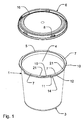
- Fig. 1 shows a container 1 comprising a side wall 2, a bottom 3 and a top opening 4 with a peripheral rim 5.
- the container 1 is provided with a detachable lid 6 adapted to engage the peripheral rim 5 of the top opening 4.
- the peripheral rim 5 of the top opening 4 is provided with a number of mutually spaced, radially outwards protruding flanges 7, and the lid 6 is provided with a corresponding number of mutually spaced, radially inwards protruding flanges 8 adapted to go into engagement with the radially outwards protruding flanges 7 of the peripheral rim of the top opening, so that the lid 6 is locked onto the container 1.
- the lid 6 rests on the peripheral rim 5 of the top opening 4 of the container 1, and the radially inwards protruding flanges 8 of the lid 6 are positioned below the radially outwards protruding flanges 7 of the peripheral rim of the top opening; see for instance Figs. 5 and 6 and Figs. 7 and 8 .
- the lid 6 may be positioned in a first angular position of the lid 6 relative to the container 1, whereby the radially inwards protruding flanges 8 of the lid 6 may pass in between the radially outwards protruding flanges 7 of the peripheral rim 5 of the top opening 4.
- each pair of radially outwards protruding flanges 7 of the peripheral rim 5 are separated by means of a space 10.
- each radially inwards protruding flange 8 of the lid 6 is positioned at a space 10 between two radially outwards protruding flanges 7 of the peripheral rim 5, so that the lid 6 may be displaced slightly in downwards direction until abutment against the peripheral rim 5 of the top opening 4, whereby the radially inwards protruding flanges 8 of the lid 6 passes through respective spaces 10 between radially outwards protruding flanges 7 of the peripheral rim 5.
- the lid 6 may be rotated in clockwise direction about a central axis 9 of the peripheral rim 5 of the top opening 4 to a second angular position relative to the container 1, whereby the radially inwards protruding flanges 8 of the lid 6 are displaced to a position under and in engagement with the radially outwards protruding flanges 7 of the peripheral rim 5 of the top opening 4, so that the lid 6 is locked onto the container 1.
- the radially outwards protruding flanges 7 of the peripheral rim 5 of the top opening 4 are provided with end stops 11 formed as downwards directed protrusions of a downwards directed skirt portion 12 of the radially outwards protruding flanges 7 of the peripheral rim 5.
- the radially inwards protruding flanges 8 of the lid 6 are provided with end stops 13 in the form of end faces adapted to mutually interact with, that is abut, the end stops 11 of the radially outwards protruding flanges 7 in the second angular position of the lid 6 relative to the container 1.
- the lid 6 may continue its angular rotation in the same rotational direction and thereby leave its second angular position, when the lid 6 has once been rotated from its first angular position to its second angular position relative to the container.
- this rotation is performed in clockwise direction; however, in other embodiments of the lid and container, this rotation may be performed in anti-clockwise direction.
- the downwards directed skirt portion 12 of the radially outwards protruding flanges 7 of the peripheral rim 5 may, as it is seen, for instance, in Figs.
- the radially protruding flanges 7 of the peripheral rim 5 may extend obliquely relative to the horizontal.
- the radially protruding flanges 8 of the lid 6 may have a corresponding tapering form or extend obliquely relative to the horizontal.
- the first angular position of the lid 6 relative to the container 1 means any angular position of the lid, in which the radially inwards protruding flanges 8 of the lid 6 may pass in between the radially outwards protruding flanges 7 of the peripheral rim 5 of the top opening 4, as described above.
- the second angular position of the lid 6 relative to the container 1 means any angular position of the lid in which the lid is not in its first angular position, that is, an angular position in which the radially inwards protruding flanges 8 of the lid 6 may not pass in between the radially outwards protruding flanges 7 of the peripheral rim 5 of the top opening 4.
- each downwards directed skirt portion 12 of the radially outwards protruding flanges 7 of the peripheral rim 5 is provided with a rounded indentation 14 into which a correspondingly rounded protrusion 15 of a corresponding radially inwards protruding flange 8 may snap in order to subsequently rest there in a second angular position of the lid 6 relative to the container 1.
- the lid 6 may be prevented from unintentionally rotating away from said second angular position relative to the container and it may thereby be ensured that the lid is suitably locked onto the container.
- the indentations 14 and the protrusions 15 may have any suitable form other than the shown rounded form, for instance they may be V-formed or simply be formed by means of small taps adapted to snap over each other.
- the lid 6 may also be brought into its locked position on the container 1 by means of an alternative mounting procedure.
- this alternative mounting procedure in the second angular position of the lid 6 relative to the container 1, the lid may be pressed onto the peripheral rim of the top opening, whereby the radially outwards protruding flanges 7 of the peripheral rim 5 of the top opening 4 and the radially inwards protruding flanges 8 of the lid 6 snap over each other, thereby locking the lid onto the container.
- Fig. 5 shows a radial cross-section through a detail of the container 1 and the lid 6 before pressing the lid against the container
- FIG. 6 shows a corresponding cross-section of the container 1 and the lid 6 after the mounting of the lid on the container by snapping over of the radially outwards protruding flanges 7 of the peripheral rim 5 of the top opening 4 and the radially inwards protruding flanges 8 of the lid 6.
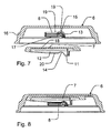
- Figs. 7 and 8 each shows a sectional view taken along a line parallel to a central axis of the container and similarly illustrating the situation before and after the snapping over procedure.
- the radially outwards protruding flanges 7 of the peripheral rim 5 of the top opening 4 and the radially inwards protruding flanges 8 of the lid 6, respectively, are adapted to, by pressing the lid 6 onto the peripheral rim 5 of the top opening 4, in the second angular position of the lid 6 relative to the container 1, snap over each other, thereby locking the lid onto the container.
- This adaptation of the radially outwards protruding flanges 7 of the peripheral rim 5 of the top opening 4 and the radially inwards protruding flanges 8 of the lid 6 may be achieved in any suitable way, for instance by means of the form of the flanges, their flexibility, their surface, their relative position, etc.
- the concept of adaptation of the flanges 7, 8 is also intended to include any suitable adaptation of elements related to and interacting with the flanges 7, 8, such as the rim 5 of the top opening 4 on which the radially outwards protruding flanges 7 of the container 1 are provided, and such as an outer downwards extending peripheral rim 16 of the lid 6 on which the radially inwards protruding flanges 8 are provided, etc.
- the primary snap faces 17 of the lid form an acute angle with the central axis 9 of the peripheral rim 5 of the top opening 4, cf. Figs. 1 and 2 .
- the primary snap faces 18 of the peripheral rim 5 of the top opening 4 may form an acute angle with the central axis 9 of the peripheral rim of the top opening.
- the flanges 7 of the peripheral rim 5 of the top opening 4 protrude radially outwards
- the flanges 8 of the lid 6 protrude radially inwards
- the primary snap faces 17 of the lid 6 extend in a downwards and radially outwards direction
- the primary snap faces 18 of the peripheral rim 5 may similarly extend in a downwards and radially outwards direction.
- the flanges 7 of the peripheral rim 5 of the top opening 4 protrude radially inwards
- the flanges 8 of the lid 6 protrude radially outwards
- the primary snap faces 17 of the lid 6 and/or the primary snap faces 18 of the peripheral rim 5 extend in an upwards and radially outwards direction.
- the latter embodiment could, for instance, be realized by turning the container and lid shown in the figures upside down, whereby a container similar to a so-called CD cake box could be obtained.
- the primary snap faces 17, 18 of at least one of the lid 6 and the peripheral rim 5 of the top opening 4 may form an angle with the central axis 9 of the peripheral rim of the top opening of less than 75 degrees, preferably less than 70 degrees and more preferred less than 65 degrees.
- the secondary snap faces 19, 20 of both the lid 6 and the peripheral rim 5 of the top opening 4 form an acute angle with the central axis 9 of the peripheral rim 5 of the top opening 4.
- the flanges 7 of the peripheral rim 5 of the top opening 4 protrude radially outwards
- the flanges 8 of the lid 6 protrude radially inwards
- the secondary snap faces 19, 20 of the lid and the peripheral rim of the top opening extend in an upwards and radially outwards direction.
- the flanges 7 of the peripheral rim 5 of the top opening 4 protrude radially inwards
- the flanges 8 of the lid 6 protrude radially outwards
- the secondary snap faces 19 of the lid and/or the secondary snap faces 20 of the peripheral rim 5 of the top opening 4 extend in a downwards and radially outwards direction.
- the radially inwards protruding flanges 8 of the lid 6 are provided on the outer downwards extending peripheral rim 16 of the lid, and the outer downwards extending peripheral rim 16 of the lid may be adapted to flex elastically in order to assist the radially inwards protruding flanges 8 of the lid in snapping over the radially outwards protruding flanges 7 of the peripheral rim 5 of the top opening 4.
- the peripheral rim 5 of the top 4 opening may be adapted to flex elastically in order to assist the flanges 7, 8 in snapping over each other.
- the radially inwards protruding flanges 8 of the lid 6 have a longitudinal extension that is smaller than the longitudinal extension of the radially outwards protruding flanges 7 of the peripheral rim of the top opening.
- this relative relationship may just as well be the other way around, or the flanges 7, 8 may be of substantially even longitudinal extension.
- the radially outwards protruding flanges 7 of the peripheral rim 5 at a first end, have a tapering portion 21 reducing its radius to the outer radius of the rim 5 in the spaces 10 separating each pair of flanges 7.
- Each combination of a radially outwards protruding flange 7 and the outside of the rim 5 in a space 10 may also in continuation of each other form one element having a continuously tapering width making the difference between the flanges 7 and the outside of the rim 5 in the spaces 10 invisible; however, this difference, that is, where this element changes from being the flange 7 to being the outside of the rim 5 in the space 10, will depend on whether the radially inwards protruding flanges 8 of the lid 6 may pass substantially freely in between the radially outwards protruding flanges 7 or not; if they may pass substantially freely, they are located at the spaces 10.
- Figs. 13 to 16 shows another embodiment of the container 1 and lid 6 according to the invention, wherein the detachable lid 6 is provided with a downwards protruding peripheral rim 22 adapted to engage sealingly on the inside of the peripheral rim 5 of the top opening 4 of the container 1 when the lid is mounted on the container.
- a fluid tight seal may be obtained as it is well illustrated in Fig. 15 .
- the downwards protruding peripheral rim 22 may be slightly conical on its outside so that it tapers in downward direction; thereby obtaining a tight seal by tightening the lid 6 on the container 1 may be further facilitated.
- the expression inwards, when relating to the radially protruding flanges 8 of the lid 6 or the radially protruding flanges 7 of the peripheral rim 5 of the top opening 4 or when relating to anything else along the periphery of the container 1 means directed against a central vertical axis through the container when the container 1 is placed with its bottom 3 on a horizontal surface and when the lid 6 is engaged with the peripheral rim of the top opening.
- Outwards relates to the opposite direction, which is away from said central vertical axis.
- all directions mentioned in this application relate to the container 1 when it is placed with its bottom on a horizontal surface.
Landscapes
- Engineering & Computer Science (AREA)
- Mechanical Engineering (AREA)
- Closures For Containers (AREA)
- Glass Compositions (AREA)
Description
- The present invention relates to a container according to the introductory paragraph of
claim 1. - Containers are known having a lid that is required to be mounted on the container in a certain angular position relative to the container in order to subsequently be fastened to the container by rotation of the lid relative to the container. An example of such a container is a so-called CD cake box. However, in order to provide such containers with a lid in an assembly line, the equipment must be especially adapted to position the lid in the correct angular position relative to the container. An example of a CD cake box is provided in
US 2008/105681 A1 , which document discloses a container according to the preamble ofclaim 1. - The object of the present invention is to provide a container of the type described in the introductory part, whereby the mounting of the lid on the container is facilitated.
- In view of this object, a downwards directed skirt portion of the radially protruding flanges of the peripheral rim of the top opening of the container tapers in its longitudinal direction so that its height is smaller at a first end than at a second end. Thereby, when the lid is rotated in order to engage the radially protruding flanges of the lid under the radially protruding flanges of the peripheral rim of the top opening, the lid may be tightened against the peripheral rim of the top opening, and thereby a sealing effect may be ensured.
- Another advantage of the container as claimed in
claim 1 is that the lid may be mounted on the container in any angular position of the lid relative to the container; thereby eliminating the need for equipment especially adapted to position the lid in a certain angular position. - Since the radially protruding flanges of the peripheral rim of the top opening and the radially protruding flanges of the lid, respectively, form primary snap faces adapted to, in the second angular position of the lid relative to the container, mutually contact each other before snapping over each other, and the primary snap faces of at least one of the lid and the peripheral rim of the top opening form an acute angle with the central axis of the peripheral rim of the top opening, the snapping over of the radially protruding flanges may be facilitated in that the angled snap faces may provide a wedge effect tending to lift the respective radially protruding flanges away from each other.
- Furthermore since the flanges of the peripheral rim of the top opening protrude radially outwards, the flanges of the lid protrude radially inwards, and the primary snap faces of at least one of the lid and the peripheral rim of the top opening extend in a downwards and radially outwards direction, the flanges of the lid may be provided on the inside of an outer rim of the lid, whereby said outer rim may also serve as a gripping surface for rotating the lid by hand for re-closure of the container.
- In an embodiment, the primary snap faces of at least one of the lid and the peripheral rim of the top opening form an angle with the central axis of the peripheral rim of the top opening of less than 75 degrees, preferably less than 70 degrees and more preferred less than 65 degrees. Thereby, snapping over of the radially protruding flanges may be even further facilitated.
- In an embodiment, the radially protruding flanges of the peripheral rim of the top opening and the radially protruding flanges of the lid, respectively, form secondary snap faces adapted to, in the second angular position of the lid relative to the container, mutually contact each other after snapping over of the flanges, and the secondary snap faces of at least one of the lid and the peripheral rim of the top opening form an acute angle with the central axis of the peripheral rim of the top opening. Thereby, snapping over of the radially protruding flanges may be even further facilitated in that is may be better ensured that the radially protruding flanges snap correctly into locking engagement.
- In an embodiment, the flanges of the peripheral rim of the top opening protrude radially outwards, the flanges of the lid protrude radially inwards, and the secondary snap faces of at least one of the lid and the peripheral rim of the top opening extend in an upwards and radially outwards direction. Thereby, a wedge effect may be accomplished whereby the lid is tightened appropriately onto the peripheral rim of the container when the secondary snap faces snap into contact with each other.
- In an embodiment, the radially protruding flanges of the lid are provided on a peripheral rim of the lid, and the peripheral rim of the lid is adapted to flex elastically in order to assist the radially protruding flanges of the lid in snapping over the radially protruding flanges of the peripheral rim of the top opening. Thereby, snapping over of the radially protruding flanges may be even further facilitated.
- In an embodiment, the peripheral rim of the top opening is adapted to flex elastically in order to assist the radially protruding flanges of the lid in snapping over the radially protruding flanges of the peripheral rim of the top opening. Thereby, snapping over of the radially protruding flanges may be even further facilitated.
- In an embodiment, the radially protruding flanges of the peripheral rim of the top opening and the radially protruding flanges of the lid, respectively, are provided with mutually interacting end stops preventing the lid from continued angular rotation in the same direction of rotation, when the lid has been rotated from its first angular position to its second angular position relative to the container. Thereby, it may be secured that the lid is positioned correctly in its second angular position whether it is rotated automatically in an assembly line or it is rotated by hand.
- In an embodiment, the detachable lid is provided with a downwards protruding peripheral rim adapted to engage sealingly on the inside of the peripheral rim of the top opening of the container when the lid is mounted on the container. Thereby, a fluid tight seal may be obtained without mounting a sealing foil over the top opening of the container.
- The present invention also provides a method of automatically mounting lids on containers, each container comprising a side wall, a bottom and a top opening with a peripheral rim and being provided with a detachable lid adapted to engage the peripheral rim of the top opening, the peripheral rim of the top opening being provided with a number of mutually spaced, radially protruding flanges, and the lid being provided with a corresponding number of mutually spaced, radially protruding flanges adapted to, in a first angular position of the lid relative to the container, pass in between the radially protruding flanges of the peripheral rim of the top opening and subsequently, after rotation of the lid about a central axis of the peripheral rim of the top opening to a second angular position relative to the container, be engaged with the radially protruding flanges of the peripheral rim of the top opening, so that the lid is locked onto the container, each lid being mounted on a respective container by positioning the lid on the rim of the top opening, pressing the lid onto the peripheral rim of the top opening and providing the lid with a rotational force relative to the container.
- The method is characterized by that each lid is positioned on the rim of the top opening of the respective container in any angular position relative to the container, and by that, when the lid is pressed onto the peripheral rim of the top opening, in the case that the lid is not in the first angular position of the lid relative to the container, the radially protruding flanges of the peripheral rim of the top opening and the radially protruding flanges of the lid, respectively, snap over each other, thereby locking the lid onto the container. Thereby, the above-mentioned properties may be obtained.
- The invention will now be explained in more detail below by means of examples of embodiments with reference to the very schematic drawing, in which
-
Fig. 1 is a perspective view of a container according to the invention, whereby the lid has been detached from the container; -
Fig. 2 is an axial section through the container shown inFig. 1 , whereby the lid has been attached on the container; -
Fig. 3 is side view of the container shown inFig. 1 , whereby the lid has been attached on the container; -
Fig. 4 is a top view of the container shown inFig. 3 ; -
Fig. 5 is a cross-sectional detail on a larger scale of the container as indicated inFig. 2 , whereby the lid has been detached from the container; -
Fig. 6 is the cross-sectional detail ofFig. 5 , whereby the lid has been attached on the container; -
Fig. 7 is a cross-sectional detail on a larger scale of the container as indicated inFig. 3 , whereby the lid has been detached from the container; -
Fig. 8 is the cross-sectional detail ofFig. 7 , whereby the lid has been attached on the container; -
Fig. 9 is a cross-sectional view shown in perspective of the container shown inFig. 1 , whereby the lid has detached from the container; -
Fig. 10 is the cross-sectional view ofFig. 9 , whereby the lid has been attached on the container; -
Fig. 11 is a cross-sectional detail on a larger scale of the container as indicated inFig. 9 ; -
Fig. 12 is a cross-sectional detail on a larger scale of the container as indicated inFig. 10 ; -
Fig. 13 is an axial section through another embodiment of the container shown inFig. 2 ; -
Fig. 14 is a perspective view of the lid of the embodiment of the container shown inFig. 13 ; -
Fig. 15 is a cross-sectional detail on a larger scale of the container as indicated inFig. 13 ; and -
Fig. 16 is a cross-sectional view shown in perspective of the container shown inFig. 13 . -
Fig. 1 shows acontainer 1 comprising aside wall 2, abottom 3 and a top opening 4 with aperipheral rim 5. Thecontainer 1 is provided with adetachable lid 6 adapted to engage theperipheral rim 5 of the top opening 4. Theperipheral rim 5 of the top opening 4 is provided with a number of mutually spaced, radially outwards protrudingflanges 7, and thelid 6 is provided with a corresponding number of mutually spaced, radially inwards protrudingflanges 8 adapted to go into engagement with the radially outwards protrudingflanges 7 of the peripheral rim of the top opening, so that thelid 6 is locked onto thecontainer 1. In this locked position, thelid 6 rests on theperipheral rim 5 of the top opening 4 of thecontainer 1, and the radially inwards protrudingflanges 8 of thelid 6 are positioned below the radially outwards protrudingflanges 7 of the peripheral rim of the top opening; see for instanceFigs. 5 and 6 andFigs. 7 and 8 . - In order to mount the
lid 6 on thecontainer 1, firstly, thelid 6 may be positioned in a first angular position of thelid 6 relative to thecontainer 1, whereby the radially inwards protrudingflanges 8 of thelid 6 may pass in between the radially outwards protrudingflanges 7 of theperipheral rim 5 of the top opening 4. As it may be seen inFig. 1 , each pair of radially outwards protrudingflanges 7 of theperipheral rim 5 are separated by means of aspace 10. Therefore, in the first angular position of thelid 6 relative to thecontainer 1, each radially inwards protrudingflange 8 of thelid 6 is positioned at aspace 10 between two radially outwards protrudingflanges 7 of theperipheral rim 5, so that thelid 6 may be displaced slightly in downwards direction until abutment against theperipheral rim 5 of the top opening 4, whereby the radially inwards protrudingflanges 8 of thelid 6 passes throughrespective spaces 10 between radially outwards protrudingflanges 7 of theperipheral rim 5. Secondly, thelid 6 may be rotated in clockwise direction about acentral axis 9 of theperipheral rim 5 of the top opening 4 to a second angular position relative to thecontainer 1, whereby the radially inwards protrudingflanges 8 of thelid 6 are displaced to a position under and in engagement with the radially outwards protrudingflanges 7 of theperipheral rim 5 of the top opening 4, so that thelid 6 is locked onto thecontainer 1. - It is noted that, in the embodiments shown in the figures, the radially outwards protruding
flanges 7 of theperipheral rim 5 of the top opening 4 are provided withend stops 11 formed as downwards directed protrusions of a downwards directedskirt portion 12 of the radially outwards protrudingflanges 7 of theperipheral rim 5. Correspondingly, the radially inwards protrudingflanges 8 of thelid 6 are provided withend stops 13 in the form of end faces adapted to mutually interact with, that is abut, the end stops 11 of the radially outwards protrudingflanges 7 in the second angular position of thelid 6 relative to thecontainer 1. Thereby, it may be prevented that thelid 6 may continue its angular rotation in the same rotational direction and thereby leave its second angular position, when thelid 6 has once been rotated from its first angular position to its second angular position relative to the container. As noted above, in the shown embodiments, this rotation is performed in clockwise direction; however, in other embodiments of the lid and container, this rotation may be performed in anti-clockwise direction. The downwards directedskirt portion 12 of the radially outwards protrudingflanges 7 of theperipheral rim 5 may, as it is seen, for instance, inFigs. 1 ,7 and 8 , taper in its longitudinal direction so that its height is smaller at a first end than at a second end, that is, in the embodiment shown, its height is smaller at its end opposed to theend stop 11 than at its end at the end stop. Thereby, when the lid is rotated in order to engage the radially inwards protrudingflanges 8 of thelid 6 under the radially outwards protrudingflanges 7 of the peripheral rim of the top opening, the lid may be appropriately tightened against the peripheral rim of the top opening, and thereby a sealing effect may be ensured. - Instead of providing the radially protruding
flanges 7 of theperipheral rim 5 with a tapering, downwards directedskirt portion 12, the radially protrudingflanges 7 may extend obliquely relative to the horizontal. Alternatively or supplementary, the radially protrudingflanges 8 of thelid 6 may have a corresponding tapering form or extend obliquely relative to the horizontal. Thereby, similarly, a tightening effect may be obtained. - It is noted that in the context of this description, the first angular position of the
lid 6 relative to thecontainer 1 means any angular position of the lid, in which the radially inwards protrudingflanges 8 of thelid 6 may pass in between the radially outwards protrudingflanges 7 of theperipheral rim 5 of the top opening 4, as described above. On the other hand, the second angular position of thelid 6 relative to thecontainer 1 means any angular position of the lid in which the lid is not in its first angular position, that is, an angular position in which the radially inwards protrudingflanges 8 of thelid 6 may not pass in between the radially outwards protrudingflanges 7 of theperipheral rim 5 of the top opening 4. - It is furthermore noted that each downwards directed
skirt portion 12 of the radially outwards protrudingflanges 7 of theperipheral rim 5 is provided with arounded indentation 14 into which a correspondinglyrounded protrusion 15 of a corresponding radially inwards protrudingflange 8 may snap in order to subsequently rest there in a second angular position of thelid 6 relative to thecontainer 1. Thereby, thelid 6 may be prevented from unintentionally rotating away from said second angular position relative to the container and it may thereby be ensured that the lid is suitably locked onto the container. Theindentations 14 and theprotrusions 15 may have any suitable form other than the shown rounded form, for instance they may be V-formed or simply be formed by means of small taps adapted to snap over each other. - Alternatively to the above described mounting procedure for the lid, according to the invention, the
lid 6 may also be brought into its locked position on thecontainer 1 by means of an alternative mounting procedure. According to this alternative mounting procedure, in the second angular position of thelid 6 relative to thecontainer 1, the lid may be pressed onto the peripheral rim of the top opening, whereby the radially outwards protrudingflanges 7 of theperipheral rim 5 of the top opening 4 and the radially inwards protrudingflanges 8 of thelid 6 snap over each other, thereby locking the lid onto the container.Fig. 5 shows a radial cross-section through a detail of thecontainer 1 and thelid 6 before pressing the lid against the container, andFig. 6 shows a corresponding cross-section of thecontainer 1 and thelid 6 after the mounting of the lid on the container by snapping over of the radially outwards protrudingflanges 7 of theperipheral rim 5 of the top opening 4 and the radially inwards protrudingflanges 8 of thelid 6.Figs. 7 and 8 each shows a sectional view taken along a line parallel to a central axis of the container and similarly illustrating the situation before and after the snapping over procedure. - In order to enable this alternative mounting procedure of the
lid 6 on thecontainer 1, the radially outwards protrudingflanges 7 of theperipheral rim 5 of the top opening 4 and the radially inwards protrudingflanges 8 of thelid 6, respectively, are adapted to, by pressing thelid 6 onto theperipheral rim 5 of the top opening 4, in the second angular position of thelid 6 relative to thecontainer 1, snap over each other, thereby locking the lid onto the container. This adaptation of the radially outwards protrudingflanges 7 of theperipheral rim 5 of the top opening 4 and the radially inwards protrudingflanges 8 of thelid 6 may be achieved in any suitable way, for instance by means of the form of the flanges, their flexibility, their surface, their relative position, etc. In this application, the concept of adaptation of theflanges flanges rim 5 of the top opening 4 on which the radially outwards protrudingflanges 7 of thecontainer 1 are provided, and such as an outer downwards extendingperipheral rim 16 of thelid 6 on which the radially inwards protrudingflanges 8 are provided, etc. - Due to this alternative mounting procedure, it is possible to automatically mount the
lid 6 on thecontainer 1 by positioning the lid on the rim of the top opening in any angular position relative to the container, that is, the first angular position or the second angular position as defined above, subsequently pressing the lid onto the peripheral rim of the top opening, and finally providing the lid with a rotational force relative to the container. In this way, the assembly line equipment is not required to position the lids in any specific angular position in order to mount the lids on the containers. By finally providing the lid with a rotational force relative to the container, it may be ensured that, also in the case that the lid is firstly positioned in its first angular position, the lid is finally mounted on the container in its second angular position. Furthermore, in this way, it may be ensured that the lid is finally mounted in a well defined angular position in which end stops 11, 13 abut each other. - Referring to
Figs. 5 and 6 , it is seen that, in the embodiment shown, the radially outwards protrudingflanges 7 of theperipheral rim 5 of the top opening 4 and the radially inwards protrudingflanges 8 of thelid 6, respectively, form primary snap faces 17, 18 adapted to, in the second angular position of thelid 6 relative to thecontainer 1, mutually contact each other before snapping over each other. The primary snap faces 17 of the lid form an acute angle with thecentral axis 9 of theperipheral rim 5 of the top opening 4, cf.Figs. 1 and2 . Thereby, the snapping over of theflanges peripheral rim 5 of the top opening 4 may form an acute angle with thecentral axis 9 of the peripheral rim of the top opening. - In the embodiments shown in the figures, the
flanges 7 of theperipheral rim 5 of the top opening 4 protrude radially outwards, theflanges 8 of thelid 6 protrude radially inwards, and the primary snap faces 17 of thelid 6 extend in a downwards and radially outwards direction. In this embodiment, the primary snap faces 18 of theperipheral rim 5 may similarly extend in a downwards and radially outwards direction. However, according to the invention, it is also possible that theflanges 7 of theperipheral rim 5 of the top opening 4 protrude radially inwards, theflanges 8 of thelid 6 protrude radially outwards, and the primary snap faces 17 of thelid 6 and/or the primary snap faces 18 of theperipheral rim 5 extend in an upwards and radially outwards direction. In fact, the latter embodiment could, for instance, be realized by turning the container and lid shown in the figures upside down, whereby a container similar to a so-called CD cake box could be obtained. - The primary snap faces 17, 18 of at least one of the
lid 6 and theperipheral rim 5 of the top opening 4 may form an angle with thecentral axis 9 of the peripheral rim of the top opening of less than 75 degrees, preferably less than 70 degrees and more preferred less than 65 degrees. - Referring to
Figs. 5 and 6 , it is seen that, in the embodiment shown, the radially outwards protrudingflanges 7 of theperipheral rim 5 of the top opening 4 and the radially inwards protrudingflanges 8 of thelid 6, respectively, form secondary snap faces 19, 20 adapted to, in the second angular position of thelid 6 relative to the container, mutually contact each other after snapping over of theflanges lid 6 and theperipheral rim 5 of the top opening 4 form an acute angle with thecentral axis 9 of theperipheral rim 5 of the top opening 4. Thereby, the final part of the snapping over action of theflanges lid 6 is properly tightened to theperipheral rim 5 of the top opening 4. However, in other embodiments, it is possible that only the secondary snap faces 19 of thelid 6 or only the secondary snap faces 20 of theperipheral rim 5 of the top opening 4 form an acute angle with thecentral axis 9. - In the embodiments shown in the figures, the
flanges 7 of theperipheral rim 5 of the top opening 4 protrude radially outwards, theflanges 8 of thelid 6 protrude radially inwards, and the secondary snap faces 19, 20 of the lid and the peripheral rim of the top opening extend in an upwards and radially outwards direction. However, according to the invention, it is also possible that theflanges 7 of theperipheral rim 5 of the top opening 4 protrude radially inwards, theflanges 8 of thelid 6 protrude radially outwards, and the secondary snap faces 19 of the lid and/or the secondary snap faces 20 of theperipheral rim 5 of the top opening 4 extend in a downwards and radially outwards direction. - In the embodiments shown in the figures, the radially inwards protruding
flanges 8 of thelid 6 are provided on the outer downwards extendingperipheral rim 16 of the lid, and the outer downwards extendingperipheral rim 16 of the lid may be adapted to flex elastically in order to assist the radially inwards protrudingflanges 8 of the lid in snapping over the radially outwards protrudingflanges 7 of theperipheral rim 5 of the top opening 4. - Furthermore, in the embodiments shown in the figures, the
peripheral rim 5 of the top 4 opening may be adapted to flex elastically in order to assist theflanges - In the embodiments shown in the figures, the radially inwards protruding
flanges 8 of thelid 6 have a longitudinal extension that is smaller than the longitudinal extension of the radially outwards protrudingflanges 7 of the peripheral rim of the top opening. However, this relative relationship may just as well be the other way around, or theflanges Fig. 1 , the radially outwards protrudingflanges 7 of theperipheral rim 5, at a first end, have a taperingportion 21 reducing its radius to the outer radius of therim 5 in thespaces 10 separating each pair offlanges 7. Each combination of a radially outwards protrudingflange 7 and the outside of therim 5 in aspace 10 may also in continuation of each other form one element having a continuously tapering width making the difference between theflanges 7 and the outside of therim 5 in thespaces 10 invisible; however, this difference, that is, where this element changes from being theflange 7 to being the outside of therim 5 in thespace 10, will depend on whether the radially inwards protrudingflanges 8 of thelid 6 may pass substantially freely in between the radially outwards protrudingflanges 7 or not; if they may pass substantially freely, they are located at thespaces 10. -
Figs. 13 to 16 shows another embodiment of thecontainer 1 andlid 6 according to the invention, wherein thedetachable lid 6 is provided with a downwards protrudingperipheral rim 22 adapted to engage sealingly on the inside of theperipheral rim 5 of the top opening 4 of thecontainer 1 when the lid is mounted on the container. Thereby, a fluid tight seal may be obtained as it is well illustrated inFig. 15 . The downwards protrudingperipheral rim 22 may be slightly conical on its outside so that it tapers in downward direction; thereby obtaining a tight seal by tightening thelid 6 on thecontainer 1 may be further facilitated. - In the context of this description, the expression inwards, when relating to the
radially protruding flanges 8 of thelid 6 or theradially protruding flanges 7 of theperipheral rim 5 of the top opening 4 or when relating to anything else along the periphery of thecontainer 1 means directed against a central vertical axis through the container when thecontainer 1 is placed with itsbottom 3 on a horizontal surface and when thelid 6 is engaged with the peripheral rim of the top opening. Outwards relates to the opposite direction, which is away from said central vertical axis. In fact, all directions mentioned in this application relate to thecontainer 1 when it is placed with its bottom on a horizontal surface.
Claims (8)
- A container (1) comprising a side wall (2), a bottom (3) and a top opening (4) with a peripheral rim (5) and being provided with a detachable lid (6) adapted to engage the peripheral rim of the top opening, the peripheral rim (5) of the top opening (4) being provided with a number of mutually spaced, radially protruding flanges (7), and the lid (6) being provided with a corresponding number of mutually spaced, radially protruding flanges (8) adapted to, in a first angular position of the lid (6) relative to the container (1), pass in between the radially protruding flanges (7) of the peripheral rim (5) of the top opening (4) and subsequently, after rotation of the lid (6) about a central axis (9) of the peripheral rim (5) of the top opening (4) to a second angular position relative to the container (1), be engaged with the radially protruding flanges (7) of the peripheral rim (5) of the top opening (4), so that the lid (6) is locked onto the container (1), the radially protruding flanges (7) of the peripheral rim (5) of the top opening (4) and the radially protruding flanges (8) of the lid (6), respectively, are adapted to, by pressing the lid (6) onto the peripheral rim (5) of the top opening (4), in the second angular position of the lid (6) relative to the container (1), snap over each other, thereby locking the lid (6) onto the container (1), the radially protruding flanges (7) of the peripheral rim (5) of the top opening (4) and the radially protruding flanges (8) of the lid (6), respectively, form primary snap faces (17, 18) adapted to, in the second angular position of the lid (6) relative to the container (1), mutually contact each other before snapping over each other, and in that the primary snap faces (17, 18) of at least one of the lid (6) and the peripheral rim (5) of the top opening (4) form an acute angle with the central axis (9) of the peripheral rim (5) of the top opening (4), the flanges (7) of the peripheral rim (5) of the top opening (4) protrude radially outwards, in that the flanges (8) of the lid (6) protrude radially inwards, and in that the primary snap faces (17, 18) of at least one of the lid (6) and the peripheral rim (5) of the top opening (4) extend in a downwards and radially outwards direction characterized in that a downwards directed skirt portion (12) of the radially protruding flanges (7) of the peripheral rim (5) of the top opening (4) of the container (1) tapers in its longitudinal direction so that its height is smaller at a first end than at a second end.
- A container according to claim 1, characterized in that the primary snap faces (17, 18) of at least one of the lid (6) and the peripheral rim (5) of the top opening (4) form an angle with the central axis (9) of the peripheral rim (5) of the top opening (4) of less than 75 degrees, preferably less than 70 degrees and more preferred less than 65 degrees.
- A container according to claim 1 or 2, characterized in that the radially protruding flanges (7) of the peripheral rim (5) of the top opening (4) and the radially protruding flanges (8) of the lid (6), respectively, form secondary snap faces (19, 20) adapted to, in the second angular position of the lid (6) relative to the container (1), mutually contact each other after snapping over of the flanges (7, 8), and in that the secondary snap faces (19, 20) of at least one of the lid (6) and the peripheral rim (5) of the top opening (4) form an acute angle with the central axis (9) of the peripheral rim (5) of the top opening (4).
- A container according to claim 3, characterized in that the flanges (7) of the peripheral rim (5) of the top opening (4) protrude radially outwards, in that the flanges (8) of the lid (6) protrude radially inwards, and in that the secondary snap faces (19, 20) of at least one of the lid (6) and the peripheral rim (5) of the top opening (4) extend in an upwards and radially outwards direction.
- A container according to any one of the preceding claims, characterized in that the radially protruding flanges (8) of the lid (6) are provided on a peripheral rim (16) of the lid (6), and in that the peripheral rim (16) of the lid (6) is adapted to flex elastically in order to assist the radially protruding flanges (8) of the lid (6) in snapping over the radially protruding flanges (7) of the peripheral rim (5) of the top opening (4).
- A container according to any one of the preceding claims, characterized in that the peripheral rim (5) of the top opening (4) is adapted to flex elastically in order to assist the radially protruding flanges (8) of the lid (6) in snapping over the radially protruding flanges (7) of the peripheral rim (5) of the top opening (4).
- A container according to any one of the preceding claims, characterized in that the radially protruding flanges (7) of the peripheral rim (5) of the top opening (4) and the radially protruding flanges (8) of the lid (6), respectively, are provided with mutually interacting end stops (11, 13) preventing the lid (6) from continued angular rotation in the same direction of rotation, when the lid (6) has been rotated from its first angular position to its second angular position relative to the container (1).
- A container according to any one of the preceding claims, characterized in that the detachable lid (6) is provided with a downwards protruding peripheral rim (22) adapted to engage sealingly on the inside of the peripheral rim (5) of the top opening (4) of the container (1) when the lid (6) is mounted on the container (1).
Priority Applications (20)
| Application Number | Priority Date | Filing Date | Title |
|---|---|---|---|
| SI201030377T SI2368809T1 (en) | 2010-03-23 | 2010-03-23 | Container |
| PL10157381T PL2368809T3 (en) | 2010-03-23 | 2010-03-23 | Container |
| DK10157381.4T DK2368809T3 (en) | 2010-03-23 | 2010-03-23 | Container |
| ES10157381T ES2431294T3 (en) | 2010-03-23 | 2010-03-23 | Container |
| EP10157381.4A EP2368809B1 (en) | 2010-03-23 | 2010-03-23 | Container |
| RS20130439A RS52977B (en) | 2010-03-23 | 2010-03-23 | VESSEL |
| PT101573814T PT2368809E (en) | 2010-03-23 | 2010-03-23 | Container |
| AU2011231624A AU2011231624B2 (en) | 2010-03-23 | 2011-03-23 | Container |
| AP2012006523A AP4049A (en) | 2010-03-23 | 2011-03-23 | Container |
| RU2012143375/12A RU2558903C2 (en) | 2010-03-23 | 2011-03-23 | Container |
| MA35268A MA34101B1 (en) | 2010-03-23 | 2011-03-23 | CONTAINER |
| MX2012010893A MX2012010893A (en) | 2010-03-23 | 2011-03-23 | Container. |
| NZ602619A NZ602619A (en) | 2010-03-23 | 2011-03-23 | Container |
| US13/636,928 US9056698B2 (en) | 2010-03-23 | 2011-03-23 | Container |
| PCT/EP2011/054437 WO2011117292A1 (en) | 2010-03-23 | 2011-03-23 | Container |
| CA2793792A CA2793792C (en) | 2010-03-23 | 2011-03-23 | Container |
| CN201180025465.7A CN102985332B (en) | 2010-03-23 | 2011-03-23 | container |
| TNP2012000454A TN2012000454A1 (en) | 2010-03-23 | 2012-09-20 | Container |
| ZA2012/07138A ZA201207138B (en) | 2010-03-23 | 2012-09-21 | Container |
| HRP20130937AT HRP20130937T1 (en) | 2010-03-23 | 2013-10-07 | Container |
Applications Claiming Priority (1)
| Application Number | Priority Date | Filing Date | Title |
|---|---|---|---|
| EP10157381.4A EP2368809B1 (en) | 2010-03-23 | 2010-03-23 | Container |
Publications (2)
| Publication Number | Publication Date |
|---|---|
| EP2368809A1 EP2368809A1 (en) | 2011-09-28 |
| EP2368809B1 true EP2368809B1 (en) | 2013-07-17 |
Family
ID=42359451
Family Applications (1)
| Application Number | Title | Priority Date | Filing Date |
|---|---|---|---|
| EP10157381.4A Active EP2368809B1 (en) | 2010-03-23 | 2010-03-23 | Container |
Country Status (20)
| Country | Link |
|---|---|
| US (1) | US9056698B2 (en) |
| EP (1) | EP2368809B1 (en) |
| CN (1) | CN102985332B (en) |
| AP (1) | AP4049A (en) |
| AU (1) | AU2011231624B2 (en) |
| CA (1) | CA2793792C (en) |
| DK (1) | DK2368809T3 (en) |
| ES (1) | ES2431294T3 (en) |
| HR (1) | HRP20130937T1 (en) |
| MA (1) | MA34101B1 (en) |
| MX (1) | MX2012010893A (en) |
| NZ (1) | NZ602619A (en) |
| PL (1) | PL2368809T3 (en) |
| PT (1) | PT2368809E (en) |
| RS (1) | RS52977B (en) |
| RU (1) | RU2558903C2 (en) |
| SI (1) | SI2368809T1 (en) |
| TN (1) | TN2012000454A1 (en) |
| WO (1) | WO2011117292A1 (en) |
| ZA (1) | ZA201207138B (en) |
Families Citing this family (76)
| Publication number | Priority date | Publication date | Assignee | Title |
|---|---|---|---|---|
| EP2523866B1 (en) * | 2010-01-11 | 2014-03-19 | Superfos A/S | Container |
| CA2757728C (en) * | 2010-11-09 | 2018-07-17 | Rehrig Pacific Company | Plastic beer keg |
| ITMO20120315A1 (en) * | 2012-12-20 | 2014-06-21 | Isi Plast S P A | BUCKET EQUIPPED WITH A LID. |
| US10390989B2 (en) | 2014-03-19 | 2019-08-27 | Purewick Corporation | Apparatus and methods for receiving discharged urine |
| US10226376B2 (en) | 2014-03-19 | 2019-03-12 | Purewick Corporation | Apparatus and methods for receiving discharged urine |
| US11806266B2 (en) | 2014-03-19 | 2023-11-07 | Purewick Corporation | Apparatus and methods for receiving discharged urine |
| US10952889B2 (en) | 2016-06-02 | 2021-03-23 | Purewick Corporation | Using wicking material to collect liquid for transport |
| JP2016008089A (en) | 2014-06-23 | 2016-01-18 | レーリグ パシフィック カンパニー | Plastic beer barrel |
| TWM502651U (en) * | 2014-10-06 | 2015-06-11 | Power Source & Associates Corp | Paper cup lid structural device |
| AT517741B1 (en) | 2015-09-23 | 2019-03-15 | Mam Babyartikel | container |
| US10376406B2 (en) | 2016-07-27 | 2019-08-13 | Purewick Corporation | Male urine collection device using wicking material |
| US10973678B2 (en) | 2016-07-27 | 2021-04-13 | Purewick Corporation | Apparatus and methods for receiving discharged urine |
| EP3320975B1 (en) * | 2016-11-14 | 2019-07-17 | Eppendorf Ag | Device for providing pipette tips |
| CN110612075B (en) | 2017-01-31 | 2022-09-09 | 普利维克公司 | Apparatus and method for receiving excreted urine |
| CA3098571C (en) | 2018-05-01 | 2023-09-26 | Purewick Corporation | Fluid collection devices, systems, and methods |
| US11944740B2 (en) | 2018-05-01 | 2024-04-02 | Purewick Corporation | Fluid collection devices, related systems, and related methods |
| US12575961B2 (en) | 2018-05-01 | 2026-03-17 | Purewick Corporation | Fluid collection devices, systems, and methods |
| AU2019262945B2 (en) | 2018-05-01 | 2022-08-25 | Purewick Corporation | Fluid collection devices and methods of using the same |
| CN112804971B (en) | 2018-05-01 | 2024-03-26 | 普利维克公司 | Fluid collection garment |
| JP7072084B2 (en) | 2018-05-01 | 2022-05-19 | ピュアウィック コーポレイション | Fluid collectors, related systems, and related methods |
| AU2019262946B2 (en) | 2018-05-02 | 2022-06-23 | Purewick Corporation | Fluid collection devices, systems, and methods |
| CA3143904C (en) | 2019-06-21 | 2023-11-28 | Purewick Corporation | Fluid collection devices including a base securement area, and related systems and methods |
| CN114375187A (en) | 2019-07-11 | 2022-04-19 | 普奥维克有限公司 | Fluid collection devices, systems, and methods |
| ES2980959T3 (en) | 2019-07-19 | 2024-10-03 | Purewick Corp | Fluid collection devices including at least one shape memory material |
| EP4051190B1 (en) | 2019-10-28 | 2024-05-22 | Purewick Corporation | Fluid collection assemblies including a sample port |
| EP4084746B1 (en) | 2020-01-03 | 2025-04-02 | Purewick Corporation | Urine collection devices having a relatively wide portion and an elongated portion and related methods cross-reference to related applications |
| WO2021155206A1 (en) | 2020-01-30 | 2021-08-05 | Purewick Corporation | Fluid collection assemblies including a skirt cross-reference to related applications |
| US12589022B2 (en) | 2020-03-19 | 2026-03-31 | Purewick Corporation | Fluid collection assemblies including one or more movement enhancing features |
| WO2021195384A1 (en) | 2020-03-26 | 2021-09-30 | Purewick Corporation | Multi-layered urine capture device and related methods |
| WO2021207621A1 (en) | 2020-04-10 | 2021-10-14 | Purewick Corporation | Fluid collection assemblies including one or more leak prevention features |
| US12447042B2 (en) | 2020-04-17 | 2025-10-21 | Purewick Corporation | Fluid collection assemblies including a fluid impermeable barrier having a sump and a base |
| US12472090B2 (en) | 2020-04-17 | 2025-11-18 | Purewick Corporation | Female external catheter devices having a urethral cup, and related systems and methods |
| US12465514B2 (en) | 2020-04-17 | 2025-11-11 | Purewick Corporation | Fluid collection devices, systems, and methods securing a protruding portion in position for use |
| WO2021216422A1 (en) | 2020-04-20 | 2021-10-28 | Purewick Corporation | Fluid collection devices adjustable between a vacuum- based orientation and a gravity-based orientation, and related systems and methods |
| US11124335B1 (en) * | 2020-04-23 | 2021-09-21 | Frederick Mahan | Auto lock lid |
| US12048643B2 (en) | 2020-05-27 | 2024-07-30 | Purewick Corporation | Fluid collection assemblies including at least one inflation device and methods and systems of using the same |
| USD967409S1 (en) | 2020-07-15 | 2022-10-18 | Purewick Corporation | Urine collection apparatus cover |
| US12685663B2 (en) | 2020-08-05 | 2026-07-21 | Purewick Corporation | Fluid collection devices including an enlarged base, and systems and methods of use |
| WO2022031943A1 (en) | 2020-08-06 | 2022-02-10 | Purewick Corporation | A fluid collection system including a garment and a fluid collection device |
| US20220047410A1 (en) | 2020-08-11 | 2022-02-17 | Purewick Corporation | Fluid collection assemblies defining waist and leg openings |
| WO2022035745A1 (en) | 2020-08-11 | 2022-02-17 | Purewick Corporation | Fluid collection devices and methods of manufacturing same cross-reference to related applications |
| WO2022055957A1 (en) | 2020-09-09 | 2022-03-17 | Purewick Corporation | Fluid collection devices, systems, and methods |
| US11801186B2 (en) | 2020-09-10 | 2023-10-31 | Purewick Corporation | Urine storage container handle and lid accessories |
| US12156792B2 (en) | 2020-09-10 | 2024-12-03 | Purewick Corporation | Fluid collection assemblies including at least one inflation device |
| US12042423B2 (en) | 2020-10-07 | 2024-07-23 | Purewick Corporation | Fluid collection systems including at least one tensioning element |
| US12440370B2 (en) | 2020-10-21 | 2025-10-14 | Purewick Corporation | Apparatus with compressible casing for receiving discharged urine |
| US12569365B2 (en) | 2020-10-21 | 2026-03-10 | Purewick Corporation | Fluid collection assemblies including at least one shape memory material disposed in the conduit |
| US12257174B2 (en) | 2020-10-21 | 2025-03-25 | Purewick Corporation | Fluid collection assemblies including at least one of a protrusion or at least one expandable material |
| US12208031B2 (en) | 2020-10-21 | 2025-01-28 | Purewick Corporation | Adapters for fluid collection devices |
| US12048644B2 (en) | 2020-11-03 | 2024-07-30 | Purewick Corporation | Apparatus for receiving discharged urine |
| US12070432B2 (en) | 2020-11-11 | 2024-08-27 | Purewick Corporation | Urine collection system including a flow meter and related methods |
| US12245967B2 (en) | 2020-11-18 | 2025-03-11 | Purewick Corporation | Fluid collection assemblies including an adjustable spine |
| US12599495B2 (en) | 2021-01-05 | 2026-04-14 | Purewick Corporation | Male external catheter with attachment interface configured to bias against penis |
| US12268627B2 (en) | 2021-01-06 | 2025-04-08 | Purewick Corporation | Fluid collection assemblies including at least one securement body |
| CN116940312A (en) | 2021-01-07 | 2023-10-24 | 普利维克公司 | Wheelchair-mounted urine collection system and related method |
| ES2975761T3 (en) | 2021-01-19 | 2024-07-15 | Purewick Corp | Variable adjustment liquid collection device |
| US12178735B2 (en) | 2021-02-09 | 2024-12-31 | Purewick Corporation | Noise reduction for a urine suction system |
| JP2023553620A (en) | 2021-02-26 | 2023-12-25 | ピュアウィック コーポレイション | Fluid collection device having a drainage basin between a pipe opening and a barrier, and related systems and methods |
| US12551385B2 (en) | 2021-03-05 | 2026-02-17 | Purewick Corporation | Fluid collection assembly including a tube having porous wicking material for improved fluid transport |
| US12558472B2 (en) | 2021-03-05 | 2026-02-24 | Purewick Corporation | Portable fluid collection systems with storage and related methods |
| US12458525B2 (en) | 2021-03-10 | 2025-11-04 | Purewick Corporation | Acoustic silencer for a urine suction system |
| US11938054B2 (en) | 2021-03-10 | 2024-03-26 | Purewick Corporation | Bodily waste and fluid collection with sacral pad |
| US12029677B2 (en) | 2021-04-06 | 2024-07-09 | Purewick Corporation | Fluid collection devices having a collection bag, and related systems and methods |
| MX2023011851A (en) | 2021-04-09 | 2023-10-19 | Purewick Corp | Conduits including at least one conduit porous material. |
| US12233003B2 (en) | 2021-04-29 | 2025-02-25 | Purewick Corporation | Fluid collection assemblies including at least one length adjusting feature |
| US12251333B2 (en) | 2021-05-21 | 2025-03-18 | Purewick Corporation | Fluid collection assemblies including at least one inflation device and methods and systems of using the same |
| US12324767B2 (en) | 2021-05-24 | 2025-06-10 | Purewick Corporation | Fluid collection assembly including a customizable external support and related methods |
| US12150885B2 (en) | 2021-05-26 | 2024-11-26 | Purewick Corporation | Fluid collection system including a cleaning system and methods |
| US12575960B2 (en) | 2021-06-24 | 2026-03-17 | Purewick Corporation | Urine collection systems having one or more of volume, pressure, or flow indicators, and related methods |
| US12551366B2 (en) | 2021-08-02 | 2026-02-17 | Purewick Corporation | Fluid collection devices having multiple fluid collection regions, and related systems and methods |
| JP2024528975A (en) | 2021-08-02 | 2024-08-01 | ピュアウィック コーポレイション | Molded or extruded fluid collection devices and related systems and methods - Patents.com |
| US11533896B1 (en) * | 2021-08-23 | 2022-12-27 | Jesse Jonah White | Insect trap lid for buckets |
| US12594062B2 (en) | 2021-09-08 | 2026-04-07 | Purewick Corporation | Fluid collection assemblies including an extension |
| USD1014068S1 (en) * | 2022-06-07 | 2024-02-13 | Ruiming Cen | Pill dispenser |
| DE102024109997B3 (en) * | 2024-04-10 | 2025-01-02 | KDT GmbH & Co. KG | vascular component, vascular unit, method for manufacturing |
| US20250368399A1 (en) * | 2024-05-30 | 2025-12-04 | Reynolds Consumer Products LLC | Package with leak resistant lid |
Family Cites Families (7)
| Publication number | Priority date | Publication date | Assignee | Title |
|---|---|---|---|---|
| US2257715A (en) * | 1938-06-01 | 1941-09-30 | Nat Can Corp | Snap lock cover can |
| US5638976A (en) * | 1995-11-15 | 1997-06-17 | Arnold; Bruce Douglas | Container with rotatable locking lid |
| NL1009255C2 (en) * | 1998-05-25 | 1999-11-26 | H K Plastics B V | Combination of a bucket and a lid. |
| JP2000085804A (en) * | 1998-09-11 | 2000-03-28 | Toyo Echo Kk | Mating container |
| US8056751B2 (en) * | 2003-08-18 | 2011-11-15 | Pwp Industries (California Corporation) | Fast closing-twist top opening packaging system |
| US7198170B2 (en) * | 2004-01-07 | 2007-04-03 | Berry Plastics Corporation | Closure and container system and method for sealing a closure on a container |
| ZA200509781B (en) * | 2004-12-22 | 2006-09-27 | Schuetz Gmbh & Co Kgaa | Lid barrel |
-
2010
- 2010-03-23 PL PL10157381T patent/PL2368809T3/en unknown
- 2010-03-23 RS RS20130439A patent/RS52977B/en unknown
- 2010-03-23 SI SI201030377T patent/SI2368809T1/en unknown
- 2010-03-23 PT PT101573814T patent/PT2368809E/en unknown
- 2010-03-23 DK DK10157381.4T patent/DK2368809T3/en active
- 2010-03-23 ES ES10157381T patent/ES2431294T3/en active Active
- 2010-03-23 EP EP10157381.4A patent/EP2368809B1/en active Active
-
2011
- 2011-03-23 RU RU2012143375/12A patent/RU2558903C2/en active
- 2011-03-23 NZ NZ602619A patent/NZ602619A/en unknown
- 2011-03-23 US US13/636,928 patent/US9056698B2/en active Active
- 2011-03-23 MA MA35268A patent/MA34101B1/en unknown
- 2011-03-23 CA CA2793792A patent/CA2793792C/en active Active
- 2011-03-23 AU AU2011231624A patent/AU2011231624B2/en active Active
- 2011-03-23 MX MX2012010893A patent/MX2012010893A/en active IP Right Grant
- 2011-03-23 WO PCT/EP2011/054437 patent/WO2011117292A1/en not_active Ceased
- 2011-03-23 CN CN201180025465.7A patent/CN102985332B/en active Active
- 2011-03-23 AP AP2012006523A patent/AP4049A/en active
-
2012
- 2012-09-20 TN TNP2012000454A patent/TN2012000454A1/en unknown
- 2012-09-21 ZA ZA2012/07138A patent/ZA201207138B/en unknown
-
2013
- 2013-10-07 HR HRP20130937AT patent/HRP20130937T1/en unknown
Also Published As
| Publication number | Publication date |
|---|---|
| NZ602619A (en) | 2014-06-27 |
| CA2793792C (en) | 2018-06-26 |
| AU2011231624B2 (en) | 2015-09-24 |
| EP2368809A1 (en) | 2011-09-28 |
| AP4049A (en) | 2017-03-01 |
| PL2368809T3 (en) | 2014-02-28 |
| ES2431294T3 (en) | 2013-11-25 |
| CN102985332B (en) | 2015-06-10 |
| RS52977B (en) | 2014-02-28 |
| TN2012000454A1 (en) | 2014-01-30 |
| PT2368809E (en) | 2013-10-17 |
| MX2012010893A (en) | 2013-02-15 |
| US20130087573A1 (en) | 2013-04-11 |
| AU2011231624A1 (en) | 2012-10-25 |
| CA2793792A1 (en) | 2011-09-29 |
| RU2012143375A (en) | 2014-04-27 |
| AP2012006523A0 (en) | 2012-10-31 |
| ZA201207138B (en) | 2013-06-26 |
| RU2558903C2 (en) | 2015-08-10 |
| MA34101B1 (en) | 2013-03-05 |
| DK2368809T3 (en) | 2013-10-21 |
| SI2368809T1 (en) | 2013-12-31 |
| US9056698B2 (en) | 2015-06-16 |
| WO2011117292A1 (en) | 2011-09-29 |
| CN102985332A (en) | 2013-03-20 |
| HRP20130937T1 (en) | 2013-12-06 |
Similar Documents
| Publication | Publication Date | Title |
|---|---|---|
| EP2368809A1 (en) | Container | |
| US9957076B2 (en) | Outsert for a metal container | |
| US20130334227A1 (en) | Multipart cover made of paper and method for producing a cover | |
| US20090014404A1 (en) | Convertible container closure | |
| EP2223862B1 (en) | Pail having lip with a plurality of flanges | |
| MXPA04007232A (en) | Composite closure having disk tightening feature. | |
| EP3197791B1 (en) | A container with a lid and a securing ring | |
| JP2023540378A (en) | Container closure sealing cap and container closure having the sealing cap | |
| EP2836443B1 (en) | A container with a lid | |
| JP5818698B2 (en) | Cap assembly and plugging method thereof | |
| WO2009132163A2 (en) | Snap closure | |
| WO2015004800A1 (en) | Cap assembly and method for assembling same | |
| KR20090087887A (en) | Closed structure of cans | |
| AU2010305305B2 (en) | Safety rings for liquid containers | |
| HU223969B1 (en) | Plastic receptacle with lid | |
| JP5833937B2 (en) | Cap assembly and assembly method thereof | |
| EP1732819B1 (en) | Container and closure arrangement | |
| EP3109180B1 (en) | Cover for metal container | |
| EP4699951A1 (en) | Cap unit and capped container | |
| CA2652952C (en) | Can | |
| AU2013100421B4 (en) | Safety rings for liquid containers | |
| CA1266021A (en) | Safety closure | |
| WO2014003697A1 (en) | Container with a lid | |
| HK40081997A (en) | Snap-action non-separable connection between a lid and container, the latter intended particularly for beverages | |
| EP2479117A1 (en) | A container having a shaped rim |
Legal Events
| Date | Code | Title | Description |
|---|---|---|---|
| PUAI | Public reference made under article 153(3) epc to a published international application that has entered the european phase |
Free format text: ORIGINAL CODE: 0009012 |
|
| AK | Designated contracting states |
Kind code of ref document: A1 Designated state(s): AT BE BG CH CY CZ DE DK EE ES FI FR GB GR HR HU IE IS IT LI LT LU LV MC MK MT NL NO PL PT RO SE SI SK SM TR |
|
| AX | Request for extension of the european patent |
Extension state: AL BA ME RS |
|
| 17P | Request for examination filed |
Effective date: 20120322 |
|
| 17Q | First examination report despatched |
Effective date: 20121009 |
|
| GRAP | Despatch of communication of intention to grant a patent |
Free format text: ORIGINAL CODE: EPIDOSNIGR1 |
|
| RIN1 | Information on inventor provided before grant (corrected) |
Inventor name: NOER, TORBEN |
|
| GRAS | Grant fee paid |
Free format text: ORIGINAL CODE: EPIDOSNIGR3 |
|
| GRAA | (expected) grant |
Free format text: ORIGINAL CODE: 0009210 |
|
| AK | Designated contracting states |
Kind code of ref document: B1 Designated state(s): AT BE BG CH CY CZ DE DK EE ES FI FR GB GR HR HU IE IS IT LI LT LU LV MC MK MT NL NO PL PT RO SE SI SK SM TR |
|
| AX | Request for extension of the european patent |
Extension state: AL BA RS |
|
| REG | Reference to a national code |
Ref country code: GB Ref legal event code: FG4D |
|
| REG | Reference to a national code |
Ref country code: CH Ref legal event code: EP |
|
| REG | Reference to a national code |
Ref country code: IE Ref legal event code: FG4D |
|
| REG | Reference to a national code |
Ref country code: AT Ref legal event code: REF Ref document number: 622043 Country of ref document: AT Kind code of ref document: T Effective date: 20130815 |
|
| REG | Reference to a national code |
Ref country code: DE Ref legal event code: R096 Ref document number: 602010008547 Country of ref document: DE Effective date: 20130905 |
|
| REG | Reference to a national code |
Ref country code: HR Ref legal event code: TUEP Ref document number: P20130937 Country of ref document: HR |
|
| REG | Reference to a national code |
Ref country code: RO Ref legal event code: EPE |
|
| REG | Reference to a national code |
Ref country code: PT Ref legal event code: SC4A Free format text: AVAILABILITY OF NATIONAL TRANSLATION Effective date: 20131010 |
|
| REG | Reference to a national code |
Ref country code: DK Ref legal event code: T3 |
|
| REG | Reference to a national code |
Ref country code: SE Ref legal event code: TRGR |
|
| REG | Reference to a national code |
Ref country code: NL Ref legal event code: T3 |
|
| REG | Reference to a national code |
Ref country code: NO Ref legal event code: T2 Effective date: 20130717 Ref country code: ES Ref legal event code: FG2A Ref document number: 2431294 Country of ref document: ES Kind code of ref document: T3 Effective date: 20131125 |
|
| REG | Reference to a national code |
Ref country code: HR Ref legal event code: T1PR Ref document number: P20130937 Country of ref document: HR |
|
| REG | Reference to a national code |
Ref country code: SK Ref legal event code: T3 Ref document number: E 15083 Country of ref document: SK |
|
| REG | Reference to a national code |
Ref country code: GR Ref legal event code: EP Ref document number: 20130402122 Country of ref document: GR Effective date: 20131118 |
|
| PG25 | Lapsed in a contracting state [announced via postgrant information from national office to epo] |
Ref country code: CY Free format text: LAPSE BECAUSE OF FAILURE TO SUBMIT A TRANSLATION OF THE DESCRIPTION OR TO PAY THE FEE WITHIN THE PRESCRIBED TIME-LIMIT Effective date: 20130619 |
|
| REG | Reference to a national code |
Ref country code: EE Ref legal event code: FG4A Ref document number: E008702 Country of ref document: EE Effective date: 20131015 |
|
| PG25 | Lapsed in a contracting state [announced via postgrant information from national office to epo] |
Ref country code: LV Free format text: LAPSE BECAUSE OF FAILURE TO SUBMIT A TRANSLATION OF THE DESCRIPTION OR TO PAY THE FEE WITHIN THE PRESCRIBED TIME-LIMIT Effective date: 20130717 |
|
| REG | Reference to a national code |
Ref country code: PL Ref legal event code: T3 |
|
| PG25 | Lapsed in a contracting state [announced via postgrant information from national office to epo] |
Ref country code: CY Free format text: LAPSE BECAUSE OF FAILURE TO SUBMIT A TRANSLATION OF THE DESCRIPTION OR TO PAY THE FEE WITHIN THE PRESCRIBED TIME-LIMIT Effective date: 20130717 |
|
| PLBE | No opposition filed within time limit |
Free format text: ORIGINAL CODE: 0009261 |
|
| STAA | Information on the status of an ep patent application or granted ep patent |
Free format text: STATUS: NO OPPOSITION FILED WITHIN TIME LIMIT |
|
| 26N | No opposition filed |
Effective date: 20140422 |
|
| REG | Reference to a national code |
Ref country code: HU Ref legal event code: AG4A Ref document number: E019366 Country of ref document: HU |
|
| REG | Reference to a national code |
Ref country code: DE Ref legal event code: R097 Ref document number: 602010008547 Country of ref document: DE Effective date: 20140422 |
|
| PG25 | Lapsed in a contracting state [announced via postgrant information from national office to epo] |
Ref country code: MT Free format text: LAPSE BECAUSE OF FAILURE TO SUBMIT A TRANSLATION OF THE DESCRIPTION OR TO PAY THE FEE WITHIN THE PRESCRIBED TIME-LIMIT Effective date: 20130717 |
|
| REG | Reference to a national code |
Ref country code: FR Ref legal event code: PLFP Year of fee payment: 7 |
|
| PG25 | Lapsed in a contracting state [announced via postgrant information from national office to epo] |
Ref country code: SM Free format text: LAPSE BECAUSE OF FAILURE TO SUBMIT A TRANSLATION OF THE DESCRIPTION OR TO PAY THE FEE WITHIN THE PRESCRIBED TIME-LIMIT Effective date: 20130717 |
|
| PG25 | Lapsed in a contracting state [announced via postgrant information from national office to epo] |
Ref country code: MC Free format text: LAPSE BECAUSE OF FAILURE TO SUBMIT A TRANSLATION OF THE DESCRIPTION OR TO PAY THE FEE WITHIN THE PRESCRIBED TIME-LIMIT Effective date: 20130717 |
|
| REG | Reference to a national code |
Ref country code: FR Ref legal event code: PLFP Year of fee payment: 8 |
|
| REG | Reference to a national code |
Ref country code: FR Ref legal event code: PLFP Year of fee payment: 9 |
|
| REG | Reference to a national code |
Ref country code: HR Ref legal event code: ODRP Ref document number: P20130937 Country of ref document: HR Payment date: 20190305 Year of fee payment: 10 |
|
| REG | Reference to a national code |
Ref country code: HR Ref legal event code: ODRP Ref document number: P20130937 Country of ref document: HR Payment date: 20200310 Year of fee payment: 11 |
|
| PGFP | Annual fee paid to national office [announced via postgrant information from national office to epo] |
Ref country code: RO Payment date: 20200224 Year of fee payment: 11 Ref country code: BG Payment date: 20200323 Year of fee payment: 11 Ref country code: LT Payment date: 20200221 Year of fee payment: 11 Ref country code: HU Payment date: 20200317 Year of fee payment: 11 Ref country code: EE Payment date: 20200316 Year of fee payment: 11 |
|
| PGFP | Annual fee paid to national office [announced via postgrant information from national office to epo] |
Ref country code: CZ Payment date: 20200319 Year of fee payment: 11 Ref country code: HR Payment date: 20200310 Year of fee payment: 11 Ref country code: SI Payment date: 20200221 Year of fee payment: 11 Ref country code: SK Payment date: 20200318 Year of fee payment: 11 Ref country code: LU Payment date: 20200324 Year of fee payment: 11 |
|
| PGFP | Annual fee paid to national office [announced via postgrant information from national office to epo] |
Ref country code: MK Payment date: 20200224 Year of fee payment: 11 |
|
| PGFP | Annual fee paid to national office [announced via postgrant information from national office to epo] |
Ref country code: IS Payment date: 20210311 Year of fee payment: 12 |
|
| REG | Reference to a national code |
Ref country code: EE Ref legal event code: HC1A Ref document number: E008702 Country of ref document: EE |
|
| REG | Reference to a national code |
Ref country code: HR Ref legal event code: PBON Ref document number: P20130937 Country of ref document: HR Effective date: 20210323 |
|
| REG | Reference to a national code |
Ref country code: EE Ref legal event code: MM4A Ref document number: E008702 Country of ref document: EE Effective date: 20210331 |
|
| PG25 | Lapsed in a contracting state [announced via postgrant information from national office to epo] |
Ref country code: CZ Free format text: LAPSE BECAUSE OF NON-PAYMENT OF DUE FEES Effective date: 20210323 |
|
| REG | Reference to a national code |
Ref country code: LT Ref legal event code: MM4D Effective date: 20210323 |
|
| REG | Reference to a national code |
Ref country code: SK Ref legal event code: MM4A Ref document number: E 15083 Country of ref document: SK Effective date: 20210323 |
|
| PG25 | Lapsed in a contracting state [announced via postgrant information from national office to epo] |
Ref country code: RO Free format text: LAPSE BECAUSE OF NON-PAYMENT OF DUE FEES Effective date: 20210323 |
|
| PG25 | Lapsed in a contracting state [announced via postgrant information from national office to epo] |
Ref country code: SK Free format text: LAPSE BECAUSE OF NON-PAYMENT OF DUE FEES Effective date: 20210323 Ref country code: EE Free format text: LAPSE BECAUSE OF NON-PAYMENT OF DUE FEES Effective date: 20210331 Ref country code: HU Free format text: LAPSE BECAUSE OF NON-PAYMENT OF DUE FEES Effective date: 20210324 Ref country code: HR Free format text: LAPSE BECAUSE OF NON-PAYMENT OF DUE FEES Effective date: 20210323 Ref country code: BG Free format text: LAPSE BECAUSE OF NON-PAYMENT OF DUE FEES Effective date: 20210930 Ref country code: LT Free format text: LAPSE BECAUSE OF NON-PAYMENT OF DUE FEES Effective date: 20210323 Ref country code: LU Free format text: LAPSE BECAUSE OF NON-PAYMENT OF DUE FEES Effective date: 20210323 |
|
| REG | Reference to a national code |
Ref country code: SI Ref legal event code: KO00 Effective date: 20211129 |
|
| PG25 | Lapsed in a contracting state [announced via postgrant information from national office to epo] |
Ref country code: SI Free format text: LAPSE BECAUSE OF NON-PAYMENT OF DUE FEES Effective date: 20210324 |
|
| PGFP | Annual fee paid to national office [announced via postgrant information from national office to epo] |
Ref country code: IE Payment date: 20220322 Year of fee payment: 13 Ref country code: CH Payment date: 20220321 Year of fee payment: 13 Ref country code: AT Payment date: 20220322 Year of fee payment: 13 |
|
| PGFP | Annual fee paid to national office [announced via postgrant information from national office to epo] |
Ref country code: TR Payment date: 20220322 Year of fee payment: 13 Ref country code: GR Payment date: 20220311 Year of fee payment: 13 Ref country code: BE Payment date: 20220321 Year of fee payment: 13 |
|
| P01 | Opt-out of the competence of the unified patent court (upc) registered |
Effective date: 20230529 |
|
| REG | Reference to a national code |
Ref country code: CH Ref legal event code: PL |
|
| REG | Reference to a national code |
Ref country code: AT Ref legal event code: MM01 Ref document number: 622043 Country of ref document: AT Kind code of ref document: T Effective date: 20230323 |
|
| REG | Reference to a national code |
Ref country code: BE Ref legal event code: MM Effective date: 20230331 |
|
| REG | Reference to a national code |
Ref country code: IE Ref legal event code: MM4A |
|
| PG25 | Lapsed in a contracting state [announced via postgrant information from national office to epo] |
Ref country code: GR Free format text: LAPSE BECAUSE OF NON-PAYMENT OF DUE FEES Effective date: 20231009 |
|
| PG25 | Lapsed in a contracting state [announced via postgrant information from national office to epo] |
Ref country code: LI Free format text: LAPSE BECAUSE OF NON-PAYMENT OF DUE FEES Effective date: 20230331 Ref country code: IE Free format text: LAPSE BECAUSE OF NON-PAYMENT OF DUE FEES Effective date: 20230323 Ref country code: GR Free format text: LAPSE BECAUSE OF NON-PAYMENT OF DUE FEES Effective date: 20231009 Ref country code: CH Free format text: LAPSE BECAUSE OF NON-PAYMENT OF DUE FEES Effective date: 20230331 Ref country code: AT Free format text: LAPSE BECAUSE OF NON-PAYMENT OF DUE FEES Effective date: 20230323 |
|
| PG25 | Lapsed in a contracting state [announced via postgrant information from national office to epo] |
Ref country code: BE Free format text: LAPSE BECAUSE OF NON-PAYMENT OF DUE FEES Effective date: 20230331 |
|
| PG25 | Lapsed in a contracting state [announced via postgrant information from national office to epo] |
Ref country code: IS Free format text: LAPSE BECAUSE OF NON-PAYMENT OF DUE FEES Effective date: 20221005 |
|
| PGFP | Annual fee paid to national office [announced via postgrant information from national office to epo] |
Ref country code: SE Payment date: 20260323 Year of fee payment: 17 |
|
| PGFP | Annual fee paid to national office [announced via postgrant information from national office to epo] |
Ref country code: GB Payment date: 20260319 Year of fee payment: 17 |
|
| PGFP | Annual fee paid to national office [announced via postgrant information from national office to epo] |
Ref country code: NO Payment date: 20260318 Year of fee payment: 17 Ref country code: DK Payment date: 20260323 Year of fee payment: 17 Ref country code: DE Payment date: 20260320 Year of fee payment: 17 |
|
| PGFP | Annual fee paid to national office [announced via postgrant information from national office to epo] |
Ref country code: FI Payment date: 20260323 Year of fee payment: 17 Ref country code: IT Payment date: 20260320 Year of fee payment: 17 |
|
| PGFP | Annual fee paid to national office [announced via postgrant information from national office to epo] |
Ref country code: NL Payment date: 20260323 Year of fee payment: 17 |
|
| PGFP | Annual fee paid to national office [announced via postgrant information from national office to epo] |
Ref country code: FR Payment date: 20260323 Year of fee payment: 17 |
|
| PGFP | Annual fee paid to national office [announced via postgrant information from national office to epo] |
Ref country code: PT Payment date: 20260309 Year of fee payment: 17 |
|
| PGFP | Annual fee paid to national office [announced via postgrant information from national office to epo] |
Ref country code: PL Payment date: 20260310 Year of fee payment: 17 |
|
| PG25 | Lapsed in a contracting state [announced via postgrant information from national office to epo] |
Ref country code: TR Free format text: LAPSE BECAUSE OF NON-PAYMENT OF DUE FEES Effective date: 20230323 |
|
| PGFP | Annual fee paid to national office [announced via postgrant information from national office to epo] |
Ref country code: ES Payment date: 20260414 Year of fee payment: 17 |