EP2368795A2 - Propeller arrangement - Google Patents
Propeller arrangement Download PDFInfo
- Publication number
- EP2368795A2 EP2368795A2 EP11154441A EP11154441A EP2368795A2 EP 2368795 A2 EP2368795 A2 EP 2368795A2 EP 11154441 A EP11154441 A EP 11154441A EP 11154441 A EP11154441 A EP 11154441A EP 2368795 A2 EP2368795 A2 EP 2368795A2
- Authority
- EP
- European Patent Office
- Prior art keywords
- propellers
- propeller
- hydraulic
- chambers
- control system
- Prior art date
- Legal status (The legal status is an assumption and is not a legal conclusion. Google has not performed a legal analysis and makes no representation as to the accuracy of the status listed.)
- Granted
Links
Images
Classifications
-
- B—PERFORMING OPERATIONS; TRANSPORTING
- B64—AIRCRAFT; AVIATION; COSMONAUTICS
- B64C—AEROPLANES; HELICOPTERS
- B64C11/00—Propellers, e.g. of ducted type; Features common to propellers and rotors for rotorcraft
- B64C11/003—Variable-diameter propellers; Mechanisms therefor
-
- B—PERFORMING OPERATIONS; TRANSPORTING
- B64—AIRCRAFT; AVIATION; COSMONAUTICS
- B64C—AEROPLANES; HELICOPTERS
- B64C11/00—Propellers, e.g. of ducted type; Features common to propellers and rotors for rotorcraft
- B64C11/46—Arrangements of, or constructional features peculiar to, multiple propellers
- B64C11/48—Units of two or more coaxial propellers
-
- B—PERFORMING OPERATIONS; TRANSPORTING
- B64—AIRCRAFT; AVIATION; COSMONAUTICS
- B64D—EQUIPMENT FOR FITTING IN OR TO AIRCRAFT; FLIGHT SUITS; PARACHUTES; ARRANGEMENT OR MOUNTING OF POWER PLANTS OR PROPULSION TRANSMISSIONS IN AIRCRAFT
- B64D27/00—Arrangement or mounting of power plants in aircraft; Aircraft characterised by the type or position of power plants
- B64D27/02—Aircraft characterised by the type or position of power plants
- B64D27/30—Aircraft characterised by electric power plants
- B64D27/33—Hybrid electric aircraft
-
- B—PERFORMING OPERATIONS; TRANSPORTING
- B64—AIRCRAFT; AVIATION; COSMONAUTICS
- B64D—EQUIPMENT FOR FITTING IN OR TO AIRCRAFT; FLIGHT SUITS; PARACHUTES; ARRANGEMENT OR MOUNTING OF POWER PLANTS OR PROPULSION TRANSMISSIONS IN AIRCRAFT
- B64D27/00—Arrangement or mounting of power plants in aircraft; Aircraft characterised by the type or position of power plants
- B64D27/02—Aircraft characterised by the type or position of power plants
- B64D27/026—Aircraft characterised by the type or position of power plants comprising different types of power plants, e.g. combination of a piston engine and a gas-turbine
Definitions
- the present invention relates to a propeller arrangement, particularly a variable diameter propeller arrangement.
- a purpose of a propeller is to convert the rotary motion of an engine into propulsive force, or thrust.
- the increased noise generation is partly due to stream tube contraction and interaction between the second propeller blades and the vortices formed at the tips of the first propeller blades.
- the tip vortices' position is in line with the stream tube, and follows its contraction from the plane of first row of propellers to the plane of the second row of propellers.
- the amount of stream tube contraction varies, depending on the flight condition, the contraction tending to be greater in higher thrust conditions such as take off.
- the contra-rotating system can loose propulsive efficiency.
- US 2010/0047068 proposes a contra-rotating propeller engine in which the diameter of the rear propellers is less than the diameter of the front propellers.
- WO05/017351 and WO08/8142498 propose telescopic rotor blades in which the rotor blades are split into sections that can move radially relative to each other to vary the overall lengths of the blades.
- EP A 2009246 proposes a propeller blade pitch control mechanism in which turning of the blade results in a slight outward movement of the blade.
- An object of the present invention is to provide a propeller arrangement providing improved fuel efficiency and having reduced noise generation.
- an object is to facilitate an arrangement in which a second propeller assembly can have a smaller diameter than a first propeller assembly, the second propeller assembly being rearward of the first propeller assembly.
- the present invention provides a propeller arrangement having a first propeller assembly providing a row of first propellers, and a second propeller assembly, rearward of the first propeller assembly, providing a row of second propellers, at least one, and preferably both, of the first and second propellers being radially extendable and retractable.
- first propeller assembly and the second propeller assembly are coaxially aligned
- first and second propeller assemblies are contra-rotating
- the second propeller assembly has a smaller diameter than the first propeller assembly.
- a first aspect of the present invention provides a propeller arrangement having:
- radial offset i.e. the difference in radial position between the tips of the first and second propellers.
- first propeller assembly has a larger diameter than the second propeller assembly
- the difference in the radial distance between the tips of the first propeller blades and the tips of the second propeller blades can be termed the "crop”.
- the diameters of the first and second propeller assemblies may be varied in relation to each other.
- the noise generation and the efficiency of the propeller assembly may be varied, for example, according to the requirements of the different stages of aircraft flight.
- a typical aircraft flight has a number of stages including: start-up, take-off, climb, cruise, descent, and landing.
- the operating conditions have different thrust requirements, which are closely correlated to stream tube contraction. Larger thrusts generally produce greater stream tube contractions, meaning that larger radial offsets between the tips of the front and rear rotor will be required.
- the propeller arrangement facilitates a contra-rotating arrangement in which both propeller assembly diameters are able to vary dependent on stream tube contraction.
- the first propeller effectively increases the stream tube diameter when it increases its own tip radial position and the rear propeller decreases its own tip radial position.
- the relative motion of the two propellers can ensure that the tips of the second propellers do not interact with the vortices formed at the tips of the first propellers, i.e. by having the tips of the second propellers inward of the vortices at the plane of the second propeller assembly.
- loss in propulsive efficiency can be minimised or reduced across different flight stages, without substantially increasing noise production.
- a further advantage of the present invention is that a desired crop can be achieved by relatively small, and opposing, radial movements of both assemblies, rather than a relatively large radial movement of only one assembly.
- the first propellers may extend by 50 mm and the second propellers may retract by 50 mm.
- the reduced radial displacement of the propellers permits the use of control systems having components with reduced actuation distances. Such components can then be easier to accommodate in e.g. the limited space of a hub of a propeller arrangement.
- the propeller arrangement may have any one or, to the extent that they are compatible, any combination of the following optional features.
- first propeller assembly and the second propeller assembly are coaxially aligned.
- the first and second propeller assemblies are typically contra-rotating.
- the second propeller assembly typically has a smaller diameter than the first propeller assembly.
- the control system may be further arranged such that the maximum extension of the first propellers and the maximum retraction of the second propellers provides a crop which is at least 5%, and preferably at least 10%, of the radius of the extended first propellers.
- the control system may be further arranged such that the maximum retraction of the first propellers and the maximum extension of the second propellers provides a crop which is at most 2%, and preferably at most 1 %, of the radius of the retracted first propellers.
- control system is hydraulically powered.
- control system may comprise a plurality of first hydraulic chambers operatively connected to respective roots of the first propellers and a plurality of second hydraulic chambers operatively connected to respective roots of the second propellers, the hydraulic chambers being arranged such that varying the hydraulic pressure therein applies a radial force on the respective propellers, and the control system allowing hydraulic pressure to be transmitted between the first and second chambers, whereby, when the propellers of one of the first and second propeller assemblies extend, the pressure of hydraulic fluid in the corresponding hydraulic chambers varies and is transmitted to the hydraulic chambers of the other of the first and second propeller assemblies, causing the propellers of the other of the first and second assemblies to retract.
- the hydraulic chambers are operatively connected to the roots of the propellers, telescopic arrangements for varying propeller length, in which the propellers are split into sections, can be avoided.
- the propellers can be unitary components, which improves their mechanical integrity.
- the hydraulic chambers are arranged such that increasing the hydraulic pressure in the hydraulic chambers applies a radially inward force on the respective propellers.
- Each hydraulic chamber can be provided by a respective hydraulic cylinder and piston arrangement.
- the roots of the propellers may form the pistons of the cylinder and piston arrangements.
- the control system provides a first operating mode in which the first propellers extend under centrifugal force, whereby the pressure of hydraulic fluid in the first chambers varies and is transmitted to hydraulic fluid in the second chambers, causing the second propellers to retract against centrifugal force acting thereon.
- the tips of the first propellers can thus be extended radially further outwards of the tips of the second propellers, i.e. to increase the radial offset between the first and the second propeller assemblies. This can reduce noise generation through a reduced interaction of the tips of the second propellers with vortices formed at the tips of the first propellers.
- the first operating mode is generally for flight conditions with higher thrust requirements, such as take-off and climb. In these conditions, the stream tube contraction tends to be greater, and a larger radial offset between the tips of the first and second propellers is desirable.
- the transmission of hydraulic pressure enables the centrifugal force acting on the first propellers to power retraction of the second propellers. This can reduce the quantity and complexity of components in the control system. It also allows the propellers to respond automatically when the first operating mode is implemented.
- the control system may further comprise a hydraulic pressure power source which is operatively connected to the roots of the second propellers, the control system providing a second operating mode in which the hydraulic pressure power source operates on the second propellers to cause them to extend, whereby the pressure of hydraulic fluid in the second chambers varies and is transmitted to hydraulic fluid in the first chambers, causing the first propellers to retract against centrifugal force acting thereon.
- the tips of the second propellers can thus be extended radially towards the tips of the first propellers, i.e. to reduce the radial offset between the first and the second propeller assemblies.
- the second operating mode is generally for flight conditions with lower thrust requirements, such as start up, cruise and descent. In these conditions, the stream tube contraction tends to be less, so that the tips of the second propellers are preferably only slightly radially inwards of the tips of the first propellers and propulsive efficiency is improved.
- first and second operating modes can be used to achieve reduce noise levels and increase fuel efficiency.
- control system provides a third operating mode in which the first hydraulic chambers are isolated from the second hydraulic chambers preventing hydraulic pressure being transmitted therebetween.
- This operating mode can be used to fix the radial positions of the propellers.
- control system may be electrically powered, e.g. with electrically powered actuators at the roots of the propellers for radially moving the propellers, and a control unit which sends electrical control signals to the actuators.
- a second aspect of the present invention provides a turboprop engine having a propeller arrangement of the first aspect.
- a third aspect of the present invention provides a method of operating an engine comprising a propeller arrangement having a first propeller assembly providing a row of first propellers, and a second propeller assembly providing a row of (typically contra-rotating) second propellers, the second propeller assembly being coaxial with and rearward of the first assembly, the method comprising the step of:
- the method may have any one or, to the extent that they are compatible, any combination of the following optional features.
- the method may further comprise the step of:
- the engine which is typically a turboprop engine, comprises a propeller arrangement according to the first aspect.
- the propellers of one of the first and second propeller assemblies extend, the propellers of the other of the first and second assemblies retract.
- other propeller arrangements are possible, e.g. ones in which only the first propellers are extendable and retractable or only the second propellers are extendable and retractable.
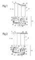
- Figure 1 shows a schematic longitudinal cross-section through a propeller arrangement 2 having a first propeller assembly 4 providing a row of first propellers 6 and a second propeller assembly 8 providing a row of contra-rotating second propellers 10, the propellers of both assemblies being extendable and retractable in a radial direction.
- the degree of extension or retraction of the propellers is controlled by a control system 12 which comprises first 22 and second 24 hydraulic cylinders and first 26 and second 28 pistons which are movable in the respective cylinders.
- the pistons are conveniently formed by the respective roots of the first and the second propellers.
- Each first cylinder and first piston pair forms a first hydraulic chamber 16, and each second cylinder and second piston pair forms a second hydraulic chamber 20, the fluid in the chambers being pressurised by radially outward movement of the pistons.
- the control system 12 allows the first 16 and second 20 chambers to fluidly communicate with each other. More specifically, the first chambers 16 are connected to, or are integral with, a first manifold 42. A first fluid line 44 then extends from the first manifold to a second manifold 45 which connects to, or is integral with, the second chambers 20. A rotating hydraulic coupling 47 on the fluid line allows the first fluid line to cross the interface between that part of the propeller arrangement which rotates with the first propeller assembly 4, and that part which contra-rotates with the second propeller assembly 8. A first valve 40 on the first fluid line allows the first and second chambers to be isolated from each other, if necessary.
- the control system also has a pump 34 which serves as a hydraulic pressure power source.
- a second fluid line 49 extends from the pump to a third manifold 50 which connects to, or is integral with, the second hydraulic cylinders 24 on the opposite sides of the pistons 28 to the second chambers 20.
- a second valve 48 on the second fluid line allows the second cylinders to be isolated from the pump, if necessary.
- the first 6 and second 10 propellers experience a centrifugal force which acts in a radially outwards direction. This force urges the pistons 26, 28 radially outwardly, and generates hydraulic pressure in the chambers 16, 20. However, the pressure generated in the first chambers 16 is greater than the pressure generated in the second chambers 20. A number of factors may contribute to the pressure differential. A first factor can be that the first propellers experience a greater centrifugal force than the second propellers, for example due to relatively greater mass or radial extent of the first propellers. A further factor can be that the first cylinders 22 have a smaller cross-sectional area than the second cylinders 24.
- first valve 40 In a first operating mode of the propeller arrangement, the first valve 40 is open and the second valve 48 is closed.
- the differential pressure in the first chambers 16 is transmitted to the second chambers 20 via a flow of hydraulic fluid (indicated by arrows in Figure 1 ) out of the first chambers, into the first manifold 42, along the first hydraulic line 44, into the second manifold 45, and into the second chambers 20.
- the pressure in the second chambers produces a counter-force which is greater than the centrifugal force acting on the second propellers 10.
- the first propellers 6 extend and the second propellers retract. Following this relative movement, the tips of the extended first propellers are radially further outwards of the tips of the retracted second propellers.
- This offset arrangement results in reduced noise generation and is particularly advantageous in the stages of take-off and climb. More particularly, in these stages, the contraction of the stream tube 60 rearward of the first assembly 4 is increased, and the tip vortices 61 which tend to follow the stream tube from the tips of the first propellers are relatively large. However, the increased crop allows the second propellers to avoid chopping through the vortices.
- the first valve When a desired offset position of the first and second propellers is reached, the first valve can be closed to prevent further radial movement of the propellers.
- the desired offset position is the maximum offset position allowed by movement of the pistons in the cylinders, then it can be unnecessary to close the first valve.
- FIG. 2 shows a schematic longitudinal cross-section of the propeller arrangement in a second operating mode.
- the first valve 40 and the second valve 48 are open and hydraulic fluid pressurised by the pump 34 is transmitted, via the second fluid line 49 and manifold 50, into the second hydraulic cylinders 24, where it acts on the second pistons 20, causing the second propellers 10 to extend.
- This extension reduces the volume of the second chambers 20, increasing the pressure of hydraulic fluid therein to a level which is greater than the pressure generated in the first chambers 16.
- the differential pressure in the second chambers is transmitted to the first chambers via a flow of hydraulic fluid (indicated by arrows in Figure 2 ) which reverses the flow of the first operating mode.
- the pressure in the first chambers now produces a counter-force which is greater than the centrifugal force acting on the first propellers 6, causing the first propellers to retract and the second propellers to extend.
- the tips of the extended second propellers become radially closer to the tips of the retracted first propellers, than in the first operating mode, although still radially inwards of the tips of the first propellers. This position is most suitable for start-up and descent, and for the cruise stage.
- Some flight conditions may require a crop between the maximum and minimum radial offsets shown in Figures 1 and 2 .
- the first valve 40 and second valve 48 may be closed, to prevent further radial movement of the propellers.
- the propeller arrangement allows different degrees of crop to be provided as needed on given flight stages.
- the control system can be contained within the hub of the propeller arrangement and does not require the propellers to be split into telescoping sections. Despite such constraints, the arrangement can provide significant amounts of relative radial movement of the first and second propellers.
Landscapes
- Engineering & Computer Science (AREA)
- Aviation & Aerospace Engineering (AREA)
- Other Liquid Machine Or Engine Such As Wave Power Use (AREA)
- Structures Of Non-Positive Displacement Pumps (AREA)
Abstract
Description
- The present invention relates to a propeller arrangement, particularly a variable diameter propeller arrangement.
- A purpose of a propeller is to convert the rotary motion of an engine into propulsive force, or thrust.
- Increasingly, the design of modern propeller arrangements is influenced by environmental considerations. Such considerations include a need for increased fuel efficiency and reduced noise generation.
- It is known that the efficiency of a traditional single-propeller assembly is increased by the provision of a second propeller assembly rotating in an opposite direction downstream of the first propeller. However, such arrangements, known in the art as contra-rotating propellers, generally suffer from increased noise generation compared to single propeller assembly arrangements.
- It is understood that the increased noise generation is partly due to stream tube contraction and interaction between the second propeller blades and the vortices formed at the tips of the first propeller blades. The tip vortices' position is in line with the stream tube, and follows its contraction from the plane of first row of propellers to the plane of the second row of propellers. However, the amount of stream tube contraction varies, depending on the flight condition, the contraction tending to be greater in higher thrust conditions such as take off.
- If the diameter of the second propeller assembly is larger than the diameter of the stream tube then noise generation will increase as the second row of propellers chop through the vortices. On the other hand, if the second propeller assembly diameter is reduced too far, with the aim of having the second propellers' tips radially inward from the vortices at all flight conditions, the contra-rotating system can loose propulsive efficiency.
-
US 2010/0047068 proposes a contra-rotating propeller engine in which the diameter of the rear propellers is less than the diameter of the front propellers. -
WO05/017351 WO08/8142498 EP A 2009246 proposes a propeller blade pitch control mechanism in which turning of the blade results in a slight outward movement of the blade. - An object of the present invention is to provide a propeller arrangement providing improved fuel efficiency and having reduced noise generation. In particular, an object is to facilitate an arrangement in which a second propeller assembly can have a smaller diameter than a first propeller assembly, the second propeller assembly being rearward of the first propeller assembly.
- In general terms, the present invention provides a propeller arrangement having a first propeller assembly providing a row of first propellers, and a second propeller assembly, rearward of the first propeller assembly, providing a row of second propellers, at least one, and preferably both, of the first and second propellers being radially extendable and retractable. Generally, (i) the first propeller assembly and the second propeller assembly are coaxially aligned, (ii) the first and second propeller assemblies are contra-rotating, and/or (iii) the second propeller assembly has a smaller diameter than the first propeller assembly.
- A first aspect of the present invention provides a propeller arrangement having:
- a first propeller assembly providing a row of first propellers, and a second propeller assembly, rearward of the first propeller assembly, providing a row of second propellers, the first and second propellers being radially extendable and retractable, and
- a control system for controlling the extension and retraction of the first and second propellers;
- wherein the control system is arranged such that when the propellers of one of the first and second propeller assemblies extend, the propellers of the other of the first and second assemblies retract.
- Different diameters between the propeller assemblies can be described in terms of "radial offset", i.e. the difference in radial position between the tips of the first and second propellers. When, as is typical, the first propeller assembly has a larger diameter than the second propeller assembly, the difference in the radial distance between the tips of the first propeller blades and the tips of the second propeller blades can be termed the "crop".
- Advantageously, the diameters of the first and second propeller assemblies may be varied in relation to each other. In this way, the noise generation and the efficiency of the propeller assembly may be varied, for example, according to the requirements of the different stages of aircraft flight.
- A typical aircraft flight has a number of stages including: start-up, take-off, climb, cruise, descent, and landing. The operating conditions have different thrust requirements, which are closely correlated to stream tube contraction. Larger thrusts generally produce greater stream tube contractions, meaning that larger radial offsets between the tips of the front and rear rotor will be required.
- The propeller arrangement facilitates a contra-rotating arrangement in which both propeller assembly diameters are able to vary dependent on stream tube contraction. The first propeller effectively increases the stream tube diameter when it increases its own tip radial position and the rear propeller decreases its own tip radial position. The relative motion of the two propellers can ensure that the tips of the second propellers do not interact with the vortices formed at the tips of the first propellers, i.e. by having the tips of the second propellers inward of the vortices at the plane of the second propeller assembly. However, because the crop is variable, loss in propulsive efficiency can be minimised or reduced across different flight stages, without substantially increasing noise production.
- A further advantage of the present invention is that a desired crop can be achieved by relatively small, and opposing, radial movements of both assemblies, rather than a relatively large radial movement of only one assembly.
- For example, in order to achieve a crop of 100 mm between the propeller assemblies, the first propellers may extend by 50 mm and the second propellers may retract by 50 mm. The reduced radial displacement of the propellers permits the use of control systems having components with reduced actuation distances. Such components can then be easier to accommodate in e.g. the limited space of a hub of a propeller arrangement.
- The propeller arrangement may have any one or, to the extent that they are compatible, any combination of the following optional features.
- Preferably, the first propeller assembly and the second propeller assembly are coaxially aligned. The first and second propeller assemblies are typically contra-rotating. The second propeller assembly typically has a smaller diameter than the first propeller assembly.
- The control system may be further arranged such that the maximum extension of the first propellers and the maximum retraction of the second propellers provides a crop which is at least 5%, and preferably at least 10%, of the radius of the extended first propellers. The control system may be further arranged such that the maximum retraction of the first propellers and the maximum extension of the second propellers provides a crop which is at most 2%, and preferably at most 1 %, of the radius of the retracted first propellers.
- Preferably, the control system is hydraulically powered.
- For example, the control system may comprise a plurality of first hydraulic chambers operatively connected to respective roots of the first propellers and a plurality of second hydraulic chambers operatively connected to respective roots of the second propellers, the hydraulic chambers being arranged such that varying the hydraulic pressure therein applies a radial force on the respective propellers, and the control system allowing hydraulic pressure to be transmitted between the first and second chambers, whereby, when the propellers of one of the first and second propeller assemblies extend, the pressure of hydraulic fluid in the corresponding hydraulic chambers varies and is transmitted to the hydraulic chambers of the other of the first and second propeller assemblies, causing the propellers of the other of the first and second assemblies to retract.
- Advantageously, as the hydraulic chambers are operatively connected to the roots of the propellers, telescopic arrangements for varying propeller length, in which the propellers are split into sections, can be avoided. Thus, unlike the rotor blades of
WO05/017351 WO08/8142498 - Preferably, the hydraulic chambers are arranged such that increasing the hydraulic pressure in the hydraulic chambers applies a radially inward force on the respective propellers.
- Each hydraulic chamber can be provided by a respective hydraulic cylinder and piston arrangement. Conveniently, the roots of the propellers may form the pistons of the cylinder and piston arrangements.
- Preferably, the control system provides a first operating mode in which the first propellers extend under centrifugal force, whereby the pressure of hydraulic fluid in the first chambers varies and is transmitted to hydraulic fluid in the second chambers, causing the second propellers to retract against centrifugal force acting thereon. The tips of the first propellers can thus be extended radially further outwards of the tips of the second propellers, i.e. to increase the radial offset between the first and the second propeller assemblies. This can reduce noise generation through a reduced interaction of the tips of the second propellers with vortices formed at the tips of the first propellers. The first operating mode is generally for flight conditions with higher thrust requirements, such as take-off and climb. In these conditions, the stream tube contraction tends to be greater, and a larger radial offset between the tips of the first and second propellers is desirable.
- Advantageously, the transmission of hydraulic pressure enables the centrifugal force acting on the first propellers to power retraction of the second propellers. This can reduce the quantity and complexity of components in the control system. It also allows the propellers to respond automatically when the first operating mode is implemented.
- The control system may further comprise a hydraulic pressure power source which is operatively connected to the roots of the second propellers, the control system providing a second operating mode in which the hydraulic pressure power source operates on the second propellers to cause them to extend, whereby the pressure of hydraulic fluid in the second chambers varies and is transmitted to hydraulic fluid in the first chambers, causing the first propellers to retract against centrifugal force acting thereon. The tips of the second propellers can thus be extended radially towards the tips of the first propellers, i.e. to reduce the radial offset between the first and the second propeller assemblies. The second operating mode is generally for flight conditions with lower thrust requirements, such as start up, cruise and descent. In these conditions, the stream tube contraction tends to be less, so that the tips of the second propellers are preferably only slightly radially inwards of the tips of the first propellers and propulsive efficiency is improved.
- Together, the first and second operating modes can be used to achieve reduce noise levels and increase fuel efficiency.
- Preferably, the control system provides a third operating mode in which the first hydraulic chambers are isolated from the second hydraulic chambers preventing hydraulic pressure being transmitted therebetween. This operating mode can be used to fix the radial positions of the propellers.
- As an alternative to hydraulic power, the control system may be electrically powered, e.g. with electrically powered actuators at the roots of the propellers for radially moving the propellers, and a control unit which sends electrical control signals to the actuators.
- A second aspect of the present invention provides a turboprop engine having a propeller arrangement of the first aspect.
- A third aspect of the present invention provides a method of operating an engine comprising a propeller arrangement having a first propeller assembly providing a row of first propellers, and a second propeller assembly providing a row of (typically contra-rotating) second propellers, the second propeller assembly being coaxial with and rearward of the first assembly, the method comprising the step of:
- at a take-off or climb stage of a flight cycle, extending the first propellers and/or retracting the second propellers such that the tips of the first propellers are moved radially further outward of the tips of the second propellers.
- The method may have any one or, to the extent that they are compatible, any combination of the following optional features.
- The method may further comprise the step of:
- at a cruise or descent stage of the flight cycle, retracting the first propellers and/or extending the second propellers such that the radial distances between the tips of the first propellers and the tips of the second propellers is reduced.
- Preferably the engine, which is typically a turboprop engine, comprises a propeller arrangement according to the first aspect. In this way, when the propellers of one of the first and second propeller assemblies extend, the propellers of the other of the first and second assemblies retract. However, other propeller arrangements are possible, e.g. ones in which only the first propellers are extendable and retractable or only the second propellers are extendable and retractable.
- Embodiments of the invention will now be described by way of example with reference to the accompanying drawings in which:
-
Figure 1 shows a schematic longitudinal cross-section of a propeller arrangement in a first operating mode; and -
Figure 2 shows a schematic longitudinal cross-section of the propeller arrangement in a second operating mode. -
Figure 1 shows a schematic longitudinal cross-section through apropeller arrangement 2 having a first propeller assembly 4 providing a row of first propellers 6 and asecond propeller assembly 8 providing a row of contra-rotatingsecond propellers 10, the propellers of both assemblies being extendable and retractable in a radial direction. The degree of extension or retraction of the propellers is controlled by acontrol system 12 which comprises first 22 and second 24 hydraulic cylinders and first 26 and second 28 pistons which are movable in the respective cylinders. The pistons are conveniently formed by the respective roots of the first and the second propellers. Each first cylinder and first piston pair forms a firsthydraulic chamber 16, and each second cylinder and second piston pair forms a secondhydraulic chamber 20, the fluid in the chambers being pressurised by radially outward movement of the pistons. - The
control system 12 allows the first 16 and second 20 chambers to fluidly communicate with each other. More specifically, thefirst chambers 16 are connected to, or are integral with, afirst manifold 42. Afirst fluid line 44 then extends from the first manifold to asecond manifold 45 which connects to, or is integral with, thesecond chambers 20. A rotatinghydraulic coupling 47 on the fluid line allows the first fluid line to cross the interface between that part of the propeller arrangement which rotates with the first propeller assembly 4, and that part which contra-rotates with thesecond propeller assembly 8. Afirst valve 40 on the first fluid line allows the first and second chambers to be isolated from each other, if necessary. - The control system also has a
pump 34 which serves as a hydraulic pressure power source. Asecond fluid line 49 extends from the pump to athird manifold 50 which connects to, or is integral with, the secondhydraulic cylinders 24 on the opposite sides of thepistons 28 to thesecond chambers 20. Asecond valve 48 on the second fluid line allows the second cylinders to be isolated from the pump, if necessary. - On rotation of the propeller assemblies, the first 6 and second 10 propellers experience a centrifugal force which acts in a radially outwards direction. This force urges the
pistons chambers first chambers 16 is greater than the pressure generated in thesecond chambers 20. A number of factors may contribute to the pressure differential. A first factor can be that the first propellers experience a greater centrifugal force than the second propellers, for example due to relatively greater mass or radial extent of the first propellers. A further factor can be that thefirst cylinders 22 have a smaller cross-sectional area than thesecond cylinders 24. - In a first operating mode of the propeller arrangement, the
first valve 40 is open and thesecond valve 48 is closed. The differential pressure in thefirst chambers 16 is transmitted to thesecond chambers 20 via a flow of hydraulic fluid (indicated by arrows inFigure 1 ) out of the first chambers, into thefirst manifold 42, along the firsthydraulic line 44, into thesecond manifold 45, and into thesecond chambers 20. The pressure in the second chambers produces a counter-force which is greater than the centrifugal force acting on thesecond propellers 10. Thus the first propellers 6 extend and the second propellers retract. Following this relative movement, the tips of the extended first propellers are radially further outwards of the tips of the retracted second propellers. This offset arrangement results in reduced noise generation and is particularly advantageous in the stages of take-off and climb. More particularly, in these stages, the contraction of thestream tube 60 rearward of the first assembly 4 is increased, and thetip vortices 61 which tend to follow the stream tube from the tips of the first propellers are relatively large. However, the increased crop allows the second propellers to avoid chopping through the vortices. - When a desired offset position of the first and second propellers is reached, the first valve can be closed to prevent further radial movement of the propellers. Alternatively, if the desired offset position is the maximum offset position allowed by movement of the pistons in the cylinders, then it can be unnecessary to close the first valve.
-
Figure 2 shows a schematic longitudinal cross-section of the propeller arrangement in a second operating mode. Thefirst valve 40 and thesecond valve 48 are open and hydraulic fluid pressurised by thepump 34 is transmitted, via thesecond fluid line 49 andmanifold 50, into the secondhydraulic cylinders 24, where it acts on thesecond pistons 20, causing thesecond propellers 10 to extend. This extension reduces the volume of thesecond chambers 20, increasing the pressure of hydraulic fluid therein to a level which is greater than the pressure generated in thefirst chambers 16. The differential pressure in the second chambers is transmitted to the first chambers via a flow of hydraulic fluid (indicated by arrows inFigure 2 ) which reverses the flow of the first operating mode. The pressure in the first chambers now produces a counter-force which is greater than the centrifugal force acting on the first propellers 6, causing the first propellers to retract and the second propellers to extend. As a result, the tips of the extended second propellers become radially closer to the tips of the retracted first propellers, than in the first operating mode, although still radially inwards of the tips of the first propellers. This position is most suitable for start-up and descent, and for the cruise stage. - Some flight conditions may require a crop between the maximum and minimum radial offsets shown in
Figures 1 and 2 . Thus when a desired crop is achieved, thefirst valve 40 andsecond valve 48 may be closed, to prevent further radial movement of the propellers. - Advantageously, the propeller arrangement allows different degrees of crop to be provided as needed on given flight stages. The control system can be contained within the hub of the propeller arrangement and does not require the propellers to be split into telescoping sections. Despite such constraints, the arrangement can provide significant amounts of relative radial movement of the first and second propellers.
- While the invention has been described in conjunction with the exemplary embodiments described above, many equivalent modifications and variations will be apparent to those skilled in the art when given this disclosure. Accordingly, the exemplary embodiments of the invention set forth above are considered to be illustrative and not limiting. Various changes to the described embodiments may be made without departing from the spirit and scope of the invention.
- All references referred to above are hereby incorporated by reference.
Claims (15)
- A propeller arrangement (2) having:a first propeller assembly (4) providing a row of first propellers (6), and a second propeller assembly (8), rearward of the first propeller assembly, providing a row of second propellers (10), the first (6) and second (10) propellers being radially extendable and retractable, anda control system (12) for controlling the extension and retraction of the first (6) and second (10) propellers;wherein the control system (12) is arranged such that when the propellers (6, 10) of one of the first (4) and second (8) propeller assemblies extend, the propellers of the other of the first and second assemblies retract.
- A propeller arrangement (2) according to claim 1, wherein the first propeller assembly (4) and the second propeller assembly (8) are contra-rotating.
- A propeller arrangement (2) according to claim 1 or 2, wherein the control system is hydraulically powered.
- A propeller arrangement according to claim 3, wherein the control system (12) comprises a plurality of first hydraulic chambers (16) operatively connected to respective roots of the first propellers (6) and a plurality of second hydraulic chambers (20) operatively connected to respective roots of the second propellers (10), the hydraulic chambers (16, 20) being arranged such that varying the hydraulic pressure therein applies a radial force on the respective propellers, and the control system (12) allowing hydraulic pressure to be transmitted between the first (16) and second (20) chambers, whereby, when the propellers (6, 10) of one of the first (4) and second (8) propeller assemblies extend, the pressure of hydraulic fluid in the corresponding hydraulic chambers (16, 20) varies and is transmitted to the hydraulic chambers of the other of the first and second propeller assemblies, causing the propellers of the other of the first and second assemblies to retract.
- A propeller arrangement according to claim 4, wherein the hydraulic chambers are arranged such that increasing the hydraulic pressure in the hydraulic chambers applies a radially inward force on the respective propellers.
- A propeller arrangement according to claim 4 or 5, wherein each hydraulic chamber (16, 20) is provided by a respective hydraulic cylinder (22, 24) and piston (26, 28) arrangement.
- A propeller arrangement (2) according to claim 6, wherein the roots of the propellers form the pistons (26, 28) of the cylinder (22, 24) and piston arrangements.
- A propeller arrangement (2) according to any one of claims 4 to 7, wherein the control system (12) provides a first operating mode in which the first propellers (6) extend under centrifugal force, whereby the pressure of hydraulic fluid in the first chambers (16) varies and is transmitted to hydraulic fluid in the second chambers (20), causing the second propellers (10) to retract against centrifugal force acting thereon.
- A propeller arrangement (2) according to claim 8, wherein, under the first operating mode, the tips of the first propellers (6) are extended radially further outwards of the tips of the second propellers (10).
- A propeller arrangement (2) according to any one of claims 4 to 9, wherein the control system (12) further comprises a hydraulic pressure power source (34) which is operatively connected to the roots of the second propellers (10), the control system (12) providing a second operating mode in which the hydraulic pressure power source (34) operates on the second propellers (10) to cause them to extend, whereby the pressure of hydraulic fluid in the second chambers (20) varies and is transmitted to hydraulic fluid in the first chambers (16), causing the first propellers (6) to retract against centrifugal force acting thereon.
- A propeller arrangement (2) according to claim 10, wherein, under the second operating mode, the tips of the second propellers (10) are extended radially towards the tips of the first propellers (6).
- A propeller arrangement (2) according to any one of claims 4 to 11, wherein the control system (12) provides a third operating mode in which the first hydraulic chambers (16) are isolated (40) from the second hydraulic chambers (20), preventing hydraulic pressure being transmitted therebetween.
- A propeller arrangement (2) according to claim 1 or 2, wherein the control system (12) is electrically powered.
- A method of operating an engine comprising a propeller arrangement having a first propeller assembly providing a row of first propellers, and a second propeller assembly providing a row of second propellers, the second propeller assembly being coaxial with and rearward of the first assembly, the method comprising the step of:at a take-off or climb stage of a flight cycle, extending the first propellers and/or retracting the second propellers such that the tips of the first propellers are moved radially further outward of the tips of the second propellers.
- The method of claim 14, further comprising the step of:at a cruise or descent stage of the flight cycle, retracting the first propellers and/or extending the second propellers such that the radial distances between the tips of the first propellers and the tips of the second propellers is reduced.
Applications Claiming Priority (1)
| Application Number | Priority Date | Filing Date | Title |
|---|---|---|---|
| GBGB1003858.6A GB201003858D0 (en) | 2010-03-09 | 2010-03-09 | Propeller arrangement |
Publications (3)
| Publication Number | Publication Date |
|---|---|
| EP2368795A2 true EP2368795A2 (en) | 2011-09-28 |
| EP2368795A3 EP2368795A3 (en) | 2014-04-02 |
| EP2368795B1 EP2368795B1 (en) | 2017-04-05 |
Family
ID=42136670
Family Applications (1)
| Application Number | Title | Priority Date | Filing Date |
|---|---|---|---|
| EP11154441.7A Not-in-force EP2368795B1 (en) | 2010-03-09 | 2011-02-15 | Propeller arrangement |
Country Status (3)
| Country | Link |
|---|---|
| US (1) | US8770935B2 (en) |
| EP (1) | EP2368795B1 (en) |
| GB (1) | GB201003858D0 (en) |
Cited By (3)
| Publication number | Priority date | Publication date | Assignee | Title |
|---|---|---|---|---|
| WO2013045859A1 (en) * | 2011-09-29 | 2013-04-04 | Snecma | Blade for a fan of a turbomachine, notably of the unducted fan type, corresponding fan and corresponding turbomachine |
| EP2596247B1 (en) * | 2010-07-23 | 2015-09-02 | Snecma | Turboengine with two counterrotating open rotors (cror) |
| FR3081435A1 (en) * | 2018-05-24 | 2019-11-29 | Safran Aircraft Engines | AIRCRAFT TURBOMACHINE HAVING ROTARY AND NON-CARNETIC PROPELLERS |
Families Citing this family (2)
| Publication number | Priority date | Publication date | Assignee | Title |
|---|---|---|---|---|
| US20210009263A1 (en) * | 2019-07-12 | 2021-01-14 | Dotterel Technologies Limited | Rotor system |
| CN118953669B (en) * | 2024-10-16 | 2025-03-14 | 中国空气动力研究与发展中心低速空气动力研究所 | A device for reducing helicopter blade vortex interference |
Citations (4)
| Publication number | Priority date | Publication date | Assignee | Title |
|---|---|---|---|---|
| WO2005017351A1 (en) | 2003-07-29 | 2005-02-24 | General Electric Company | Variable diameter rotor |
| WO2008142498A1 (en) | 2007-05-24 | 2008-11-27 | Georgian Technical University (Gtu) | Variable-diameter rotor with centrifugal forces compensation mechanism |
| EP2009246A2 (en) | 2007-06-28 | 2008-12-31 | Rolls-Royce plc | A blade mounting |
| US20100047068A1 (en) | 2007-02-10 | 2010-02-25 | Rolls-Royce Plc | Aeroengine |
Family Cites Families (7)
| Publication number | Priority date | Publication date | Assignee | Title |
|---|---|---|---|---|
| FR878743A (en) * | 1941-09-19 | 1943-01-28 | Improvements to mobile position control devices | |
| US2979288A (en) * | 1959-01-15 | 1961-04-11 | Klein Albert | Aircraft propeller arrangement and means for elongating same |
| US3814351A (en) * | 1972-12-06 | 1974-06-04 | United Aircraft Corp | Coaxial rotor yaw control |
| US4978286A (en) * | 1989-10-17 | 1990-12-18 | The United States Of America As Represented By The Secretary Of The Army | Variable cycle engine passive mechanism |
| DE4420219A1 (en) * | 1994-06-06 | 1995-12-07 | Stemme Gmbh & Co Kg | Fixed wing aircraft with two coaxial propellers of different diameters |
| US7071578B1 (en) * | 2002-01-10 | 2006-07-04 | Mitsubishi Heavy Industries, Ltd. | Wind turbine provided with a controller for adjusting active annular plane area and the operating method thereof |
| US7004427B2 (en) * | 2002-09-09 | 2006-02-28 | Gerbino Allen J | Retractable lifting blades for aircraft |
-
2010
- 2010-03-09 GB GBGB1003858.6A patent/GB201003858D0/en not_active Ceased
-
2011
- 2011-02-15 US US13/027,653 patent/US8770935B2/en active Active
- 2011-02-15 EP EP11154441.7A patent/EP2368795B1/en not_active Not-in-force
Patent Citations (4)
| Publication number | Priority date | Publication date | Assignee | Title |
|---|---|---|---|---|
| WO2005017351A1 (en) | 2003-07-29 | 2005-02-24 | General Electric Company | Variable diameter rotor |
| US20100047068A1 (en) | 2007-02-10 | 2010-02-25 | Rolls-Royce Plc | Aeroengine |
| WO2008142498A1 (en) | 2007-05-24 | 2008-11-27 | Georgian Technical University (Gtu) | Variable-diameter rotor with centrifugal forces compensation mechanism |
| EP2009246A2 (en) | 2007-06-28 | 2008-12-31 | Rolls-Royce plc | A blade mounting |
Cited By (7)
| Publication number | Priority date | Publication date | Assignee | Title |
|---|---|---|---|---|
| EP2596247B1 (en) * | 2010-07-23 | 2015-09-02 | Snecma | Turboengine with two counterrotating open rotors (cror) |
| WO2013045859A1 (en) * | 2011-09-29 | 2013-04-04 | Snecma | Blade for a fan of a turbomachine, notably of the unducted fan type, corresponding fan and corresponding turbomachine |
| FR2980818A1 (en) * | 2011-09-29 | 2013-04-05 | Snecma | BLADE FOR A TURBOMACHINE PROPELLER, IN PARTICULAR A NON-CARBENE BLOWER, PROPELLER AND TURBOMACHINE CORRESPONDING. |
| RU2606787C2 (en) * | 2011-09-29 | 2017-01-10 | Снекма | Turbine machine propeller blade, particularly fan without fairing, and corresponding propeller and turbo machine |
| US9630704B2 (en) | 2011-09-29 | 2017-04-25 | Snecma | Blade for a fan of a turbomachine, notably of the unducted fan type, corresponding fan and corresponding turbomachine |
| FR3081435A1 (en) * | 2018-05-24 | 2019-11-29 | Safran Aircraft Engines | AIRCRAFT TURBOMACHINE HAVING ROTARY AND NON-CARNETIC PROPELLERS |
| US11021230B2 (en) | 2018-05-24 | 2021-06-01 | Safran Aircraft Engines | Aircraft turbine engine with a pair of rotating and non-ducted propellers |
Also Published As
| Publication number | Publication date |
|---|---|
| US8770935B2 (en) | 2014-07-08 |
| EP2368795B1 (en) | 2017-04-05 |
| US20110223020A1 (en) | 2011-09-15 |
| GB201003858D0 (en) | 2010-04-21 |
| EP2368795A3 (en) | 2014-04-02 |
Similar Documents
| Publication | Publication Date | Title |
|---|---|---|
| CN109641647B (en) | Tiltrotor propulsion system for aircraft | |
| CN109661345B (en) | Tilt rotor propulsion system for aircraft and aircraft with such system | |
| US10119409B2 (en) | System for changing the pitch of the contra-rotating propellers of a turboshaft engine | |
| US11111029B2 (en) | System and method for operating a boundary layer ingestion fan | |
| US8770935B2 (en) | Propeller arrangement | |
| CN107878733B (en) | Translating fan blades for aircraft tail mounted fan assemblies | |
| US8256709B2 (en) | Aircraft with tail propeller-engine layout | |
| EP1992807B1 (en) | Variable geometry nacelle for an aircraft engine and corresponding operating method | |
| JP6082939B2 (en) | Turbo engine with aircraft propeller (s) and propeller pitch changing system | |
| EP2551506A2 (en) | Thrust reverser for a turbofan engine | |
| IT201900010929A1 (en) | PROPELLER GROUP AND PITCH CONTROL UNIT | |
| US20130115083A1 (en) | Turbine engine having two unducted propellers | |
| CN105579342B (en) | Means for supplying hydraulic fluid to a hydraulic cylinder and means for controlling blade pitch of a turbine engine propeller comprising the hydraulic cylinder | |
| CN106240829B (en) | Nacelle inlet with angled or curved aft bulkhead | |
| JP2017095081A (en) | Systems and methods for controlling propeller pitch | |
| BR112015002317B1 (en) | BYPASS TURBINE ENGINE | |
| US11511837B2 (en) | Hybrid propulsor for watercraft | |
| EP2351925A2 (en) | Back-up featherer | |
| US8721283B2 (en) | Pitch change apparatus | |
| EP3203085A1 (en) | Adjustable pitch propeller or gte fan with redundant actuators | |
| US10479483B2 (en) | Pitch control assembly and propeller assembly and method of adjusting pitch | |
| US10408127B2 (en) | Turbomachine provided with an assembly for controlling the pitch variation of a propeller | |
| US9556744B2 (en) | Turbomachine with fan(s) for aircraft, with mobile jet nozzle | |
| US20220289362A1 (en) | Turbomachine module equipped with a system for changing the pitch of the blades of a propeller and with a device for feathering the blades | |
| CN117615966A (en) | System for changing the pitch of the blades of a turbomachine propeller |
Legal Events
| Date | Code | Title | Description |
|---|---|---|---|
| PUAI | Public reference made under article 153(3) epc to a published international application that has entered the european phase |
Free format text: ORIGINAL CODE: 0009012 |
|
| AK | Designated contracting states |
Kind code of ref document: A2 Designated state(s): AL AT BE BG CH CY CZ DE DK EE ES FI FR GB GR HR HU IE IS IT LI LT LU LV MC MK MT NL NO PL PT RO RS SE SI SK SM TR |
|
| AX | Request for extension of the european patent |
Extension state: BA ME |
|
| PUAL | Search report despatched |
Free format text: ORIGINAL CODE: 0009013 |
|
| AK | Designated contracting states |
Kind code of ref document: A3 Designated state(s): AL AT BE BG CH CY CZ DE DK EE ES FI FR GB GR HR HU IE IS IT LI LT LU LV MC MK MT NL NO PL PT RO RS SE SI SK SM TR |
|
| AX | Request for extension of the european patent |
Extension state: BA ME |
|
| RIC1 | Information provided on ipc code assigned before grant |
Ipc: B64C 11/48 20060101ALI20140221BHEP Ipc: B64C 11/00 20060101AFI20140221BHEP |
|
| 17P | Request for examination filed |
Effective date: 20140912 |
|
| RBV | Designated contracting states (corrected) |
Designated state(s): AL AT BE BG CH CY CZ DE DK EE ES FI FR GB GR HR HU IE IS IT LI LT LU LV MC MK MT NL NO PL PT RO RS SE SI SK SM TR |
|
| RAP1 | Party data changed (applicant data changed or rights of an application transferred) |
Owner name: ROLLS-ROYCE PLC |
|
| GRAP | Despatch of communication of intention to grant a patent |
Free format text: ORIGINAL CODE: EPIDOSNIGR1 |
|
| STAA | Information on the status of an ep patent application or granted ep patent |
Free format text: STATUS: GRANT OF PATENT IS INTENDED |
|
| GRAS | Grant fee paid |
Free format text: ORIGINAL CODE: EPIDOSNIGR3 |
|
| INTG | Intention to grant announced |
Effective date: 20170112 |
|
| GRAA | (expected) grant |
Free format text: ORIGINAL CODE: 0009210 |
|
| STAA | Information on the status of an ep patent application or granted ep patent |
Free format text: STATUS: THE PATENT HAS BEEN GRANTED |
|
| AK | Designated contracting states |
Kind code of ref document: B1 Designated state(s): AL AT BE BG CH CY CZ DE DK EE ES FI FR GB GR HR HU IE IS IT LI LT LU LV MC MK MT NL NO PL PT RO RS SE SI SK SM TR |
|
| REG | Reference to a national code |
Ref country code: GB Ref legal event code: FG4D |
|
| REG | Reference to a national code |
Ref country code: CH Ref legal event code: EP |
|
| REG | Reference to a national code |
Ref country code: AT Ref legal event code: REF Ref document number: 881543 Country of ref document: AT Kind code of ref document: T Effective date: 20170415 |
|
| REG | Reference to a national code |
Ref country code: IE Ref legal event code: FG4D |
|
| REG | Reference to a national code |
Ref country code: DE Ref legal event code: R096 Ref document number: 602011036583 Country of ref document: DE |
|
| REG | Reference to a national code |
Ref country code: NL Ref legal event code: MP Effective date: 20170405 |
|
| REG | Reference to a national code |
Ref country code: LT Ref legal event code: MG4D |
|
| REG | Reference to a national code |
Ref country code: AT Ref legal event code: MK05 Ref document number: 881543 Country of ref document: AT Kind code of ref document: T Effective date: 20170405 |
|
| PG25 | Lapsed in a contracting state [announced via postgrant information from national office to epo] |
Ref country code: NL Free format text: LAPSE BECAUSE OF FAILURE TO SUBMIT A TRANSLATION OF THE DESCRIPTION OR TO PAY THE FEE WITHIN THE PRESCRIBED TIME-LIMIT Effective date: 20170405 |
|
| PG25 | Lapsed in a contracting state [announced via postgrant information from national office to epo] |
Ref country code: GR Free format text: LAPSE BECAUSE OF FAILURE TO SUBMIT A TRANSLATION OF THE DESCRIPTION OR TO PAY THE FEE WITHIN THE PRESCRIBED TIME-LIMIT Effective date: 20170706 Ref country code: HR Free format text: LAPSE BECAUSE OF FAILURE TO SUBMIT A TRANSLATION OF THE DESCRIPTION OR TO PAY THE FEE WITHIN THE PRESCRIBED TIME-LIMIT Effective date: 20170405 Ref country code: AT Free format text: LAPSE BECAUSE OF FAILURE TO SUBMIT A TRANSLATION OF THE DESCRIPTION OR TO PAY THE FEE WITHIN THE PRESCRIBED TIME-LIMIT Effective date: 20170405 Ref country code: NO Free format text: LAPSE BECAUSE OF FAILURE TO SUBMIT A TRANSLATION OF THE DESCRIPTION OR TO PAY THE FEE WITHIN THE PRESCRIBED TIME-LIMIT Effective date: 20170705 Ref country code: FI Free format text: LAPSE BECAUSE OF FAILURE TO SUBMIT A TRANSLATION OF THE DESCRIPTION OR TO PAY THE FEE WITHIN THE PRESCRIBED TIME-LIMIT Effective date: 20170405 Ref country code: ES Free format text: LAPSE BECAUSE OF FAILURE TO SUBMIT A TRANSLATION OF THE DESCRIPTION OR TO PAY THE FEE WITHIN THE PRESCRIBED TIME-LIMIT Effective date: 20170405 Ref country code: LT Free format text: LAPSE BECAUSE OF FAILURE TO SUBMIT A TRANSLATION OF THE DESCRIPTION OR TO PAY THE FEE WITHIN THE PRESCRIBED TIME-LIMIT Effective date: 20170405 |
|
| PG25 | Lapsed in a contracting state [announced via postgrant information from national office to epo] |
Ref country code: PL Free format text: LAPSE BECAUSE OF FAILURE TO SUBMIT A TRANSLATION OF THE DESCRIPTION OR TO PAY THE FEE WITHIN THE PRESCRIBED TIME-LIMIT Effective date: 20170405 Ref country code: BG Free format text: LAPSE BECAUSE OF FAILURE TO SUBMIT A TRANSLATION OF THE DESCRIPTION OR TO PAY THE FEE WITHIN THE PRESCRIBED TIME-LIMIT Effective date: 20170705 Ref country code: IS Free format text: LAPSE BECAUSE OF FAILURE TO SUBMIT A TRANSLATION OF THE DESCRIPTION OR TO PAY THE FEE WITHIN THE PRESCRIBED TIME-LIMIT Effective date: 20170805 Ref country code: RS Free format text: LAPSE BECAUSE OF FAILURE TO SUBMIT A TRANSLATION OF THE DESCRIPTION OR TO PAY THE FEE WITHIN THE PRESCRIBED TIME-LIMIT Effective date: 20170405 Ref country code: SE Free format text: LAPSE BECAUSE OF FAILURE TO SUBMIT A TRANSLATION OF THE DESCRIPTION OR TO PAY THE FEE WITHIN THE PRESCRIBED TIME-LIMIT Effective date: 20170405 Ref country code: LV Free format text: LAPSE BECAUSE OF FAILURE TO SUBMIT A TRANSLATION OF THE DESCRIPTION OR TO PAY THE FEE WITHIN THE PRESCRIBED TIME-LIMIT Effective date: 20170405 |
|
| REG | Reference to a national code |
Ref country code: DE Ref legal event code: R097 Ref document number: 602011036583 Country of ref document: DE |
|
| PG25 | Lapsed in a contracting state [announced via postgrant information from national office to epo] |
Ref country code: RO Free format text: LAPSE BECAUSE OF FAILURE TO SUBMIT A TRANSLATION OF THE DESCRIPTION OR TO PAY THE FEE WITHIN THE PRESCRIBED TIME-LIMIT Effective date: 20170405 Ref country code: DK Free format text: LAPSE BECAUSE OF FAILURE TO SUBMIT A TRANSLATION OF THE DESCRIPTION OR TO PAY THE FEE WITHIN THE PRESCRIBED TIME-LIMIT Effective date: 20170405 Ref country code: EE Free format text: LAPSE BECAUSE OF FAILURE TO SUBMIT A TRANSLATION OF THE DESCRIPTION OR TO PAY THE FEE WITHIN THE PRESCRIBED TIME-LIMIT Effective date: 20170405 Ref country code: SK Free format text: LAPSE BECAUSE OF FAILURE TO SUBMIT A TRANSLATION OF THE DESCRIPTION OR TO PAY THE FEE WITHIN THE PRESCRIBED TIME-LIMIT Effective date: 20170405 Ref country code: CZ Free format text: LAPSE BECAUSE OF FAILURE TO SUBMIT A TRANSLATION OF THE DESCRIPTION OR TO PAY THE FEE WITHIN THE PRESCRIBED TIME-LIMIT Effective date: 20170405 |
|
| PLBE | No opposition filed within time limit |
Free format text: ORIGINAL CODE: 0009261 |
|
| STAA | Information on the status of an ep patent application or granted ep patent |
Free format text: STATUS: NO OPPOSITION FILED WITHIN TIME LIMIT |
|
| REG | Reference to a national code |
Ref country code: FR Ref legal event code: PLFP Year of fee payment: 8 |
|
| PG25 | Lapsed in a contracting state [announced via postgrant information from national office to epo] |
Ref country code: SM Free format text: LAPSE BECAUSE OF FAILURE TO SUBMIT A TRANSLATION OF THE DESCRIPTION OR TO PAY THE FEE WITHIN THE PRESCRIBED TIME-LIMIT Effective date: 20170405 Ref country code: IT Free format text: LAPSE BECAUSE OF FAILURE TO SUBMIT A TRANSLATION OF THE DESCRIPTION OR TO PAY THE FEE WITHIN THE PRESCRIBED TIME-LIMIT Effective date: 20170405 |
|
| 26N | No opposition filed |
Effective date: 20180108 |
|
| PG25 | Lapsed in a contracting state [announced via postgrant information from national office to epo] |
Ref country code: SI Free format text: LAPSE BECAUSE OF FAILURE TO SUBMIT A TRANSLATION OF THE DESCRIPTION OR TO PAY THE FEE WITHIN THE PRESCRIBED TIME-LIMIT Effective date: 20170405 |
|
| REG | Reference to a national code |
Ref country code: CH Ref legal event code: PL |
|
| PG25 | Lapsed in a contracting state [announced via postgrant information from national office to epo] |
Ref country code: MC Free format text: LAPSE BECAUSE OF FAILURE TO SUBMIT A TRANSLATION OF THE DESCRIPTION OR TO PAY THE FEE WITHIN THE PRESCRIBED TIME-LIMIT Effective date: 20170405 |
|
| REG | Reference to a national code |
Ref country code: IE Ref legal event code: MM4A |
|
| REG | Reference to a national code |
Ref country code: BE Ref legal event code: MM Effective date: 20180228 |
|
| PG25 | Lapsed in a contracting state [announced via postgrant information from national office to epo] |
Ref country code: CH Free format text: LAPSE BECAUSE OF NON-PAYMENT OF DUE FEES Effective date: 20180228 Ref country code: LI Free format text: LAPSE BECAUSE OF NON-PAYMENT OF DUE FEES Effective date: 20180228 Ref country code: LU Free format text: LAPSE BECAUSE OF NON-PAYMENT OF DUE FEES Effective date: 20180215 |
|
| PG25 | Lapsed in a contracting state [announced via postgrant information from national office to epo] |
Ref country code: IE Free format text: LAPSE BECAUSE OF NON-PAYMENT OF DUE FEES Effective date: 20180215 |
|
| PG25 | Lapsed in a contracting state [announced via postgrant information from national office to epo] |
Ref country code: BE Free format text: LAPSE BECAUSE OF NON-PAYMENT OF DUE FEES Effective date: 20180228 |
|
| PG25 | Lapsed in a contracting state [announced via postgrant information from national office to epo] |
Ref country code: MT Free format text: LAPSE BECAUSE OF NON-PAYMENT OF DUE FEES Effective date: 20180215 |
|
| PG25 | Lapsed in a contracting state [announced via postgrant information from national office to epo] |
Ref country code: TR Free format text: LAPSE BECAUSE OF FAILURE TO SUBMIT A TRANSLATION OF THE DESCRIPTION OR TO PAY THE FEE WITHIN THE PRESCRIBED TIME-LIMIT Effective date: 20170405 |
|
| PG25 | Lapsed in a contracting state [announced via postgrant information from national office to epo] |
Ref country code: PT Free format text: LAPSE BECAUSE OF FAILURE TO SUBMIT A TRANSLATION OF THE DESCRIPTION OR TO PAY THE FEE WITHIN THE PRESCRIBED TIME-LIMIT Effective date: 20170405 Ref country code: HU Free format text: LAPSE BECAUSE OF FAILURE TO SUBMIT A TRANSLATION OF THE DESCRIPTION OR TO PAY THE FEE WITHIN THE PRESCRIBED TIME-LIMIT; INVALID AB INITIO Effective date: 20110215 |
|
| PG25 | Lapsed in a contracting state [announced via postgrant information from national office to epo] |
Ref country code: MK Free format text: LAPSE BECAUSE OF NON-PAYMENT OF DUE FEES Effective date: 20170405 Ref country code: CY Free format text: LAPSE BECAUSE OF FAILURE TO SUBMIT A TRANSLATION OF THE DESCRIPTION OR TO PAY THE FEE WITHIN THE PRESCRIBED TIME-LIMIT Effective date: 20170405 |
|
| PG25 | Lapsed in a contracting state [announced via postgrant information from national office to epo] |
Ref country code: AL Free format text: LAPSE BECAUSE OF FAILURE TO SUBMIT A TRANSLATION OF THE DESCRIPTION OR TO PAY THE FEE WITHIN THE PRESCRIBED TIME-LIMIT Effective date: 20170405 |
|
| P01 | Opt-out of the competence of the unified patent court (upc) registered |
Effective date: 20230528 |
|
| PGFP | Annual fee paid to national office [announced via postgrant information from national office to epo] |
Ref country code: DE Payment date: 20240228 Year of fee payment: 14 Ref country code: GB Payment date: 20240220 Year of fee payment: 14 |
|
| PGFP | Annual fee paid to national office [announced via postgrant information from national office to epo] |
Ref country code: FR Payment date: 20240226 Year of fee payment: 14 |
|
| REG | Reference to a national code |
Ref country code: DE Ref legal event code: R119 Ref document number: 602011036583 Country of ref document: DE |
|
| GBPC | Gb: european patent ceased through non-payment of renewal fee |
Effective date: 20250215 |
|
| PG25 | Lapsed in a contracting state [announced via postgrant information from national office to epo] |
Ref country code: DE Free format text: LAPSE BECAUSE OF NON-PAYMENT OF DUE FEES Effective date: 20250902 |
|
| PG25 | Lapsed in a contracting state [announced via postgrant information from national office to epo] |
Ref country code: GB Free format text: LAPSE BECAUSE OF NON-PAYMENT OF DUE FEES Effective date: 20250215 |
|
| PG25 | Lapsed in a contracting state [announced via postgrant information from national office to epo] |
Ref country code: FR Free format text: LAPSE BECAUSE OF NON-PAYMENT OF DUE FEES Effective date: 20250228 |