EP2368746A2 - A controller and control method for a motorised vehicle - Google Patents
A controller and control method for a motorised vehicle Download PDFInfo
- Publication number
- EP2368746A2 EP2368746A2 EP20110158619 EP11158619A EP2368746A2 EP 2368746 A2 EP2368746 A2 EP 2368746A2 EP 20110158619 EP20110158619 EP 20110158619 EP 11158619 A EP11158619 A EP 11158619A EP 2368746 A2 EP2368746 A2 EP 2368746A2
- Authority
- EP
- European Patent Office
- Prior art keywords
- motor
- feedback
- speed
- wheel
- controller
- Prior art date
- Legal status (The legal status is an assumption and is not a legal conclusion. Google has not performed a legal analysis and makes no representation as to the accuracy of the status listed.)
- Withdrawn
Links
- 238000000034 method Methods 0.000 title claims description 22
- 238000012937 correction Methods 0.000 claims abstract description 78
- 238000012544 monitoring process Methods 0.000 claims abstract description 19
- 238000001514 detection method Methods 0.000 claims abstract description 9
- 238000004590 computer program Methods 0.000 claims description 8
- 235000004443 Ricinus communis Nutrition 0.000 description 7
- 230000000694 effects Effects 0.000 description 7
- 230000006641 stabilisation Effects 0.000 description 6
- 240000000528 Ricinus communis Species 0.000 description 5
- 239000000306 component Substances 0.000 description 5
- 238000005259 measurement Methods 0.000 description 5
- 238000004088 simulation Methods 0.000 description 5
- 230000009194 climbing Effects 0.000 description 3
- 238000005562 fading Methods 0.000 description 3
- 238000012545 processing Methods 0.000 description 3
- 241000251468 Actinopterygii Species 0.000 description 2
- 238000013459 approach Methods 0.000 description 2
- 230000001419 dependent effect Effects 0.000 description 2
- 230000008713 feedback mechanism Effects 0.000 description 2
- 230000006872 improvement Effects 0.000 description 2
- 238000007493 shaping process Methods 0.000 description 2
- 238000004804 winding Methods 0.000 description 2
- 230000001133 acceleration Effects 0.000 description 1
- 238000007792 addition Methods 0.000 description 1
- 238000010420 art technique Methods 0.000 description 1
- 230000008901 benefit Effects 0.000 description 1
- 230000008859 change Effects 0.000 description 1
- 239000008358 core component Substances 0.000 description 1
- 230000007423 decrease Effects 0.000 description 1
- 238000010586 diagram Methods 0.000 description 1
- 230000014509 gene expression Effects 0.000 description 1
- 238000012986 modification Methods 0.000 description 1
- 230000004048 modification Effects 0.000 description 1
- 230000004044 response Effects 0.000 description 1
- 238000009987 spinning Methods 0.000 description 1
- 238000013024 troubleshooting Methods 0.000 description 1
Images


Classifications
-
- A—HUMAN NECESSITIES
- A61—MEDICAL OR VETERINARY SCIENCE; HYGIENE
- A61G—TRANSPORT, PERSONAL CONVEYANCES, OR ACCOMMODATION SPECIALLY ADAPTED FOR PATIENTS OR DISABLED PERSONS; OPERATING TABLES OR CHAIRS; CHAIRS FOR DENTISTRY; FUNERAL DEVICES
- A61G5/00—Chairs or personal conveyances specially adapted for patients or disabled persons, e.g. wheelchairs
- A61G5/04—Chairs or personal conveyances specially adapted for patients or disabled persons, e.g. wheelchairs motor-driven
-
- B—PERFORMING OPERATIONS; TRANSPORTING
- B60—VEHICLES IN GENERAL
- B60L—PROPULSION OF ELECTRICALLY-PROPELLED VEHICLES; SUPPLYING ELECTRIC POWER FOR AUXILIARY EQUIPMENT OF ELECTRICALLY-PROPELLED VEHICLES; ELECTRODYNAMIC BRAKE SYSTEMS FOR VEHICLES IN GENERAL; MAGNETIC SUSPENSION OR LEVITATION FOR VEHICLES; MONITORING OPERATING VARIABLES OF ELECTRICALLY-PROPELLED VEHICLES; ELECTRIC SAFETY DEVICES FOR ELECTRICALLY-PROPELLED VEHICLES
- B60L15/00—Methods, circuits, or devices for controlling the traction-motor speed of electrically-propelled vehicles
- B60L15/20—Methods, circuits, or devices for controlling the traction-motor speed of electrically-propelled vehicles for control of the vehicle or its driving motor to achieve a desired performance, e.g. speed, torque, programmed variation of speed
- B60L15/2036—Electric differentials, e.g. for supporting steering vehicles
-
- B—PERFORMING OPERATIONS; TRANSPORTING
- B60—VEHICLES IN GENERAL
- B60L—PROPULSION OF ELECTRICALLY-PROPELLED VEHICLES; SUPPLYING ELECTRIC POWER FOR AUXILIARY EQUIPMENT OF ELECTRICALLY-PROPELLED VEHICLES; ELECTRODYNAMIC BRAKE SYSTEMS FOR VEHICLES IN GENERAL; MAGNETIC SUSPENSION OR LEVITATION FOR VEHICLES; MONITORING OPERATING VARIABLES OF ELECTRICALLY-PROPELLED VEHICLES; ELECTRIC SAFETY DEVICES FOR ELECTRICALLY-PROPELLED VEHICLES
- B60L3/00—Electric devices on electrically-propelled vehicles for safety purposes; Monitoring operating variables, e.g. speed, deceleration or energy consumption
- B60L3/10—Indicating wheel slip ; Correction of wheel slip
- B60L3/102—Indicating wheel slip ; Correction of wheel slip of individual wheels
-
- B—PERFORMING OPERATIONS; TRANSPORTING
- B62—LAND VEHICLES FOR TRAVELLING OTHERWISE THAN ON RAILS
- B62D—MOTOR VEHICLES; TRAILERS
- B62D5/00—Power-assisted or power-driven steering
- B62D5/04—Power-assisted or power-driven steering electrical, e.g. using an electric servo-motor connected to, or forming part of, the steering gear
-
- B—PERFORMING OPERATIONS; TRANSPORTING
- B60—VEHICLES IN GENERAL
- B60L—PROPULSION OF ELECTRICALLY-PROPELLED VEHICLES; SUPPLYING ELECTRIC POWER FOR AUXILIARY EQUIPMENT OF ELECTRICALLY-PROPELLED VEHICLES; ELECTRODYNAMIC BRAKE SYSTEMS FOR VEHICLES IN GENERAL; MAGNETIC SUSPENSION OR LEVITATION FOR VEHICLES; MONITORING OPERATING VARIABLES OF ELECTRICALLY-PROPELLED VEHICLES; ELECTRIC SAFETY DEVICES FOR ELECTRICALLY-PROPELLED VEHICLES
- B60L2200/00—Type of vehicles
- B60L2200/34—Wheel chairs
-
- B—PERFORMING OPERATIONS; TRANSPORTING
- B60—VEHICLES IN GENERAL
- B60L—PROPULSION OF ELECTRICALLY-PROPELLED VEHICLES; SUPPLYING ELECTRIC POWER FOR AUXILIARY EQUIPMENT OF ELECTRICALLY-PROPELLED VEHICLES; ELECTRODYNAMIC BRAKE SYSTEMS FOR VEHICLES IN GENERAL; MAGNETIC SUSPENSION OR LEVITATION FOR VEHICLES; MONITORING OPERATING VARIABLES OF ELECTRICALLY-PROPELLED VEHICLES; ELECTRIC SAFETY DEVICES FOR ELECTRICALLY-PROPELLED VEHICLES
- B60L2220/00—Electrical machine types; Structures or applications thereof
- B60L2220/40—Electrical machine applications
- B60L2220/46—Wheel motors, i.e. motor connected to only one wheel
-
- B—PERFORMING OPERATIONS; TRANSPORTING
- B60—VEHICLES IN GENERAL
- B60L—PROPULSION OF ELECTRICALLY-PROPELLED VEHICLES; SUPPLYING ELECTRIC POWER FOR AUXILIARY EQUIPMENT OF ELECTRICALLY-PROPELLED VEHICLES; ELECTRODYNAMIC BRAKE SYSTEMS FOR VEHICLES IN GENERAL; MAGNETIC SUSPENSION OR LEVITATION FOR VEHICLES; MONITORING OPERATING VARIABLES OF ELECTRICALLY-PROPELLED VEHICLES; ELECTRIC SAFETY DEVICES FOR ELECTRICALLY-PROPELLED VEHICLES
- B60L2240/00—Control parameters of input or output; Target parameters
- B60L2240/40—Drive Train control parameters
- B60L2240/42—Drive Train control parameters related to electric machines
- B60L2240/421—Speed
-
- B—PERFORMING OPERATIONS; TRANSPORTING
- B60—VEHICLES IN GENERAL
- B60L—PROPULSION OF ELECTRICALLY-PROPELLED VEHICLES; SUPPLYING ELECTRIC POWER FOR AUXILIARY EQUIPMENT OF ELECTRICALLY-PROPELLED VEHICLES; ELECTRODYNAMIC BRAKE SYSTEMS FOR VEHICLES IN GENERAL; MAGNETIC SUSPENSION OR LEVITATION FOR VEHICLES; MONITORING OPERATING VARIABLES OF ELECTRICALLY-PROPELLED VEHICLES; ELECTRIC SAFETY DEVICES FOR ELECTRICALLY-PROPELLED VEHICLES
- B60L2240/00—Control parameters of input or output; Target parameters
- B60L2240/40—Drive Train control parameters
- B60L2240/42—Drive Train control parameters related to electric machines
- B60L2240/427—Voltage
-
- B—PERFORMING OPERATIONS; TRANSPORTING
- B60—VEHICLES IN GENERAL
- B60L—PROPULSION OF ELECTRICALLY-PROPELLED VEHICLES; SUPPLYING ELECTRIC POWER FOR AUXILIARY EQUIPMENT OF ELECTRICALLY-PROPELLED VEHICLES; ELECTRODYNAMIC BRAKE SYSTEMS FOR VEHICLES IN GENERAL; MAGNETIC SUSPENSION OR LEVITATION FOR VEHICLES; MONITORING OPERATING VARIABLES OF ELECTRICALLY-PROPELLED VEHICLES; ELECTRIC SAFETY DEVICES FOR ELECTRICALLY-PROPELLED VEHICLES
- B60L2240/00—Control parameters of input or output; Target parameters
- B60L2240/40—Drive Train control parameters
- B60L2240/42—Drive Train control parameters related to electric machines
- B60L2240/429—Current
-
- B—PERFORMING OPERATIONS; TRANSPORTING
- B60—VEHICLES IN GENERAL
- B60L—PROPULSION OF ELECTRICALLY-PROPELLED VEHICLES; SUPPLYING ELECTRIC POWER FOR AUXILIARY EQUIPMENT OF ELECTRICALLY-PROPELLED VEHICLES; ELECTRODYNAMIC BRAKE SYSTEMS FOR VEHICLES IN GENERAL; MAGNETIC SUSPENSION OR LEVITATION FOR VEHICLES; MONITORING OPERATING VARIABLES OF ELECTRICALLY-PROPELLED VEHICLES; ELECTRIC SAFETY DEVICES FOR ELECTRICALLY-PROPELLED VEHICLES
- B60L2250/00—Driver interactions
- B60L2250/12—Driver interactions by confirmation, e.g. of the input
-
- B—PERFORMING OPERATIONS; TRANSPORTING
- B60—VEHICLES IN GENERAL
- B60L—PROPULSION OF ELECTRICALLY-PROPELLED VEHICLES; SUPPLYING ELECTRIC POWER FOR AUXILIARY EQUIPMENT OF ELECTRICALLY-PROPELLED VEHICLES; ELECTRODYNAMIC BRAKE SYSTEMS FOR VEHICLES IN GENERAL; MAGNETIC SUSPENSION OR LEVITATION FOR VEHICLES; MONITORING OPERATING VARIABLES OF ELECTRICALLY-PROPELLED VEHICLES; ELECTRIC SAFETY DEVICES FOR ELECTRICALLY-PROPELLED VEHICLES
- B60L2250/00—Driver interactions
- B60L2250/24—Driver interactions by lever actuation
-
- B—PERFORMING OPERATIONS; TRANSPORTING
- B60—VEHICLES IN GENERAL
- B60L—PROPULSION OF ELECTRICALLY-PROPELLED VEHICLES; SUPPLYING ELECTRIC POWER FOR AUXILIARY EQUIPMENT OF ELECTRICALLY-PROPELLED VEHICLES; ELECTRODYNAMIC BRAKE SYSTEMS FOR VEHICLES IN GENERAL; MAGNETIC SUSPENSION OR LEVITATION FOR VEHICLES; MONITORING OPERATING VARIABLES OF ELECTRICALLY-PROPELLED VEHICLES; ELECTRIC SAFETY DEVICES FOR ELECTRICALLY-PROPELLED VEHICLES
- B60L2260/00—Operating Modes
- B60L2260/40—Control modes
- B60L2260/42—Control modes by adaptive correction
-
- Y—GENERAL TAGGING OF NEW TECHNOLOGICAL DEVELOPMENTS; GENERAL TAGGING OF CROSS-SECTIONAL TECHNOLOGIES SPANNING OVER SEVERAL SECTIONS OF THE IPC; TECHNICAL SUBJECTS COVERED BY FORMER USPC CROSS-REFERENCE ART COLLECTIONS [XRACs] AND DIGESTS
- Y02—TECHNOLOGIES OR APPLICATIONS FOR MITIGATION OR ADAPTATION AGAINST CLIMATE CHANGE
- Y02T—CLIMATE CHANGE MITIGATION TECHNOLOGIES RELATED TO TRANSPORTATION
- Y02T10/00—Road transport of goods or passengers
- Y02T10/60—Other road transportation technologies with climate change mitigation effect
- Y02T10/64—Electric machine technologies in electromobility
-
- Y—GENERAL TAGGING OF NEW TECHNOLOGICAL DEVELOPMENTS; GENERAL TAGGING OF CROSS-SECTIONAL TECHNOLOGIES SPANNING OVER SEVERAL SECTIONS OF THE IPC; TECHNICAL SUBJECTS COVERED BY FORMER USPC CROSS-REFERENCE ART COLLECTIONS [XRACs] AND DIGESTS
- Y02—TECHNOLOGIES OR APPLICATIONS FOR MITIGATION OR ADAPTATION AGAINST CLIMATE CHANGE
- Y02T—CLIMATE CHANGE MITIGATION TECHNOLOGIES RELATED TO TRANSPORTATION
- Y02T10/00—Road transport of goods or passengers
- Y02T10/60—Other road transportation technologies with climate change mitigation effect
- Y02T10/72—Electric energy management in electromobility
Definitions
- the present invention relates to a controller and a control method for a motorised vehicle, and in particular to the control of a motorised vehicle having at least a left wheel and a right wheel, the left wheel being driven by a left motor and the right wheel being driven by a right motor.
- linear motion of the vehicle is typically effected by driving the left motor and the right motor in the same direction, whilst spinning of the vehicle is typically effected by driving the left motor and the right motor in opposite directions.
- a typical example of such a motorised vehicle is an electric wheelchair.
- Motion of a motorised vehicle such as an electric wheelchair is typically effected by a left and right wheel which can be driven independently. Substantially forward and reverse motion of the vehicle is produced by driving the left and right wheel in the same direction, whilst turning of the vehicle is achieved by driving the left and right wheel at different speeds. Indeed the vehicle may even be caused to spin without substantial linear motion by driving the left and right wheel in opposite directions.
- Control circuitry is typically provided to respond to command signals from a user interface (such as a joystick) and to cause appropriate voltages to be applied to each motor to bring about the motion requested by the user.
- the motor control circuitry can then identify situations in which the load on a motor increases (resulting in greater motor torque) by virtue of an increase in the armature current.
- a difference between this real motor speed and the requested motor speed is then calculated and a correction is applied, such that for example when the real motor speed drops due to an increase in load, the motor control circuitry compensates by increasing the voltage supplied to that motor to maintain the requested speed.
- a related problem also arises for front wheel vehicles when driving on a camber.
- the position of the centre of mass of the vehicle behind the front wheels causes the uphill wheel load to increase, and hence slow down, turning the vehicle up the slope.
- This effect (known as “camber veer") can be particularly problematic for front wheel drive wheelchairs which implement a "gate shaping algorithm", since this tends to slow the wheelchair down as the spin demand increases, and thus only a small correction window is available to the user seeking to avoid this veering effect.
- the present invention provides a controller for a motorised vehicle having at least a left wheel and a right wheel, said left wheel being driven by a left motor and said right wheel being driven by a right motor, the controller being arranged to receive control signals from a user input device of the motorised vehicle, the controller comprising: motor monitoring circuitry configured to monitor output signals from said left motor and said right motor respectively, and to detect in dependence on said output signals a loading imbalance between said left motor and said right motor; and motor control circuitry configured on detection of said loading imbalance to apply a slowing correction to a less loaded motor of said left motor and said right motor.
- a controller for the motorised vehicle comprises motor monitoring circuitry which monitors output signals from each of the motors, and in dependence on those output signals can detect the occurrence of a loading imbalance between the motors. When such a loading imbalance is detected, the motor control circuitry then applies a slowing correction to the less loaded of the two motors.
- the detection of one of the motors being more greatly loaded than the other would typically be responded to by increasing the power to that more greatly loaded motor. This is due to the fact that each motor is usually monitored individually and corrections are applied to each motor in dependence on its own loading situation.
- the motor control circuitry could determine an appropriate slowing correction, but in one embodiment said control signals determine a demanded turn radius of the motorised vehicle and said motor control circuitry is configured to apply said slowing correction to preserve said demanded turn radius.
- the control signals from the user input device of the motorised vehicle will determine a demanded turn radius which the user wishes the motorised vehicle to take. Of course this demanded turn radius can be extremely large - when the user wishes to travel in a straight line.
- the slowing correction so as to preserve the demanded turn radius when a loading imbalance between the left and right motor occurs, the controlling characteristics of the motorised vehicle are improved, since the vehicle responds to the user commands in a manner which more accurately reflects the user's wishes.
- control signals could be converted into motion of the motorised vehicle, but in embodiments said control signals determine a left motor demand speed and a right motor demand speed, said left motor being controlled in dependence on said left motor demand speed and said right motor being controlled in dependence on said right motor demand speed.
- the left and right motors may be simply controlled in dependence on their respective demand speeds.
- the motor control circuitry is configured to apply said slowing correction by reducing one of said left motor demand speed and said right motor demand speed.
- the slowing correction may be applied in response to the detection of the loading imbalance by reducing the demand speed corresponding to the less loaded motor.
- said controller comprises a left feedback control loop, wherein said left feedback control loop comprises a left motor speed feedback unit configured to generate a feedback left motor speed in dependence on said output signals from said left motor; a right feedback control loop, wherein said right feedback control loop comprises a right motor speed feedback unit configured to generate a feedback right motor speed in dependence on said output signals from said right motor; and said motor control circuitry comprises comparison circuitry for controlling said left motor in dependence on a difference between said left motor demand speed and said feedback left motor speed, and for controlling said right motor in dependence on a difference between said right motor demand speed and said feedback right motor speed.
- Generating a feedback motor speed in each of the left and right motors in dependence on the output signals from those motors provides a feedback mechanism for the motor control circuitry to control each of the left and right motors in a stable manner, controlling each motor in dependence on a difference between the feedback motor speed and the demand speed for that motor. This enables the motor control circuitry to adjust the performance of the left and right motor in dependence on a measurement on their current performance.
- said motor control circuitry may be configured to apply said slowing correction by increasing one of said feedback left motor speed and said feedback right motor speed.
- this may be effected by increasing the feedback motor speed of that motor, such that the comparison circuitry of the motor control circuitry determines that that motor is (from the point of view of the comparison circuitry) currently turning faster than it has been requested to do, and thus reduces the motor speed.
- the output signals from the left motor and the right motor could take a number of forms, but in embodiments said output signals from said left motor and said right motor respectively comprise a left motor current consumption and a right motor current consumption respectively.
- the current consumption of each motor is indicative of the load experienced by that motor, and hence monitoring the current consumption of the left and right motor respectively enables the loading imbalance to be detected.
- said left motor speed feedback unit comprises a left IR compensation unit configured to generate said feedback left motor speed in dependence on said left motor current consumption
- said right motor speed feedback unit comprises a right IR compensation unit configured to generate said feedback right motor speed in dependence on said right motor current consumption.
- said motor monitoring circuitry further comprises motor speed determination circuitry configured to use full compensation to determine an actual left motor speed and an actual right motor speed in dependence on said output signals from said left motor and said right motor respectively. Determining the actual speed of the left motor and right motor respectively enables the motor monitoring circuitry to allow the motor control circuitry to control each motor in dependence on its determined actual speed and hence a more stable speed performance of each motor may be achieved.
- the motor control circuitry is configured to determine said slowing correction in dependence on said actual left motor speed and said actual right motor speed. Determining the slowing correction in this manner, namely taking both the actual left motor speed and the actual right motor speed into account, enables the slowing correction to be determined such that the overall motion of the motorised vehicle is taken into account, in particular the turn radius of the motorised vehicle.
- VR Feedback are said feedback left motor speed and said feedback right motor speed respectively, and where VL real and VR real are said actual left motor speed and said actual right motor speed respectively.
- said motor control circuitry is configured to limit said slowing correction for said left motor to a magnitude of said actual right motor speed and to limit said slowing correction for said right motor to a magnitude of said actual left motor speed.
- the slowing correction required for the other motor may become impossibly large and limiting the slowing correction of one motor to the magnitude of the actual motor speed of the other motor avoids this problem.
- said motor control circuitry is configured to reduce said slowing correction when an actual speed of said motorised vehicle is less than a predetermined speed. It has been found that the techniques of the present invention are particularly applicable at higher speeds of the motorised vehicle and that a more stable driving experience results when the applied slowing correction is reduced at lower overall speeds of the motorised vehicle.
- said motorised vehicle is a front wheel drive vehicle.
- the motor control circuitry may then be configured only to apply said slowing correction when said front wheel drive vehicle is moving forwards.
- the location of the centre of mass of a front wheel drive vehicle behind the driven wheels when that vehicle is driving forwards results in the need for stabilisation which the present invention provides.
- the motorised vehicle is a rear wheel drive vehicle and then the motor control circuitry may be configured only to apply said slowing correction when said rear wheel drive vehicle is moving backwards.
- the loading imbalance may have a number of sources, but in embodiments said loading imbalance arises due to one or more of the following phenomena increasing the loading on one of said left wheel and said right wheel: (a) friction between at least one of said left wheel and said right wheel and a surface on which the motorised vehicle is driving; (b) a required realignment of castor wheels of the motorised vehicle when the motorised vehicle is turning; (c) weight of the user of the motorised vehicle; (d) a slope on which the motorised vehicle is driving; (e) a centripetal force; and (f) climbing or descending an uneven obstacle.
- Embodiments of the present invention comprise a controller for use in a motorised vehicle taking the form of a wheelchair.
- the present invention provides a motorised vehicle comprising: at least a left wheel and a right wheel, said left wheel being driven by a left motor and said right wheel being driven by a right motor; a user input device configured to issue control signals for the motorised vehicle; and a controller according to the first aspect for controlling the driving of said left wheel and said right wheel in dependence on said control signals.
- said motorised vehicle is a wheelchair.
- the present invention provides a method of controlling a motorised vehicle having at least a left wheel and a right wheel, said left wheel being driven by a left motor and said right wheel being driven by a right motor, comprising the steps of: receiving control signals from a user input device of the motorised vehicle; monitoring output signals from said left motor and said right motor respectively; detecting in dependence on said output signals a loading imbalance between said left motor and said right motor; and on detection of said loading imbalance applying a slowing correction to a less loaded motor of said left motor and said right motor.
- the present invention provides a computer program product comprising a computer program which when executed on a computing device causes a motorised vehicle having at least a left wheel and a right wheel, said left wheel being driven by a left motor and said right wheel being driven by a right motor, to be controlled in accordance with the method of the third aspect.
- the present invention provides a controller for a motorised vehicle having at least a left wheel and a right wheel, said left wheel being driven by a left motor and said right wheel being driven by a right motor, the controller being arranged to receive control signals from a user input device of the motorised vehicle, the controller comprising: motor monitoring means for monitoring output signals from said left motor and said right motor respectively, and for detecting in dependence on said output signals a loading imbalance between said left motor and said right motor; and motor control means for, on detection of said loading imbalance, applying a slowing correction to a less loaded motor of said left motor and said right motor.
- FIG. 1 is a block diagram of a motorised vehicle in accordance with one embodiment of the present invention.
- the electric wheelchair has a chassis 10 to which two motor driven wheels are connected, namely a left wheel 12 and a right wheel 14. Further, a pair of castors 16, 18 are also provided on the chassis which rotate to follow the direction of travel of the wheelchair.
- the wheelchair is a front wheel drive wheelchair, so that the castors 16, 18 typically follow the direction in which the driven wheels 12, 14 lead (except of course when the wheelchair is in reverse).
- Each of the two motor driven wheels 12, 14 are driven independently by a motor.
- the left wheel 12 is driven by the motor 20 and the right wheel 14 is driven by the motor 22.
- both wheels are driven in the same direction.
- the wheels are driven the same direction but with different speeds. It is also possible to effect an even tighter turning of the wheelchair, by driving the two wheels 12, 14 in opposite directions, which causes the wheelchair to spin on the spot.
- the driven wheels are provided at the front of the wheelchair and the castors 16, 18 are provided towards the back, it will be appreciated that in an alternative embodiment the driven wheels may be at the rear and the castors may be at the front. Indeed, in further embodiments the driven wheels may be provided in the middle of the wheelchair, with a selection of castors and other fixed non-driven wheels also being provided to stabilise the wheelchair chassis 10.
- a control unit 30 is provided on the wheelchair chassis 10 which is coupled to an input control module 32 via which a user of the wheelchair can enter drive commands. Whilst the control unit 30 and input control module 32 are shown here as separate elements, it will be appreciated that in some embodiments these components may be incorporated into a single housing.
- the input control module 32 is, in this example, a joystick, which provides an intuitive user-friendly interface. It should noted that a front wheel drive wheelchair such as that illustrated in Figure 1 will typically have its joystick mounted near the front of the wheelchair for the convenience of the user.
- Joystick 32 is positioned in Figure 1 for schematic clarity alone.
- All of the electrical components on the wheelchair receive power from an on-board battery (not illustrated), which is typically a heavy-duty rechargeable battery capable of providing the relatively large currents used to drive the motors 20, 22 during operation of the wheelchair.
- an on-board battery (not illustrated), which is typically a heavy-duty rechargeable battery capable of providing the relatively large currents used to drive the motors 20, 22 during operation of the wheelchair.
- the control unit 30 receives control signals from the user input device 32, on the basis of which it generates motor control signals which determine the operation of motors 20, 22.
- the joystick 32 is a proportional joystick which provides the control unit 30 with digital control signals indicating a forward component and a spin component.
- the control unit 30 is configured such that the spin requested by the user is limited in dependence on the requested speed.
- control unit 30 receives the control signals, and the control signals are passed to demand signal generator 34, which converts the control signals into a left motor demand speed and a right motor demand speed, which are passed to left motor control unit 50 and right motor control unit 60 respectively.
- Left motor control unit 50 and right motor control unit 60 generate the direct control signals for the left motor 20 and right motor 22 respectively.
- these are in the form of a voltage applied to each motor, a higher voltage causing the motor to turn faster, the speed of the motor also being dependent on the current load that it is experiencing.
- Left motor control unit 50 and right motor control unit 60 each form part of a feedback loop, wherein left motor control unit 50 receives feedback signals from left motor 20 and right motor control unit 60 receives feedback signals from right motor 22.
- the feedback signals from the motors 20, 22 comprise an instantaneous current and voltage measurement of each respective motor.
- the value of R m is programmed to a chosen value and the current drawn by the motor is monitored. As the current varies the voltage applied to motor is varied with the aim of keeping the speed constant whilst the user input is indicating a constant speed should be maintained. This is done by means of a comparator which compares the feedback speed calculated in accordance with the IR compensation formula above with the currently demanded speed (determined by the user controls). It should be noted that in practice the value of R m used in the IR compensation is typically only a predetermined proportion (e.g. 70%) of the real armature resistance. This enables the feedback loop formed by the motor, the IR compensation and the comparator to operate in a stable regime.
- the control unit 30 also comprises correction control unit 70, which also receives the feedback signals from both motor 20 and motor 22.
- correction control unit 70 is as part of an embedded processor in the control unit of the wheelchair. Further description of such a processor is given below with reference to Figure 7 . The operation of correction control unit 70 will be described in more detail in below, however first it is useful to consider some mathematics underlying the motion of the wheelchair.
- TurnRadius Laxle 2 ⁇ Speed Spin
- the real left and right motor velocities must be used.
- the turn radius may also be calculated using the left and right feedback speeds (VL Feedback and VR Feedback respectively) calculated according to the IR compensation formula above for each motor.
- VL Feedback and VR Feedback respectively
- VL Re ⁇ al + VR Re ⁇ al VL Re ⁇ al - VR Re ⁇ al VL Feedback + CL + VR Feedback VL Feedback + CL - VR Feedback .
- FIG. 2 schematically illustrates in more detail the control circuitry for the left motor 20 and the right motor 22.
- Left and right demand speeds are received from demand signal generator 34 and each enters a control loop by means of which each motor is controlled.
- motor monitoring circuitry 26 monitors the performance of left motor 20, whilst motor monitoring circuitry 28 monitors the performance of right motor 22.
- the basic feedback control loop for each motor comprises the respective motor monitoring circuitry performing the above described IR compensation and passing a feedback motor speed which is compared (by comparators 80 and 82 respectively) to the current demand speed, and on this basis an error signal is generated which, via a compensator (72, 74) respectively, determines the input signals for each motor (in particular the voltage applied to each motor).
- the correction control unit 70 is introduced, which also receives the left and right feedback motor speeds from the monitor monitoring circuitry 26, 28.
- the left and right motor monitoring circuitry 26, 28 provide the correction control unit 70 with an estimate of the real speed of each motor (VL real and VR real respectively).
- the correction control unit 70 determines the left and right correction factors CL and CR in accordance with equations 5 and 6 above.
- the correction control unit 70 can then cause a correction factor to be added to either the left feedback motor speed (VL feedback ) or the right feedback motor speed (VR feedback ).
- correction control unit 70 only applies the correction when both VL real and VR real are both positive, i.e. this front wheel drive wheelchair is going forwards.
- Correction control unit 70 selects whichever of CL and CR are a positive correction and causes this correction value to be added to the respective feedback path via adder 84, 86 as appropriate.
- the real motor speeds VL real and VR real
- the required correction CR or CL respectively
- the correction factors are limited by the opposing motor speed, i.e. CL cannot exceed VR real and CR cannot exceed VL real .
- correction control unit 70 is configured to fade out the corrections CL and CR at lower overall speeds of the wheelchair. It has been found that the techniques of the present invention find the greatest benefit at higher speeds, and can cause some wheelchairs to feel "twitchy" at lower speeds, particularly during acceleration or deceleration. This fading out of the correction is calculated in accordance with equation 7 that follows, which defines a scaling factor for the correction factors in dependence on a predetermined value of Fade Voltage which in this embodiment is set at 10V.
- step 115 the motor monitoring circuitries 26, 28 determine left and right motor feedback speeds respectively and at step 120 (typically simultaneously with step 115) determine left and right real motor velocities respectively.
- step 125 it is determined whether both the left and right real motor velocities are positive. If they are not, then the flow proceeds directly to step 170 (described below).
- step 130 the correction control unit 70 determines the left and right motor correction values CL and CR.
- step 135 it is determined which of these correction values is greater. If the left motor correction value CL is greater then the flow proceeds via the left branch, beginning at step 140 where the left motor correction value CL is constrained to be a positive value, and less than or equal to the current right real motor velocity. At step 145 any appropriate low speed fading factor is applied and at step 150 the left motor correction value CL is added by means of adder 84 to the left motor feedback speed value. The flow then proceeds to step 170.
- step 135 if at step 135 it is determined that the right motor correction value CR is larger, then the flow proceeds via the right branch, beginning at step 155 where the right motor correction value CR is constrained to be a positive value, and less than or equal to the left real motor velocity.
- step 160 any low speed fading factor is applied and at step 165 the right motor correction value CR is added by means of adder 86 to the right motor feedback value. The flow then proceeds to step 170.
- the left and right demand speeds are received from the demand signal generator 34.
- the comparators 80, 82 determine left and right errors with respect to the left and right motor feedback speeds that they are receiving.
- the left and right motors 20, 22 are then driven (via compensators 72, 74) in dependence on the errors values determined by comparators 80, 82 at step 175. The flow then returns to step 115.
- FIGs 4 , 5 and 6 illustrate the results of some simulations carried out for a wheelchair at steady state speed, showing how various quantities are distributed with respect to the joystick angle.
- the "uncorrected" curve illustrates how when the joystick is forward (i.e. between -90° and +90°) a tighter (than demanded) radius of turn results, leading to instability in controlling the chair.
- the "0.7 corrected” curve shows how the techniques of the present invention can be used to neutralise the negative radius error
- the "0.55 corrected” curve shows how a chosen compensation factor of 0.55 will cause a larger (then demanded) radius of turn, which is naturally stable.
- Figure 5 illustrates a simulation of the left and right correction factors (CL and CR) and clearly demonstrates how the values of these quantities tend to infinity as the opposite motor becomes stationary (see the large spikes at approximately +70° and at approximately -70°). Limiting the correction values to the real speed of the opposite motor, as discussed above, addresses this problem.
- Figure 6 illustrates how the (uncorrected) feedback speed measurement is increased in the forward direction by the techniques of the present invention. Notice that the simulated spikes at ⁇ 70° are avoided by limiting the corrected speed measurement with respect to the opposite real motor speed.
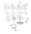
- FIG. 7 schematically illustrates a general purpose computing device 200 of the type that may be used to implement the above described techniques.
- the general purpose computing device 200 includes a central processing unit 202, a random access memory 204 and a read only memory 206, connected together via bus 222.
- the general purpose computing device may be extended to further comprise a network interface card 208, a hard disk drive 210, a display driver 212 and monitor 214 and a user input/output circuit 216 with a keyboard 218 and mouse 220 all connected via the common bus 222.
- the central processing unit 202 will execute computer program instructions that may for example be stored in the random access memory 204 and/or the read only memory 206.
- These core components of the general purpose computing device are labelled 230 in Figure 9.
- the additional components outside the dashed box 230 may additionally be connected, for example when the control system is connected to a diagnostic set-up for pre-programming or for troubleshooting.
- program instructions could be additionally retrieved from the hard disk drive 210 or dynamically downloaded via the network interface card 208.
- the results of the processing performed may be displayed to a user or an engineer via a connected display driver 212 and monitor 214.
- User inputs for controlling the operation of the general purpose computing device 200 may be received via a connected user input output circuit 216 from the keyboard 218 or the mouse 220.
- the computer program could be written in a variety of different computer languages.
- the computer program may be stored locally on a recording medium or dynamically downloaded to the general purpose computing device 200.
- the general purpose computing device 200 can perform the above described techniques and can be considered to form an apparatus for performing the above described technique.
- the architecture of the general purpose computing device 200 could vary considerably and Figure 9 is only one example.
Landscapes
- Engineering & Computer Science (AREA)
- Transportation (AREA)
- Mechanical Engineering (AREA)
- Power Engineering (AREA)
- Life Sciences & Earth Sciences (AREA)
- Sustainable Energy (AREA)
- Sustainable Development (AREA)
- Chemical & Material Sciences (AREA)
- Animal Behavior & Ethology (AREA)
- General Health & Medical Sciences (AREA)
- Public Health (AREA)
- Veterinary Medicine (AREA)
- Health & Medical Sciences (AREA)
- Combustion & Propulsion (AREA)
- Electric Propulsion And Braking For Vehicles (AREA)
- Control Of Multiple Motors (AREA)
Abstract
Description
- The present invention relates to a controller and a control method for a motorised vehicle, and in particular to the control of a motorised vehicle having at least a left wheel and a right wheel, the left wheel being driven by a left motor and the right wheel being driven by a right motor. In accordance with such motorised vehicles, linear motion of the vehicle is typically effected by driving the left motor and the right motor in the same direction, whilst spinning of the vehicle is typically effected by driving the left motor and the right motor in opposite directions. A typical example of such a motorised vehicle is an electric wheelchair.
- Motion of a motorised vehicle such as an electric wheelchair is typically effected by a left and right wheel which can be driven independently. Substantially forward and reverse motion of the vehicle is produced by driving the left and right wheel in the same direction, whilst turning of the vehicle is achieved by driving the left and right wheel at different speeds. Indeed the vehicle may even be caused to spin without substantial linear motion by driving the left and right wheel in opposite directions.
- It is known to drive such left and right wheels of a motorised vehicle by means of a motor, such as an electric motor, connected to each wheel. Control circuitry is typically provided to respond to command signals from a user interface (such as a joystick) and to cause appropriate voltages to be applied to each motor to bring about the motion requested by the user.
- It is further known that the performance of an electric motor, in particular the speed at which it causes an associated wheel to rotate, depends not only on the voltage applied to the motor, but also on the load which is experienced by that motor. When the load increases, for example when the vehicle is climbing a slope, the increased load will cause the motor to turn more slowly for a given supply voltage. In order to counteract such effects, it is known for motorised vehicles such as electric wheelchairs to comprise motor control circuitry which implements a technique known as IR compensation. According to this technique, the motor control circuitry monitors the left and right motor in terms of their instantaneous voltage and current consumption. From these the motor control circuitry can determine the motor speed (primarily determined by the applied armature voltage) and the motor torque (primarily determined by the armature current). The motor control circuitry can then identify situations in which the load on a motor increases (resulting in greater motor torque) by virtue of an increase in the armature current. The real motor speed can be estimated in accordance with the equation:

where kemf is the back e.m.f. constant, Vm is the voltage applied to the motor, Im is the current drawn by the motor and Rm is the resistance of the motor windings (armature). A difference between this real motor speed and the requested motor speed is then calculated and a correction is applied, such that for example when the real motor speed drops due to an increase in load, the motor control circuitry compensates by increasing the voltage supplied to that motor to maintain the requested speed. - However, it has been found that such compensation based feedback mechanisms can make a motorised vehicle such as an electric wheelchair rather unstable when turning. This effect is particularly pronounced when the vehicle is a front wheel drive vehicle, as is often the case for an electric wheelchair. This turn instability for a front wheel drive vehicle results from the fact that the trailing centre of mass of a front wheel drive vehicle (consisting mainly of the weight of the user and the weight of the heavy-duty batteries which power the vehicle) causes the driving torque on the inside wheel to increase, and hence slow down. This has the effect that the radius of turn of the vehicle decreases, without the user having requested such a change in turn radius. The tighter turn radius leads to a higher centripetal force acting on the vehicle (since centripetal force is inversely proportional to turn radius) and this further increases the driving torque on the inside wheel, causing an even tighter turn radius. A true vicious circle thus results, which could have serious consequences for the user of the vehicle.
- It should be noted that this turn instability problem in practice also affects straight line driving. Whilst a user of the vehicle may seek to drive in a straight line, small left or right deviations will always be present (corresponding to a very large turn radius) and any small offset in turning direction (also known as spin demand) will lead to an even tighter turn with positive feedback. The user has to manually compensate and is constantly fighting to keep the vehicle driving straight. The resulting "fish tailing" is an undesirable phenomenon for the user.
- A related problem also arises for front wheel vehicles when driving on a camber. The position of the centre of mass of the vehicle behind the front wheels causes the uphill wheel load to increase, and hence slow down, turning the vehicle up the slope. This effect (known as "camber veer") can be particularly problematic for front wheel drive wheelchairs which implement a "gate shaping algorithm", since this tends to slow the wheelchair down as the spin demand increases, and thus only a small correction window is available to the user seeking to avoid this veering effect.
- Some background technological information to the present invention can be found in the "enAble40 Powerchair Control System" manual produced by Curtis Instruments, Inc. of New York, USA; in
US Patents 5,033,000 and5,307,888 ; and inUS Patent Application Publication 2010/0007299 A1 . - Accordingly it would be desirable to provide an improved technique for controlling such motorised vehicles.
- According to a first aspect, the present invention provides a controller for a motorised vehicle having at least a left wheel and a right wheel, said left wheel being driven by a left motor and said right wheel being driven by a right motor, the controller being arranged to receive control signals from a user input device of the motorised vehicle, the controller comprising: motor monitoring circuitry configured to monitor output signals from said left motor and said right motor respectively, and to detect in dependence on said output signals a loading imbalance between said left motor and said right motor; and motor control circuitry configured on detection of said loading imbalance to apply a slowing correction to a less loaded motor of said left motor and said right motor.
- According to the techniques of the present invention a controller for the motorised vehicle comprises motor monitoring circuitry which monitors output signals from each of the motors, and in dependence on those output signals can detect the occurrence of a loading imbalance between the motors. When such a loading imbalance is detected, the motor control circuitry then applies a slowing correction to the less loaded of the two motors. According to prior art techniques, the detection of one of the motors being more greatly loaded than the other would typically be responded to by increasing the power to that more greatly loaded motor. This is due to the fact that each motor is usually monitored individually and corrections are applied to each motor in dependence on its own loading situation. For example in the case of an electric wheelchair, increased load on one motor would result in a higher voltage being applied to that motor, seeking to match its real speed output to that requested by the user. However, the inventor of the present invention realised that the above described control problems (such as turn instability and camber veer) cannot be fully solved by this known approach, and has found that a significant improvement in the controllability of such motorised vehicles results from providing motor control circuitry configured to monitor both motors and to apply a slowing correction to the less loaded motor, when a loading imbalance is detected.
- There are a number of ways in which the motor control circuitry could determine an appropriate slowing correction, but in one embodiment said control signals determine a demanded turn radius of the motorised vehicle and said motor control circuitry is configured to apply said slowing correction to preserve said demanded turn radius. It will be appreciated that the control signals from the user input device of the motorised vehicle will determine a demanded turn radius which the user wishes the motorised vehicle to take. Of course this demanded turn radius can be extremely large - when the user wishes to travel in a straight line. By determining the slowing correction so as to preserve the demanded turn radius when a loading imbalance between the left and right motor occurs, the controlling characteristics of the motorised vehicle are improved, since the vehicle responds to the user commands in a manner which more accurately reflects the user's wishes.
- There are various ways in which the control signals could be converted into motion of the motorised vehicle, but in embodiments said control signals determine a left motor demand speed and a right motor demand speed, said left motor being controlled in dependence on said left motor demand speed and said right motor being controlled in dependence on said right motor demand speed. Hence by establishing a demand speed for each of the left and right motors respectively, the left and right motors may be simply controlled in dependence on their respective demand speeds.
- In one embodiment, the motor control circuitry is configured to apply said slowing correction by reducing one of said left motor demand speed and said right motor demand speed. Hence, the slowing correction may be applied in response to the detection of the loading imbalance by reducing the demand speed corresponding to the less loaded motor.
- In other embodiments, said controller comprises a left feedback control loop, wherein said left feedback control loop comprises a left motor speed feedback unit configured to generate a feedback left motor speed in dependence on said output signals from said left motor; a right feedback control loop, wherein said right feedback control loop comprises a right motor speed feedback unit configured to generate a feedback right motor speed in dependence on said output signals from said right motor; and said motor control circuitry comprises comparison circuitry for controlling said left motor in dependence on a difference between said left motor demand speed and said feedback left motor speed, and for controlling said right motor in dependence on a difference between said right motor demand speed and said feedback right motor speed.
- Generating a feedback motor speed in each of the left and right motors in dependence on the output signals from those motors provides a feedback mechanism for the motor control circuitry to control each of the left and right motors in a stable manner, controlling each motor in dependence on a difference between the feedback motor speed and the demand speed for that motor. This enables the motor control circuitry to adjust the performance of the left and right motor in dependence on a measurement on their current performance.
- In such embodiments, said motor control circuitry may be configured to apply said slowing correction by increasing one of said feedback left motor speed and said feedback right motor speed. Thus, in order to apply the slowing correction to one of the motors, this may be effected by increasing the feedback motor speed of that motor, such that the comparison circuitry of the motor control circuitry determines that that motor is (from the point of view of the comparison circuitry) currently turning faster than it has been requested to do, and thus reduces the motor speed.
- The output signals from the left motor and the right motor could take a number of forms, but in embodiments said output signals from said left motor and said right motor respectively comprise a left motor current consumption and a right motor current consumption respectively. In a motorised vehicle driven by electric motors, the current consumption of each motor is indicative of the load experienced by that motor, and hence monitoring the current consumption of the left and right motor respectively enables the loading imbalance to be detected.
- In some such embodiments, said left motor speed feedback unit comprises a left IR compensation unit configured to generate said feedback left motor speed in dependence on said left motor current consumption, and said right motor speed feedback unit comprises a right IR compensation unit configured to generate said feedback right motor speed in dependence on said right motor current consumption. An IR compensation unit for each of the left and right motors respectively allows the controller to compensate for the armature resistance in each motor and hence maintain the output speed of each motor at a desired level, even as the load on that motor changes. To avoid the control problem of "positive-feedback", only partial compensation by this method can be made.
- In some embodiments said motor monitoring circuitry further comprises motor speed determination circuitry configured to use full compensation to determine an actual left motor speed and an actual right motor speed in dependence on said output signals from said left motor and said right motor respectively. Determining the actual speed of the left motor and right motor respectively enables the motor monitoring circuitry to allow the motor control circuitry to control each motor in dependence on its determined actual speed and hence a more stable speed performance of each motor may be achieved.
- In some embodiments, the motor control circuitry is configured to determine said slowing correction in dependence on said actual left motor speed and said actual right motor speed. Determining the slowing correction in this manner, namely taking both the actual left motor speed and the actual right motor speed into account, enables the slowing correction to be determined such that the overall motion of the motorised vehicle is taken into account, in particular the turn radius of the motorised vehicle.
- In some embodiments said feedback left motor speed is increased by a factor CL given by the formula:

- VRFeedback are said feedback left motor speed and said feedback right motor speed respectively, and where VLreal and VRreal are said actual left motor speed and said actual right motor speed respectively.
- In some embodiments said feedback right motor speed is increased by a factor CR given by the formula:

- In some such embodiments said motor control circuitry is configured to limit said slowing correction for said left motor to a magnitude of said actual right motor speed and to limit said slowing correction for said right motor to a magnitude of said actual left motor speed. At small values of the actual motor speed of one motor, the slowing correction required for the other motor may become impossibly large and limiting the slowing correction of one motor to the magnitude of the actual motor speed of the other motor avoids this problem.
- In some embodiments, said motor control circuitry is configured to reduce said slowing correction when an actual speed of said motorised vehicle is less than a predetermined speed. It has been found that the techniques of the present invention are particularly applicable at higher speeds of the motorised vehicle and that a more stable driving experience results when the applied slowing correction is reduced at lower overall speeds of the motorised vehicle.
- In some embodiments, said motorised vehicle is a front wheel drive vehicle. In particular the motor control circuitry may then be configured only to apply said slowing correction when said front wheel drive vehicle is moving forwards. As discussed above, the location of the centre of mass of a front wheel drive vehicle behind the driven wheels when that vehicle is driving forwards results in the need for stabilisation which the present invention provides.
- Conversely, in other embodiments, the motorised vehicle is a rear wheel drive vehicle and then the motor control circuitry may be configured only to apply said slowing correction when said rear wheel drive vehicle is moving backwards.
- The loading imbalance may have a number of sources, but in embodiments said loading imbalance arises due to one or more of the following phenomena increasing the loading on one of said left wheel and said right wheel: (a) friction between at least one of said left wheel and said right wheel and a surface on which the motorised vehicle is driving; (b) a required realignment of castor wheels of the motorised vehicle when the motorised vehicle is turning; (c) weight of the user of the motorised vehicle; (d) a slope on which the motorised vehicle is driving; (e) a centripetal force; and (f) climbing or descending an uneven obstacle.
- Embodiments of the present invention comprise a controller for use in a motorised vehicle taking the form of a wheelchair.
- Viewed from a second aspect, the present invention provides a motorised vehicle comprising: at least a left wheel and a right wheel, said left wheel being driven by a left motor and said right wheel being driven by a right motor; a user input device configured to issue control signals for the motorised vehicle; and a controller according to the first aspect for controlling the driving of said left wheel and said right wheel in dependence on said control signals.
- In some embodiments, said motorised vehicle is a wheelchair.
- Viewed from a third aspect, the present invention provides a method of controlling a motorised vehicle having at least a left wheel and a right wheel, said left wheel being driven by a left motor and said right wheel being driven by a right motor, comprising the steps of: receiving control signals from a user input device of the motorised vehicle; monitoring output signals from said left motor and said right motor respectively; detecting in dependence on said output signals a loading imbalance between said left motor and said right motor; and on detection of said loading imbalance applying a slowing correction to a less loaded motor of said left motor and said right motor.
- Viewed from a fourth aspect, the present invention provides a computer program product comprising a computer program which when executed on a computing device causes a motorised vehicle having at least a left wheel and a right wheel, said left wheel being driven by a left motor and said right wheel being driven by a right motor, to be controlled in accordance with the method of the third aspect.
- Viewed from a fifth aspect, the present invention provides a controller for a motorised vehicle having at least a left wheel and a right wheel, said left wheel being driven by a left motor and said right wheel being driven by a right motor, the controller being arranged to receive control signals from a user input device of the motorised vehicle, the controller comprising: motor monitoring means for monitoring output signals from said left motor and said right motor respectively, and for detecting in dependence on said output signals a loading imbalance between said left motor and said right motor; and motor control means for, on detection of said loading imbalance, applying a slowing correction to a less loaded motor of said left motor and said right motor.
- The present invention will be described further, by way of example only, with reference to embodiments thereof as illustrated in the accompanying drawings, in which:
-
Figure 1 schematically illustrates a motorised vehicle according to one embodiment; -
Figure 2 schematically illustrates in more detail the motor control circuitry shown inFigure 1 ; -
Figure 3 illustrates a series of steps taken by the motor control circuitry ofFigure 1 ; -
Figure 4 is a graph showing a simulation of the variation in radius error with joystick angle; -
Figure 5 is a graph showing a simulation of the variation in the applied feedback correction with joystick angle; -
Figure 6 is a graph showing a simulation of the variation in the wheelchair speed measurement with joystick angle; and -
Figure 7 is a schematic representation of a general purpose computing device which may be used in embodiments of the present invention. -
Figure 1 is a block diagram of a motorised vehicle in accordance with one embodiment of the present invention. For the purposes of the following discussion, the example where the motorised vehicle is an electric wheelchair will be used. In the example ofFigure 1 , the electric wheelchair has achassis 10 to which two motor driven wheels are connected, namely aleft wheel 12 and aright wheel 14. Further, a pair ofcastors castors wheels wheels left wheel 12 is driven by themotor 20 and theright wheel 14 is driven by themotor 22. To make the vehicle move forwards or backwards both wheels are driven in the same direction. To make the vehicle turn to the left or right whilst driving, the wheels are driven the same direction but with different speeds. It is also possible to effect an even tighter turning of the wheelchair, by driving the twowheels - Whilst in
Figure 1 the driven wheels are provided at the front of the wheelchair and thecastors wheelchair chassis 10. As shown inFigure 1 , acontrol unit 30 is provided on thewheelchair chassis 10 which is coupled to aninput control module 32 via which a user of the wheelchair can enter drive commands. Whilst thecontrol unit 30 andinput control module 32 are shown here as separate elements, it will be appreciated that in some embodiments these components may be incorporated into a single housing. As also shown inFigure 1 , theinput control module 32 is, in this example, a joystick, which provides an intuitive user-friendly interface. It should noted that a front wheel drive wheelchair such as that illustrated inFigure 1 will typically have its joystick mounted near the front of the wheelchair for the convenience of the user.Joystick 32 is positioned inFigure 1 for schematic clarity alone. - All of the electrical components on the wheelchair receive power from an on-board battery (not illustrated), which is typically a heavy-duty rechargeable battery capable of providing the relatively large currents used to drive the
motors - The
control unit 30 receives control signals from theuser input device 32, on the basis of which it generates motor control signals which determine the operation ofmotors joystick 32 is a proportional joystick which provides thecontrol unit 30 with digital control signals indicating a forward component and a spin component. In addition thecontrol unit 30 is configured such that the spin requested by the user is limited in dependence on the requested speed. - In operation, the
control unit 30 receives the control signals, and the control signals are passed to demandsignal generator 34, which converts the control signals into a left motor demand speed and a right motor demand speed, which are passed to leftmotor control unit 50 and rightmotor control unit 60 respectively. - Left
motor control unit 50 and rightmotor control unit 60 generate the direct control signals for theleft motor 20 andright motor 22 respectively. In the illustrated embodiment, these are in the form of a voltage applied to each motor, a higher voltage causing the motor to turn faster, the speed of the motor also being dependent on the current load that it is experiencing. Leftmotor control unit 50 and rightmotor control unit 60 each form part of a feedback loop, wherein leftmotor control unit 50 receives feedback signals fromleft motor 20 and rightmotor control unit 60 receives feedback signals fromright motor 22. Typically the feedback signals from themotors 
where kemf is the back e.m.f. constant, Vm is the voltage applied to the motor, Im is the current drawn by the motor and Rm is the resistance of the motor windings (also known as the armature resistance). - The value of Rm is programmed to a chosen value and the current drawn by the motor is monitored. As the current varies the voltage applied to motor is varied with the aim of keeping the speed constant whilst the user input is indicating a constant speed should be maintained. This is done by means of a comparator which compares the feedback speed calculated in accordance with the IR compensation formula above with the currently demanded speed (determined by the user controls). It should be noted that in practice the value of Rm used in the IR compensation is typically only a predetermined proportion (e.g. 70%) of the real armature resistance. This enables the feedback loop formed by the motor, the IR compensation and the comparator to operate in a stable regime.
- The
control unit 30 also comprisescorrection control unit 70, which also receives the feedback signals from both motor 20 andmotor 22. A typical embodiment of thecorrection control unit 70 is as part of an embedded processor in the control unit of the wheelchair. Further description of such a processor is given below with reference toFigure 7 . The operation ofcorrection control unit 70 will be described in more detail in below, however first it is useful to consider some mathematics underlying the motion of the wheelchair. - The speed and spin of the wheelchair may be defined in terms of the velocities (VL and VR respectively) of the left and
right motor 
- In terms of these quantities the turn radius of the wheelchair may be defined as:

- Where Laxle is the distance between
drive wheels equation 1 into equation 2, the turn radius of the wheelchair may then be defined as follows:
- It should be understood that in order to calculate the real turn radius of the wheelchair according to Equation 3, the real left and right motor velocities must be used. However the turn radius may also be calculated using the left and right feedback speeds (VLFeedback and VRFeedback respectively) calculated according to the IR compensation formula above for each motor. One may then determine the real turn radius according to these quantities, introducing a correction factor which will cause each motor controller (in particular each comparator) to operate in accordance with the real turn radius of the wheelchair.
- For a correction factor CL, introduced as a correction factor to VLFeedback, and equating these two ways of calculating the real turn radius, we find:

- Rearranging, the "left" correction factor is then given by:

whilst a "right" correction factor CR may be similarly determined as:
- These correction factors are continuously determined by
correction control unit 70, as is now described with reference toFigure 2. Figure 2 schematically illustrates in more detail the control circuitry for theleft motor 20 and theright motor 22. Left and right demand speeds are received fromdemand signal generator 34 and each enters a control loop by means of which each motor is controlled. - In operation,
motor monitoring circuitry 26 monitors the performance ofleft motor 20, whilstmotor monitoring circuitry 28 monitors the performance ofright motor 22. The basic feedback control loop for each motor comprises the respective motor monitoring circuitry performing the above described IR compensation and passing a feedback motor speed which is compared (bycomparators - In accordance with the techniques of the present invention the
correction control unit 70 is introduced, which also receives the left and right feedback motor speeds from themonitor monitoring circuitry motor monitoring circuitry correction control unit 70 with an estimate of the real speed of each motor (VLreal and VRreal respectively). Thecorrection control unit 70 then determines the left and right correction factors CL and CR in accordance with equations 5 and 6 above. Thecorrection control unit 70 can then cause a correction factor to be added to either the left feedback motor speed (VLfeedback) or the right feedback motor speed (VRfeedback). - Firstly, it should be noted that the
correction control unit 70 only applies the correction when both VLreal and VRreal are both positive, i.e. this front wheel drive wheelchair is going forwards.Correction control unit 70 then selects whichever of CL and CR are a positive correction and causes this correction value to be added to the respective feedback path viaadder correction control unit 70 is configured to fade out the corrections CL and CR at lower overall speeds of the wheelchair. It has been found that the techniques of the present invention find the greatest benefit at higher speeds, and can cause some wheelchairs to feel "twitchy" at lower speeds, particularly during acceleration or deceleration. This fading out of the correction is calculated in accordance with equation 7 that follows, which defines a scaling factor for the correction factors in dependence on a predetermined value of Fade Voltage which in this embodiment is set at 10V.
- The operation of the motor control circuitry schematically represented in
Figure 2 is now described in terms of a series of steps as schematically set out inFigure 3 . Whilst the steps are described as a continuous flow, the flow can be considered to begin atstep 115, where themotor monitoring circuitries step 125 it is determined whether both the left and right real motor velocities are positive. If they are not, then the flow proceeds directly to step 170 (described below). - If however both the left and right real motor velocities are positive then the flow proceeds to step 130, where the
correction control unit 70 determines the left and right motor correction values CL and CR. At step 135 it is determined which of these correction values is greater. If the left motor correction value CL is greater then the flow proceeds via the left branch, beginning atstep 140 where the left motor correction value CL is constrained to be a positive value, and less than or equal to the current right real motor velocity. Atstep 145 any appropriate low speed fading factor is applied and atstep 150 the left motor correction value CL is added by means ofadder 84 to the left motor feedback speed value. The flow then proceeds to step 170. Correspondingly, if at step 135 it is determined that the right motor correction value CR is larger, then the flow proceeds via the right branch, beginning atstep 155 where the right motor correction value CR is constrained to be a positive value, and less than or equal to the left real motor velocity. Atstep 160 any low speed fading factor is applied and atstep 165 the right motor correction value CR is added by means ofadder 86 to the right motor feedback value. The flow then proceeds to step 170. - At
step 170, the left and right demand speeds are received from thedemand signal generator 34. Then atstep 175 thecomparators step 180, the left andright motors compensators 72, 74) in dependence on the errors values determined bycomparators step 175. The flow then returns to step 115. - Next
Figures 4 ,5 and6 are discussed which illustrate the results of some simulations carried out for a wheelchair at steady state speed, showing how various quantities are distributed with respect to the joystick angle. InFigure 4 , the "uncorrected" curve illustrates how when the joystick is forward (i.e. between -90° and +90°) a tighter (than demanded) radius of turn results, leading to instability in controlling the chair. The "0.7 corrected" curve shows how the techniques of the present invention can be used to neutralise the negative radius error, and the "0.55 corrected" curve shows how a chosen compensation factor of 0.55 will cause a larger (then demanded) radius of turn, which is naturally stable. -
Figure 5 illustrates a simulation of the left and right correction factors (CL and CR) and clearly demonstrates how the values of these quantities tend to infinity as the opposite motor becomes stationary (see the large spikes at approximately +70° and at approximately -70°). Limiting the correction values to the real speed of the opposite motor, as discussed above, addresses this problem. -
Figure 6 illustrates how the (uncorrected) feedback speed measurement is increased in the forward direction by the techniques of the present invention. Notice that the simulated spikes at ±70° are avoided by limiting the corrected speed measurement with respect to the opposite real motor speed. - In general it has been found that the following improvements were made by introducing techniques of the present invention. Firstly the "fish tailing" effect was reduced. It was found to be much easier to drive in a straight line with the stabilisation algorithm (implementing the techniques of the present invention) switched on. Secondly, "spin-in" on faster turns was reduced. With the stabilisation algorithm switched on it was relatively easy to drive around a four metre diameter circle at full speed. Without the stabilisation algorithm switched on this was difficult, as the wheelchair tended to spiral into a very tight turn. Thirdly, "camber veer" was reduced. When driving across a camber the stabilisation algorithm allowed the wheelchair to continue relatively straight with less tendency to turn up the slope. Furthermore with the stabilisation algorithm switched on, the wheelchair was able to drive faster across a camber, since the usual gate shaping algorithm would normally limit the speed demand as the joystick position was used to manually keep the chair going straight.
-
Figure 7 schematically illustrates a generalpurpose computing device 200 of the type that may be used to implement the above described techniques. As mentioned above, in the context of the present invention this could for example be an embedded processor forming part of the control unit of the wheelchair. The generalpurpose computing device 200 includes acentral processing unit 202, arandom access memory 204 and a read onlymemory 206, connected together viabus 222. More fully, the general purpose computing device may be extended to further comprise anetwork interface card 208, ahard disk drive 210, adisplay driver 212 and monitor 214 and a user input/output circuit 216 with akeyboard 218 andmouse 220 all connected via thecommon bus 222. In operation, such as when forming part of the control system of an active wheelchair, thecentral processing unit 202 will execute computer program instructions that may for example be stored in therandom access memory 204 and/or the read onlymemory 206. These core components of the general purpose computing device are labelled 230 in Figure 9. The additional components outside the dashedbox 230 may additionally be connected, for example when the control system is connected to a diagnostic set-up for pre-programming or for troubleshooting. In such a situation program instructions could be additionally retrieved from thehard disk drive 210 or dynamically downloaded via thenetwork interface card 208. The results of the processing performed may be displayed to a user or an engineer via aconnected display driver 212 and monitor 214. User inputs for controlling the operation of the generalpurpose computing device 200 may be received via a connected userinput output circuit 216 from thekeyboard 218 or themouse 220. It will be appreciated that the computer program could be written in a variety of different computer languages. The computer program may be stored locally on a recording medium or dynamically downloaded to the generalpurpose computing device 200. When operating under control of an appropriate computer program, the generalpurpose computing device 200 can perform the above described techniques and can be considered to form an apparatus for performing the above described technique. The architecture of the generalpurpose computing device 200 could vary considerably and Figure 9 is only one example. - Although a particular embodiment has been described herein, it will be appreciated that the invention is not limited thereto and that many modifications and additions thereto may be made within the scope of the invention. For example, various combinations of the features of the following dependent claims could be made with the features of the independent claims without departing from the scope of the present invention.
- Various further aspects and embodiments are set out in the following numbered clauses.
-
- 1. A controller for a motorised vehicle having at least a left wheel and a right wheel, said left wheel being driven by a left motor and said right wheel being driven by a right motor, the controller being arranged to receive control signals from a user input device of the motorised vehicle, the controller comprising:
- motor monitoring circuitry configured to monitor output signals from said left motor and said right motor respectively, and to detect in dependence on said output signals a loading imbalance between said left motor and said right motor; and
- motor control circuitry configured on detection of said loading imbalance to apply a slowing correction to a less loaded motor of said left motor and said right motor.
- 2. A controller according to
clause 1, wherein said motorised vehicle is a front wheel drive vehicle. - 3. A controller according to clause 2, wherein said motor control circuitry is configured only to apply said slowing correction when said front wheel drive vehicle is moving forwards.
- 4. A controller according to
clause 1, wherein said motorised vehicle is a rear wheel drive vehicle. - 5. A controller according to clause 4, wherein said motor control circuitry is configured only to apply said slowing correction when said rear wheel drive vehicle is moving backwards.
- 6. A controller according to
clause 1, wherein said loading imbalance arises due to one or more of the following phenomena increasing the loading on one of said left wheel and said right wheel:- (a) friction between at least one of said left wheel and said right wheel and a surface on which the motorised vehicle is driving;
- (b) a required realignment of castor wheels of the motorised vehicle when the motorised vehicle is turning;
- (c) weight of the user of the motorised vehicle;
- (d) a slope on which the motorised vehicle is driving;
- (e) a centripetal force; and
- (f) climbing or descending an uneven obstacle.
- 7. A controller according to
clause 1, for use in a motorised vehicle taking the form of a wheelchair. - 8. A motorised vehicle comprising:
- at least a left wheel and a right wheel, said left wheel being driven by a left motor and said right wheel being driven by a right motor;
- a user input device configured to issue control signals for the motorised vehicle; and
- a controller according to
clause 1 for controlling the driving of said left wheel and said right wheel in dependence on said control signals.
- 9. A motorised vehicle according to clause 8, wherein said motorised vehicle is a wheelchair.
Claims (15)
- A controller for a motorised vehicle having at least a left wheel and a right wheel, said left wheel being driven by a left motor and said right wheel being driven by a right motor, the controller being arranged to receive control signals from a user input device of the motorised vehicle, the controller comprising:motor monitoring circuitry configured to monitor output signals from said left motor and said right motor respectively, and to detect in dependence on said output signals a loading imbalance between said left motor and said right motor; andmotor control circuitry configured on detection of said loading imbalance to apply a slowing correction to a less loaded motor of said left motor and said right motor.
- A controller as claimed in claim 1, wherein said control signals determine a demanded turn radius of the motorised vehicle and said motor control circuitry is configured to apply said slowing correction to preserve said demanded turn radius.
- A controller as claimed in claim 1 or claim 2, wherein said control signals determine a left motor demand speed and a right motor demand speed, said left motor being controlled in dependence on said left motor demand speed and said right motor being controlled in dependence on said right motor demand speed.
- A controller as claimed in claim 3, wherein said motor control circuitry is configured to apply said slowing correction by reducing one of said left motor demand speed and said right motor demand speed.
- A controller as claimed in claim 3, wherein said controller comprises:a left feedback control loop, wherein said left feedback control loop comprises a left motor speed feedback unit configured to generate a feedback left motor speed in dependence on said output signals from said left motor;a right feedback control loop, wherein said right feedback control loop comprises a right motor speed feedback unit configured to generate a feedback right motor speed in dependence on said output signals from said right motor; andsaid motor control circuitry comprises comparison circuitry for controlling said left motor in dependence on a difference between said left motor demand speed and said feedback left motor speed, and for controlling said right motor in dependence on a difference between said right motor demand speed and said feedback right motor speed.
- A controller as claimed in claim 5, wherein said motor control circuitry is configured to apply said slowing correction by increasing one of said feedback left motor speed and said feedback right motor speed.
- A controller as claimed in claim 5 or claim 6, wherein said output signals from said left motor and said right motor respectively comprise a left motor current consumption and a right motor current consumption respectively.
- A controller as claimed in claim 7, wherein said left motor speed feedback unit comprises a left IR compensation unit configured to generate said feedback left motor speed in dependence on said left motor current consumption, and said right motor speed feedback unit comprises a right IR compensation unit configured to generate said feedback right motor speed in dependence on said right motor current consumption.
- A controller as claimed in any preceding claim, wherein said motor monitoring circuitry further comprises motor speed determination circuitry configured to use full compensation to determine an actual left motor speed and an actual right motor speed in dependence on said output signals from said left motor and said right motor respectively.
- A controller as claimed in claim 9, wherein said motor control circuitry is configured to determine said slowing correction in dependence on said actual left motor speed and said actual right motor speed, wherein an increase in said feedback left motor speed is determined by a factor CL given by the formula:

left motor speed and said feedback right motor speed respectively, and where VLreal and VRreal are said actual left motor speed and said actual right motor speed respectively, and wherein an increase in said feedback right motor speed is determined by a factor CR given by the formula:
- A controller as claimed in claim 10, wherein said motor control circuitry is configured to limit said slowing correction for said left motor to a magnitude of said actual right motor speed and to limit said slowing correction for said right motor to a magnitude of said actual left motor speed.
- A controller as claimed in any preceding claim, wherein said motor control circuitry is configured to reduce said slowing correction when an actual speed of said motorised vehicle is less than a predetermined speed.
- A motorised vehicle comprising:at least a left wheel and a right wheel, said left wheel being driven by a left motor and said right wheel being driven by a right motor;a user input device configured to issue control signals for the motorised vehicle; anda controller as claimed in any preceding claim for controlling the driving of said left wheel and said right wheel in dependence on said control signals.
- A method of controlling a motorised vehicle having at least a left wheel and a right wheel, said left wheel being driven by a left motor and said right wheel being driven by a right motor, comprising the steps of:receiving control signals from a user input device of the motorised vehicle;monitoring output signals from said left motor and said right motor respectively;detecting in dependence on said output signals a loading imbalance between said left motor and said right motor; andon detection of said loading imbalance applying a slowing correction to a less loaded motor of said left motor and said right motor.
- A computer program product comprising a computer program which when executed on a computing device causes a motorised vehicle having at least a left wheel and a right wheel, said left wheel being driven by a left motor and said right wheel being driven by a right motor, to be controlled in accordance with the method of claim 14.
Applications Claiming Priority (1)
| Application Number | Priority Date | Filing Date | Title |
|---|---|---|---|
| GB201004985A GB2478957B (en) | 2010-03-24 | 2010-03-24 | A controller and control method for a motorised vehicle |
Publications (2)
| Publication Number | Publication Date |
|---|---|
| EP2368746A2 true EP2368746A2 (en) | 2011-09-28 |
| EP2368746A3 EP2368746A3 (en) | 2017-12-13 |
Family
ID=42228298
Family Applications (1)
| Application Number | Title | Priority Date | Filing Date |
|---|---|---|---|
| EP11158619.4A Withdrawn EP2368746A3 (en) | 2010-03-24 | 2011-03-17 | A controller and control method for a motorised vehicle |
Country Status (4)
| Country | Link |
|---|---|
| US (1) | US9016410B2 (en) |
| EP (1) | EP2368746A3 (en) |
| CN (1) | CN102201765B (en) |
| GB (1) | GB2478957B (en) |
Cited By (4)
| Publication number | Priority date | Publication date | Assignee | Title |
|---|---|---|---|---|
| EP3017798A4 (en) * | 2013-07-04 | 2016-08-10 | Yamaha Motor Co Ltd | ELECTRICALLY POWERED DEVICE FOR WHEELCHAIRS, ELECTRICAL WHEELCHAIR COMPRISING SAID ELECTRICALLY POWERED DEVICE FOR WHEELCHAIRS, AND DRIVING MONITORING METHOD FOR ELECTRIC WHEELCHAIRS |
| WO2020143978A1 (en) * | 2019-01-08 | 2020-07-16 | Bayerische Motoren Werke Aktiengesellschaft | Device for calibrating two electric motors mounted on one axle in two-axle motor vehicles |
| US10864127B1 (en) | 2017-05-09 | 2020-12-15 | Pride Mobility Products Corporation | System and method for correcting steering of a vehicle |
| WO2023223227A1 (en) * | 2022-05-17 | 2023-11-23 | Bsl Ch Ag | Vehicle torque control mechanism |
Families Citing this family (21)
| Publication number | Priority date | Publication date | Assignee | Title |
|---|---|---|---|---|
| US9027681B2 (en) | 2009-12-04 | 2015-05-12 | Massachusetts Institute Of Technology | Hybrid sensor-enabled electric wheel and associated systems, multi-hub wheel spoking systems, and methods of manufacturing and installing wheel spokes |
| US10308065B2 (en) | 2014-04-04 | 2019-06-04 | Superpedestrian, Inc. | Devices and methods for connecting a spoke to a hub |
| EP3126184B1 (en) | 2014-04-04 | 2019-09-04 | Superpedestrian, Inc. | Systems, methods, and devices for the operation of electrically motorized vehicles |
| US10005317B2 (en) | 2014-04-04 | 2018-06-26 | Superpedestrian, Inc. | Devices and methods of thermal management for a motorized wheel |
| US9638502B1 (en) * | 2014-08-18 | 2017-05-02 | Rockwell Collins, Inc. | Pulse error correction for spinning vehicles |
| CN107206907B (en) | 2014-11-24 | 2020-02-14 | 极步公司 | Apparatus and method for a motor vehicle wheel |
| CN104760594B (en) * | 2015-02-28 | 2017-01-25 | 吉林大学 | Wheel torque distribution method for achieving lowest instant energy consumption |
| US10926756B2 (en) | 2016-02-23 | 2021-02-23 | Deka Products Limited Partnership | Mobility device |
| US10908045B2 (en) | 2016-02-23 | 2021-02-02 | Deka Products Limited Partnership | Mobility device |
| US11399995B2 (en) | 2016-02-23 | 2022-08-02 | Deka Products Limited Partnership | Mobility device |
| CA3278463A1 (en) | 2016-02-23 | 2025-10-27 | Deka Products Limited Partnership | Mobility device control system |
| EP3443426B1 (en) | 2016-04-14 | 2022-10-26 | DEKA Products Limited Partnership | A transporter and a control method for a transporter |
| JP6328721B2 (en) * | 2016-10-12 | 2018-05-23 | Ntn株式会社 | Drive source control device and vehicle equipped with the drive source control device |
| DE102016221367B4 (en) * | 2016-10-28 | 2022-05-19 | Ford Global Technologies, Llc | Method for propulsion control of a three-lane vehicle and vehicle |
| USD829612S1 (en) | 2017-05-20 | 2018-10-02 | Deka Products Limited Partnership | Set of toggles |
| USD846452S1 (en) | 2017-05-20 | 2019-04-23 | Deka Products Limited Partnership | Display housing |
| USD1047785S1 (en) | 2017-05-20 | 2024-10-22 | Deka Products Limited Partnership | Toggle control device |
| JP2021527204A (en) | 2018-06-07 | 2021-10-11 | デカ・プロダクツ・リミテッド・パートナーシップ | Systems and methods for delivery multipurpose service execution |
| US11730645B1 (en) * | 2019-04-26 | 2023-08-22 | Patroness, LLC | Systems and methods to upgrade a motorized mobile chair to a smart motorized mobile chair |
| CN111240266B (en) * | 2020-01-16 | 2021-08-10 | 湖南格兰博智能科技有限责任公司 | Two-wheel speed irregularity optimization algorithm applied to sweeping robot |
| WO2023141833A1 (en) * | 2022-01-26 | 2023-08-03 | 浙江益恒悦医疗科技有限公司 | Power-assisted steering control method and power-assisted steering control device of walking aid, and memory |
Citations (3)
| Publication number | Priority date | Publication date | Assignee | Title |
|---|---|---|---|---|
| US5033000A (en) | 1988-06-09 | 1991-07-16 | Natco Corporation | Variable keyed power distribution and control system for motorized wheelchair |
| US5307888A (en) | 1991-09-12 | 1994-05-03 | Giat Industries | Method and apparatus for controlling the steering of a vehicle that is tracked or that has non-steerable wheels |
| US20100007299A1 (en) | 2008-07-11 | 2010-01-14 | Curtis Instruments, Inc. | Systems and methods for dynamically compensating motor resistance in electric motors |
Family Cites Families (32)
| Publication number | Priority date | Publication date | Assignee | Title |
|---|---|---|---|---|
| US3133237A (en) * | 1962-04-11 | 1964-05-12 | Gen Electric | Rotary converter fed motor control for a vehicle |
| US3597674A (en) * | 1969-06-11 | 1971-08-03 | Abbey Harold | Solid-state regulation of power supplies |
| US3787723A (en) * | 1970-03-02 | 1974-01-22 | Deere & Co | Vehicular drive system with electric assist |
| DE2139571A1 (en) * | 1971-08-06 | 1973-02-15 | Linde Ag | VEHICLE DRIVE WITH TWO ELECTRIC MOTORS |
| AU541284B2 (en) * | 1978-07-28 | 1985-01-03 | Bio-Med Pty. Ltd. | Control arrangement for electric motors |
| JPS63262002A (en) * | 1987-04-17 | 1988-10-28 | Fuji Electric Co Ltd | Detection of wheel slip of electric vehicle |
| JP2752539B2 (en) * | 1991-09-21 | 1998-05-18 | 株式会社日立製作所 | Control device for vehicle electric motor |
| JPH07203606A (en) * | 1994-01-05 | 1995-08-04 | Meidensha Corp | Controlling device of torque of electric vehicle |
| US5487437A (en) * | 1994-03-07 | 1996-01-30 | Avitan; Isaac | Coupled differential turning control system for electric vehicle traction motors |
| JPH0920223A (en) * | 1995-07-07 | 1997-01-21 | Nippondenso Co Ltd | Road condition identification device |
| CA2270184C (en) * | 1996-10-11 | 2005-05-17 | Wheelchair Carrier, Inc. | Lightweight motorized wheelchair |
| US5939846A (en) * | 1997-09-04 | 1999-08-17 | General Electric Company | AC motorized wheel control system |
| US6615937B2 (en) * | 1999-07-30 | 2003-09-09 | Invacare Corporation | Motorized wheelchairs |
| US6154690A (en) * | 1999-10-08 | 2000-11-28 | Coleman; Raquel | Multi-feature automated wheelchair |
| JP2001327544A (en) * | 2000-03-15 | 2001-11-27 | Fuji Heavy Ind Ltd | Wheelchair auxiliary power unit |
| US6734647B2 (en) * | 2001-10-30 | 2004-05-11 | Honda Giken Kogyo Kabushiki Kaisha | Working machine |
| JP4062085B2 (en) * | 2002-12-18 | 2008-03-19 | 株式会社豊田自動織機 | Electric industrial vehicle steering system |
| NL1023836C2 (en) * | 2003-07-07 | 2005-01-10 | Indes Holding Bv | Wheelchair and operating means for use in such a wheelchair. |
| US7159181B2 (en) * | 2003-10-01 | 2007-01-02 | Sunrise Medical Hhg Inc. | Control system with customizable menu structure for personal mobility vehicle |
| CN1746064A (en) * | 2004-09-09 | 2006-03-15 | 比亚迪股份有限公司 | Electric vehicle steering system and electric vehicle steering method |
| JP2006109547A (en) * | 2004-09-30 | 2006-04-20 | Sanyo Electric Co Ltd | Electric vehicle and electric vehicle driving control program |
| US7403844B2 (en) * | 2005-08-31 | 2008-07-22 | Invacare Corporation | Method and apparatus for programming parameters of a power driven wheelchair for a plurality of drive settings |
| WO2007044913A2 (en) * | 2005-10-11 | 2007-04-19 | Sunrise Medical Hhg Inc. | Wheelchair with motor speed and torque control |
| ES2781771T3 (en) * | 2005-11-29 | 2020-09-07 | Denso Corp | Control apparatus and method for electric vehicles |
| IL174061A0 (en) * | 2006-03-02 | 2006-08-01 | Amihud Rabin | Safety control system for electric vehicle |
| JP4755063B2 (en) * | 2006-10-26 | 2011-08-24 | 三菱重工業株式会社 | Electric vehicle, its slip control device and control method |
| GB2444963B (en) * | 2006-11-30 | 2010-03-10 | P G Drives Technology Ltd | A control system for controlling a motor arrangement for differentially driving left and right wheels of a motorized vehicle |
| EP1972314B1 (en) * | 2006-12-25 | 2009-06-03 | Kwang Yang Motor Co., Ltd. | Direction and speed control device for an electronic wheelchair |
| EP1972486A1 (en) * | 2007-03-19 | 2008-09-24 | Invacare International Sàrl | Motorized wheelchair |
| US8315770B2 (en) * | 2007-11-19 | 2012-11-20 | Invacare Corporation | Motorized wheelchair |
| JP2009225537A (en) * | 2008-03-14 | 2009-10-01 | Autech Japan Inc | Driving force control device |
| CN101574979B (en) * | 2009-06-11 | 2012-01-25 | 重庆大学 | Electric motor car differential steeling control method based on slip rate control |
-
2010
- 2010-03-24 GB GB201004985A patent/GB2478957B/en not_active Expired - Fee Related
- 2010-05-14 US US12/780,748 patent/US9016410B2/en not_active Expired - Fee Related
-
2011
- 2011-03-17 EP EP11158619.4A patent/EP2368746A3/en not_active Withdrawn
- 2011-03-24 CN CN201110071890.1A patent/CN102201765B/en not_active Expired - Fee Related
Patent Citations (3)
| Publication number | Priority date | Publication date | Assignee | Title |
|---|---|---|---|---|
| US5033000A (en) | 1988-06-09 | 1991-07-16 | Natco Corporation | Variable keyed power distribution and control system for motorized wheelchair |
| US5307888A (en) | 1991-09-12 | 1994-05-03 | Giat Industries | Method and apparatus for controlling the steering of a vehicle that is tracked or that has non-steerable wheels |
| US20100007299A1 (en) | 2008-07-11 | 2010-01-14 | Curtis Instruments, Inc. | Systems and methods for dynamically compensating motor resistance in electric motors |
Cited By (6)
| Publication number | Priority date | Publication date | Assignee | Title |
|---|---|---|---|---|
| EP3017798A4 (en) * | 2013-07-04 | 2016-08-10 | Yamaha Motor Co Ltd | ELECTRICALLY POWERED DEVICE FOR WHEELCHAIRS, ELECTRICAL WHEELCHAIR COMPRISING SAID ELECTRICALLY POWERED DEVICE FOR WHEELCHAIRS, AND DRIVING MONITORING METHOD FOR ELECTRIC WHEELCHAIRS |
| US9731784B2 (en) | 2013-07-04 | 2017-08-15 | Yamaha Hatsudoki Kabushiki Kaisha | Wheelchair electric device, electric wheelchair with wheelchair electric device and drive monitoring method for electric wheelchair |
| US10864127B1 (en) | 2017-05-09 | 2020-12-15 | Pride Mobility Products Corporation | System and method for correcting steering of a vehicle |
| WO2020143978A1 (en) * | 2019-01-08 | 2020-07-16 | Bayerische Motoren Werke Aktiengesellschaft | Device for calibrating two electric motors mounted on one axle in two-axle motor vehicles |
| US11850949B2 (en) | 2019-01-08 | 2023-12-26 | Bayerische Motoren Werke Aktiengesellschaft | Device for calibrating two electric motors mounted on one axle in two-axle motor vehicles |
| WO2023223227A1 (en) * | 2022-05-17 | 2023-11-23 | Bsl Ch Ag | Vehicle torque control mechanism |
Also Published As
| Publication number | Publication date |
|---|---|
| GB2478957B (en) | 2014-07-09 |
| GB201004985D0 (en) | 2010-05-12 |
| US20110232977A1 (en) | 2011-09-29 |
| EP2368746A3 (en) | 2017-12-13 |
| CN102201765A (en) | 2011-09-28 |
| US9016410B2 (en) | 2015-04-28 |
| GB2478957A (en) | 2011-09-28 |
| CN102201765B (en) | 2015-11-04 |
Similar Documents
| Publication | Publication Date | Title |
|---|---|---|
| US9016410B2 (en) | Controller and control method for a motorised vehicle | |
| AU2010200598B2 (en) | Turning motion assistance device for electric vehicle | |
| JP6022946B2 (en) | Apparatus and method for controlling a vehicle | |
| US8958976B2 (en) | Traveling apparatus, control method therefor, and control program | |
| EP2112053B1 (en) | Yaw stability control system | |
| EP2368747A2 (en) | A controller and control method for a motorised vehicle | |
| US20230021908A1 (en) | Systems and methods for controlling speed differential of wheels of a vehicle | |
| CN109532843A (en) | Controller of vehicle | |
| CN107848526A (en) | Turn inside diameter control device | |
| CN118618015B (en) | A fault-tolerant control method for distributed drive vehicles under wheel hub motor demagnetization fault | |
| JP2005297622A (en) | Steering system | |
| US8731754B2 (en) | Controller and control method for a motorised vehicle | |
| US20200039504A1 (en) | Method and Apparatus for Controlling a Vehicle | |
| KR20240033823A (en) | Method for controlling driving of vehicle | |
| CN113022600B (en) | Shuttle vehicle differential control method and device based on current and vehicle | |
| JP2013112108A (en) | Inverted moving body, control method thereof and program | |
| JP2007008242A (en) | Vehicle steering control device and vehicle steering control method | |
| JP2019068680A (en) | Power control apparatus | |
| JP2670626B2 (en) | Vehicle attitude control device | |
| CN120863638B (en) | Vehicle over-bending control method, device and equipment based on angle module and storage medium | |
| CN114013499B (en) | Transverse control system and method for unmanned formula racing car and vehicle | |
| CN117698446A (en) | Load current monitoring control method and system for six-wheel drive chassis | |
| JP2021151806A (en) | Steering controller and steering system | |
| WO2016075811A1 (en) | Turning assistance system for electric vehicle, electric vehicle, and rotary electrical machine | |
| HK1179583B (en) | Apparatus and methods for control of a vehicle |
Legal Events
| Date | Code | Title | Description |
|---|---|---|---|
| PUAI | Public reference made under article 153(3) epc to a published international application that has entered the european phase |
Free format text: ORIGINAL CODE: 0009012 |
|
| AK | Designated contracting states |
Kind code of ref document: A2 Designated state(s): AL AT BE BG CH CY CZ DE DK EE ES FI FR GB GR HR HU IE IS IT LI LT LU LV MC MK MT NL NO PL PT RO RS SE SI SK SM TR |
|
| AX | Request for extension of the european patent |
Extension state: BA ME |
|
| RAP1 | Party data changed (applicant data changed or rights of an application transferred) |
Owner name: PENNY & GILES CONTROLS LIMITED |
|
| PUAL | Search report despatched |
Free format text: ORIGINAL CODE: 0009013 |
|
| AK | Designated contracting states |
Kind code of ref document: A3 Designated state(s): AL AT BE BG CH CY CZ DE DK EE ES FI FR GB GR HR HU IE IS IT LI LT LU LV MC MK MT NL NO PL PT RO RS SE SI SK SM TR |
|
| AX | Request for extension of the european patent |
Extension state: BA ME |
|
| RIC1 | Information provided on ipc code assigned before grant |
Ipc: B60L 3/10 20060101AFI20171107BHEP Ipc: B60L 15/20 20060101ALI20171107BHEP Ipc: A61G 5/04 20130101ALI20171107BHEP |
|
| STAA | Information on the status of an ep patent application or granted ep patent |
Free format text: STATUS: THE APPLICATION HAS BEEN PUBLISHED |
|
| STAA | Information on the status of an ep patent application or granted ep patent |
Free format text: STATUS: THE APPLICATION IS DEEMED TO BE WITHDRAWN |
|
| 18D | Application deemed to be withdrawn |
Effective date: 20180614 |