EP2368660A1 - Method of controlling machine tool and machine tool - Google Patents
Method of controlling machine tool and machine tool Download PDFInfo
- Publication number
- EP2368660A1 EP2368660A1 EP09831796A EP09831796A EP2368660A1 EP 2368660 A1 EP2368660 A1 EP 2368660A1 EP 09831796 A EP09831796 A EP 09831796A EP 09831796 A EP09831796 A EP 09831796A EP 2368660 A1 EP2368660 A1 EP 2368660A1
- Authority
- EP
- European Patent Office
- Prior art keywords
- cutter
- workpiece
- relieving
- machine tool
- machining
- Prior art date
- Legal status (The legal status is an assumption and is not a legal conclusion. Google has not performed a legal analysis and makes no representation as to the accuracy of the status listed.)
- Withdrawn
Links
- 238000000034 method Methods 0.000 title claims abstract description 40
- 238000003754 machining Methods 0.000 claims abstract description 70
- 238000007796 conventional method Methods 0.000 description 3
- 230000001360 synchronised effect Effects 0.000 description 3
- 238000013459 approach Methods 0.000 description 2
- 230000000630 rising effect Effects 0.000 description 2
- 230000000694 effects Effects 0.000 description 1
- 238000007493 shaping process Methods 0.000 description 1
- 230000003068 static effect Effects 0.000 description 1
Images




Classifications
-
- B—PERFORMING OPERATIONS; TRANSPORTING
- B23—MACHINE TOOLS; METAL-WORKING NOT OTHERWISE PROVIDED FOR
- B23F—MAKING GEARS OR TOOTHED RACKS
- B23F23/00—Accessories or equipment combined with or arranged in, or specially designed to form part of, gear-cutting machines
- B23F23/006—Equipment for synchronising movement of cutting tool and workpiece, the cutting tool and workpiece not being mechanically coupled
-
- B—PERFORMING OPERATIONS; TRANSPORTING
- B23—MACHINE TOOLS; METAL-WORKING NOT OTHERWISE PROVIDED FOR
- B23F—MAKING GEARS OR TOOTHED RACKS
- B23F5/00—Making straight gear teeth involving moving a tool relatively to a workpiece with a rolling-off or an enveloping motion with respect to the gear teeth to be made
- B23F5/12—Making straight gear teeth involving moving a tool relatively to a workpiece with a rolling-off or an enveloping motion with respect to the gear teeth to be made by planing or slotting
- B23F5/16—Making straight gear teeth involving moving a tool relatively to a workpiece with a rolling-off or an enveloping motion with respect to the gear teeth to be made by planing or slotting the tool having a shape similar to that of a spur wheel or part thereof
-
- Y—GENERAL TAGGING OF NEW TECHNOLOGICAL DEVELOPMENTS; GENERAL TAGGING OF CROSS-SECTIONAL TECHNOLOGIES SPANNING OVER SEVERAL SECTIONS OF THE IPC; TECHNICAL SUBJECTS COVERED BY FORMER USPC CROSS-REFERENCE ART COLLECTIONS [XRACs] AND DIGESTS
- Y10—TECHNICAL SUBJECTS COVERED BY FORMER USPC
- Y10T—TECHNICAL SUBJECTS COVERED BY FORMER US CLASSIFICATION
- Y10T409/00—Gear cutting, milling, or planing
- Y10T409/10—Gear cutting
- Y10T409/101431—Gear tooth shape generating
- Y10T409/103816—Milling with radial faced tool
- Y10T409/103975—Process
-
- Y—GENERAL TAGGING OF NEW TECHNOLOGICAL DEVELOPMENTS; GENERAL TAGGING OF CROSS-SECTIONAL TECHNOLOGIES SPANNING OVER SEVERAL SECTIONS OF THE IPC; TECHNICAL SUBJECTS COVERED BY FORMER USPC CROSS-REFERENCE ART COLLECTIONS [XRACs] AND DIGESTS
- Y10—TECHNICAL SUBJECTS COVERED BY FORMER USPC
- Y10T—TECHNICAL SUBJECTS COVERED BY FORMER US CLASSIFICATION
- Y10T409/00—Gear cutting, milling, or planing
- Y10T409/10—Gear cutting
- Y10T409/101431—Gear tooth shape generating
- Y10T409/10477—Gear tooth shape generating by relative axial movement between synchronously indexing or rotating work and cutter
- Y10T409/105088—Displacing cutter axially relative to work [e.g., gear shaving, etc.]
-
- Y—GENERAL TAGGING OF NEW TECHNOLOGICAL DEVELOPMENTS; GENERAL TAGGING OF CROSS-SECTIONAL TECHNOLOGIES SPANNING OVER SEVERAL SECTIONS OF THE IPC; TECHNICAL SUBJECTS COVERED BY FORMER USPC CROSS-REFERENCE ART COLLECTIONS [XRACs] AND DIGESTS
- Y10—TECHNICAL SUBJECTS COVERED BY FORMER USPC
- Y10T—TECHNICAL SUBJECTS COVERED BY FORMER US CLASSIFICATION
- Y10T409/00—Gear cutting, milling, or planing
- Y10T409/10—Gear cutting
- Y10T409/101431—Gear tooth shape generating
- Y10T409/10477—Gear tooth shape generating by relative axial movement between synchronously indexing or rotating work and cutter
- Y10T409/105088—Displacing cutter axially relative to work [e.g., gear shaving, etc.]
- Y10T409/105247—Using gear shaper-cutter
Definitions
- the present invention relates to a method of controlling a machine tool and a machine tool.
- a gear shaper is a machine tool including a cutter reciprocating mechanism in which a working tool (hereinafter called cutter) is reciprocated in a center axis direction of an object to be machined (hereinafter called a workpiece.) so as to machine the workpiece in its advancing path and to be moved away from the workpiece in its returning path.
- a working tool hereinafter called cutter
- a workpiece an object to be machined
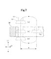
- Fig. 7 is a schematic view showing how a workpiece is machined in a conventional gear shaper.
- the gear shaper as disclosed in Patent Document 1 below performs gear cutting by shaping a workpiece 50 in such a manner that a cutter 13 attached to a main spindle 12 is given a rotational movement together with the workpiece 50 while being reciprocated vertically (arrow L1 in Fig. 7 ), the workpiece 50 being placed on a table (not shown) on which the workpiece 50 is attached for the machining.
- the cutter 13 is in a vertical state near its rising end ([a] in Fig. 7 ).
- the cutter 13 is moved straight downward in this state and machines the workpiece 50 during the downward movement ([a] to [c] in Fig. 7 ).
- the cutter 13 is moved away (relieved) R from the workpiece 50 in the arrow L2 direction by the amount of retraction (the amount of relieving) to become in a returning state ([d] in Fig. 7 ).
- the cutter 13 is moved upward in the state of [d]. Near its rising end, the cutter 13 approaches the workpiece 50 by the amount of relieving to become in the vertical state ( [a] in Fig. 7 ). Then, the cutter 13 is moved downward again. By repeating these operations, the cutter 13 machines the workpiece 50 while being reciprocated vertically.
- Fig. 8 is a schematic view showing the relieving direction of the cutter in relieving.
- cutting blades 13a are formed in a side surface of the cutter 13.
- the tip of each cutting blade 13a is located on an addendum circle 13b, and the root of each cutting blade 13a is located on a dedendum circle 13c.
- Fig. 9 is a schematic view showing how an internal gear is formed by the cutter.
- teeth 50a are formed in an inner surface of the workpiece 50 by the cutter 13.
- a portion indicated by a broken line in the workpiece 50 is a portion 50d to be chipped.
- each formed tooth 50a is located on an addendum circle 50b, and the root of each tooth 50a is located on a dedendum circle 50c.
- the cutter 13 is relieved R in a direction connecting the center O 2 of the cutter 13 and the center O 1 of the workpiece 50.
- a direction from the center O 2 of the cutter 13 toward the center O 1 of the workpiece 50 is a relieving direction Rd.
- the cutter 13 and the workpiece 50 during machining sometimes interfere with each other (hereinafter called relieving interference) in the relieving R of the cutter 13, depending on the specifications of the workpiece to be machined into an internal gear, the specifications of the cutter, machining conditions, and the like.
- Fig. 10 is a schematic view showing how the relieving interference occurs.
- the workpiece 50 during machining includes a portion 50e chipped this time and a portion 50f chipped in a previous rotation of the workpiece 50.
- the cutter 13 in the relieving R as shown by a dashed-two dotted line in Fig. 10 sometimes interferes with the portion 50f chipped in the previous rotation of the workpiece 50.
- the relieving interference portion I is briefly illustrated for the sake of understanding; however, the relieving interference actually occurs at multiple positions in an extremely small area between the cutter 13 and the workpiece 50 in Fig. 10 due to machining conditions such as the amount of cut, a cutting speed, and a feed speed. Moreover, if a rotation direction C2 of the cutter 13 and a rotation direction C1 of the workpiece 50 during machining are as shown in the drawing, the interference does not occur in a lower half of the drawing but occurs in an upper half thereof.
- the relieving direction Rd shown in Fig. 10 needs to be changed to a direction of target relieving Rt with which the interference between the workpiece 50 and the cutter 13 shown in Fig. 10 can be prevented.
- a method of causing a static offset in a relative position between the cutter 13 and the workpiece 50 in a direction indicated by Y in Fig. 10 is known as a method of changing the relieving direction Rd to the direction of the target relieving Rt.
- Fig. 11 is a schematic view showing a conventional method of changing the relieving direction Rd to the direction of the target relieving Rt.
- the center O 2 of the cutter 13 and the center O 1 of the workpiece 50 are shifted in the Y direction in Fig. 10 while the relieving direction Rd shown in Part (a) of Fig. 11 is kept as it is.
- This causes the virtual center line of the machine tool originally directed in the relieving direction Rd to be directed in an O 2 O 1 vector, and thus causes the relieving direction Rd to incline relative to the virtual center line.
- the relieving direction Rd can be changed to the direction of the target relieving Rt.
- an object of the present invention is to provide a method of controlling a machine tool and a machine tool which allow preventing relieving interference without using a mechanism for causing an offset between a cutter and a workpiece.
- the machine tool is configured to machine a workpiece to be machined by repeating the steps of: machining the workpiece by moving a cutter for machining the workpiece in a direction parallel to a rotational axis of the cutter while rotating the workpiece together with the cutter; and returning the cutter to a machining start position again after termination of the machining step, the method characterized in that upon the termination of the machining step, offset control is performed such that the cutter is moved away from the workpiece in a rotation direction of the cutter without change in a relative position of the rotational axis of the cutter with respect to the workpiece.
- a method of controlling a machine tool according to a second invention to solve the above problems is the method of controlling a machine tool according to the first invention, characterized in that upon the termination of the machining step, relieving is performed such that the cutter and the workpiece become away from each other by changing relative positions of the rotational axis of the cutter and a rotational axis of the workpiece with respect to each other, and, together with the relieving, the amount by which the cutter is moved away from the workpiece in the rotation direction thereof by the offset control is adjusted, thereby controlling a direction of target relieving.
- a method of controlling a machine tool according to a third invention to solve the above problems is the method of controlling a machine tool according to the first invention, characterized in that upon the termination of the machining step, relieving is performed such that the cutter is moved away from the workpiece, the amount of the relieving is adjusted, and the amount by which the cutter is moved away from the workpiece in the rotation direction thereof by the offset control is adjusted, thereby controlling a direction and magnitude of target relieving.
- a machine tool according to a fourth invention to solve the above problems is a machine tool comprising:
- a machine tool according to a fifth invention to solve the above problems is the machine tool according to the fourth invention, characterized in that the control means performs control such that relieving is performed in which the cutter is moved away from the workpiece upon the termination of the machining step, and adjusts the amount by which the cutter is moved away from the workpiece in the rotation direction thereof by the offset control together with the relieving, thereby controlling a direction of target relieving.
- a machine tool according to a sixth invention to solve the above problems is the machine tool according to the fourth invention, characterized in that the control means performs control such that relieving is performed in which the cutter is moved away from the workpiece upon the termination of the machining step, and adjusts the amount of the relieving and the amount by which the cutter is moved away from the workpiece in the rotation direction thereof by the offset control, thereby controlling a direction and magnitude of target relieving.
- the present invention can provide a method of controlling a machine tool and a machine tool which allow preventing relieving interference without using a mechanism for causing an offset between a cutter and a workpiece.
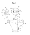
- Fig. 4 is a schematic view showing principal portions of the machine tool according to the first embodiment of the present invention.
- Fig. 5 is a cross-sectional view showing the principal portions of the machine tool according to the first embodiment of the present invention.
- a cutter head 10 is supported on a not-shown machine tool main body through a support 11 to be movable in a horizontal direction in Figs. 4 and 5 .
- a main spindle 12 is placed in the cutter head 10 to extend in a vertical direction in Figs. 4 and 5 .
- a gear 14 is attached to the main spindle 12.
- the main spindle 12 has such a structure as to be slidable in the gear 14 in the vertical direction and to be rotated in its rotation direction together with the gear 14. The main spindle 12 is rotated with the rotation of the gear 14.
- the gear 14 is driven by a main spindle driving motor 41 through a gear 42. It is preferable to use a servomotor as the main spindle driving motor 41.
- the use of the servomotor as the main spindle driving motor 41 allows control of a rotation angle of a cutter 13 with high speed and high accuracy.
- the cutter 13 is attached to a lower end portion of the main spindle 12, and is rotated in a C2 direction.
- crankshaft 19 In a portion above the cutter head 10A, a crankshaft 19, a camshaft 25, and an eccentric shaft 29 are placed in the machine tool main body to be rotatable about their respective shaft centers.
- a crank faceplate portion 20 is attached to the crankshaft 19. The crank faceplate portion 20 is rotated about a center 20A of the crank faceplate portion 20 by the rotation of the crankshaft 19.
- a sliding portion 17 is placed on the crank faceplate portion 20 to be movable on a surface of the crank faceplate portion 20 with a ball screw 22.
- An end portion of a crank arm 15 is attached to the sliding portion 17 through a pin 18.
- the crank arm 15 is swingable about the pin 18.
- center 20A of the crank faceplate portion and the center of the pin 18 are attached to be eccentric to each other.
- the amount of eccentricity between the center 20A of the crank faceplate portion 20 and the center of the pin 18 can be adjusted by adjusting the ball screw 22 to move the sliding portion 17 on the crank faceplate portion.
- the amount of eccentricity between the center 20A of the crank faceplate portion and the center of the pin 18 is associated with the length of the vertical reciprocating movement of the main spindle 12, i.e., the larger the amount of eccentricity, the longer the length of the vertical reciprocating movement of the main spindle 12.
- the other end portion of the crank arm 15 is attached to an upper end portion of the main spindle 12 through a spherical bearing 16.
- a motor 35 for main spindle reciprocating movement is coupled to the crankshaft 19 through gears 23 and 24. It is preferable to use a servomotor as the motor 35 for main spindle reciprocating movement. The use of the servomotor as the motor 35 for main spindle reciprocating movement allows control of the crankshaft 19 with high speed and high accuracy.
- a camshaft driving motor 36 is coupled to the camshaft 25 through gears 37 and 38. It is preferable to use a servomotor as the camshaft driving motor 36.
- the use of the servomotor as the camshaft driving motor 36 allows control of a rotation angle of the camshaft 25 with high speed and high accuracy, and also allows control of the camshaft driving motor 36 in synchronization with control of the motor 35 for main spindle reciprocating movement.
- a cam 26 is attached to the camshaft 25.
- the cam 26 is also rotated with the rotation of the camshaft 25.
- the cam 26 is constituted of two cams overlapping with each other or formed in one unit with their phases (angles) shifted from each other. These two cams are normal cams each having a shape in which the radius of the cam changes in a circumferential direction thereof.
- the shape of the cam 26 causes the amount, by which the cutter 13 moves backward from or moves forward to a workpiece, to be changed in accordance with the rotation angle of the camshaft 25.
- An eccentric shaft faceplate portion 33 is attached to the eccentric shaft 29, and is rotatable in a Y2 direction about a center 33A of the eccentric shaft faceplate portion 33 in conjunction with the movement of the eccentric shaft 29.
- An end portion of a relieving rod 30 is attached to the eccentric shaft faceplate portion 33 through a pin 32 in such a way that the center 33A and the center of the pin 32 are eccentric to each other.
- the other end portion of the relieving rod 30 is attached to a left end portion of the cutter head 10 in the drawing through a pin 31 in such a way that the cutter head 10 is movable in the horizontal direction in Figs. 4 and 5 .
- a cam lever 28 is attached to the eccentric shaft faceplate portion 33 to be rotatable about the center 33A.
- Two cam followers 27 are attached to the cam lever 28.
- the two cam followers 27 are in contact with the cam 26 to interpose the cam 26 between them.
- One of the cam followers 27 is in contact only with the outer circumference of one of the two cams in the cam 26 having a shape constituted of these cams overlapping with each other or formed in one unit. Meanwhile, the other cam follower 27 is in contact only with the outer circumference of the other cam.
- a controller 40 performs numerical control on the main spindle driving motor 41, the motor 35 for main spindle reciprocating movement, and the camshaft driving motor 36.
- the controller 40 issues a desired synchronous instruction, which is suited to a shape into which a workpiece 50 is to be machined, to the main spindle driving motor 41, the motor 35 for main spindle reciprocating movement, and the camshaft driving motor 36, and thereby performs synchronous control thereon with high speed and high accuracy.
- crankshaft 19 coupled to the motor 35 for main spindle reciprocating movement is rotated in a direction.
- crank faceplate portion 20 and the sliding portion 17 are rotated about the crankshaft 19, so that the crank arm 15 is vertically reciprocated.
- the cutter 13 is vertically reciprocated in a Y1 direction.
- the length of the vertical reciprocating movement of the cutter 13 is determined by the amount of eccentricity between the center of the crankshaft 19 and the center of the pin 18.
- the ball screw 22 is adjusted to move the sliding portion 17 and to thereby adjust the amount of eccentricity between the center of the crankshaft 19 and the center of the pin 18, so that the length of the vertical reciprocating movement can be changed.
- the camshaft driving motor 36 rotates in a desired direction in synchronization with the rotation of the motor 35 for main spindle reciprocating movement, and thereby rotates the camshaft 25 so that the rotation angle of the camshaft 25 may reach a desired angle.
- the camshaft driving motor 36 With the rotation of the camshaft driving motor 36, the camshaft 25 coupled to the camshaft driving motor 36 is rotated.
- the cam lever 28 and the eccentric shaft faceplate portion 33 are rotated about the center 33A in the Y2 direction.
- the relieving rod 30 is reciprocated in a Y3 direction.
- the cutter head 10 is moved in the horizontal direction in Figs. 4 and 5 .
- the cutter 13 can move forward to or move backward from the workpiece 50.
- the machine tool according to this embodiment can be operated as desired by the controller 40.
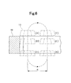
- FIG. 6 is a schematic view showing the method of controlling the machine tool according to the first embodiment of the present invention in machining a workpiece.
- the controller 40 performs control such that the cutter 13 may be moved in the order of [A] ⁇ [B] ⁇ [C] in a machining step, and moved in the order of [C] ⁇ [D] ⁇ [E] ⁇ [F] ⁇ [A] in a return step.
- the cutter 13 starts the machining of the workpiece 50 at a position indicated by [A] in Fig. 6 .
- a position indicated by [B] in Fig. 6 indicates a position of the cutter 13 during the machining of the workpiece 50.
- the cutter 13 terminates the machining of the workpiece 50 at a position indicated by [C] in Fig. 6 .
- the cutter 13 starts relieving R at the position indicated by [C] in Fig. 6 .
- the cutter 13 starts the relieving R upon the termination of the machining of the workpiece 50.
- the relieving interference is prevented by controlling the amount of rotation of the cutter 13 in the rotation direction C2, i.e., by performing control such that the cutter 13 may be moved away from the workpiece 50 in the rotation direction C2 (hereinafter referred to as offset control).
- offset control is performed by use of a specific phenomenon where, as shown in the relieving interference occurrence portion I (see Fig. 10 ), the relieving interference occurs in an extremely small area located in an upper half of the cutter 13 and the workpiece 50 in Fig. 10 but does not occur in a lower half thereof, in accordance with the rotation direction C2 of the cutter 13 and a rotation direction C1 of the workpiece 50 in machining.
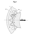
- Fig. 1 is a schematic view showing a method of preventing relieving interference in the machine tool according to the first embodiment of the present invention.
- the controller 40 performs, in synchronization with the relieving R, offset control such that relieving Rr in the rotation direction of the cutter 13 as shown in Fig. 1 may be performed in addition to the normal rotational movement of the cutter 13, and thereby substantially realizes target relieving Rt.
- a machine tool capable of causing the controller 40 to perform numerical control on the rotation angle of the cutter 13, can direct a direction of the target relieving Rt for a cutting blade 13a of the cutter 13 in the relieving interference portion I to a desired direction by performing offset control such that rotation by the amount corresponding to the relieving Rr in the rotation direction C2 of the cutter 13 may be additionally imposed on a position of the cutter 13 during the normal rotational movement in its rotation direction.
- the specifications of the workpiece are a module of 10, a pressure angle of 25°, the number of internal teeth of 46, a torsion direction of teeth being spur (straight cut gear), and a cut depth of 17.8 mm
- the specifications of the cutter are the number of blades of 15 and an outer diameter of 169.2 mm
- machining conditions are a circumferential feed of 0.278 mm/stroke and a radial feed of 0.015 mm/stroke.
- offset control is performed such that the cutter 13 may be moved away from the workpiece 50 in its rotation direction C2 by 0.3 mm (note that, this is a length on the circumference of a circle (PCD) connecting intermediate portions between the tips and the roots of the cutting blades 13a of the cutter 13 to each other, and is 0.23° when converted into the rotation angle).
- PCD circle
- the stroke means one reciprocating movement of the cutter 13, and indicates a path that the cutter 13 travels once along top dead center ⁇ [A] ⁇ [B] ⁇ [C] ⁇ bottom dead center ⁇ [D] ⁇ [E] ⁇ [F] ⁇ top dead center in Fig. 6 .
- the relieving interference portion I is briefly illustrated for the sake of understanding; however, the relieving interference actually occurs at multiple positions in the extremely small area located in the upper half of the cutter 13 and the workpiece 50 in Fig. 1 in accordance with the rotation direction C2 of the cutter 13 and the rotation direction C1 of the workpiece 50 in machining. Hence, the amount by which rotation is to be additionally imposed by the offset control on one occurrence position can be different from that on another occurrence position.
- Fig. 2 is a schematic view showing a method of controlling the cutter in relieving according to the first embodiment of the present invention. As shown in Fig. 2 , even if the relieving R is of fixed length, the machine tool according to this embodiment is capable of controlling a direction of the target relieving Rt by adjusting the amount of relieving Rr in the rotation direction of the cutter 13 by the offset control.
- control can be performed such that the target relieving Rt may be set to target relieving Rt' by setting the relieving Rr in the rotation direction of the cutter 13 to relieving Rr' in the rotation direction by the offset control.
- the controller 40 terminates the relieving R at a position indicated by [D] in Fig. 6 .
- the controller 40 controls the relieving Rr in the rotation direction of the cutter 13 at the positions indicated by [C] and [D] in Fig. 6 .
- a position indicated by [E] in Fig. 6 indicates a position of the cutter 13 during returning. Note that, in Fig. 6 , the amount of relieving is exaggeratingly shown for the sake of understanding.
- the cutter 13 makes an approach to the workpiece 50 (i.e., which is opposite to the relieving) at a position indicated by [F] in Fig. 6 .
- the controller 40 cancels the offset control at the positions indicated by [F] and [A] in Fig. 6 to return the position of the cutter 13 in the rotation direction C2 to the normal position thereof in the rotation movement.
- the cutter 13 starts the machining of the workpiece 50 at the position indicated by [A] in Fig. 6 .
- the machine tool is capable of controlling the target relieving Rt for the cutting blade 13a of the cutter 13 in the relieving interference portion I only by the control of the rotation angle of the cutter 13.
- Fig. 3 is a schematic view showing the method of controlling a cutter in relieving according to the second embodiment of the present invention. As shown in Fig.
- a machine tool capable of performing numerical control on the rotation angle of the cutter 13 and the amount of relieving of the cutter 13 in a relieving direction Rd can control a direction and magnitude (i.e., vector) of the target relieving Rt by adjusting the amount of relieving R in the relieving direction Rd and the amount of relieving Rr in the rotation direction of the cutter 13 by the offset control.
- control can be performed such that the target relieving Rt may be set to target relieving Rt" by setting the relieving R in the relieving direction Rd to relieving R' and setting the relieving Rr in the rotation direction of the cutter 13 by the offset control to the relieving Rr' in the rotation direction.
- target relieving Rt may be set to target relieving Rt" by setting the relieving R in the relieving direction Rd to relieving R' and setting the relieving Rr in the rotation direction of the cutter 13 by the offset control to the relieving Rr' in the rotation direction.
- the method of controlling the machine tool in the machine tool configured to machine the workpiece 50 to be machined by repeating the steps of: machining the workpiece 50 by moving the cutter 13 for machining the workpiece 50 in the vertical direction while rotating the workpiece 50 together with the cutter 13; and returning the cutter 13 to its machining start position again after termination of this machining step, offset control is performed such that the cutter 13 may be moved away from the workpiece 50 in its rotation direction upon the termination of the machining step.
- the method is capable of controlling the target relieving Rt for the cutting blade 13a of the cutter 13 in the relieving interference portion I only by the control of the rotation angle of the cutter 13.
- the relieving R is performed such that the cutter 13 may be moved away from the workpiece 50, and the amount by which the cutter 13 is moved away from the workpiece 50 in its rotation direction by the offset control is adjusted together with the relieving R.
- control can be performed such that the target relieving Rt may be set to the target relieving Rt' even if the relieving R is of fixed length.
- the relieving R' is performed such that the cutter 13 may be moved away from the workpiece 50, and the amount by which the cutter 13 is moved away from the workpiece 50 in its rotation direction by the offset control is adjusted together with the adjusting of the amount of the relieving R'.
- an optimum direction and magnitude of the target relieving Rt " can be achieved.
- the machine tool includes workpiece rotation means for rotating the workpiece 50 to be machined; cutter rotation means for rotating the cutter 13 for machining the workpiece 50; cutter vertical movement means for moving the cutter 13 in the vertical direction; relieving means for moving the cutter 13 away from the workpiece 50; and the controller 40 for controlling the workpiece rotation means, the cutter rotation means, the cutter vertical movement means, and the relieving means.
- the controller 40 performs control such that the workpiece 50 is machined by repeating the steps of: machining the workpiece 50 by moving the cutter 50 for machining the workpiece 50 in the vertical direction while rotating the workpiece 50 together with the cutter 13; and returning the cutter 13 to a machining start position again after termination of the machining step, and performs offset control such that the cutter 13 is moved away from the workpiece 50 in its rotation direction upon the termination of the machining step.
- the machine tool is capable of controlling the target relieving Rt for the cutting blade 13a of the cutter 13 in the relieving interference portion I only by the control of the rotation angle of the cutter 13.
- the controller 40 upon the termination of the machining step, performs control such that the relieving R may be performed in which the cutter 13 is moved away from the workpiece 50, and, together with the relieving R, adjusts the amount by which the cutter 13 is moved away from the workpiece 50 in its rotation direction by the offset control.
- control can be performed such that the target relieving Rt may be set to the target relieving Rt' even if the relieving R is of fixed length.
- the controller 40 performs control such that the relieving R' may be performed in which the cutter 13 is moved away from the workpiece 50, adjusts the amount of this relieving R', and adjusts the amount by which the cutter 13 is moved away from the workpiece 50 in its rotation direction by the offset control.
- the relieving R' may be performed in which the cutter 13 is moved away from the workpiece 50
- the controller 40 adjusts the amount of this relieving R', and adjusts the amount by which the cutter 13 is moved away from the workpiece 50 in its rotation direction by the offset control.
- the present invention can provide the method of controlling a machine tool and a machine tool which allow preventing relieving interference without using a mechanism for causing an offset between the cutter 13 and the workpiece 50.
- the present invention can be used for a method of controlling a machine tool and a machine tool, particularly for a method of controlling a machine tool configured to machine a workpiece into an internal gear and for a machine tool.
Landscapes
- Engineering & Computer Science (AREA)
- Mechanical Engineering (AREA)
- Gear Processing (AREA)
- Numerical Control (AREA)
- Machine Tool Units (AREA)
- Turning (AREA)
Abstract
To provide a method of controlling a machine tool and a machine tool which allow preventing relieving interference without using a mechanism for causing an offset between a cutter (13) and a workpiece (50) , a controller (40) performs control such that the workpiece (50) is machined by repeating the steps of: machining the workpiece (50) by moving the cutter (13) for machining the workpiece (50) in a direction parallel to a rotational axis of the cutter (50) while rotating the workpiece (50) together with the cutter (13); and returning the cutter (13) to a machining start position again after termination of the machining step, and performs offset control such that the cutter (13) is moved away from the workpiece (50) in a rotation direction of the cutter (13) upon the termination of the machining step.
Description
- The present invention relates to a method of controlling a machine tool and a machine tool.
- A gear shaper is a machine tool including a cutter reciprocating mechanism in which a working tool (hereinafter called cutter) is reciprocated in a center axis direction of an object to be machined (hereinafter called a workpiece.) so as to machine the workpiece in its advancing path and to be moved away from the workpiece in its returning path. Examples of such a gear shaper are disclosed in
Patent Documents 1 and 2 below. -
Fig. 7 is a schematic view showing how a workpiece is machined in a conventional gear shaper.
As shown inFig. 7 , for example, the gear shaper as disclosed inPatent Document 1 below performs gear cutting by shaping aworkpiece 50 in such a manner that acutter 13 attached to amain spindle 12 is given a rotational movement together with theworkpiece 50 while being reciprocated vertically (arrow L1 inFig. 7 ), theworkpiece 50 being placed on a table (not shown) on which theworkpiece 50 is attached for the machining. - The
cutter 13 is in a vertical state near its rising end ([a] inFig. 7 ). Thecutter 13 is moved straight downward in this state and machines theworkpiece 50 during the downward movement ([a] to [c] inFig. 7 ). Near its falling end, thecutter 13 is moved away (relieved) R from theworkpiece 50 in the arrow L2 direction by the amount of retraction (the amount of relieving) to become in a returning state ([d] inFig. 7 ). - Next, the
cutter 13 is moved upward in the state of [d]. Near its rising end, thecutter 13 approaches theworkpiece 50 by the amount of relieving to become in the vertical state ( [a] inFig. 7 ). Then, thecutter 13 is moved downward again. By repeating these operations, thecutter 13 machines theworkpiece 50 while being reciprocated vertically. - Here, the relieving direction of the cutter in relieving will be described.
Fig. 8 is a schematic view showing the relieving direction of the cutter in relieving.
As shown inFig. 8 ,cutting blades 13a are formed in a side surface of thecutter 13. The tip of eachcutting blade 13a is located on anaddendum circle 13b, and the root of eachcutting blade 13a is located on adedendum circle 13c.
Fig. 9 is a schematic view showing how an internal gear is formed by the cutter.
As shown inFig. 9 ,teeth 50a are formed in an inner surface of theworkpiece 50 by thecutter 13. Here, a portion indicated by a broken line in theworkpiece 50 is aportion 50d to be chipped. - As shown in
Fig. 8 , the tip of each formedtooth 50a is located on anaddendum circle 50b, and the root of eachtooth 50a is located on adedendum circle 50c. In relieving R, thecutter 13 is relieved R in a direction connecting the center O2 of thecutter 13 and the center O1 of theworkpiece 50. In other words, a direction from the center O2 of thecutter 13 toward the center O1 of theworkpiece 50 is a relieving direction Rd. - However, in the conventional gear shaper described above, the
cutter 13 and theworkpiece 50 during machining sometimes interfere with each other (hereinafter called relieving interference) in the relieving R of thecutter 13, depending on the specifications of the workpiece to be machined into an internal gear, the specifications of the cutter, machining conditions, and the like. - Here, the relieving interference will be described.
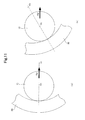
Fig. 10 is a schematic view showing how the relieving interference occurs.
As shown inFig. 10 , theworkpiece 50 during machining includes aportion 50e chipped this time and aportion 50f chipped in a previous rotation of theworkpiece 50. For example, at a portion indicated by I inFig. 10 , thecutter 13 in the relieving R as shown by a dashed-two dotted line inFig. 10 sometimes interferes with theportion 50f chipped in the previous rotation of theworkpiece 50. - Note that, in
Fig. 10 , the relieving interference portion I is briefly illustrated for the sake of understanding; however, the relieving interference actually occurs at multiple positions in an extremely small area between thecutter 13 and theworkpiece 50 inFig. 10 due to machining conditions such as the amount of cut, a cutting speed, and a feed speed. Moreover, if a rotation direction C2 of thecutter 13 and a rotation direction C1 of theworkpiece 50 during machining are as shown in the drawing, the interference does not occur in a lower half of the drawing but occurs in an upper half thereof. -
- Patent Document 1:
JP-A Hei 10-109223 - Patent Document 2:
JP-A 2004-154921 - In order to prevent the relieving interference, the relieving direction Rd shown in
Fig. 10 needs to be changed to a direction of target relieving Rt with which the interference between theworkpiece 50 and thecutter 13 shown inFig. 10 can be prevented. Thus, a method of causing a static offset in a relative position between thecutter 13 and theworkpiece 50 in a direction indicated by Y inFig. 10 is known as a method of changing the relieving direction Rd to the direction of the target relieving Rt. -
Fig. 11 is a schematic view showing a conventional method of changing the relieving direction Rd to the direction of the target relieving Rt.
As shown in Part (b) ofFig. 11 , the center O2 of thecutter 13 and the center O1 of theworkpiece 50 are shifted in the Y direction inFig. 10 while the relieving direction Rd shown in Part (a) ofFig. 11 is kept as it is. This causes the virtual center line of the machine tool originally directed in the relieving direction Rd to be directed in an O2O1 vector, and thus causes the relieving direction Rd to incline relative to the virtual center line. Thereby, the relieving direction Rd can be changed to the direction of the target relieving Rt. - However, for the above conventional method of changing the relieving direction Rd to the direction of the target relieving Rt, it is necessary to add a mechanism capable of causing an offset between the
cutter 13 and theworkpiece 50 in the Y direction inFig. 10 (seePatent Document 1, for example). This causes problems of complicating a machine configuration and increasing cost. - Thus, an object of the present invention is to provide a method of controlling a machine tool and a machine tool which allow preventing relieving interference without using a mechanism for causing an offset between a cutter and a workpiece.
- In a method of controlling a machine tool according to a first invention to solve the above problems, the machine tool is configured to machine a workpiece to be machined by repeating the steps of: machining the workpiece by moving a cutter for machining the workpiece in a direction parallel to a rotational axis of the cutter while rotating the workpiece together with the cutter; and returning the cutter to a machining start position again after termination of the machining step, the method characterized in that
upon the termination of the machining step, offset control is performed such that the cutter is moved away from the workpiece in a rotation direction of the cutter without change in a relative position of the rotational axis of the cutter with respect to the workpiece. - A method of controlling a machine tool according to a second invention to solve the above problems is the method of controlling a machine tool according to the first invention, characterized in that
upon the termination of the machining step, relieving is performed such that the cutter and the workpiece become away from each other by changing relative positions of the rotational axis of the cutter and a rotational axis of the workpiece with respect to each other, and, together with the relieving, the amount by which the cutter is moved away from the workpiece in the rotation direction thereof by the offset control is adjusted, thereby controlling a direction of target relieving. - A method of controlling a machine tool according to a third invention to solve the above problems is the method of controlling a machine tool according to the first invention, characterized in that
upon the termination of the machining step, relieving is performed such that the cutter is moved away from the workpiece, the amount of the relieving is adjusted, and the amount by which the cutter is moved away from the workpiece in the rotation direction thereof by the offset control is adjusted, thereby controlling a direction and magnitude of target relieving. - A machine tool according to a fourth invention to solve the above problems is a machine tool comprising:
- workpiece rotation means for rotating a workpiece to be machined;
- cutter rotation means for rotating a cutter for machining the workpiece;
- cutter reciprocation means for moving the cutter in a direction parallel to a rotational axis of the cutter;
- relieving means for moving the cutter away from the workpiece; and
- control means for controlling the workpiece rotation means, the cutter rotation means, the cutter reciprocation means, and the relieving means, the machine tool characterized in that
- the control means
performs control such that the workpiece is machined by repeating the steps of: machining the workpiece by moving the cutter for machining the workpiece in the direction parallel to the rotational axis of the cutter while rotating the workpiece together with the cutter; and returning the cutter to a machining start position again after termination of the machining step, and
performs offset control such that the cutter is moved away from the workpiece in a rotation direction of the cutter upon the termination of the machining step. - A machine tool according to a fifth invention to solve the above problems is the machine tool according to the fourth invention, characterized in that the control means
performs control such that relieving is performed in which the cutter is moved away from the workpiece upon the termination of the machining step, and
adjusts the amount by which the cutter is moved away from the workpiece in the rotation direction thereof by the offset control together with the relieving, thereby controlling a direction of target relieving. - A machine tool according to a sixth invention to solve the above problems is the machine tool according to the fourth invention, characterized in that
the control means
performs control such that relieving is performed in which the cutter is moved away from the workpiece upon the termination of the machining step, and
adjusts the amount of the relieving and the amount by which the cutter is moved away from the workpiece in the rotation direction thereof by the offset control, thereby controlling a direction and magnitude of target relieving. - The present invention can provide a method of controlling a machine tool and a machine tool which allow preventing relieving interference without using a mechanism for causing an offset between a cutter and a workpiece.
-
- [
Fig. 1] Fig. 1 is a schematic view showing a method of preventing relieving interference in a machine tool according to a first embodiment of the present invention. - [
Fig. 2] Fig. 2 is a schematic view showing a method of controlling a cutter in relieving according to the first embodiment of the present invention. - [
Fig. 3] Fig. 3 is a schematic view showing a method of controlling a cutter in relieving according to a second embodiment of the present invention. - [
Fig. 4] Fig. 4 is a schematic view showing principal portions of the machine tool according to the first embodiment of the present invention. - [
Fig. 5] Fig. 5 is a cross-sectional view showing the principal portions of the machine tool according to the first embodiment of the present invention. - [
Fig. 6] Fig. 6 is a schematic view showing a method of controlling the machine tool according to the first embodiment of the present invention in machining a workpiece. - [
Fig. 7] Fig. 7 is a schematic view showing how a workpiece is machined in a conventional gear shaper. - [
Fig. 8] Fig. 8 is a schematic view showing a relieving direction of a cutter in relieving. - [
Fig. 9] Fig. 9 is a schematic view showing how an internal gear is formed by the cutter. - [
Fig. 10] Fig. 10 is a schematic view showing how relieving interference occurs. - [
Fig. 11] Fig. 11 is a schematic view showing a conventional method of changing a relieving direction Rd to a direction of target relieving Rt. - Hereinbelow, a method of controlling a machine tool and a machine tool according to embodiments of the present invention will be described with reference to the drawings.
- First of all, description will be given of a structure of a machine tool according to a first embodiment of the present invention.
Fig. 4 is a schematic view showing principal portions of the machine tool according to the first embodiment of the present invention.Fig. 5 is a cross-sectional view showing the principal portions of the machine tool according to the first embodiment of the present invention.
As shown inFigs. 4 and5 , in the machine tool according to this embodiment, acutter head 10 is supported on a not-shown machine tool main body through asupport 11 to be movable in a horizontal direction inFigs. 4 and5 . - A
main spindle 12 is placed in thecutter head 10 to extend in a vertical direction inFigs. 4 and5 . Agear 14 is attached to themain spindle 12. Themain spindle 12 has such a structure as to be slidable in thegear 14 in the vertical direction and to be rotated in its rotation direction together with thegear 14. Themain spindle 12 is rotated with the rotation of thegear 14. - The
gear 14 is driven by a mainspindle driving motor 41 through agear 42. It is preferable to use a servomotor as the mainspindle driving motor 41. The use of the servomotor as the mainspindle driving motor 41 allows control of a rotation angle of acutter 13 with high speed and high accuracy. Thecutter 13 is attached to a lower end portion of themain spindle 12, and is rotated in a C2 direction. - In a portion above the cutter head 10A, a
crankshaft 19, acamshaft 25, and aneccentric shaft 29 are placed in the machine tool main body to be rotatable about their respective shaft centers. Acrank faceplate portion 20 is attached to thecrankshaft 19. Thecrank faceplate portion 20 is rotated about acenter 20A of thecrank faceplate portion 20 by the rotation of thecrankshaft 19. - A sliding
portion 17 is placed on thecrank faceplate portion 20 to be movable on a surface of thecrank faceplate portion 20 with aball screw 22. An end portion of acrank arm 15 is attached to the slidingportion 17 through apin 18. Thecrank arm 15 is swingable about thepin 18. - Further, the
center 20A of the crank faceplate portion and the center of thepin 18 are attached to be eccentric to each other. The amount of eccentricity between thecenter 20A of thecrank faceplate portion 20 and the center of thepin 18 can be adjusted by adjusting theball screw 22 to move the slidingportion 17 on the crank faceplate portion. The amount of eccentricity between thecenter 20A of the crank faceplate portion and the center of thepin 18 is associated with the length of the vertical reciprocating movement of themain spindle 12, i.e., the larger the amount of eccentricity, the longer the length of the vertical reciprocating movement of themain spindle 12. The other end portion of thecrank arm 15 is attached to an upper end portion of themain spindle 12 through aspherical bearing 16. - Further, a
motor 35 for main spindle reciprocating movement is coupled to thecrankshaft 19 throughgears motor 35 for main spindle reciprocating movement. The use of the servomotor as themotor 35 for main spindle reciprocating movement allows control of thecrankshaft 19 with high speed and high accuracy. - A
camshaft driving motor 36 is coupled to thecamshaft 25 throughgears camshaft driving motor 36. The use of the servomotor as thecamshaft driving motor 36 allows control of a rotation angle of thecamshaft 25 with high speed and high accuracy, and also allows control of thecamshaft driving motor 36 in synchronization with control of themotor 35 for main spindle reciprocating movement. - Further, a
cam 26 is attached to thecamshaft 25. Thecam 26 is also rotated with the rotation of thecamshaft 25. Thecam 26 is constituted of two cams overlapping with each other or formed in one unit with their phases (angles) shifted from each other. These two cams are normal cams each having a shape in which the radius of the cam changes in a circumferential direction thereof. The shape of thecam 26 causes the amount, by which thecutter 13 moves backward from or moves forward to a workpiece, to be changed in accordance with the rotation angle of thecamshaft 25. - An eccentric
shaft faceplate portion 33 is attached to theeccentric shaft 29, and is rotatable in a Y2 direction about acenter 33A of the eccentricshaft faceplate portion 33 in conjunction with the movement of theeccentric shaft 29. An end portion of a relievingrod 30 is attached to the eccentricshaft faceplate portion 33 through apin 32 in such a way that thecenter 33A and the center of thepin 32 are eccentric to each other. The other end portion of the relievingrod 30 is attached to a left end portion of thecutter head 10 in the drawing through apin 31 in such a way that thecutter head 10 is movable in the horizontal direction inFigs. 4 and5 . - Further, a
cam lever 28 is attached to the eccentricshaft faceplate portion 33 to be rotatable about thecenter 33A. Twocam followers 27 are attached to thecam lever 28. The twocam followers 27 are in contact with thecam 26 to interpose thecam 26 between them. One of thecam followers 27 is in contact only with the outer circumference of one of the two cams in thecam 26 having a shape constituted of these cams overlapping with each other or formed in one unit. Meanwhile, theother cam follower 27 is in contact only with the outer circumference of the other cam. - When the
cam 26 is rotated, a distance between the center of thecam 26 and eachcam follower 27 changes, so that thecam lever 28 is rotated about thecenter 33A in the Y2 direction. In conjunction with the rotation of thecam lever 28, theeccentric shaft 29 and the eccentricshaft faceplate portion 33 are rotated about thecenter 33A in the Y2 direction.
These are the structure of the machine tool according to the first embodiment of the present invention. - Next, description will be given of an operation of the machine tool according to the first embodiment of the present invention.
Acontroller 40 performs numerical control on the mainspindle driving motor 41, themotor 35 for main spindle reciprocating movement, and thecamshaft driving motor 36. Thecontroller 40 issues a desired synchronous instruction, which is suited to a shape into which aworkpiece 50 is to be machined, to the mainspindle driving motor 41, themotor 35 for main spindle reciprocating movement, and thecamshaft driving motor 36, and thereby performs synchronous control thereon with high speed and high accuracy. - When the
motor 35 for main spindle reciprocating movement rotates in a direction, thecrankshaft 19 coupled to themotor 35 for main spindle reciprocating movement is rotated in a direction. With the rotation of thecrankshaft 19, thecrank faceplate portion 20 and the slidingportion 17 are rotated about thecrankshaft 19, so that thecrank arm 15 is vertically reciprocated. In conjunction with the vertical movement of thecrank arm 15, thecutter 13 is vertically reciprocated in a Y1 direction. - The length of the vertical reciprocating movement of the
cutter 13 is determined by the amount of eccentricity between the center of thecrankshaft 19 and the center of thepin 18. In the changing of the length of the vertical reciprocating movement of themain spindle 12, theball screw 22 is adjusted to move the slidingportion 17 and to thereby adjust the amount of eccentricity between the center of thecrankshaft 19 and the center of thepin 18, so that the length of the vertical reciprocating movement can be changed. - In response to the given synchronous instruction issued by the
controller 40 and suited to the shape into which theworkpiece 50 is to be machined, thecamshaft driving motor 36 rotates in a desired direction in synchronization with the rotation of themotor 35 for main spindle reciprocating movement, and thereby rotates thecamshaft 25 so that the rotation angle of thecamshaft 25 may reach a desired angle. With the rotation of thecamshaft driving motor 36, thecamshaft 25 coupled to thecamshaft driving motor 36 is rotated. In conjunction with the rotation of thecamshaft 25, thecam lever 28 and the eccentricshaft faceplate portion 33 are rotated about thecenter 33A in the Y2 direction. - In conjunction with the rotational movement of the eccentric
shaft faceplate portion 33, the relievingrod 30 is reciprocated in a Y3 direction. In conjunction with the reciprocating movement of the relievingrod 30, thecutter head 10 is moved in the horizontal direction inFigs. 4 and5 . In conjunction with the movement of thecutter head 10 in the horizontal direction inFigs. 4 and5 , thecutter 13 can move forward to or move backward from theworkpiece 50. In this way, the machine tool according to this embodiment can be operated as desired by thecontroller 40.
These are the operation of the machine tool according to the first embodiment of the present invention. - Next, description will be given of the method of controlling the machine tool according to the first embodiment of the present invention in machining a workpiece.
Fig. 6 is a schematic view showing the method of controlling the machine tool according to the first embodiment of the present invention in machining a workpiece. As shown inFig. 6 , thecontroller 40 performs control such that thecutter 13 may be moved in the order of [A] → [B] → [C] in a machining step, and moved in the order of [C] → [D] → [E] → [F] → [A] in a return step. - In the machining step, the
cutter 13 starts the machining of theworkpiece 50 at a position indicated by [A] inFig. 6 . A position indicated by [B] inFig. 6 indicates a position of thecutter 13 during the machining of theworkpiece 50. Then, thecutter 13 terminates the machining of theworkpiece 50 at a position indicated by [C] inFig. 6 . - In the return step, the
cutter 13 starts relieving R at the position indicated by [C] inFig. 6 . In other words, thecutter 13 starts the relieving R upon the termination of the machining of theworkpiece 50. - According to this embodiment, the relieving interference is prevented by controlling the amount of rotation of the
cutter 13 in the rotation direction C2, i.e., by performing control such that thecutter 13 may be moved away from theworkpiece 50 in the rotation direction C2 (hereinafter referred to as offset control). Such control is performed by use of a specific phenomenon where, as shown in the relieving interference occurrence portion I (seeFig. 10 ), the relieving interference occurs in an extremely small area located in an upper half of thecutter 13 and theworkpiece 50 inFig. 10 but does not occur in a lower half thereof, in accordance with the rotation direction C2 of thecutter 13 and a rotation direction C1 of theworkpiece 50 in machining. - Here, description will be given of a method of preventing relieving interference in the machine tool according to the first embodiment of the present invention.
Fig. 1 is a schematic view showing a method of preventing relieving interference in the machine tool according to the first embodiment of the present invention.
As shown inFig. 1 , thecontroller 40 performs, in synchronization with the relieving R, offset control such that relieving Rr in the rotation direction of thecutter 13 as shown inFig. 1 may be performed in addition to the normal rotational movement of thecutter 13, and thereby substantially realizes target relieving Rt. - In other words, a machine tool capable of causing the
controller 40 to perform numerical control on the rotation angle of thecutter 13, such as the machine tool according to this embodiment, can direct a direction of the target relieving Rt for acutting blade 13a of thecutter 13 in the relieving interference portion I to a desired direction by performing offset control such that rotation by the amount corresponding to the relieving Rr in the rotation direction C2 of thecutter 13 may be additionally imposed on a position of thecutter 13 during the normal rotational movement in its rotation direction. - For example, suppose a case where the specifications of the workpiece are a module of 10, a pressure angle of 25°, the number of internal teeth of 46, a torsion direction of teeth being spur (straight cut gear), and a cut depth of 17.8 mm, where the specifications of the cutter are the number of blades of 15 and an outer diameter of 169.2 mm, and where machining conditions are a circumferential feed of 0.278 mm/stroke and a radial feed of 0.015 mm/stroke. In this case, in order to prevent the relieving interference in the relieving interference portion I as illustrated in
Fig. 1 , offset control is performed such that thecutter 13 may be moved away from theworkpiece 50 in its rotation direction C2 by 0.3 mm (note that, this is a length on the circumference of a circle (PCD) connecting intermediate portions between the tips and the roots of thecutting blades 13a of thecutter 13 to each other, and is 0.23° when converted into the rotation angle). - Here, the stroke means one reciprocating movement of the
cutter 13, and indicates a path that thecutter 13 travels once along top dead center → [A] → [B] → [C] → bottom dead center → [D] → [E] → [F] → top dead center inFig. 6 . - Note that, in
Fig. 1 , the relieving interference portion I is briefly illustrated for the sake of understanding; however, the relieving interference actually occurs at multiple positions in the extremely small area located in the upper half of thecutter 13 and theworkpiece 50 inFig. 1 in accordance with the rotation direction C2 of thecutter 13 and the rotation direction C1 of theworkpiece 50 in machining. Hence, the amount by which rotation is to be additionally imposed by the offset control on one occurrence position can be different from that on another occurrence position. -
Fig. 2 is a schematic view showing a method of controlling the cutter in relieving according to the first embodiment of the present invention.
As shown inFig. 2 , even if the relieving R is of fixed length, the machine tool according to this embodiment is capable of controlling a direction of the target relieving Rt by adjusting the amount of relieving Rr in the rotation direction of thecutter 13 by the offset control. - In other words, even if the relieving R is of fixed length, control can be performed such that the target relieving Rt may be set to target relieving Rt' by setting the relieving Rr in the rotation direction of the
cutter 13 to relieving Rr' in the rotation direction by the offset control.
These are the method of preventing the relieving interference in the machine tool according to the first embodiment of the present invention. - As shown in
Fig. 6 , thecontroller 40 terminates the relieving R at a position indicated by [D] inFig. 6 . Thecontroller 40 controls the relieving Rr in the rotation direction of thecutter 13 at the positions indicated by [C] and [D] inFig. 6 . A position indicated by [E] inFig. 6 indicates a position of thecutter 13 during returning. Note that, inFig. 6 , the amount of relieving is exaggeratingly shown for the sake of understanding. - The
cutter 13 makes an approach to the workpiece 50 (i.e., which is opposite to the relieving) at a position indicated by [F] inFig. 6 . Thecontroller 40 cancels the offset control at the positions indicated by [F] and [A] inFig. 6 to return the position of thecutter 13 in the rotation direction C2 to the normal position thereof in the rotation movement. Then, thecutter 13 starts the machining of theworkpiece 50 at the position indicated by [A] inFig. 6 .
These are the method of controlling the machine tool in the machining of the workpiece according to the first embodiment of the present invention. - Thus, although the conventional gear shaper has to control the target relieving Rt by causing an offset between the
cutter 13 and theworkpiece 50 in the Y direction inFig. 10 , the machine tool according to this embodiment is capable of controlling the target relieving Rt for thecutting blade 13a of thecutter 13 in the relieving interference portion I only by the control of the rotation angle of thecutter 13. - Accordingly, a conventionally required mechanism to cause an offset between the
cutter 13 and theworkpiece 50 in the Y direction inFig. 10 is no longer required. This simplifies a machine configuration and reduces cost.
Moreover, the method of preventing the relieving interference in the machine tool according to this embodiment can be implemented only by changing a program for thecontroller 40, which in turn reduces cost. - Hereinbelow, description will be given of a method of controlling a machine tool in relieving according to a second embodiment of the present invention. Note that, the configuration of the machine tool according to this embodiment is the same as that of the first embodiment.
Fig. 3 is a schematic view showing the method of controlling a cutter in relieving according to the second embodiment of the present invention.
As shown inFig. 3 , a machine tool capable of performing numerical control on the rotation angle of thecutter 13 and the amount of relieving of thecutter 13 in a relieving direction Rd, such as the machine tool according to this embodiment, can control a direction and magnitude (i.e., vector) of the target relieving Rt by adjusting the amount of relieving R in the relieving direction Rd and the amount of relieving Rr in the rotation direction of thecutter 13 by the offset control. - In other words, control can be performed such that the target relieving Rt may be set to target relieving Rt" by setting the relieving R in the relieving direction Rd to relieving R' and setting the relieving Rr in the rotation direction of the
cutter 13 by the offset control to the relieving Rr' in the rotation direction. Hence, an optimum vector of the target relieving Rt" can be achieved.
These are the method of controlling the machine tool in relieving according to the second embodiment of the present invention. - As has been described, with the method of controlling the machine tool according to the present invention, in the machine tool configured to machine the
workpiece 50 to be machined by repeating the steps of: machining theworkpiece 50 by moving thecutter 13 for machining theworkpiece 50 in the vertical direction while rotating theworkpiece 50 together with thecutter 13; and returning thecutter 13 to its machining start position again after termination of this machining step, offset control is performed such that thecutter 13 may be moved away from theworkpiece 50 in its rotation direction upon the termination of the machining step. Thereby, the method is capable of controlling the target relieving Rt for thecutting blade 13a of thecutter 13 in the relieving interference portion I only by the control of the rotation angle of thecutter 13. - Accordingly, a conventionally required mechanism to cause an offset between the
cutter 13 and theworkpiece 50 in the Y direction inFig. 10 is no longer required. This simplifies a machine configuration and reduces cost.
Moreover, the method of preventing the relieving interference in the machine tool according to this embodiment can be implemented only by changing a program for thecontroller 40, which in turn reduces cost. - Further, upon the termination of the machining step, the relieving R is performed such that the
cutter 13 may be moved away from theworkpiece 50, and the amount by which thecutter 13 is moved away from theworkpiece 50 in its rotation direction by the offset control is adjusted together with the relieving R. Thereby, control can be performed such that the target relieving Rt may be set to the target relieving Rt' even if the relieving R is of fixed length. - Further, upon the termination of the machining step, the relieving R' is performed such that the
cutter 13 may be moved away from theworkpiece 50, and the amount by which thecutter 13 is moved away from theworkpiece 50 in its rotation direction by the offset control is adjusted together with the adjusting of the amount of the relieving R'. Thereby, an optimum direction and magnitude of the target relieving Rt " can be achieved. - Furthermore, the machine tool according to the present invention includes workpiece rotation means for rotating the
workpiece 50 to be machined; cutter rotation means for rotating thecutter 13 for machining theworkpiece 50; cutter vertical movement means for moving thecutter 13 in the vertical direction; relieving means for moving thecutter 13 away from theworkpiece 50; and thecontroller 40 for controlling the workpiece rotation means, the cutter rotation means, the cutter vertical movement means, and the relieving means. In the machine tool, thecontroller 40 performs control such that theworkpiece 50 is machined by repeating the steps of: machining theworkpiece 50 by moving thecutter 50 for machining theworkpiece 50 in the vertical direction while rotating theworkpiece 50 together with thecutter 13; and returning thecutter 13 to a machining start position again after termination of the machining step, and performs offset control such that thecutter 13 is moved away from theworkpiece 50 in its rotation direction upon the termination of the machining step. Thereby, the machine tool is capable of controlling the target relieving Rt for thecutting blade 13a of thecutter 13 in the relieving interference portion I only by the control of the rotation angle of thecutter 13. - Accordingly, a conventionally required mechanism to cause an offset between the
cutter 13 and theworkpiece 50 in the Y direction inFig. 10 is no longer required. This simplifies a machine configuration and reduces cost.
Moreover, the method of preventing the relieving interference in the machine tool according to this embodiment can be implemented only by changing a program for thecontroller 40, which in turn reduces cost. - Further, upon the termination of the machining step, the
controller 40 performs control such that the relieving R may be performed in which thecutter 13 is moved away from theworkpiece 50, and, together with the relieving R, adjusts the amount by which thecutter 13 is moved away from theworkpiece 50 in its rotation direction by the offset control. Thereby, control can be performed such that the target relieving Rt may be set to the target relieving Rt' even if the relieving R is of fixed length. - Further, upon the termination of the machining step, the
controller 40 performs control such that the relieving R' may be performed in which thecutter 13 is moved away from theworkpiece 50, adjusts the amount of this relieving R', and adjusts the amount by which thecutter 13 is moved away from theworkpiece 50 in its rotation direction by the offset control. Thereby, an optimum direction and magnitude of the target relieving Rt " can be achieved. - Therefore, the present invention can provide the method of controlling a machine tool and a machine tool which allow preventing relieving interference without using a mechanism for causing an offset between the
cutter 13 and theworkpiece 50. - The present invention can be used for a method of controlling a machine tool and a machine tool, particularly for a method of controlling a machine tool configured to machine a workpiece into an internal gear and for a machine tool.
-
- 10
- cutter head
- 11
- support
- 12
- main spindle
- 13
- cutter
- 14
- gear
- 15
- crank arm
- 16
- spherical bearing
- 17
- sliding portion
- 18
- pin
- 19
- crankshaft
- 20
- crank faceplate portion
- 22
- ball screw
- 23, 24
- gear
- 25
- camshaft
- 26
- cam
- 27
- cam follower
- 28
- cam lever
- 29
- eccentric shaft
- 30
- relieving rod
- 31, 32
- pin
- 33
- eccentric shaft faceplate portion
- 35
- motor for main spindle reciprocating movement
- 36
- camshaft driving motor
- 37, 38
- gear
- 40
- controller
- 41
- main spindle driving motor
- 42
- gear
- 50
- work
Claims (6)
- A method of controlling a machine tool configured to machine a workpiece to be machined by repeating the steps of: machining the workpiece by moving a cutter for machining the workpiece in a direction parallel to a rotational axis of the cutter while rotating the workpiece together with the cutter; and returning the cutter to a machining start position again after termination of the machining step, the method characterized in that
upon the termination of the machining step, offset control is performed such that the cutter is moved away from the workpiece in a rotation direction of the cutter without change in a relative position of the rotational axis of the cutter with respect to the workpiece. - The method of controlling a machine tool according to claim 1, characterized in that
upon the termination of the machining step, relieving is performed such that the cutter and the workpiece become away from each other by changing relative positions of the rotational axis of the cutter and a rotational axis of the workpiece with respect to each other, and, together with the relieving, the amount by which the cutter is moved away from the workpiece in the rotation direction thereof by the offset control is adjusted, thereby controlling a direction of target relieving. - The method of controlling a machine tool according to claim 1, characterized in that
upon the termination of the machining step, relieving is performed such that the cutter is moved away from the workpiece, the amount of the relieving is adjusted, and the amount by which the cutter is moved away from the workpiece in the rotation direction thereof by the offset control is adjusted, thereby controlling a direction and magnitude of target relieving. - A machine tool comprising:workpiece rotation means for rotating a workpiece to be machined;cutter rotation means for rotating a cutter for machining the workpiece;cutter reciprocation means for moving the cutter in a direction parallel to a rotational axis of the cutter;relieving means for moving the cutter away from the workpiece; andcontrol means for controlling the workpiece rotation means, the cutter rotation means, the cutter reciprocation means, and the relieving means, the machine tool characterized in thatthe control means
performs control such that the workpiece is machined by repeating the steps of: machining the workpiece by moving the cutter for machining the workpiece in the direction parallel to the rotational axis of the cutter while rotating the workpiece together with the cutter; and returning the cutter to a machining start position again after termination of the machining step, and
performs offset control such that the cutter is moved away from the workpiece in a rotation direction of the cutter upon the termination of the machining step. - The machine tool according to claim 4, characterized in that
the control means
performs control such that relieving is performed in which the cutter is moved away from the workpiece upon the termination of the machining step, and
adjusts the amount by which the cutter is moved away from the workpiece in the rotation direction thereof by the offset control together with the relieving, thereby controlling a direction of target relieving. - The machine tool according to claim 4, characterized in that
the control means
performs control such that relieving is performed in which the cutter is moved away from the workpiece upon the termination of the machining step, and
adjusts the amount of the relieving and the amount by which the cutter is moved away from the workpiece in the rotation direction thereof by the offset control, thereby controlling a direction and magnitude of target relieving.
Applications Claiming Priority (2)
| Application Number | Priority Date | Filing Date | Title |
|---|---|---|---|
| JP2008311762A JP5308136B2 (en) | 2008-12-08 | 2008-12-08 | Machine tool control method and machine tool |
| PCT/JP2009/069337 WO2010067690A1 (en) | 2008-12-08 | 2009-11-13 | Method of controlling machine tool and machine tool |
Publications (1)
| Publication Number | Publication Date |
|---|---|
| EP2368660A1 true EP2368660A1 (en) | 2011-09-28 |
Family
ID=42242682
Family Applications (1)
| Application Number | Title | Priority Date | Filing Date |
|---|---|---|---|
| EP09831796A Withdrawn EP2368660A1 (en) | 2008-12-08 | 2009-11-13 | Method of controlling machine tool and machine tool |
Country Status (7)
| Country | Link |
|---|---|
| US (1) | US8936417B2 (en) |
| EP (1) | EP2368660A1 (en) |
| JP (1) | JP5308136B2 (en) |
| CN (1) | CN102307694B (en) |
| BR (1) | BRPI0920978A2 (en) |
| TW (1) | TWI454328B (en) |
| WO (1) | WO2010067690A1 (en) |
Cited By (3)
| Publication number | Priority date | Publication date | Assignee | Title |
|---|---|---|---|---|
| DE102019004299A1 (en) * | 2019-06-17 | 2020-12-17 | Gleason-Pfauter Maschinenfabrik Gmbh | Method for gear shaping of a periodic structure, in particular a toothing and shaping machine designed for this purpose |
| CN112672838A (en) * | 2018-10-10 | 2021-04-16 | 西铁城时计株式会社 | Machine tool |
| WO2022207309A1 (en) * | 2021-04-01 | 2022-10-06 | Gleason-Pfauter Maschinenfabrik Gmbh | Method for gear shaping a toothing, control program, and gear shaping machine for carrying out the method |
Families Citing this family (7)
| Publication number | Priority date | Publication date | Assignee | Title |
|---|---|---|---|---|
| US8251620B2 (en) * | 2007-03-02 | 2012-08-28 | GM Global Technology Operations LLC | Method and system to manufacture oriented internal and external gear teeth |
| US9447727B2 (en) * | 2010-12-24 | 2016-09-20 | Mark William Klarer | Variable displacement engine |
| JP5693685B2 (en) * | 2013-09-06 | 2015-04-01 | 三菱重工業株式会社 | Gear processing machine |
| CN111712343B (en) * | 2018-03-30 | 2024-06-25 | 西铁城时计株式会社 | machine tool |
| CN110479839B (en) * | 2019-08-02 | 2020-08-04 | 武汉理工大学 | A method for obtaining parameters of enveloping rolls for forming thin-walled and high-rib cylindrical components |
| CN114571283A (en) * | 2022-03-07 | 2022-06-03 | 新代科技(苏州)有限公司 | Cutter retracting method used in machining |
| CN116466648B (en) * | 2023-04-12 | 2025-11-21 | 上海汽车变速器有限公司 | Automatic control method for machine tool, machine tool and storage medium |
Family Cites Families (10)
| Publication number | Priority date | Publication date | Assignee | Title |
|---|---|---|---|---|
| DE1627379A1 (en) * | 1967-04-08 | 1970-05-14 | Zahnradfabrik Friedrichshafen | Gear hobbing machine |
| DE2042929B2 (en) * | 1970-08-29 | 1972-10-19 | Maschinenfabrik Lorenz Ag, 7505 Ettlingen | WHEEL SHAPING MACHINE FOR GEARS O DGL WITH ADJUSTABLE RELATIVE ROTATION ANGLE POSITION OF WORKPIECE AND TOOL DURING THE ROLLING PROCESS |
| JPS6085823A (en) * | 1983-10-18 | 1985-05-15 | Mitsubishi Heavy Ind Ltd | Gear shaper with relieving interference detecting function |
| JPS6294219A (en) * | 1985-10-18 | 1987-04-30 | Mitsubishi Heavy Ind Ltd | Positioning method for radial feed direction in numerically controlled gear shaper |
| SU1641534A1 (en) * | 1988-05-03 | 1991-04-15 | Новополоцкий Политехнический Институт Им.Ленинского Комсомола Белоруссии | Method for hobbing gears |
| EP0557561A1 (en) * | 1992-02-28 | 1993-09-01 | International Business Machines Corporation | Serial data link utilising NRZI and Manchester code |
| JPH10109223A (en) * | 1996-10-04 | 1998-04-28 | Mitsubishi Heavy Ind Ltd | Gear shaver |
| TW582317U (en) * | 1997-07-07 | 2004-04-01 | Mitsubishi Heavy Ind Ltd | Gear shaper cutting apparatus |
| JP2004154921A (en) * | 2002-11-08 | 2004-06-03 | Mitsubishi Heavy Ind Ltd | Machine tool |
| DE102006052474A1 (en) * | 2006-11-07 | 2008-05-08 | Liebherr-Verzahntechnik Gmbh | Roller shaping machine for manufacturing or processing gear wheel, has direct drive for moving shaping drive transverse to shaping direction, and measuring system arranged at direct drive and monitoring movement of direct drive |
-
2008
- 2008-12-08 JP JP2008311762A patent/JP5308136B2/en active Active
-
2009
- 2009-11-13 CN CN2009801560027A patent/CN102307694B/en active Active
- 2009-11-13 BR BRPI0920978A patent/BRPI0920978A2/en not_active IP Right Cessation
- 2009-11-13 EP EP09831796A patent/EP2368660A1/en not_active Withdrawn
- 2009-11-13 US US13/133,310 patent/US8936417B2/en active Active
- 2009-11-13 WO PCT/JP2009/069337 patent/WO2010067690A1/en not_active Ceased
- 2009-11-18 TW TW098139154A patent/TWI454328B/en not_active IP Right Cessation
Non-Patent Citations (1)
| Title |
|---|
| See references of WO2010067690A1 * |
Cited By (6)
| Publication number | Priority date | Publication date | Assignee | Title |
|---|---|---|---|---|
| CN112672838A (en) * | 2018-10-10 | 2021-04-16 | 西铁城时计株式会社 | Machine tool |
| CN112672838B (en) * | 2018-10-10 | 2024-03-26 | 西铁城时计株式会社 | Machine tool |
| DE102019004299A1 (en) * | 2019-06-17 | 2020-12-17 | Gleason-Pfauter Maschinenfabrik Gmbh | Method for gear shaping of a periodic structure, in particular a toothing and shaping machine designed for this purpose |
| WO2020254114A1 (en) | 2019-06-17 | 2020-12-24 | Gleason-Pfauter Maschinenfabrik Gmbh | Method for gear shaping a periodic structure, in particular a toothing, and shaping machine designed therefor |
| US12472568B2 (en) | 2019-06-17 | 2025-11-18 | Gleason-Pfauter Maschinenfabrik Gmbh | Method for gear shaping a periodic structure, in particular a toothing, and shaping machine designed therefor |
| WO2022207309A1 (en) * | 2021-04-01 | 2022-10-06 | Gleason-Pfauter Maschinenfabrik Gmbh | Method for gear shaping a toothing, control program, and gear shaping machine for carrying out the method |
Also Published As
| Publication number | Publication date |
|---|---|
| JP5308136B2 (en) | 2013-10-09 |
| BRPI0920978A2 (en) | 2016-01-05 |
| TWI454328B (en) | 2014-10-01 |
| CN102307694B (en) | 2013-05-29 |
| US20110262239A1 (en) | 2011-10-27 |
| TW201032926A (en) | 2010-09-16 |
| US8936417B2 (en) | 2015-01-20 |
| WO2010067690A1 (en) | 2010-06-17 |
| JP2010131729A (en) | 2010-06-17 |
| CN102307694A (en) | 2012-01-04 |
Similar Documents
| Publication | Publication Date | Title |
|---|---|---|
| US8936417B2 (en) | Method of controlling machine tool and machine tool | |
| KR101913918B1 (en) | Cutter for skiving | |
| US8961268B2 (en) | Method for hard fine machining of the tooth flanks of a gear wheel | |
| RU2088385C1 (en) | Machine for machining slots in part hole | |
| JP4216519B2 (en) | Cylinder inner surface processing method and processing apparatus | |
| KR101407557B1 (en) | Arrangement for cutting nail blanks from an intermittently fed wire | |
| US20230158591A1 (en) | Method for machining a tooth flank region of a workpiece tooth arrangement, chamfering tool, control program having control instructions for carrying out the method, and gear-cutting machine | |
| EP1502688B1 (en) | Method and machine for cutting spiral bevel gears | |
| JP5549527B2 (en) | Grooving method | |
| CN105612018B (en) | Gear Processing Machinery | |
| US6264531B1 (en) | Machine for machining work pieces with cutting teeth, especially saw blades | |
| US9919371B2 (en) | Gear machining apparatus | |
| KR102930274B1 (en) | Method for machining and producing a gear tooth on a workpiece | |
| JP2004154921A (en) | Machine tool | |
| JP2024520080A (en) | Method for machining the tooth flank area of a workpiece tooth row, chamfering tool, control program with control instructions for carrying out said method, and gear cutting machine - Patents.com | |
| JP2018161735A (en) | Control device for machine tool and machine tool | |
| US12472568B2 (en) | Method for gear shaping a periodic structure, in particular a toothing, and shaping machine designed therefor | |
| KR100191290B1 (en) | Improvements in or relating to slotting machines | |
| CN102615360B (en) | Hydraulic numerical control system of gear shaping machine | |
| CN113579369B (en) | Method for machining a tooth tip diameter and tool for producing a gearwheel | |
| US20020081163A1 (en) | Stroking speed adjustment for shaping machine | |
| JP4208162B2 (en) | Gear shaping with NC lathe | |
| CN106985005B (en) | Cam grinding device and cam grinding method | |
| KR102382441B1 (en) | Complex Serration Machining Unit for Roughing and Finishing | |
| SU221468A1 (en) | SEMI-AUTOMATIC MACHINES FOR PROCESSING GATES FOR CREATING |
Legal Events
| Date | Code | Title | Description |
|---|---|---|---|
| PUAI | Public reference made under article 153(3) epc to a published international application that has entered the european phase |
Free format text: ORIGINAL CODE: 0009012 |
|
| 17P | Request for examination filed |
Effective date: 20110526 |
|
| AK | Designated contracting states |
Kind code of ref document: A1 Designated state(s): AT BE BG CH CY CZ DE DK EE ES FI FR GB GR HR HU IE IS IT LI LT LU LV MC MK MT NL NO PL PT RO SE SI SK SM TR |
|
| DAX | Request for extension of the european patent (deleted) | ||
| STAA | Information on the status of an ep patent application or granted ep patent |
Free format text: STATUS: THE APPLICATION HAS BEEN WITHDRAWN |
|
| 18W | Application withdrawn |
Effective date: 20150814 |