EP2368603B1 - Method and apparatus for distributing fire suppressant - Google Patents
Method and apparatus for distributing fire suppressant Download PDFInfo
- Publication number
- EP2368603B1 EP2368603B1 EP11171159.4A EP11171159A EP2368603B1 EP 2368603 B1 EP2368603 B1 EP 2368603B1 EP 11171159 A EP11171159 A EP 11171159A EP 2368603 B1 EP2368603 B1 EP 2368603B1
- Authority
- EP
- European Patent Office
- Prior art keywords
- suppressant
- valves
- communication
- apertures
- control valve
- Prior art date
- Legal status (The legal status is an assumption and is not a legal conclusion. Google has not performed a legal analysis and makes no representation as to the accuracy of the status listed.)
- Expired - Lifetime
Links
- 238000000034 method Methods 0.000 title description 4
- 238000004891 communication Methods 0.000 claims abstract description 62
- XPDWGBQVDMORPB-UHFFFAOYSA-N Fluoroform Chemical compound FC(F)F XPDWGBQVDMORPB-UHFFFAOYSA-N 0.000 claims description 4
- 239000000126 substance Substances 0.000 claims description 4
- YFMFNYKEUDLDTL-UHFFFAOYSA-N 1,1,1,2,3,3,3-heptafluoropropane Chemical compound FC(F)(F)C(F)C(F)(F)F YFMFNYKEUDLDTL-UHFFFAOYSA-N 0.000 claims description 2
- CURLTUGMZLYLDI-UHFFFAOYSA-N Carbon dioxide Chemical compound O=C=O CURLTUGMZLYLDI-UHFFFAOYSA-N 0.000 claims description 2
- 125000006342 heptafluoro i-propyl group Chemical group FC(F)(F)C(F)(*)C(F)(F)F 0.000 claims description 2
- 238000009826 distribution Methods 0.000 description 14
- 239000000463 material Substances 0.000 description 8
- 230000001629 suppression Effects 0.000 description 7
- 238000004880 explosion Methods 0.000 description 6
- 239000003795 chemical substances by application Substances 0.000 description 5
- 239000007789 gas Substances 0.000 description 5
- 230000009471 action Effects 0.000 description 3
- IJGRMHOSHXDMSA-UHFFFAOYSA-N Atomic nitrogen Chemical compound N#N IJGRMHOSHXDMSA-UHFFFAOYSA-N 0.000 description 2
- 229920006362 Teflon® Polymers 0.000 description 2
- 230000004913 activation Effects 0.000 description 2
- 230000000903 blocking effect Effects 0.000 description 2
- 229910052799 carbon Inorganic materials 0.000 description 2
- 239000006260 foam Substances 0.000 description 2
- 239000007788 liquid Substances 0.000 description 2
- 238000000926 separation method Methods 0.000 description 2
- 229910000906 Bronze Inorganic materials 0.000 description 1
- OKTJSMMVPCPJKN-UHFFFAOYSA-N Carbon Chemical compound [C] OKTJSMMVPCPJKN-UHFFFAOYSA-N 0.000 description 1
- 229910000975 Carbon steel Inorganic materials 0.000 description 1
- 229920004943 Delrin® Polymers 0.000 description 1
- 229920002449 FKM Polymers 0.000 description 1
- 230000003213 activating effect Effects 0.000 description 1
- 230000003466 anti-cipated effect Effects 0.000 description 1
- 238000013459 approach Methods 0.000 description 1
- 238000003491 array Methods 0.000 description 1
- 230000015572 biosynthetic process Effects 0.000 description 1
- 239000010974 bronze Substances 0.000 description 1
- 239000010962 carbon steel Substances 0.000 description 1
- 230000008859 change Effects 0.000 description 1
- 238000010276 construction Methods 0.000 description 1
- KUNSUQLRTQLHQQ-UHFFFAOYSA-N copper tin Chemical compound [Cu].[Sn] KUNSUQLRTQLHQQ-UHFFFAOYSA-N 0.000 description 1
- 238000007599 discharging Methods 0.000 description 1
- 230000009977 dual effect Effects 0.000 description 1
- 230000000694 effects Effects 0.000 description 1
- 239000012530 fluid Substances 0.000 description 1
- 239000000446 fuel Substances 0.000 description 1
- 239000011521 glass Substances 0.000 description 1
- 238000004519 manufacturing process Methods 0.000 description 1
- 238000005259 measurement Methods 0.000 description 1
- 239000000203 mixture Substances 0.000 description 1
- 230000007935 neutral effect Effects 0.000 description 1
- 229910052757 nitrogen Inorganic materials 0.000 description 1
- 238000003908 quality control method Methods 0.000 description 1
- 230000002787 reinforcement Effects 0.000 description 1
- 238000009877 rendering Methods 0.000 description 1
- 230000004044 response Effects 0.000 description 1
- 239000007787 solid Substances 0.000 description 1
- 239000010935 stainless steel Substances 0.000 description 1
- 229910001220 stainless steel Inorganic materials 0.000 description 1
Images




Classifications
-
- A—HUMAN NECESSITIES
- A62—LIFE-SAVING; FIRE-FIGHTING
- A62C—FIRE-FIGHTING
- A62C35/00—Permanently-installed equipment
- A62C35/58—Pipe-line systems
- A62C35/68—Details, e.g. of pipes or valve systems
-
- Y—GENERAL TAGGING OF NEW TECHNOLOGICAL DEVELOPMENTS; GENERAL TAGGING OF CROSS-SECTIONAL TECHNOLOGIES SPANNING OVER SEVERAL SECTIONS OF THE IPC; TECHNICAL SUBJECTS COVERED BY FORMER USPC CROSS-REFERENCE ART COLLECTIONS [XRACs] AND DIGESTS
- Y10—TECHNICAL SUBJECTS COVERED BY FORMER USPC
- Y10T—TECHNICAL SUBJECTS COVERED BY FORMER US CLASSIFICATION
- Y10T137/00—Fluid handling
- Y10T137/8593—Systems
- Y10T137/86493—Multi-way valve unit
- Y10T137/86863—Rotary valve unit
Definitions
- the invention relates to an apparatus and method for distributing fire suppressant.
- the invention relates more particularly to an apparatus and method for delivering a fire suppressant selected from among one or more available suppressants to any combination of one or more suppressant distributors.
- a single suppressant source may be connected to a single control valve, which is then connected to a distributor that is in the area where suppressant is to be distributed.
- the control valve is opened, whereupon suppressant flows from the suppressant source to the distributor, and thus to the fire (see e.g. US 4 002 148 ).
- the system 10 includes four suppressant sources 20, 22, 24, and 26.
- the suppressant sources are all in communication (i.e. via a line, pipe, or tube) with a series of control valves 30, 32, 34, 36, and 38.
- Each of the control valves connects to a suppressant distributor 40, 42, 44, 46, and 48 (not shown).
- the arrangement of control valves and connecting lines is sometimes referred to collectively as a discharge manifold.
- Each of the control valves in this conventional arrangement defines two apertures therein: 30A and 30B; 32A and 32B; 34A and 34B; 36A and 36B; and 38A and 38B.
- Each control valve is movable between two positions, closed and open. In the closed position, the two apertures of the control valves are not in communication with one another. In the open position, the two apertures are in communication. Consequently, for the configuration shown, in the closed position the control valves 30, 32, 34, 36, and 38 do. not pass suppressant, while in the open position, they do.
- Figure 1 shows all of the control valves 30, 32, 34, 36, and 38 in their closed positions, as might be typical when the system is inactive.
- Figure 2 shows control valve 38 in the open position. Given the positions of the control valves in Figure 2 , apertures 38A and 38B are in communication, thus suppressant from one or more of the sources 20, 22, 24, and 26 (depending on which was open) would pass through control valve 38 to distributor 48.
- dead space diverts suppressant from the location where it is actually needed.
- the quantity of suppressant that is discharged from each distributor be predictable to within established tolerances of the desired discharge quantity and discharge time.
- portions of the manifold may be unnecessarily filled with suppressant.
- the dead space in a system may be vented or discharged, in some cases the agent will not immediately discharge within a proscribed time period (i.e. 10 seconds). This affects the operation of the system; the effects must either be ignored and accepted, or compensated for in other ways.
- the amount of dead space is large (i.e. in a large manifold, with long lines between the suppressant sources 20 , 22 , 24 , and 26 and the most distant of the control valves 30 , 32 , 34 , 36 , and 38 ), this may substantially increase the amount of suppressant that must be used when the system is activated.
- the volume of the dead space may be large enough to require an increased pressure at the sources 20 , 22 , 24 , and 26 when activating the system, so as to maintain adequate distribution pressure at the open distributor 38.
- An exemplary embodiment of an apparatus in accordance with the principles of the claimed invention includes at least one suppressant source, at least one control valve in communication with the suppressant source, and at least one distributor, each distributor being in communication with at least one control valve.
- the control valves each define first, second, and third apertures therein.
- the control valves are each movable between first, second, and third positions.
- the first and third apertures of each valve are in communication with one another.
- the first, second, and third apertures of each valve are in communication with one another.
- control valves may be movable to a fourth position, as well. In the fourth position, the first and second apertures of each valve are in communication with one another.
- This feature enables not only discharge of suppressant through each control valve, but also direction of suppressant both through each control valve, without actually discharging through a distributor connected thereto. As a result, it is possible to discharge suppressant from any one or more of the distributors, in any combination.
- each of the control valves passes suppressant therethrough, but does not pass suppressant to its distributor.
- each of the control valves does not pass suppressant therethrough, but passes suppressant to its distributor.
- each of the control valves passes suppressant therethrough, and passes suppressant to its distributor.
- a suppressing system in accordance with the principles of the claimed invention may be made to direct suppressant from the suppressant source (or from any one of several suppressant sources) to any combination of the distributors.
- control valves maybe movable to a fourth position, as well.
- each of the control valves in the fourth position does not pass suppressant therethrough, and does not pass suppressant to its distributor.
- T control valve such as a three-way through T directional disk valve, or a three-way through T directional ball valve.
- T control valve such as a three-way through T directional disk valve, or a three-way through T directional ball valve.
- this is exemplary only, and other valves may be equally suitable.
- an apparatus 110 for fire suppression in accordance with the principles of the claimed invention includes at least one fire suppressant source. As shown in Figures 3 and 5-7 , the apparatus has four fire suppressant sources 120 , 122 , 124 , and 126. However, this is exemplary only.
- the sources 120 , 122 , 124 , and 126 may be single tanks, such as might be used for a superpressurized agent system.
- the sources 120 , 122 , 124 , and 126 may be double tanks, such as might be used with a piston-flow system.
- tanks 120A , 122A , 124A , and 126A contain the suppressant proper, while tanks 120B , 122B , 124B , and 126B contain a pressurizing fluid, such as compressed nitrogen.
- suppressants include, but are not limited to, gasses, liquids, granular solids, and foams.
- suitable fire suppressants include, but are not limited to, liquefied compressed gas chemical extinguishing agents, such as HFC-227ea, HFC-23, CO 2 , and CF 3 CF 2 C(O)CF(CF 3 ) 2 .
- liquefied compressed gas chemical extinguishing agents such as HFC-227ea, HFC-23, CO 2 , and CF 3 CF 2 C(O)CF(CF 3 ) 2 .
- liquefied compressed gas chemical extinguishing agents such as HFC-227ea, HFC-23, CO 2 , and CF 3 CF 2 C(O)CF(CF 3 ) 2 .
- liquefied compressed gas chemical extinguishing agents such as HFC-227ea, HFC-23, CO 2 , and CF 3 CF 2 C(O)CF(CF 3 ) 2 .
- the specific suppressants identified herein are exemplary only. Suppressants other than those named may be equally suitable.
- Each suppressant source may supply a different suppressant.
- some or all of the suppressant sources may supply identical suppressants.
- Fire suppressants are well known, and are not described further herein.
- fire suppression is used broadly. Firstly, “fire” encompasses both slow-burning conventional fires and explosions. Furthermore, “suppression” encompasses not only actions to extinguish or diminish a fire or explosion once it begins, but also actions to counteract a fire or explosion that is imminent, as well as to prevent fires and explosions under conditions wherein their formation is likely but not certain.
- fire suppression may include the distribution of fire suppressant to a location wherein a combustible gas is detected, even if no fire or explosion has yet occurred. This preemptive action is sometimes referred to as "inerting", as it is done to render an area inert with respect to fire and explosion.
- the suppressant sources 120 , 122 , 124 , and 126 are in communication with at least one control valve.
- Each of the control valves defines first, second, and third apertures therein: 130A , 130B , and 130C ; 132A , 132B , and 132C ; 134A , 134B , and 134C ; 136A , 136B, and 136C ; and 138A , 138B , and 138C.
- Each of the control valves 130 , 132 , 134 , 136 , and 138 is movable between at least three of first, second, third, and fourth positions.
- the first and third apertures of each valve are in communication with one another.
- the first, second, and third apertures of each valve are in communication with one another.
- control valves may be movable to all four of these positions.
- control valves that are not movable to all four positions, which three of the four above positions the control valves are movable may vary based on the particulars of the embodiments in question, and the arrangement of the control valves therein. Generally, the three positions are determined by the specific desired function of each individual control valve, i.e. in what direction(s) suppressant is to be passed by the control valve in question.
- control valves in a given embodiment will necessarily be movable to the same three positions. Likewise, not all control valves will pass suppressant in the same direction(s).
- control valves may be described based on their functionality, i.e. in what directions suppressant is passed.
- each control valve in the first position, passes suppressant therethrough (i.e., to the next control valve "downstream"), but does not pass suppressant to a distributor (see below) in communication with the control valve.
- each control valve does not pass suppressant therethrough, but passes suppressant to a distributor in communication therewith.
- each control valve passes suppressant therethrough, and passes suppressant to a distributor in communication with the control valve.
- each control valve does not pass suppressant therethrough, and does not pass suppressant to a distributor in communication with the control valve.
- control valves that produces the above-identified functional results is exemplary only.
- the control valves may be arranged otherwise, so that different positions may result in different distributions of suppressant.
- valves shown herein are illustrated in schematic form. Actual valves may include various internal components, i.e. a valve body, a rotor, o-rings, seals, port connectors, etc. Valves are known per se, and the mechanical structure of valves in general is not described in detail herein.
- control valves 130 , 132 , 134 , 136 , and 138 are in the first position.
- this may be considered a neutral or standby position.
- the control valves may remain in this position when not otherwise specifically moved to other positions.
- this is exemplary only.
- Each control valve 130 , 132 , 134 , 136 , and 138 is in communication with at least one distributor 140 , 142 , 144 , 146 , and 148. More particularly, one of the apertures of each control valve is in communication with the distributors. As illustrated, the second apertures 130B , 132B , 134B , 136B , and 138B are in communication with distributors 140, 142, 144, 146, and 148. However, this is exemplary only, and other arrangements may be equally suitable.
- each control valve 130,132, 134, 136, and 138 is in communication with exactly one distributor, 140,142,144, 146, and 148, in certain embodiments a control valve may be in communication with multiple distributors.
- distributors may be suitable for use with the claimed invention.
- the precise structure and arrangement of the distributors will depend on both the type of suppressant that is used, and the type of fire (i.e. anticipated location, size, fuel type, etc.) that is to be suppressed.
- Suitable distributors include, but are not limited to, gas discharge vents, liquid atomizers, foam sprayers, and granular distribution heads.
- Suitable connectors include, but are not limited to, rigid pipe, flexible hose, tubing, and conduits. Not all connectors need be the same. For example, some of the connectors in a particular embodiment may be flexible hose, while others are rigid pipe.
- control valves 130, 132, 134, 136, and 138 may include additional valves, which may be connected differently from control valves 130,132, 134,136, and 138, and which may also function differently.
- valves 150,152,154, and 156 that separate each of the suppressant sources 120, 122, 124, and 126 from the remainder of the manifold.
- Such valves may serve to prevent back flow, that is, the flow of a suppressant from one suppressant source into another source. Back flow is a particular concern when some, but not all, of the suppressant sources discharge.
- Valves 150, 152, 154, and 156 may also serve to reduce dead space, by blocking off portions of the manifold that are not in use when some, but not all, of the suppressant sources discharge.
- such valves may also serve to lock off the suppressant sources, so as to prevent accidental discharge of suppressant.
- valves including but not limited to El-check valves, may be suitable for this application. However, this is exemplary only.
- valves 162, 164, and 166 may also be valves 162, 164, and 166 that separate the individual suppressant sources 120, 122, 124, and 126 from one another. Such valves may also serve to prevent back flow. Valves 162, 164, and 166 may also serve to reduce dead space, by blocking off portions of the manifold that are not in use when some, but not all, of the suppressant sources discharge.
- valves including but not limited to swing check and check valves, may be suitable for this application. However, this is exemplary only.
- Swing check and check valves and other suitable valves are well known, and are not described further herein.
- additional valves are exemplary only. Embodiments with other arrangements of such additional valves, or without additional valves at all, may be equally suitable.
- valves 150, 152, 154, and 156 and valves 162, 164, and 166 are known per se.
- Figures 1 and 2 similarly show valves 50, 52, 54, and 56 and valves 62, 64, and 66 in prior art devices.
- each of the control valves 130, 132, 134, 136, and 138 is movable between at least first, second, and third positions, and may be movable to a fourth position as well.
- Figures 8A-D show a single valve, 130, in each of the first, second, third, and fourth positions, respectively.
- Figure 4 shows a schematic representation of control valves 130, 132, 134, 136, and 138 in various positions, and the results of each arrangement for the embodiment illustrated in Figure 3 .
- suppressant reaching the valve may not actually go anywhere.
- control valve 130 is in the first position, so that the first and third apertures 130A and 130C are in communication, there is nowhere for suppressant to go after passing through control valve 130.
- the positions of the valve but also the configuration of the apparatus 10 as a whole, influences the particular manner in which suppressant can be distributed.
- control valve 130 is in the second position, while control valves 132, 134, 136, and 138 are in the first position. Control valves 132, 134, 136, and 138 pass suppressant therethrough, but do not pass it to their distributors 142, 144, 146, and 148. However, control valve 130 still passes suppressant to distributor 140.
- control valve 132 is in the second position, while control valves 130, 134, 136, and 138 are in the first position. Control valves 134, 136, and 138 pass suppressant therethrough, but do not pass it to their distributors 144, 146, and 148. Control valve 132 passes suppressant to distributor 142. However, control valve 132 does not pass suppressant therethrough, so no suppressant reaches control valve 130. Thus, suppressant is delivered only to distributor 142, and there is no dead space, i.e. no space beyond valves 132 that is unnecessarily filled with unused suppressant.
- Figure 4D is similar to arrangements B and C, in that one control valve is in the second position, while the other control valves are in the first position.
- control valve 136 is in the second position, while control valves 130, 132, 134, and 138 are in the first position.
- Control valve 138 passes suppressant therethrough, but does not pass it to distributor 148.
- Control valve 136 passes suppressant to distributor 146.
- control valve 136 does not pass suppressant therethrough, so no suppressant reaches control valves 130, 132, or 134.
- suppressant is delivered only to distributor 146, and there is no dead space beyond control valve 136.
- control valve 138 is in the third position, so as to pass suppressant both through itself and to distributor 148.
- Control valves 134 and 136 are in the first position, so as to pass suppressant therethrough.
- suppressant is passed to control valve 132.
- Control valve 132 is in the second position, passing suppressant to distributor 142.
- suppressant is delivered to both distributors 142 and 148, but not to any of the other distributors. Furthermore, there is no dead space beyond control valve 132.
- case E may be generalized to other arrangements, wherein suppressant is to be delivered to any two or more of the distributors 140,142,144,146, and 148.
- control valve 134 is in the fourth position.
- Control valve 134 does not pass suppressant either to other control valves downstream, or to distributor 144.
- suppressant will not reach distributors 130 and 132.
- Such a configuration may be useful during servicing, in cases wherein some portion of the system 110 is malfunctioning, or where it is desired to override the distribution of suppressant to some or all of the distributors 140, 142, 144, 146, and 148.
- the use of a fourth position is exemplary only, and embodiments wherein some or all of the control valves 130, 132, 134, 136, and 138 are not movable to a fourth position may be equally suitable.
- suppressant may be sent to any one or more of the distributors 140, 142, 144, 146, and 148, without any dead space.
- any one or more of the suppressants may be directed to any one or more of the distributors, without any dead space.
- valves may be suitable for use in an apparatus according to the principles of the claimed invention.
- One exemplary valve that is suitable for use as a control valve in the claimed invention is a so-called "T control valve", such as a three-way through T directional disk valve.
- a disk with three passages that connect to form a T is rotatably set into a housing having at least three openings. As the disk is rotated, the three passages are brought into alignment with various of the openings in the housing. As a result, with the proper arrangement of disk passages and housing openings, three-way through T directional disk valves may be made to pass material straight through, or to divert it in different directions, or to do both simultaneously.
- A.A refers to a measurement of the valve size.
- 3 indicates a 3-aperture valve.
- B and C indicate the material of the valve body and the rotor therein respectively, typically bronze, stainless steel, or carbon steel.
- D indicates the material of the o-ring seals, typically TEFLON®, VITON®, and/or Bune-N.
- T indicates a T-type configuration of apertures in the rotor.
- E indicates the material of the seal material, typically TEFLON® (with or without glass reinforcement), DELRIN®, or carbon-filled TFE.
- FF indicates the type of end connections, typically female national pipe thread, 150# flange, TRI-CLAMP®, CHERRY-BURRELL I-LINE® (female), socket weld, butt weld sch #10 or #40 pipe, or male acme bevel seat.
- G indicates special ordering features, and HH represents a bill of materials number.
- valves in a particular embodiment of an apparatus for fire suppression in accordance with the principles of the claimed invention will depend on (among other things) the intended application of that embodiment, i.e. the local environment, the type of fires to be suppressed, the type of suppressant used, etc. Thus, citing one or even several actual specific valve part numbers may not be useful or even meaningful, even for exemplary purposes.
- part numbers are indicative of the broad range of actual valve structures, materials, etc. that may be suitable for use with the present invention, and likewise is indicative of the broad range of potential embodiments and applications for the present invention overall.
- valves presented above are exemplary only, and that the present invention is not limited thereto.
- a wide variety of other valves including but not limited to other three-way through T directional disk valves, may be equally suitable.
- Three-way through T directional disk valves are known per se, and are not described further herein.
- control valves 130, 132, 134, 136, and 138 in Figures 3-8 are illustrated as schematic renderings of three-way through T directional disk valves.
- the three-way through T directional disk valves in Figures 3-5 are arranged with 90 degree separations between the three passages, and likewise with 90 degree separations between three openings in the housing.
- this is exemplary only, and other arrangements may be equally suitable.
- T directional disk valves As previously noted, the use of three-way through T directional disk valves is itself exemplary, and other valves may be equally suitable.
- valves include, but are not limited to, three way through T directional ball valves.
- Three-way through T directional ball valves are schematically similar to three-way through T directional disk valves, except that a ball is used in place of a disk. Many of the comments made above with regard to ball valves apply equally to disk valves.
- T directional disk valves Three-way through T directional disk valves are known per se, and are not described further herein.
- control valves are arranged in a single line, this is exemplary only. More complex arrangements are possible, including but not limited to multiple independent lines of valves, and interconnecting parallel lines or arrays of valves.
- Figure 6 shows an embodiment of an apparatus 110 for fire suppression in accordance with the principles of the claimed invention with a dual arrangement of control valves and distributors.
- the embodiment of Figure 6 includes control valves 131,133,135,137, and 139 and distributors 141, 143, 145, 147, and 149.
- the two groups of control valves and distributors are connected to the suppressant sources 120, 122, 124, and 126 in two lines, in an arrangement somewhat analogous to that of a parallel electrical circuit.
- control valves 131, 133,135,137, and 139 determine which of the distributors 141, 143, 145, 147, and 149 receivers suppressant.
- Suppressant may be supplied to any one or more of the distributors.
- control valve 170 disposed between the two lines of control valves and the suppressant sources.
- This valve is similar in structure and function to control valves 130, 131, 132, 133, 134, 135, 136, 137, 138, and 139 that are in communication with the distributors.
- control valve 170 defines first, second, and third apertures 170A, 170B, and 170C therein, and is movable between at least three of first, second, third, and fourth positions.
- first and third apertures of each valve are in communication with one another.
- second position the second and third apertures of each valve are in communication with one another.
- third position the first, second, and third apertures of each valve are in communication with one another.
- fourth position the first and second apertures of each valve are in communication with one another.
- control valve 170 may be movable to all four of the positions described above.
- control valve 170 is in communication with the suppressant sources and with other control valves.
- control valve 170 can direct suppressant to control valves 130,132,134,136, and 138, or to control valves 131, 133, 135, 137, and 139, or to both groups of control valves, or to none, depending on its position.
- control valve 170 which result is produced in which position depends at least in part upon the arrangement of control valve 170 in the particular embodiment under consideration.
- the first and third apertures 170A and 170C are in communication, and no suppressant will flow from the suppressant sources to the other control valves.
- the second and third apertures 170A and 170C are communication, and suppressant may flow only to control valves 131, 133, 135, 137, and 139.
- the first, second, and third apertures are in communication, and suppressant may flow to both sets of control valves.
- the first and second apertures 170A and 170C are communication, and suppressant may flow only to control valves 130, 132, 134, 136, and 138.
- Control valve 170 may serve functions similar to the other control valves. For example, it can limit dead space within the manifold, and can help to control which (if any) distributors receive suppressant.
- control valve 170 it is emphasized, with reference to the example of further control valve 170, that the claimed invention is not limited to using control valves as described herein solely for direct control of distributors. Rather, as with control valve 170, similar control valves may be disposed at any T-junction in the apparatus 110.
- each of the control valves 130, 131, 132, 133, 134, 135, 136, 137, 138, and 139 also is located at a T-junction, where a line for carrying suppressant branches into three directions.
- control valve 170 is not necessarily in direct communication with either distributors or suppressant sources.
- control valve 170 is in communication with suppressant sources 120, 122, 124, and 126.
- this is exemplary only. Indeed, in certain embodiments, it may be advantageous to include further control valves that are only in communication with other control valves.
- control valves at T-junctions within the apparatus 110 is exemplary only. Embodiments having one or more T-junctions that do not include control valves may be equally suitable.
- Figure 7 shows an exemplary embodiment of an apparatus in accordance with the principles of the claimed invention. The embodiment illustrated in Figure 7 is similar to that in Figure 3 , except that control valve 130 is omitted.
- the apparatus 110 of Figure 7 retains the functionality of that shown in Figure 3 . Namely, it is still possible to distribute suppressant to any one or more of the distributors 140, 142, 144, 146, and 148. In particular, depending on the position of control valve 132, suppressant may be directed to either, both, or neither of distributors 140 and 142.
- Figure 6 shows control valves and distributors arranged symmetrically, in a mirror image arrangement, this is exemplary only.
- a single control valve may control the operation of more than one distributor.
- embodiments wherein multiple control valves are used to control a single distributor may also be advantageous.
- the suppressant sources are arranged together in a single line, this also is exemplary only. Embodiments wherein the suppressant sources are arranged differently, in particular where they are arranged in two or more separate groups or where they are distributed in a more complex arrangement than that of a single line, may be equally suitable.
Landscapes
- Health & Medical Sciences (AREA)
- Public Health (AREA)
- Business, Economics & Management (AREA)
- Emergency Management (AREA)
- Fire-Extinguishing By Fire Departments, And Fire-Extinguishing Equipment And Control Thereof (AREA)
- Multiple-Way Valves (AREA)
- Respiratory Apparatuses And Protective Means (AREA)
Abstract
Description
- This application is being filed on 18 September 2003, as a PCT International Patent application in the names of James Bowyer (United Kingdom citizen and United States resident), Robert Dunster (United Kingdom citizen and resident), David S. Rausch and William Mahony (United States citizens and residents) applicants for all countries.
- The invention relates to an apparatus and method for distributing fire suppressant.
- The invention relates more particularly to an apparatus and method for delivering a fire suppressant selected from among one or more available suppressants to any combination of one or more suppressant distributors.
- A variety of materials are known that can suppress fires. In general, these fire suppressants must be distributed in the immediate vicinity of the fire in order to be effective. Several conventional approaches for distributing fire suppressants are known.
- First, a single suppressant source may be connected to a single control valve, which is then connected to a distributor that is in the area where suppressant is to be distributed. In response to a fire, the control valve is opened, whereupon suppressant flows from the suppressant source to the distributor, and thus to the fire (see e.g.
US 4 002 148 ). - This arrangement, while simple, has a number of disadvantages, one of the more serious being that it a requires a dedicated system for each location, i.e. a source of suppressant must be provided for each area that is to be protected. This is often impractical or undesirable.
- It is also known to connect one or more fire suppressant sources with a series of control valves, each control valve being connected with a distributor. Such an arrangement is illustrated in
Figures 1 and2 . - In the arrangement illustrated, the
system 10 includes foursuppressant sources control valves suppressant distributor - Each of the control valves in this conventional arrangement defines two apertures therein: 30A and 30B; 32A and 32B; 34A and 34B; 36A and 36B; and 38A and 38B. Each control valve is movable between two positions, closed and open. In the closed position, the two apertures of the control valves are not in communication with one another. In the open position, the two apertures are in communication. Consequently, for the configuration shown, in the closed position the
control valves -
Figure 1 shows all of thecontrol valves Figure 2 showscontrol valve 38 in the open position. Given the positions of the control valves inFigure 2 ,apertures sources control valve 38 todistributor 48. - In such an arrangement, multiple distributors in multiple locations can be supplied by a single set of suppressant sources. However, this arrangement also has disadvantages.
- For example, when any one of the
control valves Figure 2 , suppressant would flow all the way to controlvalve 30. The portion of the system that is filled, but does not need to be filled, is sometimes referred to as "dead space". Such an arrangement is undesirable for several reasons. - For example, dead space diverts suppressant from the location where it is actually needed. In order for a fire suppressant distribution system to be effective, it is important that the quantity of suppressant that is discharged from each distributor be predictable to within established tolerances of the desired discharge quantity and discharge time. In a conventional system as shown in
Figures 1 and2 , portions of the manifold may be unnecessarily filled with suppressant. Although in some cases the dead space in a system may be vented or discharged, in some cases the agent will not immediately discharge within a proscribed time period (i.e. 10 seconds). This affects the operation of the system; the effects must either be ignored and accepted, or compensated for in other ways. - In cases where the amount of dead space is large (i.e. in a large manifold, with long lines between the
suppressant sources control valves sources open distributor 38. - Furthermore, after each activation of such a system, it may be necessary to clean and/or service the entire manifold from the
suppressant sources control valves - There exists a need for a system that enables distribution of suppressant to any of several available distributors, without unnecessarily filling large unused portions of the system during each activation.
- It is the purpose of the claimed invention to overcome these difficulties, thereby providing an improved apparatus and method for distributing fire suppressant.
- An exemplary embodiment of an apparatus in accordance with the principles of the claimed invention includes at least one suppressant source, at least one control valve in communication with the suppressant source, and at least one distributor, each distributor being in communication with at least one control valve.
- The control valves each define first, second, and third apertures therein. The control valves are each movable between first, second, and third positions.
- In the first position, the first and third apertures of each valve are in communication with one another.
- In the second position, the second and third apertures of each valve are in communication with one another.
- In the third position, the first, second, and third apertures of each valve are in communication with one another.
- In addition, in certain embodiments the control valves may be movable to a fourth position, as well. In the fourth position, the first and second apertures of each valve are in communication with one another.
- This feature enables not only discharge of suppressant through each control valve, but also direction of suppressant both through each control valve, without actually discharging through a distributor connected thereto. As a result, it is possible to discharge suppressant from any one or more of the distributors, in any combination.
- For example, in the exemplary embodiment illustrated in
Figure 3 , in the first position, each of the control valves passes suppressant therethrough, but does not pass suppressant to its distributor. - In the second position, each of the control valves does not pass suppressant therethrough, but passes suppressant to its distributor.
- In the third position, each of the control valves passes suppressant therethrough, and passes suppressant to its distributor.
- Thus, depending upon the positions of the control valves, a suppressing system in accordance with the principles of the claimed invention may be made to direct suppressant from the suppressant source (or from any one of several suppressant sources) to any combination of the distributors.
- As noted above, in certain embodiments the control valves maybe movable to a fourth position, as well. In the arrangement of
Figure 3 , in the fourth position each of the control valves does not pass suppressant therethrough, and does not pass suppressant to its distributor. - One possible valve that is suitable for use as a control valve in the claimed invention is a so-called "T control valve", such as a three-way through T directional disk valve, or a three-way through T directional ball valve. However, this is exemplary only, and other valves may be equally suitable.
- Like reference numbers generally indicate corresponding elements in the figures.
-
Figure 1 is a schematic representation of a conventional suppressant distribution system, as known from the prior art, with all control valves in the closed position. -
Figure 2 is another view of the conventional suppressant distribution system shown inFigure 1 , with one of the control valves in the open position. -
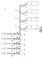
Figure 3 is a schematic representation of an exemplary embodiment of a suppressant distribution system in accordance with the principles of the claimed invention. -
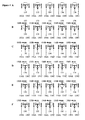
Figures 4A-F illustrate a schematic representation of control valves in the embodiment ofFigure 3 , shown in various positions. -
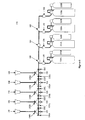
Figure 5 is a schematic representation of another exemplary embodiment of a suppressant distribution system in accordance with the principles of the claimed invention, having double tank suppressant sources. -
Figure 6 is a schematic representation of still another exemplary embodiment of a suppressant distribution system in accordance with the principles of the claimed invention, having multiple discharge lines. -
Figure 7 is a schematic representation of yet another exemplary embodiment of a suppressant distribution system in accordance with the principles of the claimed invention, having a single control valve controlling more than one distributor. -
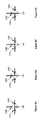
Figures 8A-D illustrate a schematic representation of a single control valve in accordance with the principles of the claimed invention, in each of four positions. - Referring to
Figure 3 , anapparatus 110 for fire suppression in accordance with the principles of the claimed invention includes at least one fire suppressant source. As shown inFigures 3 and5-7 , the apparatus has fourfire suppressant sources - A variety of suppressant sources may be suitable. As shown in
Figure 3 , thesources - However, this is exemplary only. As shown in
Figure 5 , thesources Figure 5 ,tanks tanks - In addition, other arrangements than those illustrated may be equally suitable. Suppressant sources are well known, and are not further described herein.
- It is noted that a wide variety of suppressants may be suitable for use with a system in accordance with the principles of the claimed invention. Suitable suppressants include, but are not limited to, gasses, liquids, granular solids, and foams.
- More particularly, suitable fire suppressants include, but are not limited to, liquefied compressed gas chemical extinguishing agents, such as HFC-227ea, HFC-23, CO2, and CF3CF2C(O)CF(CF3)2. However, it is emphasized that the specific suppressants identified herein are exemplary only. Suppressants other than those named may be equally suitable. Furthermore, it is emphasized that the use of liquefied compressed gas chemical extinguishing agents is itself exemplary, and that fire suppressants other than liquefied compressed gas chemical extinguishing agents may be equally suitable.
- Each suppressant source may supply a different suppressant. Alternatively, some or all of the suppressant sources may supply identical suppressants.
- Fire suppressants are well known, and are not described further herein.
- It is also noted that with regard to the claimed invention, the term "fire suppression" is used broadly. Firstly, "fire" encompasses both slow-burning conventional fires and explosions. Furthermore, "suppression" encompasses not only actions to extinguish or diminish a fire or explosion once it begins, but also actions to counteract a fire or explosion that is imminent, as well as to prevent fires and explosions under conditions wherein their formation is likely but not certain. For example, for certain embodiments of the claimed invention fire suppression may include the distribution of fire suppressant to a location wherein a combustible gas is detected, even if no fire or explosion has yet occurred. This preemptive action is sometimes referred to as "inerting", as it is done to render an area inert with respect to fire and explosion.
- The suppressant sources 120, 122, 124, and 126 are in communication with at least one control valve. In the embodiments illustrated in
Figures 3 and5-7 , there are a total of fivecontrol valves - Each of the control valves defines first, second, and third apertures therein: 130A, 130B, and 130C; 132A, 132B, and 132C; 134A, 134B, and 134C; 136A, 136B, and 136C; and 138A, 138B, and 138C. Each of the
control valves - In the first position, the first and third apertures of each valve are in communication with one another.
- In the second position, the second and third apertures of each valve are in communication with one another.
- In the third position, the first, second, and third apertures of each valve are in communication with one another.
- In the fourth position, the first and second apertures of each valve are in communication with one another.
- In certain embodiments the control valves may be movable to all four of these positions.
- In embodiments with control valves that are not movable to all four positions, which three of the four above positions the control valves are movable may vary based on the particulars of the embodiments in question, and the arrangement of the control valves therein. Generally, the three positions are determined by the specific desired function of each individual control valve, i.e. in what direction(s) suppressant is to be passed by the control valve in question.
- Not all control valves in a given embodiment will necessarily be movable to the same three positions. Likewise, not all control valves will pass suppressant in the same direction(s).
- As an alternative to a specific description of which apertures are in communication in a given position, the control valves may be described based on their functionality, i.e. in what directions suppressant is passed.
- In the exemplary arrangement shown in
Figure 3 , in the first position, each control valve passes suppressant therethrough (i.e., to the next control valve "downstream"), but does not pass suppressant to a distributor (see below) in communication with the control valve. - In the second position, each control valve does not pass suppressant therethrough, but passes suppressant to a distributor in communication therewith.
- In the third position, each control valve passes suppressant therethrough, and passes suppressant to a distributor in communication with the control valve.
- In embodiments wherein the valve is movable to a fourth position, in the fourth position, each control valve does not pass suppressant therethrough, and does not pass suppressant to a distributor in communication with the control valve.
- It is emphasized that the particular arrangement of control valves that produces the above-identified functional results is exemplary only. The control valves may be arranged otherwise, so that different positions may result in different distributions of suppressant.
- In addition, it is noted that the valves shown herein are illustrated in schematic form. Actual valves may include various internal components, i.e. a valve body, a rotor, o-rings, seals, port connectors, etc. Valves are known per se, and the mechanical structure of valves in general is not described in detail herein.
- As shown in
Figures 3 ,5 , and6 , all of thecontrol valves - Control valve position and the results thereof is discussed further below.
- Each
control valve distributor second apertures distributors - Furthermore, although as illustrated, each control valve 130,132, 134, 136, and 138 is in communication with exactly one distributor, 140,142,144, 146, and 148, in certain embodiments a control valve may be in communication with multiple distributors.
- A variety of distributors may be suitable for use with the claimed invention. The precise structure and arrangement of the distributors will depend on both the type of suppressant that is used, and the type of fire (i.e. anticipated location, size, fuel type, etc.) that is to be suppressed. Suitable distributors include, but are not limited to, gas discharge vents, liquid atomizers, foam sprayers, and granular distribution heads.
- Each of the elements of the system are brought into communication by some form of line or connector, as illustrated in
Figures 3 and5 . Suitable connectors include, but are not limited to, rigid pipe, flexible hose, tubing, and conduits. Not all connectors need be the same. For example, some of the connectors in a particular embodiment may be flexible hose, while others are rigid pipe. - Connectors are well known, and are not described further herein.
- In addition to the
control valves - For example, as shown in
Figures 3 , and5-7 , there may be valves 150,152,154, and 156 that separate each of thesuppressant sources Valves - A variety of valves, including but not limited to El-check valves, may be suitable for this application. However, this is exemplary only.
- El-check valves and other suitable valves are well known, and are not described further herein.
- In addition, there may also be
valves individual suppressant sources Valves - A variety of valves, including but not limited to swing check and check valves, may be suitable for this application. However, this is exemplary only.
- Swing check and check valves and other suitable valves are well known, and are not described further herein.
- Furthermore, it is noted that the use of such additional valves is exemplary only. Embodiments with other arrangements of such additional valves, or without additional valves at all, may be equally suitable.
- The use of
valves valves Figures 1 and2 similarly showvalves valves - As was noted previously, each of the
control valves Figures 8A-D show a single valve, 130, in each of the first, second, third, and fourth positions, respectively. - As shown in
Figure 8A , in the first position the first andthird apertures Figure 3 , this would permit suppressant to flow through the valve 130 ("downstream"), but not to thedistributor 140 in communication therewith. - As shown in
Figure 8B , in the second position the second andthird apertures Figure 3 , this would permit suppressant to flow to thedistributor 140 in communication with thevalve 130, but not through thevalve 130. - As shown in
Figure 8C , in the third position the first, second, andthird apertures Figure 3 , this would permit suppressant to flow through thevalve 130, and to thedistributor 140 in communication therewith. - As shown in
Figure 8D , in the first position the first andthird apertures Figure 3 , this would not permit suppressant to flow either through thevalve 130 or to thedistributor 140 in communication therewith. - Thus, in particular with reference to
Figure 8D , depending on the particulars of a given embodiment in accordance with the principles of the claimed invention, communication between two apertures of a control valve does not necessarily imply a flow of suppressant therethrough. -
Figure 4 shows a schematic representation ofcontrol valves Figure 3 . - In
Figure 4A , all of thecontrol valves Figure 3 , they can pass suppressant therethrough, but cannot pass suppressant to theirdistributors valves - It is noted that, in certain embodiments, even a when particular valve is in a position to pass suppressant therethrough to a particular aperture, suppressant reaching the valve may not actually go anywhere. For example, although as shown in
Figure 3 (and inFigure 4A ), althoughcontrol valve 130 is in the first position, so that the first andthird apertures control valve 130. Not only the positions of the valve, but also the configuration of theapparatus 10 as a whole, influences the particular manner in which suppressant can be distributed. - In
Figure 4B ,control valve 130 is in the second position, whilecontrol valves Control valves distributors control valve 130 still passes suppressant todistributor 140. - In
Figure 4C ,control valve 132 is in the second position, whilecontrol valves Control valves distributors Control valve 132 passes suppressant todistributor 142. However,control valve 132 does not pass suppressant therethrough, so no suppressant reachescontrol valve 130. Thus, suppressant is delivered only todistributor 142, and there is no dead space, i.e. no space beyondvalves 132 that is unnecessarily filled with unused suppressant. -
Figure 4D is similar to arrangements B and C, in that one control valve is in the second position, while the other control valves are in the first position. - In arrangement D,
control valve 136 is in the second position, whilecontrol valves Control valve 138 passes suppressant therethrough, but does not pass it todistributor 148.Control valve 136 passes suppressant todistributor 146. However,control valve 136 does not pass suppressant therethrough, so no suppressant reachescontrol valves distributor 146, and there is no dead space beyondcontrol valve 136. - It will be apparent to those of skill in the art that the arrangements shown in
Figures 4B, 4C, and 4D may be generalized to other arrangements, wherein suppressant is to be delivered to any one of thedistributors - In
Figure 4E ,control valve 138 is in the third position, so as to pass suppressant both through itself and todistributor 148.Control valves valve 132.Control valve 132 is in the second position, passing suppressant todistributor 142. Thus, suppressant is delivered to bothdistributors control valve 132. - It will be apparent to those of skill in the art that case E may be generalized to other arrangements, wherein suppressant is to be delivered to any two or more of the distributors 140,142,144,146, and 148.
- In arrangement F,
control valve 134 is in the fourth position.Control valve 134 does not pass suppressant either to other control valves downstream, or todistributor 144. Thus, regardless of the position ofcontrol valves distributors system 110 is malfunctioning, or where it is desired to override the distribution of suppressant to some or all of thedistributors control valves - Thus, as may be seen from
Figure 4 , depending upon the positions of thevalves distributors - Furthermore, in arrangements wherein additional valves control which suppressant source or
sources - A variety of valves may be suitable for use in an apparatus according to the principles of the claimed invention. One exemplary valve that is suitable for use as a control valve in the claimed invention is a so-called "T control valve", such as a three-way through T directional disk valve.
- In a three-way through T directional disk valve, a disk with three passages that connect to form a T is rotatably set into a housing having at least three openings. As the disk is rotated, the three passages are brought into alignment with various of the openings in the housing. As a result, with the proper arrangement of disk passages and housing openings, three-way through T directional disk valves may be made to pass material straight through, or to divert it in different directions, or to do both simultaneously.
- In the interests of providing an example of an actual valve, it is noted that Quality Controls, Inc. of Tilton, New Hampshire, U.S.A. distributes a line of three-way through T directional disk valves, at least some of which have been found to be suitable for certain embodiments of an apparatus for fire suppression in accordance with the principles of the claimed invention. A broad range of part numbers are used for the valves, based on various details of their construction. The general form of the part number for such a three-way T directional valve is a follows:
(A.A)3(BCD)T-(EFFGHH)
- A.A refers to a measurement of the valve size. 3 indicates a 3-aperture valve. B and C indicate the material of the valve body and the rotor therein respectively, typically bronze, stainless steel, or carbon steel. D indicates the material of the o-ring seals, typically TEFLON®, VITON®, and/or Bune-N. T indicates a T-type configuration of apertures in the rotor. E indicates the material of the seal material, typically TEFLON® (with or without glass reinforcement), DELRIN®, or carbon-filled TFE. FF indicates the type of end connections, typically female national pipe thread, 150# flange, TRI-CLAMP®, CHERRY-BURRELL I-LINE® (female), socket weld, butt weld sch #10 or #40 pipe, or male acme bevel seat. G indicates special ordering features, and HH represents a bill of materials number.
- The specific details of valves in a particular embodiment of an apparatus for fire suppression in accordance with the principles of the claimed invention will depend on (among other things) the intended application of that embodiment, i.e. the local environment, the type of fires to be suppressed, the type of suppressant used, etc. Thus, citing one or even several actual specific valve part numbers may not be useful or even meaningful, even for exemplary purposes.
- However, it is hoped that the identification of an exemplary line of suitable valves, even in general terms, may be illuminating.
- In addition, it is noted that the very difficulty in specifying part numbers is indicative of the broad range of actual valve structures, materials, etc. that may be suitable for use with the present invention, and likewise is indicative of the broad range of potential embodiments and applications for the present invention overall.
- It is emphasized that line of valves presented above are exemplary only, and that the present invention is not limited thereto. A wide variety of other valves, including but not limited to other three-way through T directional disk valves, may be equally suitable. Three-way through T directional disk valves are known per se, and are not described further herein.
- Although the use of three-way through T directional disk valves is exemplary only, for purposes of clarity the
control valves Figures 3-8 are illustrated as schematic renderings of three-way through T directional disk valves. As shown the three-way through T directional disk valves inFigures 3-5 are arranged with 90 degree separations between the three passages, and likewise with 90 degree separations between three openings in the housing. However, this is exemplary only, and other arrangements may be equally suitable. - As previously noted, the use of three-way through T directional disk valves is itself exemplary, and other valves may be equally suitable.
- Other suitable valves include, but are not limited to, three way through T directional ball valves. Three-way through T directional ball valves are schematically similar to three-way through T directional disk valves, except that a ball is used in place of a disk. Many of the comments made above with regard to ball valves apply equally to disk valves.
- In addition, it is noted that the schematic views of the
apparatus 110 are also illustrative with regard to ball valves, since thecontrol valves Figures 3-8 may be considered to represent ball valves as readily as disk valves. - Three-way through T directional disk valves are known per se, and are not described further herein.
- Although in the embodiments illustrated in
Figures 3-5 , all of the control valves are arranged in a single line, this is exemplary only. More complex arrangements are possible, including but not limited to multiple independent lines of valves, and interconnecting parallel lines or arrays of valves. - For example,
Figure 6 shows an embodiment of anapparatus 110 for fire suppression in accordance with the principles of the claimed invention with a dual arrangement of control valves and distributors. In addition to thecontrol valves distributors Figures 3 and5 , the embodiment ofFigure 6 includes control valves 131,133,135,137, and 139 anddistributors suppressant sources - In the embodiment shown therein, the positions of
control valves 131, 133,135,137, and 139 determine which of thedistributors - In addition, the exemplary embodiment of
Figure 6 includes afurther control valve 170 disposed between the two lines of control valves and the suppressant sources. This valve is similar in structure and function to controlvalves control valve 170 defines first, second, andthird apertures - In the first position, the first and third apertures of each valve are in communication with one another. In the second position, the second and third apertures of each valve are in communication with one another. In the third position, the first, second, and third apertures of each valve are in communication with one another. In the fourth position, the first and second apertures of each valve are in communication with one another.
- In addition, as with the other control valves, in certain embodiments control
valve 170 may be movable to all four of the positions described above. - However, rather than being in direct communication with a distributor,
control valve 170 is in communication with the suppressant sources and with other control valves. - Thus, for the embodiment shown in
Figure 6 , thecontrol valve 170 can direct suppressant to control valves 130,132,134,136, and 138, or to controlvalves - Which result is produced in which position depends at least in part upon the arrangement of
control valve 170 in the particular embodiment under consideration. In the embodiment illustrated shown, withcontrol valve 170 in the first position, the first andthird apertures - In the second position, the second and
third apertures valves - In the third position, the first, second, and third apertures are in communication, and suppressant may flow to both sets of control valves.
- In the fourth position, the first and
second apertures valves -
Control valve 170 may serve functions similar to the other control valves. For example, it can limit dead space within the manifold, and can help to control which (if any) distributors receive suppressant. - It is emphasized, with reference to the example of
further control valve 170, that the claimed invention is not limited to using control valves as described herein solely for direct control of distributors. Rather, as withcontrol valve 170, similar control valves may be disposed at any T-junction in theapparatus 110. - It is noted that in the embodiment illustrated in
Figure 6 , each of thecontrol valves - These further control valves, of which control
valve 170 is an example, are not necessarily in direct communication with either distributors or suppressant sources. In the embodiment illustrated inFigure 6 ,control valve 170 is in communication withsuppressant sources - However, the use of control valves at T-junctions within the
apparatus 110 is exemplary only. Embodiments having one or more T-junctions that do not include control valves may be equally suitable. - It is noted that the lack of a control valve at a particular T-junction, in addition to being permissible, does not necessarily change the function of the apparatus. For example,
Figure 7 shows an exemplary embodiment of an apparatus in accordance with the principles of the claimed invention. The embodiment illustrated inFigure 7 is similar to that inFigure 3 , except thatcontrol valve 130 is omitted. - However, the
apparatus 110 ofFigure 7 retains the functionality of that shown inFigure 3 . Namely, it is still possible to distribute suppressant to any one or more of thedistributors control valve 132, suppressant may be directed to either, both, or neither ofdistributors - It will be appreciated by those of shill in the art that embodiments having more complex arrangements of control valves and distributors than those shown in
Figures 6 and7 may be equally suitable. - In particular, although
Figure 6 shows control valves and distributors arranged symmetrically, in a mirror image arrangement, this is exemplary only. - Likewise, as shown in
Figure 7 , a single control valve may control the operation of more than one distributor. Conversely, embodiments wherein multiple control valves are used to control a single distributor may also be advantageous. - Furthermore, although in the embodiments shown and described, the suppressant sources are arranged together in a single line, this also is exemplary only. Embodiments wherein the suppressant sources are arranged differently, in particular where they are arranged in two or more separate groups or where they are distributed in a more complex arrangement than that of a single line, may be equally suitable.
- The above specification, examples and data provide a complete description of the manufacture and use of the composition of the invention. Since many embodiments of the invention can be made without departing from the spirit and scope of the invention, the invention resides in the claims hereinafter appended.
Claims (6)
- A fire suppressant system comprising:at least one suppressant source (180);at least one distributor (140), each of said at least one distributor being in communication with at least one of said at least one suppressant source;at least one control valve (130) disposed at a T-junction disposed between said at least one suppressant source and said at least one distributor,wherein said at least one control valve defines first (130A), second (130B), and third (130C) apertures therein, and is movable between at least three of first, second, third, and fourth positions, such that
in said first position, said first and third apertures are in communication; in said second position, said second and third apertures are in communication;
in said third position, said first, second and third apertures are in communication;
in said fourth position, said first and second apertures are in communication. - The fire suppressing system according to claim 1, wherein:at least one of said control valves is movable between all of said first, second, third and fourth positions.
- The fire suppressing system according to claim 1, wherein:said control valve are three-way through T directional disk valves.
- The fire suppressing system according to claim 1, wherein:said control valves are three-way through T directional ball valves.
- The fire suppressing system according to claim 1, wherein:said suppressant is a liquefied compressed gas chemical extinguishing agent.
- The fire suppressing system according to claim 1, wherein:said suppressant comprises one of the group consisting of HFC-227ea, HFC-23, CO2, and CF3CF2C(O)CF(CF3)2.
Applications Claiming Priority (2)
| Application Number | Priority Date | Filing Date | Title |
|---|---|---|---|
| US10/253,297 US6896067B2 (en) | 2002-09-23 | 2002-09-23 | Method and apparatus for distributing fire suppressant |
| EP20030797930 EP1542773B1 (en) | 2002-09-23 | 2003-09-18 | Method and apparatus for distributing fire suppressant |
Related Parent Applications (1)
| Application Number | Title | Priority Date | Filing Date |
|---|---|---|---|
| EP03797930.9 Division | 2003-09-18 |
Publications (2)
| Publication Number | Publication Date |
|---|---|
| EP2368603A1 EP2368603A1 (en) | 2011-09-28 |
| EP2368603B1 true EP2368603B1 (en) | 2013-07-17 |
Family
ID=31993144
Family Applications (2)
| Application Number | Title | Priority Date | Filing Date |
|---|---|---|---|
| EP11171159.4A Expired - Lifetime EP2368603B1 (en) | 2002-09-23 | 2003-09-18 | Method and apparatus for distributing fire suppressant |
| EP20030797930 Expired - Lifetime EP1542773B1 (en) | 2002-09-23 | 2003-09-18 | Method and apparatus for distributing fire suppressant |
Family Applications After (1)
| Application Number | Title | Priority Date | Filing Date |
|---|---|---|---|
| EP20030797930 Expired - Lifetime EP1542773B1 (en) | 2002-09-23 | 2003-09-18 | Method and apparatus for distributing fire suppressant |
Country Status (6)
| Country | Link |
|---|---|
| US (1) | US6896067B2 (en) |
| EP (2) | EP2368603B1 (en) |
| CN (1) | CN100591397C (en) |
| AT (1) | ATE536206T1 (en) |
| AU (1) | AU2003276931B8 (en) |
| WO (1) | WO2004026409A1 (en) |
Families Citing this family (8)
| Publication number | Priority date | Publication date | Assignee | Title |
|---|---|---|---|---|
| US6896067B2 (en) * | 2002-09-23 | 2005-05-24 | James Bowyer | Method and apparatus for distributing fire suppressant |
| DE102005014275B4 (en) * | 2005-03-24 | 2008-06-19 | Fogtec Brandschutz Gmbh & Co. Kg | Service-friendly valve for fire fighting systems |
| US9033061B2 (en) | 2009-03-23 | 2015-05-19 | Kidde Technologies, Inc. | Fire suppression system and method |
| CN101507869B (en) * | 2009-03-30 | 2011-12-28 | 浙江信达可恩消防实业有限责任公司 | Electric control selection valve and active bottle control distribution method using the valve |
| US9044628B2 (en) | 2010-06-16 | 2015-06-02 | Kidde Technologies, Inc. | Fire suppression system |
| GB2486267B (en) | 2010-12-09 | 2014-12-17 | Kidde Tech Inc | Combined fire extinguishing system |
| US11376458B2 (en) | 2016-12-20 | 2022-07-05 | Carrier Corporation | Fire protection system for an enclosure and method of fire protection for an enclosure |
| DE102017130587A1 (en) | 2017-12-19 | 2019-06-19 | Minimax Gmbh & Co. Kg | Pneumatic control unit for multi-range fire extinguishing systems, as well as multi-range fire extinguishing system with selbigem |
Family Cites Families (13)
| Publication number | Priority date | Publication date | Assignee | Title |
|---|---|---|---|---|
| US4082148A (en) * | 1976-07-26 | 1978-04-04 | A-T-O Inc. | Fire protection system |
| US4305469A (en) * | 1980-07-07 | 1981-12-15 | Walter Kidde And Company, Inc. | Fire extinguishing system having a discharge valve and a distribution valve actuated by a pneumatic actuator |
| CA1152857A (en) * | 1982-11-01 | 1983-08-30 | Walter G. Miller | Fire extinguishing system |
| DE3923935A1 (en) | 1989-07-19 | 1991-01-24 | Hekatron Gmbh | FIRE EXTINGUISHING SYSTEM FOR GASEOUS EXTINGUISHING MEDIA |
| US5273073A (en) * | 1992-02-14 | 1993-12-28 | Fuller Company | Control valve for a particulate blender |
| ES2117977T3 (en) * | 1992-10-20 | 1998-09-01 | Sundholm Goeran | FIRE FIGHTING PROCEDURE AND INSTALLATION. |
| FI925836L (en) * | 1992-12-22 | 1994-06-23 | Goeran Sundholm | Fire extinguisher |
| JPH09280390A (en) * | 1996-04-12 | 1997-10-28 | Asahi Organic Chem Ind Co Ltd | Three-way ball valve |
| US6135153A (en) * | 1998-01-02 | 2000-10-24 | Cleland, Sr. John | Anesthesia delivery systems and methods |
| CN2511336Y (en) * | 2001-09-11 | 2002-09-18 | 孙新兴 | Dry powder filling/recovery unit for dry powder fire extinguishers |
| US6647934B2 (en) * | 2001-10-01 | 2003-11-18 | General Electric Company | Unified rotary flow control valve for internal combustion engine cooling system |
| US6672336B2 (en) * | 2001-11-28 | 2004-01-06 | Rheodyne, Lp | Dual random access, three-way rotary valve apparatus |
| US6896067B2 (en) * | 2002-09-23 | 2005-05-24 | James Bowyer | Method and apparatus for distributing fire suppressant |
-
2002
- 2002-09-23 US US10/253,297 patent/US6896067B2/en not_active Expired - Lifetime
-
2003
- 2003-09-18 WO PCT/US2003/030148 patent/WO2004026409A1/en not_active Ceased
- 2003-09-18 EP EP11171159.4A patent/EP2368603B1/en not_active Expired - Lifetime
- 2003-09-18 CN CN03825332A patent/CN100591397C/en not_active Expired - Fee Related
- 2003-09-18 AT AT03797930T patent/ATE536206T1/en active
- 2003-09-18 EP EP20030797930 patent/EP1542773B1/en not_active Expired - Lifetime
- 2003-09-18 AU AU2003276931A patent/AU2003276931B8/en not_active Ceased
Also Published As
| Publication number | Publication date |
|---|---|
| CN100591397C (en) | 2010-02-24 |
| WO2004026409A1 (en) | 2004-04-01 |
| EP1542773B1 (en) | 2011-12-07 |
| ATE536206T1 (en) | 2011-12-15 |
| CN1700939A (en) | 2005-11-23 |
| AU2003276931B8 (en) | 2009-09-17 |
| AU2003276931A1 (en) | 2004-04-08 |
| US6896067B2 (en) | 2005-05-24 |
| EP1542773A1 (en) | 2005-06-22 |
| AU2003276931B2 (en) | 2009-08-13 |
| US20040055764A1 (en) | 2004-03-25 |
| EP2368603A1 (en) | 2011-09-28 |
| HK1084904A1 (en) | 2006-08-11 |
Similar Documents
| Publication | Publication Date | Title |
|---|---|---|
| EP1542773B1 (en) | Method and apparatus for distributing fire suppressant | |
| US20070034283A1 (en) | Method and system for independently filling multiple canisters from cascaded storage stations | |
| US11215491B2 (en) | Single-valve bypass meter bar and metering system | |
| AU2018229719A1 (en) | Integrated fluid control valve and valve actuator assembly | |
| US20100294518A1 (en) | Hybrid inert gas fire suppression system | |
| KR20080099349A (en) | Apparatus and method for dispensing fluid from a series of containers and refilling it | |
| US20260069907A1 (en) | Fire suppression system with regulator | |
| US20050199293A1 (en) | Manifold for selectively dispersing multiple fluid streams | |
| JP3436369B2 (en) | Fire fighting equipment | |
| EP3065834A2 (en) | Integrated fluid control valve and valve actuator assembly | |
| HK1084904B (en) | Method and apparatus for distributing fire suppressant | |
| US5507309A (en) | Pressure differential regulator | |
| KR102450380B1 (en) | Fire-fighting valves | |
| JP2020054658A (en) | Gas fire extinguishing equipment | |
| JP7444411B2 (en) | water supply system | |
| CN116474301B (en) | Spraying system and ship | |
| JPH11244406A (en) | Automatic fire extinguishing equipment utilizing damping water tank | |
| RU2147501C1 (en) | Gas-supply system for flame machining of metals | |
| KR20240000434U (en) | Isolation crossbar for double tank and manifold system including the same | |
| JP2022071642A (en) | Three-way valve, piping device, and, water supply system | |
| GB2159921A (en) | Fluid control valve | |
| JP2002291922A (en) | Foam fire-extinguishing system and the same directly connected with water supply | |
| NZ720536B2 (en) | Integrated fluid control valve and valve actuator assembly | |
| HK1228827A1 (en) | Integrated fluid control valve and valve actuator assembly | |
| CA2040765A1 (en) | Fire fighting foam mixing system |
Legal Events
| Date | Code | Title | Description |
|---|---|---|---|
| PUAI | Public reference made under article 153(3) epc to a published international application that has entered the european phase |
Free format text: ORIGINAL CODE: 0009012 |
|
| AC | Divisional application: reference to earlier application |
Ref document number: 1542773 Country of ref document: EP Kind code of ref document: P |
|
| AK | Designated contracting states |
Kind code of ref document: A1 Designated state(s): AT BE BG CH CY CZ DE DK EE ES FI FR GB GR HU IE IT LI LU MC NL PT RO SE SI SK TR |
|
| 17P | Request for examination filed |
Effective date: 20120321 |
|
| GRAP | Despatch of communication of intention to grant a patent |
Free format text: ORIGINAL CODE: EPIDOSNIGR1 |
|
| GRAS | Grant fee paid |
Free format text: ORIGINAL CODE: EPIDOSNIGR3 |
|
| GRAA | (expected) grant |
Free format text: ORIGINAL CODE: 0009210 |
|
| AC | Divisional application: reference to earlier application |
Ref document number: 1542773 Country of ref document: EP Kind code of ref document: P |
|
| AK | Designated contracting states |
Kind code of ref document: B1 Designated state(s): AT BE BG CH CY CZ DE DK EE ES FI FR GB GR HU IE IT LI LU MC NL PT RO SE SI SK TR |
|
| REG | Reference to a national code |
Ref country code: GB Ref legal event code: FG4D |
|
| REG | Reference to a national code |
Ref country code: CH Ref legal event code: EP |
|
| REG | Reference to a national code |
Ref country code: IE Ref legal event code: FG4D |
|
| REG | Reference to a national code |
Ref country code: AT Ref legal event code: REF Ref document number: 621791 Country of ref document: AT Kind code of ref document: T Effective date: 20130815 |
|
| REG | Reference to a national code |
Ref country code: DE Ref legal event code: R096 Ref document number: 60344551 Country of ref document: DE Effective date: 20130912 |
|
| REG | Reference to a national code |
Ref country code: AT Ref legal event code: MK05 Ref document number: 621791 Country of ref document: AT Kind code of ref document: T Effective date: 20130717 |
|
| REG | Reference to a national code |
Ref country code: NL Ref legal event code: VDEP Effective date: 20130717 |
|
| PG25 | Lapsed in a contracting state [announced via postgrant information from national office to epo] |
Ref country code: BE Free format text: LAPSE BECAUSE OF FAILURE TO SUBMIT A TRANSLATION OF THE DESCRIPTION OR TO PAY THE FEE WITHIN THE PRESCRIBED TIME-LIMIT Effective date: 20130717 Ref country code: PT Free format text: LAPSE BECAUSE OF FAILURE TO SUBMIT A TRANSLATION OF THE DESCRIPTION OR TO PAY THE FEE WITHIN THE PRESCRIBED TIME-LIMIT Effective date: 20131118 Ref country code: AT Free format text: LAPSE BECAUSE OF FAILURE TO SUBMIT A TRANSLATION OF THE DESCRIPTION OR TO PAY THE FEE WITHIN THE PRESCRIBED TIME-LIMIT Effective date: 20130717 Ref country code: CY Free format text: LAPSE BECAUSE OF FAILURE TO SUBMIT A TRANSLATION OF THE DESCRIPTION OR TO PAY THE FEE WITHIN THE PRESCRIBED TIME-LIMIT Effective date: 20130619 Ref country code: SE Free format text: LAPSE BECAUSE OF FAILURE TO SUBMIT A TRANSLATION OF THE DESCRIPTION OR TO PAY THE FEE WITHIN THE PRESCRIBED TIME-LIMIT Effective date: 20130717 |
|
| PG25 | Lapsed in a contracting state [announced via postgrant information from national office to epo] |
Ref country code: ES Free format text: LAPSE BECAUSE OF FAILURE TO SUBMIT A TRANSLATION OF THE DESCRIPTION OR TO PAY THE FEE WITHIN THE PRESCRIBED TIME-LIMIT Effective date: 20131028 Ref country code: SI Free format text: LAPSE BECAUSE OF FAILURE TO SUBMIT A TRANSLATION OF THE DESCRIPTION OR TO PAY THE FEE WITHIN THE PRESCRIBED TIME-LIMIT Effective date: 20130717 Ref country code: GR Free format text: LAPSE BECAUSE OF FAILURE TO SUBMIT A TRANSLATION OF THE DESCRIPTION OR TO PAY THE FEE WITHIN THE PRESCRIBED TIME-LIMIT Effective date: 20131018 Ref country code: NL Free format text: LAPSE BECAUSE OF FAILURE TO SUBMIT A TRANSLATION OF THE DESCRIPTION OR TO PAY THE FEE WITHIN THE PRESCRIBED TIME-LIMIT Effective date: 20130717 Ref country code: FI Free format text: LAPSE BECAUSE OF FAILURE TO SUBMIT A TRANSLATION OF THE DESCRIPTION OR TO PAY THE FEE WITHIN THE PRESCRIBED TIME-LIMIT Effective date: 20130717 |
|
| PG25 | Lapsed in a contracting state [announced via postgrant information from national office to epo] |
Ref country code: CY Free format text: LAPSE BECAUSE OF FAILURE TO SUBMIT A TRANSLATION OF THE DESCRIPTION OR TO PAY THE FEE WITHIN THE PRESCRIBED TIME-LIMIT Effective date: 20130717 |
|
| PG25 | Lapsed in a contracting state [announced via postgrant information from national office to epo] |
Ref country code: DK Free format text: LAPSE BECAUSE OF FAILURE TO SUBMIT A TRANSLATION OF THE DESCRIPTION OR TO PAY THE FEE WITHIN THE PRESCRIBED TIME-LIMIT Effective date: 20130717 Ref country code: MC Free format text: LAPSE BECAUSE OF FAILURE TO SUBMIT A TRANSLATION OF THE DESCRIPTION OR TO PAY THE FEE WITHIN THE PRESCRIBED TIME-LIMIT Effective date: 20130717 Ref country code: CZ Free format text: LAPSE BECAUSE OF FAILURE TO SUBMIT A TRANSLATION OF THE DESCRIPTION OR TO PAY THE FEE WITHIN THE PRESCRIBED TIME-LIMIT Effective date: 20130717 Ref country code: SK Free format text: LAPSE BECAUSE OF FAILURE TO SUBMIT A TRANSLATION OF THE DESCRIPTION OR TO PAY THE FEE WITHIN THE PRESCRIBED TIME-LIMIT Effective date: 20130717 Ref country code: RO Free format text: LAPSE BECAUSE OF FAILURE TO SUBMIT A TRANSLATION OF THE DESCRIPTION OR TO PAY THE FEE WITHIN THE PRESCRIBED TIME-LIMIT Effective date: 20130717 Ref country code: EE Free format text: LAPSE BECAUSE OF FAILURE TO SUBMIT A TRANSLATION OF THE DESCRIPTION OR TO PAY THE FEE WITHIN THE PRESCRIBED TIME-LIMIT Effective date: 20130717 |
|
| REG | Reference to a national code |
Ref country code: CH Ref legal event code: PL |
|
| PLBE | No opposition filed within time limit |
Free format text: ORIGINAL CODE: 0009261 |
|
| STAA | Information on the status of an ep patent application or granted ep patent |
Free format text: STATUS: NO OPPOSITION FILED WITHIN TIME LIMIT |
|
| PG25 | Lapsed in a contracting state [announced via postgrant information from national office to epo] |
Ref country code: IT Free format text: LAPSE BECAUSE OF FAILURE TO SUBMIT A TRANSLATION OF THE DESCRIPTION OR TO PAY THE FEE WITHIN THE PRESCRIBED TIME-LIMIT Effective date: 20130717 |
|
| 26N | No opposition filed |
Effective date: 20140422 |
|
| REG | Reference to a national code |
Ref country code: FR Ref legal event code: ST Effective date: 20140530 |
|
| REG | Reference to a national code |
Ref country code: IE Ref legal event code: MM4A |
|
| PG25 | Lapsed in a contracting state [announced via postgrant information from national office to epo] |
Ref country code: CH Free format text: LAPSE BECAUSE OF NON-PAYMENT OF DUE FEES Effective date: 20130930 Ref country code: IE Free format text: LAPSE BECAUSE OF NON-PAYMENT OF DUE FEES Effective date: 20130918 Ref country code: LI Free format text: LAPSE BECAUSE OF NON-PAYMENT OF DUE FEES Effective date: 20130930 |
|
| REG | Reference to a national code |
Ref country code: DE Ref legal event code: R097 Ref document number: 60344551 Country of ref document: DE Effective date: 20140422 |
|
| PG25 | Lapsed in a contracting state [announced via postgrant information from national office to epo] |
Ref country code: FR Free format text: LAPSE BECAUSE OF NON-PAYMENT OF DUE FEES Effective date: 20130930 |
|
| PG25 | Lapsed in a contracting state [announced via postgrant information from national office to epo] |
Ref country code: TR Free format text: LAPSE BECAUSE OF FAILURE TO SUBMIT A TRANSLATION OF THE DESCRIPTION OR TO PAY THE FEE WITHIN THE PRESCRIBED TIME-LIMIT Effective date: 20130717 |
|
| PG25 | Lapsed in a contracting state [announced via postgrant information from national office to epo] |
Ref country code: HU Free format text: LAPSE BECAUSE OF FAILURE TO SUBMIT A TRANSLATION OF THE DESCRIPTION OR TO PAY THE FEE WITHIN THE PRESCRIBED TIME-LIMIT; INVALID AB INITIO Effective date: 20030918 Ref country code: BG Free format text: LAPSE BECAUSE OF FAILURE TO SUBMIT A TRANSLATION OF THE DESCRIPTION OR TO PAY THE FEE WITHIN THE PRESCRIBED TIME-LIMIT Effective date: 20130717 Ref country code: LU Free format text: LAPSE BECAUSE OF NON-PAYMENT OF DUE FEES Effective date: 20130918 |
|
| REG | Reference to a national code |
Ref country code: DE Ref legal event code: R082 Ref document number: 60344551 Country of ref document: DE Representative=s name: SCHMITT-NILSON SCHRAUD WAIBEL WOHLFROM PATENTA, DE |
|
| PGFP | Annual fee paid to national office [announced via postgrant information from national office to epo] |
Ref country code: GB Payment date: 20220819 Year of fee payment: 20 Ref country code: DE Payment date: 20220818 Year of fee payment: 20 |
|
| P01 | Opt-out of the competence of the unified patent court (upc) registered |
Effective date: 20230527 |
|
| REG | Reference to a national code |
Ref country code: DE Ref legal event code: R071 Ref document number: 60344551 Country of ref document: DE |
|
| REG | Reference to a national code |
Ref country code: GB Ref legal event code: PE20 Expiry date: 20230917 |
|
| PG25 | Lapsed in a contracting state [announced via postgrant information from national office to epo] |
Ref country code: GB Free format text: LAPSE BECAUSE OF EXPIRATION OF PROTECTION Effective date: 20230917 |