EP2368592B1 - Combi-valve for a blower driven ventilator - Google Patents
Combi-valve for a blower driven ventilator Download PDFInfo
- Publication number
- EP2368592B1 EP2368592B1 EP10158003.3A EP10158003A EP2368592B1 EP 2368592 B1 EP2368592 B1 EP 2368592B1 EP 10158003 A EP10158003 A EP 10158003A EP 2368592 B1 EP2368592 B1 EP 2368592B1
- Authority
- EP
- European Patent Office
- Prior art keywords
- blower
- cavity
- control system
- valve assembly
- membrane
- Prior art date
- Legal status (The legal status is an assumption and is not a legal conclusion. Google has not performed a legal analysis and makes no representation as to the accuracy of the status listed.)
- Not-in-force
Links
- 239000012528 membrane Substances 0.000 claims description 71
- 239000012530 fluid Substances 0.000 claims description 69
- 239000012080 ambient air Substances 0.000 claims description 32
- 238000009423 ventilation Methods 0.000 claims description 21
- 230000003434 inspiratory effect Effects 0.000 claims description 13
- 239000003570 air Substances 0.000 claims description 11
- 230000004044 response Effects 0.000 claims description 8
- 244000144985 peep Species 0.000 claims 1
- 239000007789 gas Substances 0.000 description 8
- 238000000034 method Methods 0.000 description 8
- 230000002829 reductive effect Effects 0.000 description 5
- 238000010586 diagram Methods 0.000 description 4
- QVGXLLKOCUKJST-UHFFFAOYSA-N atomic oxygen Chemical compound [O] QVGXLLKOCUKJST-UHFFFAOYSA-N 0.000 description 2
- 230000001419 dependent effect Effects 0.000 description 2
- 238000005259 measurement Methods 0.000 description 2
- 239000001301 oxygen Substances 0.000 description 2
- 229910052760 oxygen Inorganic materials 0.000 description 2
- 230000002411 adverse Effects 0.000 description 1
- 230000008901 benefit Effects 0.000 description 1
- 230000005540 biological transmission Effects 0.000 description 1
- 230000008859 change Effects 0.000 description 1
- 238000004590 computer program Methods 0.000 description 1
- 230000021615 conjugation Effects 0.000 description 1
- 230000003247 decreasing effect Effects 0.000 description 1
- 230000000694 effects Effects 0.000 description 1
- 238000005265 energy consumption Methods 0.000 description 1
- 230000000670 limiting effect Effects 0.000 description 1
- 238000004519 manufacturing process Methods 0.000 description 1
- 238000005399 mechanical ventilation Methods 0.000 description 1
- 239000000203 mixture Substances 0.000 description 1
- 238000012986 modification Methods 0.000 description 1
- 230000004048 modification Effects 0.000 description 1
- 230000000414 obstructive effect Effects 0.000 description 1
- 230000003534 oscillatory effect Effects 0.000 description 1
- 230000001360 synchronised effect Effects 0.000 description 1
- 230000003519 ventilatory effect Effects 0.000 description 1
Images


Classifications
-
- A—HUMAN NECESSITIES
- A61—MEDICAL OR VETERINARY SCIENCE; HYGIENE
- A61M—DEVICES FOR INTRODUCING MEDIA INTO, OR ONTO, THE BODY; DEVICES FOR TRANSDUCING BODY MEDIA OR FOR TAKING MEDIA FROM THE BODY; DEVICES FOR PRODUCING OR ENDING SLEEP OR STUPOR
- A61M16/00—Devices for influencing the respiratory system of patients by gas treatment, e.g. ventilators; Tracheal tubes
- A61M16/20—Valves specially adapted to medical respiratory devices
-
- A—HUMAN NECESSITIES
- A61—MEDICAL OR VETERINARY SCIENCE; HYGIENE
- A61M—DEVICES FOR INTRODUCING MEDIA INTO, OR ONTO, THE BODY; DEVICES FOR TRANSDUCING BODY MEDIA OR FOR TAKING MEDIA FROM THE BODY; DEVICES FOR PRODUCING OR ENDING SLEEP OR STUPOR
- A61M16/00—Devices for influencing the respiratory system of patients by gas treatment, e.g. ventilators; Tracheal tubes
- A61M16/0057—Pumps therefor
- A61M16/0066—Blowers or centrifugal pumps
- A61M16/0069—Blowers or centrifugal pumps the speed thereof being controlled by respiratory parameters, e.g. by inhalation
-
- A—HUMAN NECESSITIES
- A61—MEDICAL OR VETERINARY SCIENCE; HYGIENE
- A61M—DEVICES FOR INTRODUCING MEDIA INTO, OR ONTO, THE BODY; DEVICES FOR TRANSDUCING BODY MEDIA OR FOR TAKING MEDIA FROM THE BODY; DEVICES FOR PRODUCING OR ENDING SLEEP OR STUPOR
- A61M16/00—Devices for influencing the respiratory system of patients by gas treatment, e.g. ventilators; Tracheal tubes
- A61M16/20—Valves specially adapted to medical respiratory devices
- A61M16/201—Controlled valves
- A61M16/202—Controlled valves electrically actuated
- A61M16/203—Proportional
- A61M16/204—Proportional used for inhalation control
-
- A—HUMAN NECESSITIES
- A61—MEDICAL OR VETERINARY SCIENCE; HYGIENE
- A61M—DEVICES FOR INTRODUCING MEDIA INTO, OR ONTO, THE BODY; DEVICES FOR TRANSDUCING BODY MEDIA OR FOR TAKING MEDIA FROM THE BODY; DEVICES FOR PRODUCING OR ENDING SLEEP OR STUPOR
- A61M16/00—Devices for influencing the respiratory system of patients by gas treatment, e.g. ventilators; Tracheal tubes
- A61M16/20—Valves specially adapted to medical respiratory devices
- A61M16/201—Controlled valves
- A61M16/206—Capsule valves, e.g. mushroom, membrane valves
-
- A—HUMAN NECESSITIES
- A61—MEDICAL OR VETERINARY SCIENCE; HYGIENE
- A61M—DEVICES FOR INTRODUCING MEDIA INTO, OR ONTO, THE BODY; DEVICES FOR TRANSDUCING BODY MEDIA OR FOR TAKING MEDIA FROM THE BODY; DEVICES FOR PRODUCING OR ENDING SLEEP OR STUPOR
- A61M16/00—Devices for influencing the respiratory system of patients by gas treatment, e.g. ventilators; Tracheal tubes
- A61M16/20—Valves specially adapted to medical respiratory devices
- A61M16/208—Non-controlled one-way valves, e.g. exhalation, check, pop-off non-rebreathing valves
Definitions
- the invention relates to a valve assembly for a blower driven ventilator.
- the invention further relates to a control system and method for controlling a valve assembly during a ventilation operation of a blower.
- a mechanical ventilator for providing ventilatory assistance to a patient different kinds of sources may be used for providing an inspiratory gas mixture to the patient.
- pressurized air and/or oxygen can be used.
- a blower can be used.
- the blower has a low pneumatic impedance or resistance when the flow delivery is interrupted. This may typically happen during the patient's expiration. The consequence of the low impedance is that backflow into the ventilator can occur, which can result in rebreathing and airway plateau-pressure drop.
- the traditional solution to this problem is to design a check-valve (or non-return valve) into the pneumatic system.
- US 6,772,359 B2 discloses a system with a pneumatic membrane inhalation valve.
- the front side of the membrane faces an orifice of the airway; the back side can be fluidly connected, via a selector-valve, with either the blower output or the inspiratory conduit, which is connected to the patient via a check-valve.
- the check-valve is used to prevent reflow of expiration gases into the blower.
- That document also discloses a rotary directional-control valve which allows the transmission of the gas stream to be varied by rotating a spool to close or open a passage through an oblong opening.
- U.S. 2002/014239 A1 discloses a valve assembly comprising the features of the preamble of claim 1.
- FR 2 887 776 A1 describes a valve assembly, wherein a membrane valve cavity is arranged for controlled connection to ambient air in order to reduce the pressure in the cavity.
- valve assembly for a blower driven ventilator which allows to reduce or increase the resistance caused by the membrane to allow a more accurate control.
- a first aspect of the invention provides a valve assembly comprising a first conduit comprising an inlet for receiving fluid from the blower and a first orifice; a second conduit comprising an outlet for forwarding fluid to a patient; a membrane comprising a front side and a back side, wherein the back side forms at least part of a boundary of a cavity, and wherein the front side faces the first orifice, and wherein at least part of the membrane is movable in response to a difference in pressure on the front side and the back side of the membrane between a closed position in which the membrane prevents passage of fluid between the first conduit and the second conduit and an open position in which the membrane allows passage of fluid between the first conduit and the second conduit; and a switching circuit for enabling to selectively open and close a fluid connection between the cavity and the blower via the fluid inlet, a fluid connection between the cavity and the patient via the fluid outlet, and a fluid connection between the cavity and ambient air.
- the valve assembly comprises a control system for controlling the switching circuit during a ventilation operation of the blower. This allows the valve assembly to be given more functionality by setting the switching circuit according to the desired functionality.
- the pressure on the back side can be considerably lowered. This way, the resistance in the circuit is reduced, which allows reducing the pressure drop at the membrane at a higher flow level of gases towards the patient. Moreover, the noise, caused by the blower, may be reduced. Moreover, the energy consumption needed to realize a particular flow level towards the patient may be reduced.
- the valve may be relatively small compared to a rotary directional-control valve, and still the resistance of the valve may be varied by means of the switching circuit.
- the patient system can be depressurized by connecting the cavity with ambient air, which enables the expiration gases to flow in the direction of the blower, therewith providing inspiratory pressure relief.
- Blower overpressure relief may be provided by closing the membrane by connecting the cavity with the fluid inlet.
- the valve assembly may act as a check valve by connecting the cavity with the fluid outlet.
- the valve assembly may further be used as a variable fluid resistor by connecting it selectively with ambient air or with the fluid outlet.
- the membrane with the fluid inlet the flow of fluid from the ventilator to the patient may be stopped altogether. Combining some or all of these functionalities in a single membrane based valve assembly reduces cost and improves efficiency.
- the switching circuit may comprise a first switch for selectively connecting the cavity with the fluid outlet or a second switch, and the second switch for selectively connecting the first switch with the fluid inlet or ambient air.
- the control system may be arranged for connecting the cavity with the fluid outlet during expiration. This way, the membrane will move towards the closed position when expiration pressure is applied.
- the membrane may act as a check valve during expiration to prevent expired air from reaching the blower.
- the control system may be arranged for reducing the blower output pressure to below PEEP level during expiration. This supports the check valve functionality of the valve assembly.
- the control system may be arranged for connecting the cavity with ambient air during pressure controlled ventilation. This setting reduces the resistance caused by the membrane.
- the control system may be arranged for connecting the cavity with ambient air or with the fluid outlet during flow controlled ventilation, in dependence on the level of the flow. This allows reducing or increasing the resistance caused by the membrane, which allows the flow to be controlled more accurately. At least some of the problems associated with flow-controlled ventilation may be overcome by varying the resistance using the valve assembly as described herein. Moreover, the blower rotational speed may also be varied in addition to the resistance, to obtain a given flow level.
- the control system may be arranged for connecting the cavity with ambient air during flow controlled ventilation for a flow rate above a threshold, and for connecting the cavity with the fluid outlet during flow controlled ventilation for a flow rate below the threshold. This way, for a relatively high volume level, the resistance may be reduced, whereas for a lower volume level, the resistance may be increased.
- the control system may be arranged for realizing a particular flow resistance by oscillating between the connection with the fluid outlet and ambient air.
- the resistance By quickly switching between fluid outlet and ambient air, the resistance can be set to a level in between the level corresponding to the connection with fluid outlet and the level corresponding to the connection with ambient air.
- the resistance By adjusting the relative duration of either connection compared to the other, the resistance can be fine-tuned. This allows controlling the flow level with greater accuracy.
- the control system may comprise an input for receiving an instruction to provide inspiratory pressure relief, wherein the control system is arranged for connecting the cavity with ambient pressure, and to lower the blower rotational speed, in response to said instruction.
- the control system may be arranged for setting the blower rotational speed to zero or close to zero.
- the control system may comprise an input for receiving a signal indicative of a blower overpressure, and wherein the control system is arranged for connecting the cavity with the fluid inlet when blower overpressure is detected. This connection causes the membrane to move towards the closed position. Consequently, the blower pressure is blocked from the patient, so the blower overpressure is stopped.
- the control system may comprise an input for receiving an instruction to perform an occlusion maneuver, and wherein the control system is arranged for connecting the cavity with the fluid inlet during the occlusion maneuver. This connection causes the membrane to move to the closed position, causing that the patient cannot breathe.
- Another aspect of the invention provides a method of operating the valve assembly set forth, comprising using the membrane as a check valve during expiration to prevent expired air from reaching the blower, by connecting the cavity with the fluid outlet during expiration, and reducing the blower output pressure to below PEEP level during expiration.
- Another aspect of the invention provides a method of operating the valve assembly set forth, comprising operating the switching circuit to connect the cavity with ambient air during ventilation, in particular during mandatory inhalation.
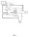
- Fig. 1 shows a diagram of a valve assembly.
- the valve assembly may be incorporated in a mechanical ventilator, for example a blower driven ventilator.
- the blower may, for example, comprise a radial blower, as is known in the art per se.
- the valve assembly may be arranged for being connected with a blower-driven mechanical ventilator.
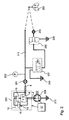
- Fig. 2 shows a diagram of a patient circuit comprising the valve assembly 220 of Fig. 1 .
- similar items have been given the same reference numerals.
- the valve assembly 220 as illustrated in Figs. 1 and 2 , comprises a first conduit 1 for transporting fluid from a blower 209 to an orifice 4.
- This orifice 4 is referred to hereinafter as the first orifice 4.
- the fluid from the blower 209 arrives at an inlet 2 of the conduit 1, as indicated by arrow 3.
- the valve assembly may further comprise a second conduit 5.
- This second conduit may comprise an outlet 6 for forwarding fluid to a patient 203, as indicated by arrow 7.
- the flow from the inlet 2 to the outlet 6 via the first conduit 1 and the second conduit 5 may be controlled by means of a membrane 8 comprising a front side 9 and a back side 10.
- the back side 10 may form at least part of an inner boundary of a cavity 11. By varying the pressure in this cavity 11, the flow may be controlled.
- the front side 9 may face the first orifice 4.
- At least part of the membrane 8 is movable in response to a difference in pressure on the front side 9 and the back side 10 of the membrane 8.
- the membrane 8 may move or deform into a closed position, as illustrated, in which the membrane 8 closes the first orifice 4. In the closed position, the membrane 8 prevents passage of fluid between the first conduit 1 and the second conduit 5.
- the membrane may also move or deform into an open position, in which the first orifice 4 is opened. In the open position, passage of fluid between the first conduit 1 and the second conduit 5 is enabled.
- a bias 18 may be provided, for example in form of a spring, to favor the closed position.
- the bias may also be provided by an elasticity of the membrane in combination with the way in which it is attached in the valve assembly with respect to the border of the first orifice 4 and/or second orifice 14. However, this bias is optional.
- the valve assembly may further comprise a switching circuit 12.
- the switching circuit 12 enables to selectively open and close a fluid connection between the cavity 11 and at least one of:
- the second conduit 5 may comprise a second orifice 14.
- This second orifice 14 may be arranged adjacent the first orifice 4, such that a portion of the front side 9 of the membrane 8 faces the second orifice 14.
- the membrane 8 In the closed position, the membrane 8 may prevent passage of fluid between the first orifice 4 and the second orifice 14. In the open position, the membrane 8 may allow passage of fluid between the first orifice 4 and the second orifice 14.
- the switching circuit 12 comprises a first switch 15 for selectively connecting the cavity 11 with the fluid outlet 6 or a second switch 16.
- the second switch 16 selectively connects the first switch 15 with the fluid inlet 2 or ambient air 13. Consequently, when the first switch 15 connects to the second switch 16, the second switch connects the cavity 11 with the fluid inlet 2 or ambient air 13.
- the valve assembly may comprise a control system 17 for controlling the switching circuit 12.
- the control system 17 may change the connection of the cavity 11 to regulate the flow of gases to and from the patient and/or the blower.
- the control system may further control operation of the blower 209.
- the blower 209 and the switching circuit 12 may also be controlled by separate controllers. Such separate controllers may be synchronized to obtain an effective control of the membrane 8 and the blower 209 during inhalation and exhalation.
- the control system 17 may control the switching circuit in a number of ways to obtain different functionality by means of the valve assembly 220.
- control system 17 may be arranged for connecting the cavity 11 with the fluid outlet 6 during expiration.
- the membrane 8 is kept in the closed position, for example because of the optional bias 18 or because the back side 10 of the membrane 8 is larger than the portion of the front side 9 facing the second orifice 14.
- the control system may further control the blower to generate a suitably low pressure.
- PEEP means positive end-expiratory pressure.
- Positive end-expiratory pressure (PEEP) is a term used in mechanical ventilation to denote the amount of pressure present in the airway at the end of the expiratory cycle. Effectively, this way the membrane 8 may help preventing expired air from reaching the blower (209).
- the membrane 8 may thus act as a check valve during expiration.
- the control system 17 may be arranged for connecting the cavity 11 with ambient air 13 during pressure controlled ventilation.
- the connection with ambient air 13 causes the resistance of the membrane to be reduced. Consequently, it is easier to control the pressure by controlling the pressure generated by the blower.
- the control system 17 may be arranged for connecting the cavity 11 with ambient air 13 or with the fluid outlet 6 during flow controlled ventilation, in dependence on the level of the flow. Controlling the flow generated with a blower is easier when the resistance can be varied.
- One way of varying the resistance of the patient circuit is by connecting the cavity with ambient air 13 or with the fluid outlet 6. The latter causes a larger resistance than the former.
- the control system 17 may be arranged for connecting the cavity 11 with ambient air 13 during flow controlled ventilation for a flow rate above a threshold, and for connecting the cavity 11 with the fluid outlet 6 during flow controlled ventilation for a flow rate below the threshold. At the same time the rotation speed of the blower may be adapted to the resistance to provide the desired flow rate.
- control system 17 may be arranged for realizing a particular flow resistance by oscillating between the connection with the fluid outlet 6 and ambient air 13. By oscillating between these two positions, a pressure in between ambient pressure and fluid outlet pressure may be realized in the cavity. By controlling the relative duration of both connections, a variable resistance may be obtained.
- the control system 17 may comprise an input for receiving an instruction. This input is not shown in the drawing.
- the input may comprise a user interface element on the ventilator. For example, a button may be provided or the instruction may be given by means of a touch screen.
- the input is arranged for receiving an automatically generated signal from a measurement device. Such measurement device may be arranged for providing an alarm signal in suitable cases.
- the control system 17 may be arranged for responding to such automatic signal by changing the settings of the switching circuit and/or the blower, to remove the alarm condition. This way, a fault in the system may be overcome without adverse effect on the patient.
- an instruction to provide inspiratory pressure relief may be received by the control system 17 via the input.
- the control system 17 may be arranged for connecting the cavity with ambient pressure 13, and to lower a blower rotational speed, in response to said instruction. This way, inspiratory pressure is lowered significantly.
- a signal indicative of a blower overpressure, or an instruction to provide blower overpressure relief may be received by the control system 17.
- the control system 17 may be arranged for connecting the cavity 11 with the fluid inlet 2 in response thereto. By providing this connection, the membrane 6 moves into the closed position, therewith removing the pressure caused by the blower.
- the input is arranged for receiving an instruction to perform an occlusion maneuver.
- the control system 17 may be arranged for connecting the cavity 11 with the fluid inlet 2 during the occlusion maneuver. This way, the membrane 8 may be kept in the closed position, in particular when the blower 209 provides sufficient pressure.
- the valve assembly may be implemented as an integral part of a mechanical ventilator comprising a blower 209.
- Fig. 2 illustrates how the valve assembly may be integrated in the ventilator and/or patient circuit.
- a flow sensor 201 and pressure sensor 202 may be provided in between the valve assembly 220 and the patient 203.
- the expiratory circuit may comprise a flow sensor 204, a membrane based valve 205, and a proportional control valve (or switch) 207.
- the membrane based valve 205 When the membrane based valve 205 is open, the expiratory gases may be released into ambient environment 206. When the membrane based valve 205 is closed, expiratory gases may not normally be released, in order to obtain sufficient inspiratory pressure.
- a proportional control valve 207 may be used to connect the back side of the membrane based valve 205 with the inspiratory conduit 211 or with ambient air 208, in order to close or open the membrane based valve 205, respectively.
- a check valve in the inspiratory conduits between the blower 209 and the patient 203 does not need to be in place, because this functionality can be obtained by means of the valve assembly 220, for example using the control system 17.
- a method of operating the valve assembly 220 comprises using the membrane 8 as a check valve during expiration to prevent expired air from reaching the blower 209.
- the method may comprise connecting the cavity 11 with the fluid outlet 6 during expiration, and reducing the blower output pressure to below PEEP level during expiration.
- Another method of operating the valve assembly 220 comprises connecting the cavity 11 with ambient air 13 for reducing the resistance caused by the membrane 8, for example during inspiration.
- control system 17 may be implemented in software as a computer program product. Also other functionality of the control system 17 described herein may be implemented at least partly in software. This software may be executed by a microprocessor of the ventilator. Other ways of implementing the methods and functions are also possible.
- the valve consists of a pneumatic part with a spring loaded membrane and two bistable 3/2 pilot valves. With the pneumatic arrangement as drawn in Fig. 1 , it may be possible to set three pressure levels at the back side 10 of the membrane 8. Either ambient pressure, fluid inlet pressure (pressure generated by the blower 209) or fluid outlet pressure (pressure at the outlet 6 of the valve assembly, towards the patient).
- control valve or switch 16 may be switched to the ambient pressure 13 inlet port and control valve or switch 15 may be switched to the inlet port of control valve or switch 16.
- control valves would remain in this state during expiration, rebreathing might occur. However if control valve or switch 15 is switched to the valve outlet 6 pressure and the blower reduces the pressure to near or below PEEP level, the membrane closes and there rebreathing may be avoided.
- the objective may be to have an appropriate inspiratory resistance for low flow and/or for high flow, as desired.
- the maximum open membrane valve may be used, by connecting the cavity 11 to ambient air 13. Increasing the resistance might reduce the performance and might reduce energy efficiency and/or noise comfort.
- control valve or switch 15 may be set to the outlet 6 pressure of the valve assembly 220. The valve then still opens when the blower pressure is sufficiently high. When going to expiration the valve automatically closes at unchanged control valve settings.
- valve resistance may be decreased by switching control valve or switch 15 back to the inlet pressure of control valve 16, which is set open to ambient.
- control valve 15 may be switched to the outlet of control valve 16 which may be switched to ambient pressure.
- the membrane 8 valve opens.
- control valve 15 may be switched to the outlet of control valve 16 which may be switched to the outlet blower pressure. Because of the arrangement of the membrane 8, for example using appropriate valve ratio and/or a small bias, e.g. a spring load, the membrane closes directly.
- control valve 15 may be switched to the outlet of control valve 16 which may be switched to the outlet blower pressure. This may be done for the prescribed occlusion time (for example, 100 milliseconds).
- control valve may be integrated into a manifold or blower housing.
- the control valves or switches may be mounted directly outside of the manifold (or at another suitable position) and interconnected through tubing (not shown in the drawings).
- Figs. 3 , 4 , and 5 illustrate an example embodiment of the valve assembly as described herein.
- Fig. 3 shows a side view with intersected view of the housing 304.
- Fig. 4 shows an oblique frontal view with intersected view of the housing 304.
- Fig. 5 shows an oblique rear view with intersected view of the housing 304 and membrane valve 303. Similar items have been indicated with the same reference numerals.
- the figures show two switches, in this case piezo valves 301 and 302, a membrane valve 303, and a housing 304.
- the piezo valves may be obtained from Hoerbiger, Germany, for example.
- Membrane valve 303 comprises a membrane 308 with a crater 311 on a front side of the membrane 308 and a cavity 309 on a back side of the membrane 308.
- the membrane 308 may be biased towards the crater 311 (not shown).
- First conduit 305, 310 may be connected to the blower output (not shown).
- the first conduit 305 extends at 310 in the crater 311 so that air 3 from the blower reaches the membrane 308.
- Arrow 3 indicates the direction of flow from the blower into the first conduit 305, 310.
- Second conduit 306 has an outlet 6 (sketched as a dashed circle) to enable air to leave the conduit 306 in the direction of arrow 7.
- a patient hose may be connectable to the second conduit 306 to transport the air to a patient (not shown).
- Piezo valve 301 is connected to the cavity 309 on the back side of the membrane 308 via conduit 307. Depending on the position of piezo valve 301, the cavity is connected with the second conduit 306 or, via conduit 312, with piezo valve 302.
- Piezo valve 302 may, depending on its position, connect the outlet of the piezo valve 301 with either of ambient air or the first conduit 305.
Landscapes
- Health & Medical Sciences (AREA)
- Heart & Thoracic Surgery (AREA)
- Life Sciences & Earth Sciences (AREA)
- Engineering & Computer Science (AREA)
- Anesthesiology (AREA)
- Biomedical Technology (AREA)
- Emergency Medicine (AREA)
- Hematology (AREA)
- Pulmonology (AREA)
- Animal Behavior & Ethology (AREA)
- General Health & Medical Sciences (AREA)
- Public Health (AREA)
- Veterinary Medicine (AREA)
- Infusion, Injection, And Reservoir Apparatuses (AREA)
- Safety Valves (AREA)
Description
- The invention relates to a valve assembly for a blower driven ventilator. The invention further relates to a control system and method for controlling a valve assembly during a ventilation operation of a blower.
- In a mechanical ventilator for providing ventilatory assistance to a patient, different kinds of sources may be used for providing an inspiratory gas mixture to the patient. For example, pressurized air and/or oxygen can be used. Alternatively, a blower can be used. Unlike a pressurized air or oxygen source, the blower has a low pneumatic impedance or resistance when the flow delivery is interrupted. This may typically happen during the patient's expiration. The consequence of the low impedance is that backflow into the ventilator can occur, which can result in rebreathing and airway plateau-pressure drop. The traditional solution to this problem is to design a check-valve (or non-return valve) into the pneumatic system.
- In existing systems, controlling the flow generated with a radial blower is difficult, for example it is difficult to control flow for low flow settings, for example for restrictive patients, small children, or any other low compliance patients, or for obstructive patients with high airway resistance. Radial blowers tend to behave oscillatory in case the flow level is controlled, because they may behave as ideal pressure sources at low flow situations. Traditionally this problem is addressed by adding a control valve that acts like a variable resistance, with the radial blower at an almost fixed pressure setting. However, such a valve is rather big because the flow-resistance can not be too high relative to the maximum achievable blower pressure. And the power consumption of the blower increases together with the thermal load and noise production.
-
US 6,772,359 B2 discloses a system with a pneumatic membrane inhalation valve. The front side of the membrane faces an orifice of the airway; the back side can be fluidly connected, via a selector-valve, with either the blower output or the inspiratory conduit, which is connected to the patient via a check-valve. The check-valve is used to prevent reflow of expiration gases into the blower. That document also discloses a rotary directional-control valve which allows the transmission of the gas stream to be varied by rotating a spool to close or open a passage through an oblong opening. -
U.S. 2002/014239 A1 discloses a valve assembly comprising the features of the preamble ofclaim 1. -
FR 2 887 776 A1 - It would be advantageous to have an improved valve assembly for a blower driven ventilator which allows to reduce or increase the resistance caused by the membrane to allow a more accurate control. This object is solved by a valve assembly as defined in
claim 1. Preferred embodiments are set out in the dependent claims. - To better address this concern, a first aspect of the invention provides a valve assembly comprising a first conduit comprising an inlet for receiving fluid from the blower and a first orifice; a second conduit comprising an outlet for forwarding fluid to a patient; a membrane comprising a front side and a back side, wherein the back side forms at least part of a boundary of a cavity, and wherein the front side faces the first orifice, and wherein at least part of the membrane is movable in response to a difference in pressure on the front side and the back side of the membrane between a closed position in which the membrane prevents passage of fluid between the first conduit and the second conduit and an open position in which the membrane allows passage of fluid between the first conduit and the second conduit; and a switching circuit for enabling to selectively open and close a fluid connection between the cavity and the blower via the fluid inlet, a fluid connection between the cavity and the patient via the fluid outlet, and a fluid connection between the cavity and ambient air.
- The valve assembly comprises a control system for controlling the switching circuit during a ventilation operation of the blower. This allows the valve assembly to be given more functionality by setting the switching circuit according to the desired functionality.
- Because the cavity can be connected with ambient air, the pressure on the back side can be considerably lowered. This way, the resistance in the circuit is reduced, which allows reducing the pressure drop at the membrane at a higher flow level of gases towards the patient. Moreover, the noise, caused by the blower, may be reduced. Moreover, the energy consumption needed to realize a particular flow level towards the patient may be reduced. The valve may be relatively small compared to a rotary directional-control valve, and still the resistance of the valve may be varied by means of the switching circuit.
- Moreover, in case the expiration tubing or valve is obstructed, the patient system can be depressurized by connecting the cavity with ambient air, which enables the expiration gases to flow in the direction of the blower, therewith providing inspiratory pressure relief. Blower overpressure relief may be provided by closing the membrane by connecting the cavity with the fluid inlet. Moreover, the valve assembly may act as a check valve by connecting the cavity with the fluid outlet. The valve assembly may further be used as a variable fluid resistor by connecting it selectively with ambient air or with the fluid outlet. Moreover, by connecting the membrane with the fluid inlet, the flow of fluid from the ventilator to the patient may be stopped altogether. Combining some or all of these functionalities in a single membrane based valve assembly reduces cost and improves efficiency.
- The switching circuit may comprise a first switch for selectively connecting the cavity with the fluid outlet or a second switch, and the second switch for selectively connecting the first switch with the fluid inlet or ambient air. This is an efficient implementation of the switching circuit. It allows rapid switching between the fluid inlet and ambient air. Moreover it allows rapid switching to and from the connection with the fluid outlet.
- The control system may be arranged for connecting the cavity with the fluid outlet during expiration. This way, the membrane will move towards the closed position when expiration pressure is applied. The membrane may act as a check valve during expiration to prevent expired air from reaching the blower.
- The control system may be arranged for reducing the blower output pressure to below PEEP level during expiration. This supports the check valve functionality of the valve assembly.
- The control system may be arranged for connecting the cavity with ambient air during pressure controlled ventilation. This setting reduces the resistance caused by the membrane.
- The control system may be arranged for connecting the cavity with ambient air or with the fluid outlet during flow controlled ventilation, in dependence on the level of the flow. This allows reducing or increasing the resistance caused by the membrane, which allows the flow to be controlled more accurately. At least some of the problems associated with flow-controlled ventilation may be overcome by varying the resistance using the valve assembly as described herein. Moreover, the blower rotational speed may also be varied in addition to the resistance, to obtain a given flow level.
- The control system may be arranged for connecting the cavity with ambient air during flow controlled ventilation for a flow rate above a threshold, and for connecting the cavity with the fluid outlet during flow controlled ventilation for a flow rate below the threshold. This way, for a relatively high volume level, the resistance may be reduced, whereas for a lower volume level, the resistance may be increased.
- The control system may be arranged for realizing a particular flow resistance by oscillating between the connection with the fluid outlet and ambient air. By quickly switching between fluid outlet and ambient air, the resistance can be set to a level in between the level corresponding to the connection with fluid outlet and the level corresponding to the connection with ambient air. By adjusting the relative duration of either connection compared to the other, the resistance can be fine-tuned. This allows controlling the flow level with greater accuracy.
- The control system may comprise an input for receiving an instruction to provide inspiratory pressure relief, wherein the control system is arranged for connecting the cavity with ambient pressure, and to lower the blower rotational speed, in response to said instruction. By the connection with ambient pressure, while the blower is producing only low or no pressure, the patient can easily exhale, because the air is guided from the patient through the valve towards the blower. The control system may be arranged for setting the blower rotational speed to zero or close to zero.
- The control system may comprise an input for receiving a signal indicative of a blower overpressure, and wherein the control system is arranged for connecting the cavity with the fluid inlet when blower overpressure is detected. This connection causes the membrane to move towards the closed position. Consequently, the blower pressure is blocked from the patient, so the blower overpressure is stopped.
- The control system may comprise an input for receiving an instruction to perform an occlusion maneuver, and wherein the control system is arranged for connecting the cavity with the fluid inlet during the occlusion maneuver. This connection causes the membrane to move to the closed position, causing that the patient cannot breathe.
- Another aspect of the invention provides a method of operating the valve assembly set forth, comprising using the membrane as a check valve during expiration to prevent expired air from reaching the blower, by connecting the cavity with the fluid outlet during expiration, and reducing the blower output pressure to below PEEP level during expiration.
- Another aspect of the invention provides a method of operating the valve assembly set forth, comprising operating the switching circuit to connect the cavity with ambient air during ventilation, in particular during mandatory inhalation.
- It will be appreciated by those skilled in the art that two or more of the above-mentioned embodiments, implementations, and/or aspects of the invention may be combined in any way deemed useful.
- These and other aspects of the invention are apparent from and will be elucidated with reference to the embodiments described hereinafter. In the drawings,
-
Fig. 1 shows a diagram of a valve assembly for a blower driven ventilator; -
Fig. 2 shows a diagram of a patient circuit with a blower; -
Fig. 3 shows a side view of a valve assembly; -
Fig. 4 shows an oblique view of front side of a valve assembly; and -
Fig. 5 shows an oblique view of a back side of a valve assembly. - It is noted that the embodiments described in the following are merely examples. Modifications of these examples may be made by the person skilled in the art.
-
Fig. 1 shows a diagram of a valve assembly. The valve assembly may be incorporated in a mechanical ventilator, for example a blower driven ventilator. The blower may, for example, comprise a radial blower, as is known in the art per se. Alternatively, the valve assembly may be arranged for being connected with a blower-driven mechanical ventilator.Fig. 2 shows a diagram of a patient circuit comprising thevalve assembly 220 ofFig. 1 . In the figures, similar items have been given the same reference numerals. - The
valve assembly 220, as illustrated inFigs. 1 and2 , comprises afirst conduit 1 for transporting fluid from ablower 209 to an orifice 4. This orifice 4 is referred to hereinafter as the first orifice 4. The fluid from theblower 209 arrives at an inlet 2 of theconduit 1, as indicated byarrow 3. - The valve assembly may further comprise a second conduit 5. This second conduit may comprise an
outlet 6 for forwarding fluid to apatient 203, as indicated byarrow 7. - The flow from the inlet 2 to the
outlet 6 via thefirst conduit 1 and the second conduit 5 may be controlled by means of a membrane 8 comprising a front side 9 and aback side 10. Theback side 10 may form at least part of an inner boundary of acavity 11. By varying the pressure in thiscavity 11, the flow may be controlled. The front side 9 may face the first orifice 4. At least part of the membrane 8 is movable in response to a difference in pressure on the front side 9 and theback side 10 of the membrane 8. The membrane 8 may move or deform into a closed position, as illustrated, in which the membrane 8 closes the first orifice 4. In the closed position, the membrane 8 prevents passage of fluid between thefirst conduit 1 and the second conduit 5. The membrane may also move or deform into an open position, in which the first orifice 4 is opened. In the open position, passage of fluid between thefirst conduit 1 and the second conduit 5 is enabled. Abias 18 may be provided, for example in form of a spring, to favor the closed position. The bias may also be provided by an elasticity of the membrane in combination with the way in which it is attached in the valve assembly with respect to the border of the first orifice 4 and/orsecond orifice 14. However, this bias is optional. - The valve assembly may further comprise a
switching circuit 12. The switchingcircuit 12 enables to selectively open and close a fluid connection between thecavity 11 and at least one of: - the
blower 209. This fluid connection may be realized via thefirst conduit 1 and the fluid inlet 2; - the
patient 203. This fluid connection may be realized via the second conduit 5 and thefluid outlet 6; and -
ambient air 13. - The second conduit 5 may comprise a
second orifice 14. Thissecond orifice 14 may be arranged adjacent the first orifice 4, such that a portion of the front side 9 of the membrane 8 faces thesecond orifice 14. In the closed position, the membrane 8 may prevent passage of fluid between the first orifice 4 and thesecond orifice 14. In the open position, the membrane 8 may allow passage of fluid between the first orifice 4 and thesecond orifice 14. - The figures show an example implementation of the switching circuit using two switches. However, this is only an example. Another implementation could use a single switch having three positions, for example. In the example implementation, the switching
circuit 12 comprises afirst switch 15 for selectively connecting thecavity 11 with thefluid outlet 6 or asecond switch 16. Thesecond switch 16 selectively connects thefirst switch 15 with the fluid inlet 2 orambient air 13. Consequently, when thefirst switch 15 connects to thesecond switch 16, the second switch connects thecavity 11 with the fluid inlet 2 orambient air 13. - The valve assembly may comprise a
control system 17 for controlling the switchingcircuit 12. During a ventilation operation of theblower 209, thecontrol system 17 may change the connection of thecavity 11 to regulate the flow of gases to and from the patient and/or the blower. The control system may further control operation of theblower 209. However, theblower 209 and the switchingcircuit 12 may also be controlled by separate controllers. Such separate controllers may be synchronized to obtain an effective control of the membrane 8 and theblower 209 during inhalation and exhalation. - The
control system 17 may control the switching circuit in a number of ways to obtain different functionality by means of thevalve assembly 220. - For example, the
control system 17 may be arranged for connecting thecavity 11 with thefluid outlet 6 during expiration. This way, the membrane 8 is kept in the closed position, for example because of theoptional bias 18 or because theback side 10 of the membrane 8 is larger than the portion of the front side 9 facing thesecond orifice 14. The control system may further control the blower to generate a suitably low pressure. For example, by reducing the blower output pressure to below PEEP level during expiration. Herein, PEEP means positive end-expiratory pressure. Positive end-expiratory pressure (PEEP) is a term used in mechanical ventilation to denote the amount of pressure present in the airway at the end of the expiratory cycle. Effectively, this way the membrane 8 may help preventing expired air from reaching the blower (209). The membrane 8 may thus act as a check valve during expiration. - The
control system 17 may be arranged for connecting thecavity 11 withambient air 13 during pressure controlled ventilation. The connection withambient air 13 causes the resistance of the membrane to be reduced. Consequently, it is easier to control the pressure by controlling the pressure generated by the blower. - The
control system 17 may be arranged for connecting thecavity 11 withambient air 13 or with thefluid outlet 6 during flow controlled ventilation, in dependence on the level of the flow. Controlling the flow generated with a blower is easier when the resistance can be varied. One way of varying the resistance of the patient circuit is by connecting the cavity withambient air 13 or with thefluid outlet 6. The latter causes a larger resistance than the former. For example, thecontrol system 17 may be arranged for connecting thecavity 11 withambient air 13 during flow controlled ventilation for a flow rate above a threshold, and for connecting thecavity 11 with thefluid outlet 6 during flow controlled ventilation for a flow rate below the threshold. At the same time the rotation speed of the blower may be adapted to the resistance to provide the desired flow rate. - Alternatively, the
control system 17 may be arranged for realizing a particular flow resistance by oscillating between the connection with thefluid outlet 6 andambient air 13. By oscillating between these two positions, a pressure in between ambient pressure and fluid outlet pressure may be realized in the cavity. By controlling the relative duration of both connections, a variable resistance may be obtained. - The
control system 17 may comprise an input for receiving an instruction. This input is not shown in the drawing. The input may comprise a user interface element on the ventilator. For example, a button may be provided or the instruction may be given by means of a touch screen. Alternatively, the input is arranged for receiving an automatically generated signal from a measurement device. Such measurement device may be arranged for providing an alarm signal in suitable cases. Thecontrol system 17 may be arranged for responding to such automatic signal by changing the settings of the switching circuit and/or the blower, to remove the alarm condition. This way, a fault in the system may be overcome without adverse effect on the patient. - For example, an instruction to provide inspiratory pressure relief may be received by the
control system 17 via the input. Thecontrol system 17 may be arranged for connecting the cavity withambient pressure 13, and to lower a blower rotational speed, in response to said instruction. This way, inspiratory pressure is lowered significantly. - In another example, a signal indicative of a blower overpressure, or an instruction to provide blower overpressure relief, may be received by the
control system 17. Thecontrol system 17 may be arranged for connecting thecavity 11 with the fluid inlet 2 in response thereto. By providing this connection, themembrane 6 moves into the closed position, therewith removing the pressure caused by the blower. - In another example, the input is arranged for receiving an instruction to perform an occlusion maneuver. In response to said instruction, the
control system 17 may be arranged for connecting thecavity 11 with the fluid inlet 2 during the occlusion maneuver. This way, the membrane 8 may be kept in the closed position, in particular when theblower 209 provides sufficient pressure. - The valve assembly may be implemented as an integral part of a mechanical ventilator comprising a
blower 209. -
Fig. 2 illustrates how the valve assembly may be integrated in the ventilator and/or patient circuit. Aflow sensor 201 andpressure sensor 202 may be provided in between thevalve assembly 220 and thepatient 203. The expiratory circuit may comprise aflow sensor 204, a membrane basedvalve 205, and a proportional control valve (or switch) 207. When the membrane basedvalve 205 is open, the expiratory gases may be released intoambient environment 206. When the membrane basedvalve 205 is closed, expiratory gases may not normally be released, in order to obtain sufficient inspiratory pressure. Aproportional control valve 207 may be used to connect the back side of the membrane basedvalve 205 with theinspiratory conduit 211 or withambient air 208, in order to close or open the membrane basedvalve 205, respectively. - It is noted that a check valve in the inspiratory conduits between the
blower 209 and thepatient 203 does not need to be in place, because this functionality can be obtained by means of thevalve assembly 220, for example using thecontrol system 17. - A method of operating the
valve assembly 220, for example bycontrol system 17, comprises using the membrane 8 as a check valve during expiration to prevent expired air from reaching theblower 209. The method may comprise connecting thecavity 11 with thefluid outlet 6 during expiration, and reducing the blower output pressure to below PEEP level during expiration. - Another method of operating the
valve assembly 220 comprises connecting thecavity 11 withambient air 13 for reducing the resistance caused by the membrane 8, for example during inspiration. - These methods may be implemented in software as a computer program product. Also other functionality of the
control system 17 described herein may be implemented at least partly in software. This software may be executed by a microprocessor of the ventilator. Other ways of implementing the methods and functions are also possible. - In an embodiment, the valve consists of a pneumatic part with a spring loaded membrane and two bistable 3/2 pilot valves. With the pneumatic arrangement as drawn in
Fig. 1 , it may be possible to set three pressure levels at theback side 10 of the membrane 8. Either ambient pressure, fluid inlet pressure (pressure generated by the blower 209) or fluid outlet pressure (pressure at theoutlet 6 of the valve assembly, towards the patient). - In case of pressure controlled ventilation, it may be advantageous to have a low inspiratory resistance. The membrane 8 may be made to have the maximum clearance relative to the first orifice 4, drawn as a crater in the figure. The membrane can be lifted to the maximum by setting the backpressure to ambient pressure. The blower pressure may easily lift the membrane. To this end, control valve or switch 16 may be switched to the
ambient pressure 13 inlet port and control valve or switch 15 may be switched to the inlet port of control valve orswitch 16. - If the control valves would remain in this state during expiration, rebreathing might occur. However if control valve or switch 15 is switched to the
valve outlet 6 pressure and the blower reduces the pressure to near or below PEEP level, the membrane closes and there rebreathing may be avoided. - In case of flow controlled ventilation, the objective may be to have an appropriate inspiratory resistance for low flow and/or for high flow, as desired. For higher flow levels, the maximum open membrane valve may be used, by connecting the
cavity 11 toambient air 13. Increasing the resistance might reduce the performance and might reduce energy efficiency and/or noise comfort. To increase the resistance of the valve (for lower flow levels), control valve or switch 15 may be set to theoutlet 6 pressure of thevalve assembly 220. The valve then still opens when the blower pressure is sufficiently high. When going to expiration the valve automatically closes at unchanged control valve settings. - At higher flow values this increased resistance may be less desirable. Therefore, above a specific flow level, the valve resistance may be decreased by switching control valve or switch 15 back to the inlet pressure of
control valve 16, which is set open to ambient. - This covers a number of normal ventilation modes. The system may also be used to overcome several fault conditions. For example, to provide inspiratory pressure relief,
control valve 15 may be switched to the outlet ofcontrol valve 16 which may be switched to ambient pressure. The membrane 8 valve opens. To provide blower overpressure relief,control valve 15 may be switched to the outlet ofcontrol valve 16 which may be switched to the outlet blower pressure. Because of the arrangement of the membrane 8, for example using appropriate valve ratio and/or a small bias, e.g. a spring load, the membrane closes directly. - The system may also be used to perform an occlusion maneuver. In this case,
control valve 15 may be switched to the outlet ofcontrol valve 16 which may be switched to the outlet blower pressure. This may be done for the prescribed occlusion time (for example, 100 milliseconds). - In an embodiment, the control valve may be integrated into a manifold or blower housing. The control valves or switches may be mounted directly outside of the manifold (or at another suitable position) and interconnected through tubing (not shown in the drawings).
-
Figs. 3 ,4 , and5 illustrate an example embodiment of the valve assembly as described herein.Fig. 3 shows a side view with intersected view of thehousing 304.Fig. 4 shows an oblique frontal view with intersected view of thehousing 304.Fig. 5 shows an oblique rear view with intersected view of thehousing 304 andmembrane valve 303. Similar items have been indicated with the same reference numerals. The figures show two switches, in this casepiezo valves membrane valve 303, and ahousing 304. The piezo valves may be obtained from Hoerbiger, Germany, for example.Membrane valve 303 comprises amembrane 308 with acrater 311 on a front side of themembrane 308 and acavity 309 on a back side of themembrane 308. Themembrane 308 may be biased towards the crater 311 (not shown).First conduit first conduit 305 extends at 310 in thecrater 311 so thatair 3 from the blower reaches themembrane 308.Arrow 3 indicates the direction of flow from the blower into thefirst conduit Second conduit 306 has an outlet 6 (sketched as a dashed circle) to enable air to leave theconduit 306 in the direction ofarrow 7. A patient hose may be connectable to thesecond conduit 306 to transport the air to a patient (not shown).Piezo valve 301 is connected to thecavity 309 on the back side of themembrane 308 viaconduit 307. Depending on the position ofpiezo valve 301, the cavity is connected with thesecond conduit 306 or, viaconduit 312, withpiezo valve 302.Piezo valve 302 may, depending on its position, connect the outlet of thepiezo valve 301 with either of ambient air or thefirst conduit 305. - It should be noted that the above-mentioned embodiments illustrate rather than limit the invention, and that those skilled in the art will be able to design many alternative embodiments without departing from the scope of the appended claims. In the claims, any reference signs placed between parentheses shall not be construed as limiting the claim. Use of the verb "comprise" and its conjugations does not exclude the presence of elements or steps other than those stated in a claim. The article "a" or "an" preceding an element does not exclude the presence of a plurality of such elements. The invention may be implemented by means of hardware comprising several distinct elements, and by means of a suitably programmed computer. In the device claim enumerating several means, several of these means may be embodied by one and the same item of hardware. The mere fact that certain measures are recited in mutually different dependent claims does not indicate that a combination of these measures cannot be used to advantage.
Claims (13)
- A valve assembly for a blower driven ventilator, comprising
a first conduit (1) comprising an inlet (2) for receiving fluid from the blower (209) and a first orifice (4);
a second conduit (5) comprising an outlet (6) for forwarding fluid to a patient (203);
a membrane (8) comprising a front side (9) and a back side (10), wherein the back side (10) forms at least part of a boundary of a cavity (11), and wherein the front side (9) faces the first orifice (4), and wherein at least part of the membrane (8) is movable in response to a difference in pressure on the front side (9) and the back side (10) of the membrane (8) between a closed position in which the membrane (8) prevents passage of a fluid between the first conduit (1) and the second conduit (5) and an open position in which the membrane (8) allows passage of fluid between the first conduit (1) and the second conduit (5) ; and
a switching circuit (12) for enabling to selectively open and close a fluid connection between the cavity (11) and the blower (209) via the fluid inlet (2), and a fluid connection between the cavity (11) and the patient (203) via the fluid outlet (6), characterized in that the switching circuit (12) is further arranged for enabling to selectively open and close a fluid connection between the cavity (11) and ambient air (13). - The valve assembly according to claim 1, further comprising a control system (17) for controlling the switching circuit (12) during a ventilation operation of the blower (209).
- The valve assembly according to claim 2, wherein the control system (17) is able to connect the cavity (11) with the fluid outlet (6) during expiration.
- The valve assembly according to claim 3, wherein the control system (17) is arranged for reducing a blower output pressure to below PEEP level during expiration.
- The valve assembly according to claim 4, wherein the membrane (8) is a check valve during expiration to prevent expired air from reaching the blower (209).
- The valve assembly according to claim 2, wherein the control system (17) connects the cavity (11) with ambient air during pressure controlled ventilation.
- The valve assembly according to claim 2, wherein the control system (17) connects the cavity (11) with ambient air (13) or with the fluid outlet (6) during flow controlled ventilation, in dependence on the level of the flow.
- The valve assembly according to claim 7, wherein the control system (17) connects the cavity (11) with ambient air (13) during flow controlled ventilation for a flow rate above a threshold, and connects the cavity (11) with the fluid outlet (6) during flow controlled ventilation for a flow rate below the threshold.
- The valve assembly according to claim 7, wherein the control system (17) realizes a particular flow resistance by oscillating between the connecting with the fluid outlet (6) and ambient air (13).
- The valve assembly according to claim 2, wherein the control system (17) comprises an input for receiving an instruction to provide inspiratory pressure relieve, and wherein the control system (17) connects the cavity with ambient pressure (13), and to lower a blower rotational speed, in response to said instruction.
- The valve assembly according to claim 2, wherein the control system (17) comprises an input for receiving a signal indicative of a blower overpressure, and wherein the control system (17) connects the cavity (11) with the fluid inlet (2) when blower overpressure is detected.
- The valve assembly according to claim 2, wherein the control system (17) comprises an input for receiving an instruction to perform an occlusion maneuver, and wherein the control system (17) connects the cavity (11) with the fluid inlet (2) during the occlusion maneuver.
- A mechanical ventilator comprising a blower (209) and a valve assembly according of any of the preceding claims.
Priority Applications (2)
| Application Number | Priority Date | Filing Date | Title |
|---|---|---|---|
| EP10158003.3A EP2368592B1 (en) | 2010-03-26 | 2010-03-26 | Combi-valve for a blower driven ventilator |
| US13/071,891 US9616191B2 (en) | 2010-03-26 | 2011-03-25 | Combi-valve for a blower driven ventilator |
Applications Claiming Priority (1)
| Application Number | Priority Date | Filing Date | Title |
|---|---|---|---|
| EP10158003.3A EP2368592B1 (en) | 2010-03-26 | 2010-03-26 | Combi-valve for a blower driven ventilator |
Publications (2)
| Publication Number | Publication Date |
|---|---|
| EP2368592A1 EP2368592A1 (en) | 2011-09-28 |
| EP2368592B1 true EP2368592B1 (en) | 2013-04-24 |
Family
ID=42312837
Family Applications (1)
| Application Number | Title | Priority Date | Filing Date |
|---|---|---|---|
| EP10158003.3A Not-in-force EP2368592B1 (en) | 2010-03-26 | 2010-03-26 | Combi-valve for a blower driven ventilator |
Country Status (2)
| Country | Link |
|---|---|
| US (1) | US9616191B2 (en) |
| EP (1) | EP2368592B1 (en) |
Families Citing this family (11)
| Publication number | Priority date | Publication date | Assignee | Title |
|---|---|---|---|---|
| DE102012010525A1 (en) * | 2011-07-02 | 2013-01-03 | Dräger Medical GmbH | Method for functional control of a ventilation system |
| US20130167843A1 (en) * | 2011-12-31 | 2013-07-04 | Nellcor Puritan Bennett Llc | Piezoelectric blower piloted valve |
| EP3062859B1 (en) | 2013-10-30 | 2022-07-06 | ResMed Pty Ltd | Control for pressure of a patient interface |
| FR3040886A1 (en) * | 2015-09-10 | 2017-03-17 | Air Liquide Medical Systems | SAFETY SYSTEM FOR MEDICAL FAN |
| CN109069778B (en) | 2016-02-29 | 2022-06-10 | 伊诺维科技医疗解决方案有限公司 | Portable light breathing machine system |
| DE102017009602A1 (en) * | 2017-10-13 | 2019-04-18 | Drägerwerk AG & Co. KGaA | Method and device for ventilating a patient |
| DE202017005964U1 (en) | 2017-11-17 | 2017-12-14 | Drägerwerk AG & Co. KGaA | Check valve for a compact ventilation system and compact ventilation system |
| DE102019003607B4 (en) * | 2019-05-23 | 2022-01-13 | Drägerwerk AG & Co. KGaA | Valve assembly for a ventilator |
| TWI703995B (en) * | 2019-07-19 | 2020-09-11 | 台灣基督長老教會馬偕醫療財團法人馬偕紀念醫院 | Portable ventilator and methods for providing oscillatory flow |
| DE102020000335A1 (en) * | 2020-01-21 | 2021-07-22 | Drägerwerk AG & Co. KGaA | Valve arrangement with shut-off unit and procedure for a ventilator |
| CN114146282B (en) * | 2021-12-08 | 2022-12-09 | 山东大学 | End-expiratory positive pressure valve for portable respirator and control method thereof |
Family Cites Families (8)
| Publication number | Priority date | Publication date | Assignee | Title |
|---|---|---|---|---|
| US3375839A (en) * | 1965-11-12 | 1968-04-02 | William F. Crenshaw | Breathing oxygen mask inhalation and exhalation diaphragm valve unit |
| US5002050A (en) * | 1986-09-17 | 1991-03-26 | Mcginnis Gerald E | Medical gas flow control valve, system and method |
| KR100336573B1 (en) | 1999-11-30 | 2002-05-16 | 박종섭 | Rambus DRAM |
| FR2812203B1 (en) * | 2000-07-31 | 2003-01-03 | Saime Sarl | APPARATUS FOR AIDING THE VENTILATION OF A PATIENT |
| JP3726886B2 (en) * | 2001-06-29 | 2005-12-14 | 興研株式会社 | Breathing apparatus |
| FR2887776B1 (en) * | 2005-06-29 | 2008-04-04 | Taema Sa | VENTILATION APPARATUS |
| US20070251527A1 (en) * | 2006-04-21 | 2007-11-01 | Tiara Medical Systems, Inc. | Self-contained respiratory therapy apparatus for enhanced patient compliance and therapeutic efficacy |
| US8020558B2 (en) * | 2007-01-26 | 2011-09-20 | Cs Medical, Inc. | System for providing flow-targeted ventilation synchronized to a patient's breathing cycle |
-
2010
- 2010-03-26 EP EP10158003.3A patent/EP2368592B1/en not_active Not-in-force
-
2011
- 2011-03-25 US US13/071,891 patent/US9616191B2/en not_active Expired - Fee Related
Also Published As
| Publication number | Publication date |
|---|---|
| US20110232640A1 (en) | 2011-09-29 |
| EP2368592A1 (en) | 2011-09-28 |
| US9616191B2 (en) | 2017-04-11 |
Similar Documents
| Publication | Publication Date | Title |
|---|---|---|
| US9616191B2 (en) | Combi-valve for a blower driven ventilator | |
| US11717637B2 (en) | Breathable gas inlet control device for respiratory treatment apparatus | |
| US20220265943A1 (en) | Portable light-weight ventilator system | |
| US7617824B2 (en) | Ventilator adaptable for use with either a dual-limb circuit or a single-limb circuit | |
| JP3502349B2 (en) | Ventilator system | |
| EP0548624B1 (en) | Medical ventilator | |
| CN106492321B (en) | A kind of ventilator | |
| WO2007102866A2 (en) | Ventilator adaptable for use with either a dual-limb or a single-limb circuit | |
| RU2550661C2 (en) | System and method for controlling leak from contour, delivering to subject suitable for breathing gas flow under pressure | |
| US11141551B2 (en) | Ventilation drive for an anesthesia device and method for operating such a ventilation drive | |
| CN114225179A (en) | Safety Pressure Relief Devices and Ventilators | |
| CN217041020U (en) | Safe pressure relief device and breathing machine | |
| JP3802099B2 (en) | Ventilator | |
| JPH02209157A (en) | Artificial respirator | |
| JPH049545B2 (en) |
Legal Events
| Date | Code | Title | Description |
|---|---|---|---|
| PUAI | Public reference made under article 153(3) epc to a published international application that has entered the european phase |
Free format text: ORIGINAL CODE: 0009012 |
|
| AK | Designated contracting states |
Kind code of ref document: A1 Designated state(s): AT BE BG CH CY CZ DE DK EE ES FI FR GB GR HR HU IE IS IT LI LT LU LV MC MK MT NL NO PL PT RO SE SI SK SM TR |
|
| AX | Request for extension of the european patent |
Extension state: AL BA ME RS |
|
| 17P | Request for examination filed |
Effective date: 20120322 |
|
| 17Q | First examination report despatched |
Effective date: 20120504 |
|
| GRAP | Despatch of communication of intention to grant a patent |
Free format text: ORIGINAL CODE: EPIDOSNIGR1 |
|
| GRAS | Grant fee paid |
Free format text: ORIGINAL CODE: EPIDOSNIGR3 |
|
| GRAA | (expected) grant |
Free format text: ORIGINAL CODE: 0009210 |
|
| AK | Designated contracting states |
Kind code of ref document: B1 Designated state(s): AT BE BG CH CY CZ DE DK EE ES FI FR GB GR HR HU IE IS IT LI LT LU LV MC MK MT NL NO PL PT RO SE SI SK SM TR |
|
| REG | Reference to a national code |
Ref country code: GB Ref legal event code: FG4D |
|
| REG | Reference to a national code |
Ref country code: CH Ref legal event code: EP |
|
| REG | Reference to a national code |
Ref country code: AT Ref legal event code: REF Ref document number: 608216 Country of ref document: AT Kind code of ref document: T Effective date: 20130515 |
|
| REG | Reference to a national code |
Ref country code: IE Ref legal event code: FG4D |
|
| REG | Reference to a national code |
Ref country code: DE Ref legal event code: R096 Ref document number: 602010006491 Country of ref document: DE Effective date: 20130620 |
|
| REG | Reference to a national code |
Ref country code: NL Ref legal event code: T3 |
|
| REG | Reference to a national code |
Ref country code: AT Ref legal event code: MK05 Ref document number: 608216 Country of ref document: AT Kind code of ref document: T Effective date: 20130424 |
|
| REG | Reference to a national code |
Ref country code: LT Ref legal event code: MG4D |
|
| PG25 | Lapsed in a contracting state [announced via postgrant information from national office to epo] |
Ref country code: AT Free format text: LAPSE BECAUSE OF FAILURE TO SUBMIT A TRANSLATION OF THE DESCRIPTION OR TO PAY THE FEE WITHIN THE PRESCRIBED TIME-LIMIT Effective date: 20130424 Ref country code: LT Free format text: LAPSE BECAUSE OF FAILURE TO SUBMIT A TRANSLATION OF THE DESCRIPTION OR TO PAY THE FEE WITHIN THE PRESCRIBED TIME-LIMIT Effective date: 20130424 Ref country code: SI Free format text: LAPSE BECAUSE OF FAILURE TO SUBMIT A TRANSLATION OF THE DESCRIPTION OR TO PAY THE FEE WITHIN THE PRESCRIBED TIME-LIMIT Effective date: 20130424 Ref country code: BE Free format text: LAPSE BECAUSE OF FAILURE TO SUBMIT A TRANSLATION OF THE DESCRIPTION OR TO PAY THE FEE WITHIN THE PRESCRIBED TIME-LIMIT Effective date: 20130424 Ref country code: IS Free format text: LAPSE BECAUSE OF FAILURE TO SUBMIT A TRANSLATION OF THE DESCRIPTION OR TO PAY THE FEE WITHIN THE PRESCRIBED TIME-LIMIT Effective date: 20130824 Ref country code: PT Free format text: LAPSE BECAUSE OF FAILURE TO SUBMIT A TRANSLATION OF THE DESCRIPTION OR TO PAY THE FEE WITHIN THE PRESCRIBED TIME-LIMIT Effective date: 20130826 Ref country code: ES Free format text: LAPSE BECAUSE OF FAILURE TO SUBMIT A TRANSLATION OF THE DESCRIPTION OR TO PAY THE FEE WITHIN THE PRESCRIBED TIME-LIMIT Effective date: 20130804 Ref country code: GR Free format text: LAPSE BECAUSE OF FAILURE TO SUBMIT A TRANSLATION OF THE DESCRIPTION OR TO PAY THE FEE WITHIN THE PRESCRIBED TIME-LIMIT Effective date: 20130725 Ref country code: SE Free format text: LAPSE BECAUSE OF FAILURE TO SUBMIT A TRANSLATION OF THE DESCRIPTION OR TO PAY THE FEE WITHIN THE PRESCRIBED TIME-LIMIT Effective date: 20130424 Ref country code: FI Free format text: LAPSE BECAUSE OF FAILURE TO SUBMIT A TRANSLATION OF THE DESCRIPTION OR TO PAY THE FEE WITHIN THE PRESCRIBED TIME-LIMIT Effective date: 20130424 Ref country code: NO Free format text: LAPSE BECAUSE OF FAILURE TO SUBMIT A TRANSLATION OF THE DESCRIPTION OR TO PAY THE FEE WITHIN THE PRESCRIBED TIME-LIMIT Effective date: 20130724 |
|
| PG25 | Lapsed in a contracting state [announced via postgrant information from national office to epo] |
Ref country code: PL Free format text: LAPSE BECAUSE OF FAILURE TO SUBMIT A TRANSLATION OF THE DESCRIPTION OR TO PAY THE FEE WITHIN THE PRESCRIBED TIME-LIMIT Effective date: 20130424 Ref country code: BG Free format text: LAPSE BECAUSE OF FAILURE TO SUBMIT A TRANSLATION OF THE DESCRIPTION OR TO PAY THE FEE WITHIN THE PRESCRIBED TIME-LIMIT Effective date: 20130724 Ref country code: LV Free format text: LAPSE BECAUSE OF FAILURE TO SUBMIT A TRANSLATION OF THE DESCRIPTION OR TO PAY THE FEE WITHIN THE PRESCRIBED TIME-LIMIT Effective date: 20130424 Ref country code: HR Free format text: LAPSE BECAUSE OF FAILURE TO SUBMIT A TRANSLATION OF THE DESCRIPTION OR TO PAY THE FEE WITHIN THE PRESCRIBED TIME-LIMIT Effective date: 20130424 Ref country code: CY Free format text: LAPSE BECAUSE OF FAILURE TO SUBMIT A TRANSLATION OF THE DESCRIPTION OR TO PAY THE FEE WITHIN THE PRESCRIBED TIME-LIMIT Effective date: 20130424 |
|
| PG25 | Lapsed in a contracting state [announced via postgrant information from national office to epo] |
Ref country code: EE Free format text: LAPSE BECAUSE OF FAILURE TO SUBMIT A TRANSLATION OF THE DESCRIPTION OR TO PAY THE FEE WITHIN THE PRESCRIBED TIME-LIMIT Effective date: 20130424 Ref country code: SK Free format text: LAPSE BECAUSE OF FAILURE TO SUBMIT A TRANSLATION OF THE DESCRIPTION OR TO PAY THE FEE WITHIN THE PRESCRIBED TIME-LIMIT Effective date: 20130424 Ref country code: CZ Free format text: LAPSE BECAUSE OF FAILURE TO SUBMIT A TRANSLATION OF THE DESCRIPTION OR TO PAY THE FEE WITHIN THE PRESCRIBED TIME-LIMIT Effective date: 20130424 Ref country code: DK Free format text: LAPSE BECAUSE OF FAILURE TO SUBMIT A TRANSLATION OF THE DESCRIPTION OR TO PAY THE FEE WITHIN THE PRESCRIBED TIME-LIMIT Effective date: 20130424 |
|
| PG25 | Lapsed in a contracting state [announced via postgrant information from national office to epo] |
Ref country code: RO Free format text: LAPSE BECAUSE OF FAILURE TO SUBMIT A TRANSLATION OF THE DESCRIPTION OR TO PAY THE FEE WITHIN THE PRESCRIBED TIME-LIMIT Effective date: 20130424 Ref country code: IT Free format text: LAPSE BECAUSE OF FAILURE TO SUBMIT A TRANSLATION OF THE DESCRIPTION OR TO PAY THE FEE WITHIN THE PRESCRIBED TIME-LIMIT Effective date: 20130424 |
|
| PLBE | No opposition filed within time limit |
Free format text: ORIGINAL CODE: 0009261 |
|
| STAA | Information on the status of an ep patent application or granted ep patent |
Free format text: STATUS: NO OPPOSITION FILED WITHIN TIME LIMIT |
|
| 26N | No opposition filed |
Effective date: 20140127 |
|
| REG | Reference to a national code |
Ref country code: DE Ref legal event code: R097 Ref document number: 602010006491 Country of ref document: DE Effective date: 20140127 |
|
| PG25 | Lapsed in a contracting state [announced via postgrant information from national office to epo] |
Ref country code: LU Free format text: LAPSE BECAUSE OF FAILURE TO SUBMIT A TRANSLATION OF THE DESCRIPTION OR TO PAY THE FEE WITHIN THE PRESCRIBED TIME-LIMIT Effective date: 20140326 |
|
| REG | Reference to a national code |
Ref country code: CH Ref legal event code: PL |
|
| GBPC | Gb: european patent ceased through non-payment of renewal fee |
Effective date: 20140326 |
|
| REG | Reference to a national code |
Ref country code: IE Ref legal event code: MM4A |
|
| PG25 | Lapsed in a contracting state [announced via postgrant information from national office to epo] |
Ref country code: IE Free format text: LAPSE BECAUSE OF NON-PAYMENT OF DUE FEES Effective date: 20140326 Ref country code: LI Free format text: LAPSE BECAUSE OF NON-PAYMENT OF DUE FEES Effective date: 20140331 Ref country code: GB Free format text: LAPSE BECAUSE OF NON-PAYMENT OF DUE FEES Effective date: 20140326 Ref country code: CH Free format text: LAPSE BECAUSE OF NON-PAYMENT OF DUE FEES Effective date: 20140331 |
|
| REG | Reference to a national code |
Ref country code: FR Ref legal event code: PLFP Year of fee payment: 6 |
|
| REG | Reference to a national code |
Ref country code: DE Ref legal event code: R081 Ref document number: 602010006491 Country of ref document: DE Owner name: DRAEGERWERK AG & CO. KGAA, DE Free format text: FORMER OWNER: DRAEGER MEDICAL GMBH, 23558 LUEBECK, DE |
|
| PG25 | Lapsed in a contracting state [announced via postgrant information from national office to epo] |
Ref country code: MT Free format text: LAPSE BECAUSE OF FAILURE TO SUBMIT A TRANSLATION OF THE DESCRIPTION OR TO PAY THE FEE WITHIN THE PRESCRIBED TIME-LIMIT Effective date: 20130424 |
|
| REG | Reference to a national code |
Ref country code: FR Ref legal event code: PLFP Year of fee payment: 7 |
|
| REG | Reference to a national code |
Ref country code: FR Ref legal event code: TP Owner name: DRAGERWERK AG & CO. KGAA, DE Effective date: 20160226 |
|
| PG25 | Lapsed in a contracting state [announced via postgrant information from national office to epo] |
Ref country code: SM Free format text: LAPSE BECAUSE OF FAILURE TO SUBMIT A TRANSLATION OF THE DESCRIPTION OR TO PAY THE FEE WITHIN THE PRESCRIBED TIME-LIMIT Effective date: 20130424 |
|
| PG25 | Lapsed in a contracting state [announced via postgrant information from national office to epo] |
Ref country code: MC Free format text: LAPSE BECAUSE OF FAILURE TO SUBMIT A TRANSLATION OF THE DESCRIPTION OR TO PAY THE FEE WITHIN THE PRESCRIBED TIME-LIMIT Effective date: 20130424 |
|
| PG25 | Lapsed in a contracting state [announced via postgrant information from national office to epo] |
Ref country code: HU Free format text: LAPSE BECAUSE OF FAILURE TO SUBMIT A TRANSLATION OF THE DESCRIPTION OR TO PAY THE FEE WITHIN THE PRESCRIBED TIME-LIMIT; INVALID AB INITIO Effective date: 20100326 Ref country code: TR Free format text: LAPSE BECAUSE OF FAILURE TO SUBMIT A TRANSLATION OF THE DESCRIPTION OR TO PAY THE FEE WITHIN THE PRESCRIBED TIME-LIMIT Effective date: 20130424 |
|
| REG | Reference to a national code |
Ref country code: NL Ref legal event code: PD Owner name: DRAEGERWERK AG & CO. KGAA; DE Free format text: DETAILS ASSIGNMENT: VERANDERING VAN EIGENAAR(S), SAMENVOEGEN; FORMER OWNER NAME: DRAEGER MEDICAL GMBH Effective date: 20160614 |
|
| REG | Reference to a national code |
Ref country code: FR Ref legal event code: PLFP Year of fee payment: 8 |
|
| REG | Reference to a national code |
Ref country code: FR Ref legal event code: PLFP Year of fee payment: 9 |
|
| PG25 | Lapsed in a contracting state [announced via postgrant information from national office to epo] |
Ref country code: MK Free format text: LAPSE BECAUSE OF FAILURE TO SUBMIT A TRANSLATION OF THE DESCRIPTION OR TO PAY THE FEE WITHIN THE PRESCRIBED TIME-LIMIT Effective date: 20130424 |
|
| PGFP | Annual fee paid to national office [announced via postgrant information from national office to epo] |
Ref country code: FR Payment date: 20190326 Year of fee payment: 10 Ref country code: DE Payment date: 20190325 Year of fee payment: 10 |
|
| PGFP | Annual fee paid to national office [announced via postgrant information from national office to epo] |
Ref country code: NL Payment date: 20190321 Year of fee payment: 10 |
|
| REG | Reference to a national code |
Ref country code: DE Ref legal event code: R119 Ref document number: 602010006491 Country of ref document: DE |
|
| REG | Reference to a national code |
Ref country code: NL Ref legal event code: MM Effective date: 20200401 |
|
| PG25 | Lapsed in a contracting state [announced via postgrant information from national office to epo] |
Ref country code: NL Free format text: LAPSE BECAUSE OF NON-PAYMENT OF DUE FEES Effective date: 20200401 |
|
| PG25 | Lapsed in a contracting state [announced via postgrant information from national office to epo] |
Ref country code: FR Free format text: LAPSE BECAUSE OF NON-PAYMENT OF DUE FEES Effective date: 20200331 Ref country code: DE Free format text: LAPSE BECAUSE OF NON-PAYMENT OF DUE FEES Effective date: 20201001 |