EP2368471A1 - Electric cleaner - Google Patents
Electric cleaner Download PDFInfo
- Publication number
- EP2368471A1 EP2368471A1 EP09829118A EP09829118A EP2368471A1 EP 2368471 A1 EP2368471 A1 EP 2368471A1 EP 09829118 A EP09829118 A EP 09829118A EP 09829118 A EP09829118 A EP 09829118A EP 2368471 A1 EP2368471 A1 EP 2368471A1
- Authority
- EP
- European Patent Office
- Prior art keywords
- vacuum cleaner
- unit
- cleaner body
- dust
- main body
- Prior art date
- Legal status (The legal status is an assumption and is not a legal conclusion. Google has not performed a legal analysis and makes no representation as to the accuracy of the status listed.)
- Withdrawn
Links
Images


Classifications
-
- A—HUMAN NECESSITIES
- A47—FURNITURE; DOMESTIC ARTICLES OR APPLIANCES; COFFEE MILLS; SPICE MILLS; SUCTION CLEANERS IN GENERAL
- A47L—DOMESTIC WASHING OR CLEANING; SUCTION CLEANERS IN GENERAL
- A47L5/00—Structural features of suction cleaners
- A47L5/12—Structural features of suction cleaners with power-driven air-pumps or air-compressors, e.g. driven by motor vehicle engine vacuum
- A47L5/22—Structural features of suction cleaners with power-driven air-pumps or air-compressors, e.g. driven by motor vehicle engine vacuum with rotary fans
- A47L5/36—Suction cleaners with hose between nozzle and casing; Suction cleaners for fixing on staircases; Suction cleaners for carrying on the back
-
- A—HUMAN NECESSITIES
- A47—FURNITURE; DOMESTIC ARTICLES OR APPLIANCES; COFFEE MILLS; SPICE MILLS; SUCTION CLEANERS IN GENERAL
- A47L—DOMESTIC WASHING OR CLEANING; SUCTION CLEANERS IN GENERAL
- A47L5/00—Structural features of suction cleaners
- A47L5/12—Structural features of suction cleaners with power-driven air-pumps or air-compressors, e.g. driven by motor vehicle engine vacuum
- A47L5/22—Structural features of suction cleaners with power-driven air-pumps or air-compressors, e.g. driven by motor vehicle engine vacuum with rotary fans
- A47L5/225—Convertible suction cleaners, i.e. convertible between different types thereof, e.g. from upright suction cleaners to sledge-type suction cleaners
-
- A—HUMAN NECESSITIES
- A47—FURNITURE; DOMESTIC ARTICLES OR APPLIANCES; COFFEE MILLS; SPICE MILLS; SUCTION CLEANERS IN GENERAL
- A47L—DOMESTIC WASHING OR CLEANING; SUCTION CLEANERS IN GENERAL
- A47L9/00—Details or accessories of suction cleaners, e.g. mechanical means for controlling the suction or for effecting pulsating action; Storing devices specially adapted to suction cleaners or parts thereof; Carrying-vehicles specially adapted for suction cleaners
-
- A—HUMAN NECESSITIES
- A47—FURNITURE; DOMESTIC ARTICLES OR APPLIANCES; COFFEE MILLS; SPICE MILLS; SUCTION CLEANERS IN GENERAL
- A47L—DOMESTIC WASHING OR CLEANING; SUCTION CLEANERS IN GENERAL
- A47L9/00—Details or accessories of suction cleaners, e.g. mechanical means for controlling the suction or for effecting pulsating action; Storing devices specially adapted to suction cleaners or parts thereof; Carrying-vehicles specially adapted for suction cleaners
- A47L9/0009—Storing devices ; Supports, stands or holders
- A47L9/0063—External storing devices; Stands, casings or the like for the storage of suction cleaners
-
- A—HUMAN NECESSITIES
- A47—FURNITURE; DOMESTIC ARTICLES OR APPLIANCES; COFFEE MILLS; SPICE MILLS; SUCTION CLEANERS IN GENERAL
- A47L—DOMESTIC WASHING OR CLEANING; SUCTION CLEANERS IN GENERAL
- A47L9/00—Details or accessories of suction cleaners, e.g. mechanical means for controlling the suction or for effecting pulsating action; Storing devices specially adapted to suction cleaners or parts thereof; Carrying-vehicles specially adapted for suction cleaners
- A47L9/0072—Mechanical means for controlling the suction or for effecting pulsating action
-
- A—HUMAN NECESSITIES
- A47—FURNITURE; DOMESTIC ARTICLES OR APPLIANCES; COFFEE MILLS; SPICE MILLS; SUCTION CLEANERS IN GENERAL
- A47L—DOMESTIC WASHING OR CLEANING; SUCTION CLEANERS IN GENERAL
- A47L9/00—Details or accessories of suction cleaners, e.g. mechanical means for controlling the suction or for effecting pulsating action; Storing devices specially adapted to suction cleaners or parts thereof; Carrying-vehicles specially adapted for suction cleaners
- A47L9/10—Filters; Dust separators; Dust removal; Automatic exchange of filters
- A47L9/106—Dust removal
-
- A—HUMAN NECESSITIES
- A47—FURNITURE; DOMESTIC ARTICLES OR APPLIANCES; COFFEE MILLS; SPICE MILLS; SUCTION CLEANERS IN GENERAL
- A47L—DOMESTIC WASHING OR CLEANING; SUCTION CLEANERS IN GENERAL
- A47L9/00—Details or accessories of suction cleaners, e.g. mechanical means for controlling the suction or for effecting pulsating action; Storing devices specially adapted to suction cleaners or parts thereof; Carrying-vehicles specially adapted for suction cleaners
- A47L9/10—Filters; Dust separators; Dust removal; Automatic exchange of filters
- A47L9/14—Bags or the like; Rigid filtering receptacles; Attachment of, or closures for, bags or receptacles
- A47L9/1409—Rigid filtering receptacles
-
- A—HUMAN NECESSITIES
- A47—FURNITURE; DOMESTIC ARTICLES OR APPLIANCES; COFFEE MILLS; SPICE MILLS; SUCTION CLEANERS IN GENERAL
- A47L—DOMESTIC WASHING OR CLEANING; SUCTION CLEANERS IN GENERAL
- A47L9/00—Details or accessories of suction cleaners, e.g. mechanical means for controlling the suction or for effecting pulsating action; Storing devices specially adapted to suction cleaners or parts thereof; Carrying-vehicles specially adapted for suction cleaners
- A47L9/28—Installation of the electric equipment, e.g. adaptation or attachment to the suction cleaner; Controlling suction cleaners by electric means
- A47L9/2857—User input or output elements for control, e.g. buttons, switches or displays
-
- A—HUMAN NECESSITIES
- A47—FURNITURE; DOMESTIC ARTICLES OR APPLIANCES; COFFEE MILLS; SPICE MILLS; SUCTION CLEANERS IN GENERAL
- A47L—DOMESTIC WASHING OR CLEANING; SUCTION CLEANERS IN GENERAL
- A47L9/00—Details or accessories of suction cleaners, e.g. mechanical means for controlling the suction or for effecting pulsating action; Storing devices specially adapted to suction cleaners or parts thereof; Carrying-vehicles specially adapted for suction cleaners
- A47L9/32—Handles
- A47L9/327—Handles for suction cleaners with hose between nozzle and casing
Definitions
- the present invention relates to an electric vacuum cleaner having a storage base and a vacuum cleaner body mountable on the storage base.
- a conventional electric vacuum cleaner includes a vacuum cleaner body having a first dust separation/collection unit; and a charging base having a second dust separation/collection unit.
- the conventional electric vacuum cleaner uses the vacuum cleaner body detached from the charging base to collect dust on a floor. Subsequently, when the vacuum cleaner body is mounted on the charging base, the first dust separation/ collection unit is communicatively connected to the second dust separation/collection unit, and the conventional electric vacuum cleaner recollects the dust collected in the first dust separation/collection unit of the vacuum cleaner body into the second dust separation/collection unit of the charging base.
- Patent Document 1 Japanese Patent Laid-Open No. 2008-79922
- the conventional electric vacuum cleaner needs to appropriately couple the charging base and the vacuum cleaner body by lifting the vacuum cleaner body and adjusting the relative positional relation between the charging base and the vacuum cleaner body.
- the conventional electric vacuum cleaner matches the bottom surface of the vacuum cleaner body and the upper surface of the charging base to form a mutual coupling surface and at the same time communicatively connect the first dust separation/ collection unit to the second dust separation/collection unit in the coupling surface.
- the conventional electric vacuum cleaner has a configuration of almost simultaneously attaching and detaching the coupling mechanism between the charging base and the vacuum cleaner body; and the communication mechanism between the first dust separation/ collection unit and the second dust separation/ collection unit.
- load caused by inertial force of the vacuum cleaner body prevents reliable connections of the coupling mechanism and the communication mechanism and may prevent a reliable formation of a communication path between the first dust separation/collection unit and the second dust separation/collection unit.
- the conventional electric vacuum cleaner has a configuration of almost simultaneously attaching and detaching the coupling mechanism between the charging base and the vacuum cleaner body; and the communication mechanism between the first dust separation/collection unit and the second dust separation/collection unit.
- improving the handleability of the vacuum cleaner body reduces the freedom of selecting a structural type of the vacuum cleaner body.
- the present invention proposes an electric vacuum cleaner which has a light handleability of the vacuum cleaner body, can stably attach and detach the storage unit to and from the vacuum cleaner body, and can maintain a long-term dust collectability of the vacuum cleaner body.
- an electric vacuum cleaner comprises: a storage base and a vacuum cleaner body mountable on the storage base, the vacuum cleaner body comprising: a base unit mountable on the storage base; an elevation pivot support unit provided on the base unit a main body pivotably supported by the elevation pivot support unit; a first dust collection unit provided on the main body; an electric blower housed in the main body and communicatively connected to the first dust collection unit; a first coupling unit communicatively connected to the first dust collection unit and closed in an openable and closable manner; a second coupling unit communicatively connected to the electric blower and closed in an openable and closable manner; and a switching valve which is interposed between the first dust collection unit and the electric blower, and closes a communication opening between the first dust collection unit and the electric blower when the second coupling unit opens, the storage base comprising: a mounting unit of the vacuum cleaner body; a second dust collection unit provided in the mounting unit; a dust suction tube formed in
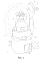
- Fig. 1 is an external perspective view illustrating a storage state of the electric vacuum cleaner according to the embodiment of the present invention.
- the electric vacuum cleaner 1 includes: a vacuum cleaner body 2, a dust collection hose 3, a hand operation pipe 4, a gripping part 5, an operation unit 6, an extension tube 7, a floor suction fitting 8, and a storage base 10.
- the vacuum cleaner body 2 includes a connection port 2a. One end of the dust collection hose 3 is connected to the connection port 2a in an attachable and detachable manner.
- the vacuum cleaner body 2 is configured to be mountable on the storage base 10.
- the dust collection hose 3 is formed into a flexible, curvable, elongate, and substantially cylindrical shape. One end of the dust collection hose 3 is connected to the connection port 2a in an attachable and detachable manner.
- the dust collection hose 3 is communicatively connected to the inside of the vacuum cleaner body 2.
- the dust collection hose 3 has a hand grip 11 (upright gripper unit) located near the connection port 2a of the vacuum cleaner body 2.
- the hand operation pipe 4 is communicatively connected to the inside of the vacuum cleaner body 2 through the dust collection hose 3.
- the gripping part 5 is gripped by a user of the electric vacuum cleaner 1 to operate the electric vacuum cleaner 1.
- the gripping part 5 is projectingly provided in the other end portion of the hand operation pipe 4 and is formed to be curved toward one end portion of the hand operation pipe 4 where the dust collection hose 3 is provided.
- the operation unit 6 is provided on the gripping part 5.
- the user of the electric vacuum cleaner 1 can set the electric vacuum cleaner 1 to a plurality of drive modes by operating the operation unit 6.
- the operation unit 6 includes an off switch 6a for stopping the operation of the electric vacuum cleaner 1 and an on switch 6b for starting the operation of the electric vacuum cleaner 1.
- the extension tube 7 is formed into a stretchable, elongate, and substantially cylindrical shape.
- the extension tube 7 has a telescopic structure made by laminating a plurality of cylindrical bodies.
- On end of the extension tube 7 is connected to the other end of the hand operation pipe 4 in an attachable and detachable manner.
- the extension tube 7 is communicatively connected to the inside of the vacuum cleaner body 2 through the hand operation pipe 4 and the dust collection hose 3.
- the floor suction fitting 8 is connected to one end of the extension tube 7 in an attachable and detachable manner.
- the floor suction fitting 8 is communicatively connected to the inside of the vacuum cleaner body 2 through the extension tube 7, the hand operation pipe 4, and the dust collection hose 3.
- the floor suction fitting 8 has a suction port (unillustrated). When the floor suction fitting 8 is placed on a floor F , the suction port faces the floor F.
- the storage base 10 has a mounting unit 13 and a support post 14.
- the mounting unit 13 has an incline formed upper surface 13a (inclined mounting surface).
- the upper surface 13a of the mounting unit 13 is configured to allow the vacuum cleaner body 2 to be mounted thereon.
- the mounting unit 13 has a swingable pedal 15.
- the support post 14 is provided in an end portion on a lower side of the inclined mounting unit 13.
- the support post 14 extends to be oriented in a substantially vertical upward direction when the storage base 10 is placed on a substantially horizontal floor F.
- An upper end of the support post 14 is engaged with the hand grip 11 of the dust collection hose 3 in an attachable and detachable manner.
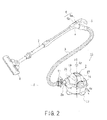
- Fig. 2 is an external perspective view illustrating a use state of the electric vacuum cleaner according to the embodiment of the present invention.
- the electric vacuum cleaner 1 becomes a vacuum cleaner assembly 16 including the vacuum cleaner body 2, the dust collection hose 3, the hand operation pipe 4, the gripping part 5, the operation unit 6, the extension tube 7, and the floor suction fitting 8.
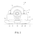
- Fig. 3 is a front view of the vacuum cleaner body of the electric vacuum cleaner according to the embodiment of the present invention.
- Fig. 4 is a plan view of the vacuum cleaner body of the electric vacuum cleaner according to the embodiment of the present invention.
- Fig. 5 is a side view of the vacuum cleaner body of the electric vacuum cleaner according to the embodiment of the present invention.
- the vacuum cleaner body 2 of the electric vacuum cleaner 1 includes the base unit 17 placed on the floor F, an elevation pivot support unit 18 provided on the base unit 17, and a main body 19 pivotably supported about a pivot axis x (in the direction indicated by a solid arrow Rx in Figs. 2 and 5 ) of the elevation pivot support unit 18.
- the base unit 17 When the vacuum cleaner body 2 is stored in the storage base 10, the base unit 17 is placed on the mounting unit 13 of the storage base 10. Meanwhile, when the vacuum cleaner body 2 is detached from the storage base 10 to be used for cleaning, the base unit 17 is placed on the floor F.
- the base unit 17 includes a base unit main body 21 placed on the floor F; a swivel base 22 rotatably supported by the base unit main body 21; and a secondary battery 23 supplying power to the main body 19.
- At least three casters 24 are attached to the bottom surface of the base unit main body 21.
- the casters 24 are arranged such that in a case where an orthographic projection position of the center of gravity of the vacuum cleaner body 2 to the floor F is positioned inside a polygon with each caster 24 at an apex thereof, such as a triangle for three casters 24 and a pentagon for five casters 24.
- the casters 24 are arranged at substantially equal spacings near the outer circumference of the bottom surface of the base unit main body 21.
- the swivel base 22 is rotatably supported about a rotational axis z (in the direction indicated by a solid arrow Rz in Figs. 2 and 4 ) of the base unit main body 21.
- the rotational axis z is positioned in a tangential direction of the floor F.
- the rotational axis z is substantially vertical.
- the swivel base 22 has the elevation pivot support unit 18.
- the secondary battery 23 is housed in the base unit 17. Specifically, the secondary battery 23 is positioned around the main body 19. Note that the secondary battery 23 may be positioned so as to surround the entire circumference of the main body 19, or may be positioned so as to surround only the side circumference of the main body 19 near the elevation pivot support unit 18. Note also that the secondary battery 23 may be housed in any one of the base unit main body 21 and the swivel base 22.
- the elevation pivot support unit 18 pivotably supports the main body 19 about the pivot axis x.
- the pivot axis x is substantially parallel to the floor F.
- the main body 19 is pivotably supported by the elevation pivot support unit 18 from a substantially parallel state in one direction to a substantially parallel state in the other direction with respect to the floor F on which the base unit 17 is placed; and is rotatably supported so as to be rotated 360° about the normal line of the floor by the swivel base 22.
- the main body 19 includes the dust separation/collection unit 26 and the electric blower 27.
- the main body 19 has a main body hand grip 28 and a main body exhaust port (unillustrated) through which air is exhausted from the electric blower 27. Further, the main body 19 has a connection port 2a to which the dust collection hose 3 is connected.
- the substantially parallel state in one direction of the main body 19 refers to a state in which the connection port 2a is oriented in one substantially horizontal direction and the substantially parallel state in the other direction of the main body 19 refers to a state in which the connection port 2a is oriented in the other substantially horizontal direction.
- the main body 19 When the dust collection hose 3 is dragged to pull the vacuum cleaner body 2, the main body 19 appropriately moves up and down and turns with respect to the floor F on which the base unit 17 is placed, thereby suppressing the curving the dust collection hose 3. Specifically, as illustrated in Fig. 5 , the main body 19 appropriately moves up and down following the dragging of the dust collection hose 3. For example, when the dust collection hose 3 is dragged in one direction substantially horizontal to the floor F, the main body 19 makes the connection port 2a follow in one substantially horizontal direction (solid arrow A in Fig. 5 ). Further, when the dust collection hose 3 is dragged in a direction substantially vertical to the floor F, the main body 19 makes the connection port 2a follow in a substantially upward direction (solid arrow B in Fig.
- the main body 19 makes the connection port 2a follow in the other substantially horizontal direction (solid arrow C in Fig. 5 ). Still further, the main body 19 appropriately changes the direction of the connection port 2a following the dragging of the dust collection hose 3 in a pivotable range.
- the electric vacuum cleaner 1 can suppress the dust collection hose 3 from being curved following the dragging of the vacuum cleaner body 2 and can suppress reduction in suction performance due to the curving of the dust collection hose 3.
- the vacuum cleaner body 2 has a click mechanism 30 (attachment/detachment mechanism).
- the click mechanism 30 includes a locking claw 30a formed on the elevation pivot support unit 18; and a locking recess 30b formed on the main body 19.
- the click mechanism 30 is configured such that the main body 19 can be temporarily fixed at a predetermined depression angle or elevation angle by the locking claw 30a and the locking recess 30b which are mutually attachable and detachable.
- the click mechanism 30 temporarily fixes the pivotable main body 19 at an appropriate pivot position.
- the click mechanism 30 can be configured such that the connection port 2a temporarily fixes the main body 19 in a vertically upward state.
- the vacuum cleaner assembly 16 When the vacuum cleaner assembly 16 is used for cleaning, first, the vacuum cleaner body 2 is detached from the storage base 10 of the electric vacuum cleaner 1 and is placed on the floor F. When the on switch 6b of the operation unit 6 is pressed, the vacuum cleaner assembly 16 operates such that the electric blower 12 starts operating and a negative pressure acts on the dust separation/collection unit 26. The negative pressure acts on the floor suction fitting 8 from the connection port 2a, passing through the dust collection hose 3, the hand operation pipe 4, and the extension tube 7. Then, the vacuum cleaner assembly 16 sucks air together with dust accumulated on the floor F from the suction port of the floor suction fitting 8 to clean the floor F.
- the dust-containing air drawn in the floor suction fitting 8 is separated into air and dust by the dust separation/ collection unit 26 housed in the vacuum cleaner body 2.
- the separated dust is collected in the dust separation/collection unit 26.
- the separated air passes through the electric blower 27 and is discharged from the main body exhaust port.
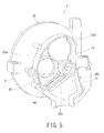
- Fig. 6 is a sectional view illustrating the vacuum cleaner body of the electric vacuum cleaner according to the embodiment of the present invention.
- the vacuum cleaner body 2 of the electric vacuum cleaner 1 includes the base unit 17, the elevation pivot support unit 18, and the main body 19.
- the base unit 17 includes the base unit main body 21 and the swivel base 22.
- the caster 24 of the base unit main body 21 is rotatably supported by a caster shaft 32 provided on the bottom surface of the base unit main body 21.
- the rotational axis Rc of each caster shaft 32 is configured to be substantially vertical to the floor F on which the base unit 17 is placed and on which the caster 24 contacts.
- Each caster shaft 32 is configured to be parallel to each other.
- the rotational axis Rc of the caster shaft 32 does not cross the axle 24a of the caster 24 and is located in a mutually twisted position.
- the main body 19 includes a connection pipe 33 having the connection port 2a of the vacuum cleaner body 2, the dust separation/collection unit 26 (first dust collection unit) communicatively connected to the connection pipe 33, and the electric blower 27 communicatively connected to the dust separation/collection unit 26.
- connection pipe 33 The opening end of the connection pipe 33 is the connection port 2a of the vacuum cleaner body 2.
- the central axis c of the connection pipe 33 is arranged in any one of the directions along a surface (for example, the cross section of Fig. 6 ) orthogonal to the pivot axis x. More specifically, the connection pipe 33 is arranged in a position where the central axis c thereof is along the surface orthogonal to the pivot axis x, the connection port 2a is opened in a direction farther away from the pivot axis x, and the connection pipe 33 is farthest from the pivot axis x.
- the main body 19 includes a dust disposal coupling tube unit 35 (first coupling unit) and an intake coupling tube unit 36 (second coupling unit) located on one side surface such as the bottom surface 19a where the depression angle or the elevation angle change with the up and down movement.
- the dust disposal coupling tube unit 35 communicatively connects the inside of the dust separation/collection unit 26 to the outside of the main body 19.
- the dust disposal coupling tube unit 35 has a gate valve 37 provided in an openable and closable manner.
- the gate valve 37 is urged in a direction of closing the dust disposal coupling tube unit 35.
- the intake coupling tube unit 36 communicatively connects the upstream side of the electric blower 27 to the outside of the main body 19. Further, the intake coupling tube unit 36 has an air path switching unit 38 interposed between the dust separation/collection unit 26 and the electric blower 27.
- the air path switching unit 38 has a switching valve 39.
- the switching valve 39 communicatively connects the inside of the dust separation/collection unit 26 to the upstream side of the electric blower 27 and is urged in a direction of blocking the communication between the upstream side of the electric blower 27 and the outside of the main body 19.
- the main body 19 has main body hand grips 28a and 28b axisymmetrically arranged about pivot axis x.
- the main body hand grip 28a is grippably provided in a pivot position of the main body 19 in a substantially parallel state in one direction to the floor F on which the base unit 17 is placed.
- the main body hand grip 28b is grippably provided in a pivot position of the main body 19 in a substantially parallel state in the other direction to the floor F on which the base unit 17 is placed.
- the vacuum cleaner body 2 can be carried in any state of the main body 19 oriented in any pivot direction by the main body hand grips 28a and 28b.
- the main body hand grips 28a and 28b improve the portability of the vacuum cleaner body 2.
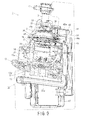
- Fig. 7 and 8 are a perspective view partially illustrating an air path switching unit of the vacuum cleaner body of the electric vacuum cleaner according to the embodiment of the present invention.
- Fig. 7 illustrates the dust separation/collection unit side of the air path switching unit.
- Fig. 8 illustrates the electric blower side of the air path switching unit.
- the air path switching unit 38 of the vacuum cleaner body 2 includes: a plate 41 having a first opening 40 communicatively connecting the dust separation/collection unit 26 to the electric blower 27; a slide plate 42 slidably provided on the plate 41; a link 43 swung by sliding of the slide plate 42; and a switching valve 39 rotated by swinging of the link 43.
- the plate 41 has a partition wall 45 having a second opening 44 communicatively connecting the upstream side of the electric blower 27 to the outside of the main body 19.
- the switching valve 39 includes a first valve body 39a for opening and closing a first opening 40 (communication opening); and a second valve body 39b for opening and closing a second opening 44.
- the first valve body 39a and the second valve body 39b operate in such a manner that when one valve body closes one opening, the other valve body opens the other opening.
- the first valve body 39a and the second valve body 39b operate in such a manner that when the first valve body 39a closes the first opening 40, the second valve body 39b opens the second opening 44.
- the first valve body 39a and the second valve body 39b operate in such a manner that when the second valve body 39b closes the second opening 44, the first valve body 39a opens the first opening 40.
- the switching valve 39 opens the first opening 40 and is urged in the direction of closing the second opening 44 by an elastic member (unillustrated) such as a spring.
- the air path switching unit 38 uses the urging force due to the elastic member to communicatively connect the dust separation/collection unit 26 to the electric blower 27 and block the communication between the upstream side of the electric blower 27 and the outside of the main body 19.
- the air path switching unit 38 activates the switching valve 39 through the link 43 to close the first opening 40 and open the second opening 44. With this operation, the air path switching unit 38 blocks the communication between the dust separation/collection unit 26 and the electric blower 27 and communicatively connects the upstream side of the electric blower 27 to the outside of the main body 19 (two-dot chain line in Figs. 7 and 8 ).
- Fig. 9 is a partially cut-out perspective view illustrating the electric vacuum cleaner according to the embodiment of the present invention.
- the storage base 10 of the electric vacuum cleaner 1 includes: a dust accumulation unit 47 (second dust collection unit) having a volume larger than that of the dust separation/collection unit 26 of the vacuum cleaner body 2; a dust suction tube 48 one end portion of which is provided in the support post 14 and the other end portion of which is communicatively connected to the dust accumulation unit 47; an exhaust pipe 49 one end portion of which is provided in the support post 14 and the other end portion of which is communicatively connected to the dust accumulation unit 47; and a slide mechanism 51 provided above the mounting unit 13.
- the storage base 10 has a charging mechanism (unillustrated) for charging the secondary battery 23 of the vacuum cleaner body 2.
- the dust accumulation unit 47 is housed in the mounting unit 13.
- Opening ends 48a and 49a abutting against one end portion of the dust suction tube 48 and the exhaust pipe 49 is arranged in the support post 14.
- the opening end 48a of the dust suction tube 48 is formed in the dust disposal coupling tube unit 35 of the vacuum cleaner body 2 in an attachable and detachable manner.
- the opening end 49a of the exhaust pipe 49 is formed in the intake coupling tube unit 36 of the vacuum cleaner body 2 in an attachable and detachable manner.
- the relative positional relation between the opening end 48a of the dust suction tube 48 and the opening end 49a of the exhaust pipe 49 is an arrangement corresponding to the relative positional relation between the dust disposal coupling tube unit 35 and the intake coupling tube unit 36.
- the slide mechanism 51 has a protruded portion 51a formed to be projected from the upper surface 13a of the mounting unit 13.
- the protruded portion 51 a is formed in an attachable and detachable manner in the recessed portion 17a located on the bottom surface of the base unit 17 of the vacuum cleaner body 2.
- the slide mechanism 51 is configured to be able to reciprocate the protruded portion 51 a up and down along the inclination of the upper surface 13a of the mounting unit 13.
- the charging mechanism When the vacuum cleaner body 2 is placed on the upper surface 13a of the mounting unit 13, the charging mechanism electrically connects the storage base 10 and the vacuum cleaner body 2. Thus, the secondary battery 23 is charged.
- the charging mechanism may electrically connect contact points (unillustrated) each provided in the vacuum cleaner body 2 and the storage base 10 or may electrically connect them in a contactless manner.
- the slide mechanism 51 slides down on the upper surface 13a of the mounting unit 13 by weight of the vacuum cleaner body 2 and guides the vacuum cleaner body 2 to the support post 14.
- the electric vacuum cleaner 1 moves the vacuum cleaner body 2 closer to the support post 14 and moves the main body 19 of the vacuum cleaner body 2 up, down, or turns into an appropriate storage posture.
- the opening end 48a of the dust suction tube 48 is joined to the dust disposal coupling tube unit 35 of the vacuum cleaner body 2, while the opening end 49a of the exhaust pipe 49 is joined to the intake coupling tube unit 36 of the vacuum cleaner body 2.
- the slide plate 42 is pushed inward of the main body 19 by a plate-like protrusion 14a provided in the support post 14, the air path switching unit 38 of the vacuum cleaner body 2 activates the switching valve 39.
- the storage posture of the vacuum cleaner body 2 may be a posture in which the main body 19 can be freely moved up and down, and the user of the electric vacuum cleaner 1 is gripping the hand grip 11 of the dust collection hose 3 with the main body 19 maintained at a predetermined depression angle or elevation angle or a posture in which the main body 19 is temporarily fixed at a predetermined depression angle or elevation angle by the click mechanism 30 of the vacuum cleaner body 2.
- the electric vacuum cleaner 1 stores the vacuum cleaner body 2 in the storage base 10 and communicatively connects the dust separation/collection unit 26 of the vacuum cleaner body 2, the dust accumulation unit 47 of the storage base 10, and the electric blower 27 of the vacuum cleaner body 2 in series.
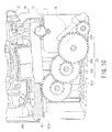
- Fig. 10 is a partially cut-out perspective view illustrating the storage unit of the electric vacuum cleaner according to the embodiment of the present invention.
- the storage base 10 includes a pedal 15 swingably provided in the mounting unit 13; and a slide drive mechanism 53 which transmits the drive power of the pedal 15 to the slide mechanism 51.
- the pedal 15 is pressed down, such as by stepping the slide mechanism 51 is moved upward on the inclination of the upper surface 13a of the mounting unit 13 by the slide drive mechanism 53.
- the vacuum cleaner body 2 is moved upward on the inclination of the upper surface 13a of the mounting unit 13.
- the slide mechanism 51 has a rack 51b.
- the slide drive mechanism 53 has a plurality of gears 53a, 53b, 53c, and 53d.
- the slide drive mechanism 53 sequentially transmits the drive power applied to the pedal 15 to the gears 53a, 53b, 53c, and 53d and causes the slide mechanism 51 to be driven by the rack 51b engaged with the gear 53d.
- the user of the electric vacuum cleaner 1 detaches the vacuum cleaner body 2 from the storage base 10. At this time, the user of the electric vacuum cleaner 1 grips the hand grip 11 of the dust collection hose 3 and releases the lock between the hand grip 11 and the support post 14. At the same time, the user steps down the pedal 15 of the storage base 10 to detach the vacuum cleaner body 2 on the mounting unit 13 from the support post 14. Then, the user of the electric vacuum cleaner 1 can easily detach the vacuum cleaner body 2 from the upper surface 13a of the mounting unit 13.
- the user of the electric vacuum cleaner 1 places the vacuum cleaner body 2 detached from the storage base 10 on the floor F such as a floor surface.
- the user of the electric vacuum cleaner 1 places the floor suction fitting 8 on the floor F and operates the on switch 6b with the gripping part 5 being gripped. Then, the electric blower 27 operates according to the operation mode set by the on switch 6b.
- the user of the electric vacuum cleaner 1 moves the hand operation pipe 4 and the extension tube 7 with the gripping part 5 being gripped to run the floor suction fitting 8.
- the hand operation pipe 4 the extension tube 7, and the floor suction fitting 8 reciprocate back and forth.
- the main body 19 of the vacuum cleaner body 2 moves up and down about the pivot axis x of the elevation pivot support unit 18 following the curving of the dust collection hose 3. This also applied to a case in which the user of the electric vacuum cleaner 1 repeatedly moves the gripping part 5 up and down to clean a wall.
- the vacuum cleaner body 2 rotates about the rotational axis z following the curving of the dust collection hose 3 by means of the swivel base 22 or the casters 24.
- the vacuum cleaner body 2 moves up or down and turns following the curving of the dust collection hose 3 by means of the elevation pivot support unit 18, the swivel base 22, and the casters 24 to run on the floor F.
- the dust on the floor F is drawn together with air in the suction port of the floor suction fitting 8.
- the dust-containing air sucked into the floor suction fitting 8 passes through the extension tube 7, the hand operation pipe 4, and the dust collection hose 3 in that order and passes through the connection port 2a of the vacuum cleaner body 2 and is drawn inside the vacuum cleaner body 2.
- the dust-containing air drawn inside the vacuum cleaner body 2 is guided to the dust separation/collection unit 26.
- the dust-containing air is separated into air and dust by the dust separation/collection unit 26.
- the separated dust is collected by the dust separation/collection unit 26.
- the separated air is drawn in by the electric blower 27, passes through the electric blower 27 by cooling the electric blower 27, and then is discharged from the main body exhaust port to outside the vacuum cleaner body 2.
- the user of the electric vacuum cleaner 1 carries the vacuum cleaner assembly 16 near the storage base 10, and lifts the vacuum cleaner body 2 by gripping the hand grip 11 provided on the dust collection hose 3.
- the main body 19 is oriented upward and the vacuum cleaner body 2 orients the connection port 2a upward with the dust collection hose 3 connected thereto.
- the user of the electric vacuum cleaner 1 carries the vacuum cleaner body 2 above the mounting unit 13, and fits the recessed portion 17a of the vacuum cleaner body 2 into the protruded portion 51a of the storage base 10.
- the vacuum cleaner body 2 slides the slide mechanism 51 and goes down on the upper surface 13a of the mounting unit 13 until the vacuum cleaner body 2 comes closer to the support post 14.
- the user of the electric vacuum cleaner 1 grips the hand grip 11 to move up or down or turn the main body 19 to put the vacuum cleaner body 2 in an appropriate storage posture.
- the opening end 48a of the dust suction tube 48 is joined to the dust disposal coupling tube unit 35 of the vacuum cleaner body 2.
- the opening end 49a of the exhaust pipe 49 is joined to the intake coupling tube unit 36 of the vacuum cleaner body 2.
- the slide plate 42 of the vacuum cleaner body 2 is pressed into the plate-like protrusion 14a provided in the support post 14 to activate the switching valve 39.
- the electric vacuum cleaner 1 stores the vacuum cleaner body 2 in the storage base 10 and communicatively connects the dust separation/collection unit 26 of the vacuum cleaner body 2, the dust accumulation unit 47 of the storage base 10, and the electric blower 27 of the electric vacuum cleaner body in series.
- the electric vacuum cleaner 1 operates the electric blower 27 for a required time. Accordingly, the dust accumulated in the dust separation/collection unit 26 together with air passes through the dust suction tube 48 and is guided to the dust accumulation unit 47. The dust-containing air guided to the dust accumulation unit 47 is separated into air and dust in the dust accumulation unit 47. The separated dust is collected in the dust accumulation unit 47. Meanwhile, the separated air passes through the exhaust pipe 49 and is drawn in the electric blower 27, passes through the electric blower 27, and is discharged from the main body exhaust port to outside the vacuum cleaner body 2.
- the electric vacuum cleaner 1 when the vacuum cleaner body 2 is placed on the storage base 10, first, the weight of the vacuum cleaner body 2 is put on the storage base 10, and subsequently, the dust separation/collection unit 26 and the dust accumulation unit 47 of the main body 19 can be communicatively connected to each other by a sufficiently small force compared to that required to carry the vacuum cleaner body 2. Accordingly, the electric vacuum cleaner 1 can separately perform the operation of placing the vacuum cleaner body 2 on the storage base 10 and the operation of communicatively connecting the dust separation/collection unit 26 and the dust accumulation unit 47, and thus the dust disposal coupling tube unit 35 and the intake coupling tube unit 36 of the vacuum cleaner body 2, the dust suction tube 48 and the exhaust pipe 49 of the storage base 10 can be securely connected.
- the elevation pivot support unit 18, the swivel base 22, and the casters 24 can improve the lightness of handleability of the vacuum cleaner body 2, and can reliably communicatively connect the dust separation/collection unit 26 and the dust accumulation unit 47 while the main body 19 having the dust disposal coupling tube unit 35 and the intake coupling tube unit 36 is moving up or down or turning.
- the dust accumulated in the vacuum cleaner body 2 is collected again in the storage base 10 each time the vacuum cleaner body 2 is stored in the storage base 10. Accordingly, the dust collectability of the vacuum cleaner assembly 16 can be maintained for a long period of time.
- the electric vacuum cleaner 1 of the embodiment of the present invention enables lightness of handleability of the vacuum cleaner body 2, can stably attach and detach the storage base 10 to and from the vacuum cleaner body 2, and can maintain a long-term dust collectability of the vacuum cleaner body 2.
Landscapes
- Engineering & Computer Science (AREA)
- Mechanical Engineering (AREA)
- Electric Suction Cleaners (AREA)
- Electric Vacuum Cleaner (AREA)
Abstract
Description
- The present invention relates to an electric vacuum cleaner having a storage base and a vacuum cleaner body mountable on the storage base.
- A conventional electric vacuum cleaner includes a vacuum cleaner body having a first dust separation/collection unit; and a charging base having a second dust separation/collection unit. The conventional electric vacuum cleaner uses the vacuum cleaner body detached from the charging base to collect dust on a floor. Subsequently, when the vacuum cleaner body is mounted on the charging base, the first dust separation/ collection unit is communicatively connected to the second dust separation/collection unit, and the conventional electric vacuum cleaner recollects the dust collected in the first dust separation/collection unit of the vacuum cleaner body into the second dust separation/collection unit of the charging base. (For example, see Patent Document 1).
Patent Document 1: Japanese Patent Laid-Open No.2008-79922 - When the vacuum cleaner body is mounted on the charging base, the conventional electric vacuum cleaner needs to appropriately couple the charging base and the vacuum cleaner body by lifting the vacuum cleaner body and adjusting the relative positional relation between the charging base and the vacuum cleaner body. In addition, the conventional electric vacuum cleaner matches the bottom surface of the vacuum cleaner body and the upper surface of the charging base to form a mutual coupling surface and at the same time communicatively connect the first dust separation/ collection unit to the second dust separation/collection unit in the coupling surface.
- As described above, the conventional electric vacuum cleaner has a configuration of almost simultaneously attaching and detaching the coupling mechanism between the charging base and the vacuum cleaner body; and the communication mechanism between the first dust separation/ collection unit and the second dust separation/ collection unit. Thus, unfortunately, load caused by inertial force of the vacuum cleaner body prevents reliable connections of the coupling mechanism and the communication mechanism and may prevent a reliable formation of a communication path between the first dust separation/collection unit and the second dust separation/collection unit. Further, the conventional electric vacuum cleaner has a configuration of almost simultaneously attaching and detaching the coupling mechanism between the charging base and the vacuum cleaner body; and the communication mechanism between the first dust separation/collection unit and the second dust separation/collection unit. Thus, unfortunately, improving the handleability of the vacuum cleaner body reduces the freedom of selecting a structural type of the vacuum cleaner body.
- The present invention proposes an electric vacuum cleaner which has a light handleability of the vacuum cleaner body, can stably attach and detach the storage unit to and from the vacuum cleaner body, and can maintain a long-term dust collectability of the vacuum cleaner body.
- In order to solve the above problems, an electric vacuum cleaner according to the present invention comprises: a storage base and a vacuum cleaner body mountable on the storage base, the vacuum cleaner body comprising: a base unit mountable on the storage base; an elevation pivot support unit provided on the base unit a main body pivotably supported by the elevation pivot support unit; a first dust collection unit provided on the main body; an electric blower housed in the main body and communicatively connected to the first dust collection unit; a first coupling unit communicatively connected to the first dust collection unit and closed in an openable and closable manner; a second coupling unit communicatively connected to the electric blower and closed in an openable and closable manner; and a switching valve which is interposed between the first dust collection unit and the electric blower, and closes a communication opening between the first dust collection unit and the electric blower when the second coupling unit opens, the storage base comprising: a mounting unit of the vacuum cleaner body; a second dust collection unit provided in the mounting unit; a dust suction tube formed in the first coupling unit in an attachable and detachable manner and communicatively connected to the second dust collection unit; and an exhaust pipe communicatively connected to the second dust collection unit and formed in the second coupling unit in an attachable and detachable manner, wherein when the vacuum cleaner body is mounted on the mounting unit and the main body is appropriately moved up and down, the first coupling unit is joined to the dust suction tube and the second coupling unit is joined to the exhaust pipe.
Thus, the present invention can propose an electric vacuum cleaner which is excellent in handleability of the vacuum cleaner body, can stably attach and detach the storage unit to and from the vacuum cleaner body, and can maintain a long-term dust collectability of the vacuum cleaner body. -
-
Fig. 1 is an external perspective view illustrating a storage state of an electric vacuum cleaner according to an embodiment of the present invention. -
Fig. 2 is an external perspective view illustrating a use state of the electric vacuum cleaner according to the embodiment of the present invention. -
Fig. 3 is a front view of a vacuum cleaner body of the electric vacuum cleaner according to the embodiment of the present invention. -
Fig. 4 is a plan view of the vacuum cleaner body of the electric vacuum cleaner according to the embodiment of the present invention. -
Fig. 5 is a side view of the vacuum cleaner body of the electric vacuum cleaner according to the embodiment of the present invention. -
Fig. 6 is a sectional view illustrating the vacuum cleaner body of the electric vacuum cleaner according to the embodiment of the present invention. -
Fig. 7 is a perspective view partially illustrating an air path switching unit of the vacuum cleaner body of the electric vacuum cleaner according to the embodiment of the present invention. -
Fig. 8 is a perspective view partially illustrating an air path switching unit of the vacuum cleaner body of the electric vacuum cleaner according to the embodiment of the present invention. -
Fig. 9 is a partially cut-out perspective view illustrating the electric vacuum cleaner according to the embodiment of the present invention. -
Fig. 10 is a partially cut-out perspective view illustrating the storage unit of the electric vacuum cleaner according to the embodiment of the present invention. -
- 1
- electric vacuum cleaner
- 2
- vacuum cleaner body
- 2a
- connection port
- 3
- dust collection hose
- 4
- hand operation pipe
- 5
- gripper unit
- 6
- operation unit
- 6a
- off switch
- 6b
- on switch
- 7
- extension tube
- 8
- floor suction fitting
- 10
- storage base
- 11
- hand grip
- 13
- mounting unit
- 13a
- upper surface
- 14
- support post
- 14a
- protrusion
- 15
- pedal
- 16
- vacuum cleaner assembly
- 17
- base unit
- 17a
- recessed portion
- 18
- elevation pivot support unit
- 19
- main body
- 19a
- bottom surface
- 21
- base unit main body
- 22
- swivel base
- 23
- secondary battery
- 24
- caster
- 24a
- axle
- 26
- dust separation/collection unit
- 27
- electric blower
- 28
- main body hand grip
- 30
- click mechanism
- 30a
- locking claw
- 30b
- locking recess
- 32
- caster shaft
- 33
- connection pipe
- 35
- dust disposal coupling tube unit
- 36
- intake coupling tube unit
- 37
- gate valve
- 38
- air path switching unit
- 39
- switching valve
- 39a
- first valve body
- 39b
- second valve body
- 40
- first opening
- 41
- plate
- 42
- slide plate
- 43
- link
- 44
- second opening
- 45
- partition wall
- 47
- dust accumulation unit
- 48
- dust suction tube
- 48a
- opening end
- 49
- exhaust pipe
- 49a
- opening end
- 51
- slide mechanism
- 51a
- protrusion
- 51b
- rack
- 53
- slide drive mechanism
- 53a
- gear
- An embodiment of an electric vacuum cleaner according to the present invention will be described by referring to the
Figs. 1 to 10 . -
Fig. 1 is an external perspective view illustrating a storage state of the electric vacuum cleaner according to the embodiment of the present invention. - As illustrated in
Fig. 1 , theelectric vacuum cleaner 1 according to the present embodiment includes: avacuum cleaner body 2, adust collection hose 3, a hand operation pipe 4, agripping part 5, anoperation unit 6, anextension tube 7, a floor suction fitting 8, and astorage base 10. - The
vacuum cleaner body 2 includes aconnection port 2a. One end of thedust collection hose 3 is connected to theconnection port 2a in an attachable and detachable manner. Thevacuum cleaner body 2 is configured to be mountable on thestorage base 10. - The
dust collection hose 3 is formed into a flexible, curvable, elongate, and substantially cylindrical shape. One end of thedust collection hose 3 is connected to theconnection port 2a in an attachable and detachable manner. Thedust collection hose 3 is communicatively connected to the inside of thevacuum cleaner body 2. Thedust collection hose 3 has a hand grip 11 (upright gripper unit) located near theconnection port 2a of thevacuum cleaner body 2. - One end of the hand operation pipe 4 is provided in the other end of the
dust collection hose 3. The hand operation pipe 4 is communicatively connected to the inside of thevacuum cleaner body 2 through thedust collection hose 3. - The
gripping part 5 is gripped by a user of theelectric vacuum cleaner 1 to operate theelectric vacuum cleaner 1. Thegripping part 5 is projectingly provided in the other end portion of the hand operation pipe 4 and is formed to be curved toward one end portion of the hand operation pipe 4 where thedust collection hose 3 is provided. - The
operation unit 6 is provided on thegripping part 5. The user of theelectric vacuum cleaner 1 can set theelectric vacuum cleaner 1 to a plurality of drive modes by operating theoperation unit 6. Theoperation unit 6 includes anoff switch 6a for stopping the operation of theelectric vacuum cleaner 1 and an onswitch 6b for starting the operation of theelectric vacuum cleaner 1. - The
extension tube 7 is formed into a stretchable, elongate, and substantially cylindrical shape. Theextension tube 7 has a telescopic structure made by laminating a plurality of cylindrical bodies. On end of theextension tube 7 is connected to the other end of the hand operation pipe 4 in an attachable and detachable manner. Theextension tube 7 is communicatively connected to the inside of thevacuum cleaner body 2 through the hand operation pipe 4 and thedust collection hose 3. - The floor suction fitting 8 is connected to one end of the
extension tube 7 in an attachable and detachable manner. The floor suction fitting 8 is communicatively connected to the inside of thevacuum cleaner body 2 through theextension tube 7, the hand operation pipe 4, and thedust collection hose 3. The floor suction fitting 8 has a suction port (unillustrated). When the floor suction fitting 8 is placed on a floor F , the suction port faces the floor F. - The
storage base 10 has a mountingunit 13 and asupport post 14. The mountingunit 13 has an incline formedupper surface 13a (inclined mounting surface). Theupper surface 13a of the mountingunit 13 is configured to allow thevacuum cleaner body 2 to be mounted thereon. The mountingunit 13 has aswingable pedal 15. Thesupport post 14 is provided in an end portion on a lower side of the inclined mountingunit 13. Thesupport post 14 extends to be oriented in a substantially vertical upward direction when thestorage base 10 is placed on a substantially horizontal floor F. An upper end of thesupport post 14 is engaged with thehand grip 11 of thedust collection hose 3 in an attachable and detachable manner. -
Fig. 2 is an external perspective view illustrating a use state of the electric vacuum cleaner according to the embodiment of the present invention. - As illustrated in
Fig. 2 , in the state in which thevacuum cleaner body 2 is detached from thestorage base 10 and is placed on the floor F, theelectric vacuum cleaner 1 becomes a vacuumcleaner assembly 16 including thevacuum cleaner body 2, thedust collection hose 3, the hand operation pipe 4, thegripping part 5, theoperation unit 6, theextension tube 7, and the floor suction fitting 8. -
Fig. 3 is a front view of the vacuum cleaner body of the electric vacuum cleaner according to the embodiment of the present invention. -
Fig. 4 is a plan view of the vacuum cleaner body of the electric vacuum cleaner according to the embodiment of the present invention. -
Fig. 5 is a side view of the vacuum cleaner body of the electric vacuum cleaner according to the embodiment of the present invention. - As illustrated in
Figs. 2 to 5 , thevacuum cleaner body 2 of theelectric vacuum cleaner 1 includes thebase unit 17 placed on the floor F, an elevationpivot support unit 18 provided on thebase unit 17, and amain body 19 pivotably supported about a pivot axis x (in the direction indicated by a solid arrow Rx inFigs. 2 and5 ) of the elevationpivot support unit 18. - When the
vacuum cleaner body 2 is stored in thestorage base 10, thebase unit 17 is placed on the mountingunit 13 of thestorage base 10. Meanwhile, when thevacuum cleaner body 2 is detached from thestorage base 10 to be used for cleaning, thebase unit 17 is placed on the floor F. Thebase unit 17 includes a base unitmain body 21 placed on the floor F; aswivel base 22 rotatably supported by the base unitmain body 21; and asecondary battery 23 supplying power to themain body 19. - At least three casters 24 (wheels) are attached to the bottom surface of the base unit
main body 21. When thevacuum cleaner body 2 is placed on the substantially horizontal floor F, thecasters 24 are arranged such that in a case where an orthographic projection position of the center of gravity of thevacuum cleaner body 2 to the floor F is positioned inside a polygon with eachcaster 24 at an apex thereof, such as a triangle for threecasters 24 and a pentagon for fivecasters 24. Specifically, thecasters 24 are arranged at substantially equal spacings near the outer circumference of the bottom surface of the base unitmain body 21. Thus, thevacuum cleaner body 2 can stably run and rotate on the floor F due to thecasters 24. - The
swivel base 22 is rotatably supported about a rotational axis z (in the direction indicated by a solid arrow Rz inFigs. 2 and4 ) of the base unitmain body 21. When thevacuum cleaner body 2 is placed on the floor F, the rotational axis z is positioned in a tangential direction of the floor F. Specifically, when thevacuum cleaner body 2 is placed on the floor F such as a substantially horizontal floor, the rotational axis z is substantially vertical. Theswivel base 22 has the elevationpivot support unit 18. - The
secondary battery 23 is housed in thebase unit 17. Specifically, thesecondary battery 23 is positioned around themain body 19. Note that thesecondary battery 23 may be positioned so as to surround the entire circumference of themain body 19, or may be positioned so as to surround only the side circumference of themain body 19 near the elevationpivot support unit 18. Note also that thesecondary battery 23 may be housed in any one of the base unitmain body 21 and theswivel base 22. - The elevation
pivot support unit 18 pivotably supports themain body 19 about the pivot axis x. When thevacuum cleaner body 2 is placed on the floor F such as a substantially horizontal floor, the pivot axis x is substantially parallel to the floor F. - The
main body 19 is pivotably supported by the elevationpivot support unit 18 from a substantially parallel state in one direction to a substantially parallel state in the other direction with respect to the floor F on which thebase unit 17 is placed; and is rotatably supported so as to be rotated 360° about the normal line of the floor by theswivel base 22. Themain body 19 includes the dust separation/collection unit 26 and theelectric blower 27. Themain body 19 has a mainbody hand grip 28 and a main body exhaust port (unillustrated) through which air is exhausted from theelectric blower 27. Further, themain body 19 has aconnection port 2a to which thedust collection hose 3 is connected. Note that the substantially parallel state in one direction of themain body 19 refers to a state in which theconnection port 2a is oriented in one substantially horizontal direction and the substantially parallel state in the other direction of themain body 19 refers to a state in which theconnection port 2a is oriented in the other substantially horizontal direction. - When the
dust collection hose 3 is dragged to pull thevacuum cleaner body 2, themain body 19 appropriately moves up and down and turns with respect to the floor F on which thebase unit 17 is placed, thereby suppressing the curving thedust collection hose 3. Specifically, as illustrated inFig. 5 , themain body 19 appropriately moves up and down following the dragging of thedust collection hose 3. For example, when thedust collection hose 3 is dragged in one direction substantially horizontal to the floor F, themain body 19 makes theconnection port 2a follow in one substantially horizontal direction (solid arrow A inFig. 5 ). Further, when thedust collection hose 3 is dragged in a direction substantially vertical to the floor F, themain body 19 makes theconnection port 2a follow in a substantially upward direction (solid arrow B inFig. 5 ). Furthermore, when thedust collection hose 3 is dragged in the other direction substantially horizontal to the floor F, themain body 19 makes theconnection port 2a follow in the other substantially horizontal direction (solid arrow C inFig. 5 ). Still further, themain body 19 appropriately changes the direction of theconnection port 2a following the dragging of thedust collection hose 3 in a pivotable range. Thus, theelectric vacuum cleaner 1 can suppress thedust collection hose 3 from being curved following the dragging of thevacuum cleaner body 2 and can suppress reduction in suction performance due to the curving of thedust collection hose 3. - The
vacuum cleaner body 2 has a click mechanism 30 (attachment/detachment mechanism). Theclick mechanism 30 includes a locking claw 30a formed on the elevationpivot support unit 18; and a locking recess 30b formed on themain body 19. Theclick mechanism 30 is configured such that themain body 19 can be temporarily fixed at a predetermined depression angle or elevation angle by the locking claw 30a and the locking recess 30b which are mutually attachable and detachable. When the locking claw 30a and the locking recess 30b are attached to each other, theclick mechanism 30 temporarily fixes the pivotablemain body 19 at an appropriate pivot position. Specifically, when thevacuum cleaner body 2 is placed on the floor F such as a substantially horizontal floor, theclick mechanism 30 can be configured such that theconnection port 2a temporarily fixes themain body 19 in a vertically upward state. - When the vacuum
cleaner assembly 16 is used for cleaning, first, thevacuum cleaner body 2 is detached from thestorage base 10 of theelectric vacuum cleaner 1 and is placed on the floor F. When the onswitch 6b of theoperation unit 6 is pressed, the vacuumcleaner assembly 16 operates such that the electric blower 12 starts operating and a negative pressure acts on the dust separation/collection unit 26. The negative pressure acts on the floor suction fitting 8 from theconnection port 2a, passing through thedust collection hose 3, the hand operation pipe 4, and theextension tube 7. Then, the vacuumcleaner assembly 16 sucks air together with dust accumulated on the floor F from the suction port of the floor suction fitting 8 to clean the floor F. The dust-containing air drawn in the floor suction fitting 8 is separated into air and dust by the dust separation/collection unit 26 housed in thevacuum cleaner body 2. The separated dust is collected in the dust separation/collection unit 26. The separated air passes through theelectric blower 27 and is discharged from the main body exhaust port. -
Fig. 6 is a sectional view illustrating the vacuum cleaner body of the electric vacuum cleaner according to the embodiment of the present invention. - As illustrated in
Fig. 6 , thevacuum cleaner body 2 of theelectric vacuum cleaner 1 includes thebase unit 17, the elevationpivot support unit 18, and themain body 19. - The
base unit 17 includes the base unitmain body 21 and theswivel base 22. - The
caster 24 of the base unitmain body 21 is rotatably supported by acaster shaft 32 provided on the bottom surface of the base unitmain body 21. The rotational axis Rc of eachcaster shaft 32 is configured to be substantially vertical to the floor F on which thebase unit 17 is placed and on which thecaster 24 contacts. Eachcaster shaft 32 is configured to be parallel to each other. The rotational axis Rc of thecaster shaft 32 does not cross the axle 24a of thecaster 24 and is located in a mutually twisted position. - The
main body 19 includes aconnection pipe 33 having theconnection port 2a of thevacuum cleaner body 2, the dust separation/collection unit 26 (first dust collection unit) communicatively connected to theconnection pipe 33, and theelectric blower 27 communicatively connected to the dust separation/collection unit 26. - The opening end of the
connection pipe 33 is theconnection port 2a of thevacuum cleaner body 2. The central axis c of theconnection pipe 33 is arranged in any one of the directions along a surface (for example, the cross section ofFig. 6 ) orthogonal to the pivot axis x. More specifically, theconnection pipe 33 is arranged in a position where the central axis c thereof is along the surface orthogonal to the pivot axis x, theconnection port 2a is opened in a direction farther away from the pivot axis x, and theconnection pipe 33 is farthest from the pivot axis x. - Further, the
main body 19 includes a dust disposal coupling tube unit 35 (first coupling unit) and an intake coupling tube unit 36 (second coupling unit) located on one side surface such as thebottom surface 19a where the depression angle or the elevation angle change with the up and down movement. - The dust disposal
coupling tube unit 35 communicatively connects the inside of the dust separation/collection unit 26 to the outside of themain body 19. The dust disposalcoupling tube unit 35 has agate valve 37 provided in an openable and closable manner. Thegate valve 37 is urged in a direction of closing the dust disposalcoupling tube unit 35. - The intake
coupling tube unit 36 communicatively connects the upstream side of theelectric blower 27 to the outside of themain body 19. Further, the intakecoupling tube unit 36 has an airpath switching unit 38 interposed between the dust separation/collection unit 26 and theelectric blower 27. The airpath switching unit 38 has a switchingvalve 39. The switchingvalve 39 communicatively connects the inside of the dust separation/collection unit 26 to the upstream side of theelectric blower 27 and is urged in a direction of blocking the communication between the upstream side of theelectric blower 27 and the outside of themain body 19. - Further, the
main body 19 has main body hand grips 28a and 28b axisymmetrically arranged about pivot axis x. The main body hand grip 28a is grippably provided in a pivot position of themain body 19 in a substantially parallel state in one direction to the floor F on which thebase unit 17 is placed. On the other hand, the main body hand grip 28b is grippably provided in a pivot position of themain body 19 in a substantially parallel state in the other direction to the floor F on which thebase unit 17 is placed. Thevacuum cleaner body 2 can be carried in any state of themain body 19 oriented in any pivot direction by the main body hand grips 28a and 28b. The main body hand grips 28a and 28b improve the portability of thevacuum cleaner body 2. -
Fig. 7 and8 are a perspective view partially illustrating an air path switching unit of the vacuum cleaner body of the electric vacuum cleaner according to the embodiment of the present invention.Fig. 7 illustrates the dust separation/collection unit side of the air path switching unit.Fig. 8 illustrates the electric blower side of the air path switching unit. - As illustrated in
Figs. 7 and8 , the airpath switching unit 38 of thevacuum cleaner body 2 includes: aplate 41 having afirst opening 40 communicatively connecting the dust separation/collection unit 26 to theelectric blower 27; aslide plate 42 slidably provided on theplate 41; alink 43 swung by sliding of theslide plate 42; and a switchingvalve 39 rotated by swinging of thelink 43. - The
plate 41 has a partition wall 45 having asecond opening 44 communicatively connecting the upstream side of theelectric blower 27 to the outside of themain body 19. - The switching
valve 39 includes afirst valve body 39a for opening and closing a first opening 40 (communication opening); and asecond valve body 39b for opening and closing asecond opening 44. Thefirst valve body 39a and thesecond valve body 39b operate in such a manner that when one valve body closes one opening, the other valve body opens the other opening. Specifically, thefirst valve body 39a and thesecond valve body 39b operate in such a manner that when thefirst valve body 39a closes thefirst opening 40, thesecond valve body 39b opens thesecond opening 44. In contrast to this, thefirst valve body 39a and thesecond valve body 39b operate in such a manner that when thesecond valve body 39b closes thesecond opening 44, thefirst valve body 39a opens thefirst opening 40. The switchingvalve 39 opens thefirst opening 40 and is urged in the direction of closing thesecond opening 44 by an elastic member (unillustrated) such as a spring. The airpath switching unit 38 uses the urging force due to the elastic member to communicatively connect the dust separation/collection unit 26 to theelectric blower 27 and block the communication between the upstream side of theelectric blower 27 and the outside of themain body 19. - When the
slide plate 42 is pushed inward of themain body 19, the airpath switching unit 38 activates the switchingvalve 39 through thelink 43 to close thefirst opening 40 and open thesecond opening 44. With this operation, the airpath switching unit 38 blocks the communication between the dust separation/collection unit 26 and theelectric blower 27 and communicatively connects the upstream side of theelectric blower 27 to the outside of the main body 19 (two-dot chain line inFigs. 7 and8 ). -
Fig. 9 is a partially cut-out perspective view illustrating the electric vacuum cleaner according to the embodiment of the present invention. - As illustrated in
Fig. 9 , thestorage base 10 of theelectric vacuum cleaner 1 includes: a dust accumulation unit 47 (second dust collection unit) having a volume larger than that of the dust separation/collection unit 26 of thevacuum cleaner body 2; adust suction tube 48 one end portion of which is provided in thesupport post 14 and the other end portion of which is communicatively connected to thedust accumulation unit 47; anexhaust pipe 49 one end portion of which is provided in thesupport post 14 and the other end portion of which is communicatively connected to thedust accumulation unit 47; and aslide mechanism 51 provided above the mountingunit 13. In addition, thestorage base 10 has a charging mechanism (unillustrated) for charging thesecondary battery 23 of thevacuum cleaner body 2. - The
dust accumulation unit 47 is housed in the mountingunit 13. - Opening ends 48a and 49a abutting against one end portion of the
dust suction tube 48 and theexhaust pipe 49 is arranged in thesupport post 14. The openingend 48a of thedust suction tube 48 is formed in the dust disposalcoupling tube unit 35 of thevacuum cleaner body 2 in an attachable and detachable manner. In contrast, the openingend 49a of theexhaust pipe 49 is formed in the intakecoupling tube unit 36 of thevacuum cleaner body 2 in an attachable and detachable manner. The relative positional relation between the openingend 48a of thedust suction tube 48 and the openingend 49a of theexhaust pipe 49 is an arrangement corresponding to the relative positional relation between the dust disposalcoupling tube unit 35 and the intakecoupling tube unit 36. - The
slide mechanism 51 has a protrudedportion 51a formed to be projected from theupper surface 13a of the mountingunit 13. The protrudedportion 51 a is formed in an attachable and detachable manner in the recessedportion 17a located on the bottom surface of thebase unit 17 of thevacuum cleaner body 2. Theslide mechanism 51 is configured to be able to reciprocate the protrudedportion 51 a up and down along the inclination of theupper surface 13a of the mountingunit 13. - When the
vacuum cleaner body 2 is placed on theupper surface 13a of the mountingunit 13, the charging mechanism electrically connects thestorage base 10 and thevacuum cleaner body 2. Thus, thesecondary battery 23 is charged. The charging mechanism may electrically connect contact points (unillustrated) each provided in thevacuum cleaner body 2 and thestorage base 10 or may electrically connect them in a contactless manner. - When the
vacuum cleaner body 2 is carried on theupper surface 13a of the mountingunit 13 and the recessedportion 17a of thevacuum cleaner body 2 is inserted into a protrudedportion 51a of theslide mechanism 51, theslide mechanism 51 slides down on theupper surface 13a of the mountingunit 13 by weight of thevacuum cleaner body 2 and guides thevacuum cleaner body 2 to thesupport post 14. - Then, the
electric vacuum cleaner 1 moves thevacuum cleaner body 2 closer to thesupport post 14 and moves themain body 19 of thevacuum cleaner body 2 up, down, or turns into an appropriate storage posture. Then, the openingend 48a of thedust suction tube 48 is joined to the dust disposalcoupling tube unit 35 of thevacuum cleaner body 2, while the openingend 49a of theexhaust pipe 49 is joined to the intakecoupling tube unit 36 of thevacuum cleaner body 2. At this time, when theslide plate 42 is pushed inward of themain body 19 by a plate-like protrusion 14a provided in thesupport post 14, the airpath switching unit 38 of thevacuum cleaner body 2 activates the switchingvalve 39. - Here, the storage posture of the
vacuum cleaner body 2 may be a posture in which themain body 19 can be freely moved up and down, and the user of theelectric vacuum cleaner 1 is gripping thehand grip 11 of thedust collection hose 3 with themain body 19 maintained at a predetermined depression angle or elevation angle or a posture in which themain body 19 is temporarily fixed at a predetermined depression angle or elevation angle by theclick mechanism 30 of thevacuum cleaner body 2. - Then, the
electric vacuum cleaner 1 stores thevacuum cleaner body 2 in thestorage base 10 and communicatively connects the dust separation/collection unit 26 of thevacuum cleaner body 2, thedust accumulation unit 47 of thestorage base 10, and theelectric blower 27 of thevacuum cleaner body 2 in series. -
Fig. 10 is a partially cut-out perspective view illustrating the storage unit of the electric vacuum cleaner according to the embodiment of the present invention. - As illustrated in
Fig. 10 , thestorage base 10 includes a pedal 15 swingably provided in the mountingunit 13; and aslide drive mechanism 53 which transmits the drive power of the pedal 15 to theslide mechanism 51. When thepedal 15 is pressed down, such as by stepping theslide mechanism 51 is moved upward on the inclination of theupper surface 13a of the mountingunit 13 by theslide drive mechanism 53. Thus, thevacuum cleaner body 2 is moved upward on the inclination of theupper surface 13a of the mountingunit 13. - The
slide mechanism 51 has arack 51b. Theslide drive mechanism 53 has a plurality ofgears slide drive mechanism 53 sequentially transmits the drive power applied to the pedal 15 to thegears slide mechanism 51 to be driven by therack 51b engaged with thegear 53d. - Now, a cleaning operation of the
electric vacuum cleaner 1 according to the present embodiment will be described. - First, the user of the
electric vacuum cleaner 1 detaches thevacuum cleaner body 2 from thestorage base 10. At this time, the user of theelectric vacuum cleaner 1 grips thehand grip 11 of thedust collection hose 3 and releases the lock between thehand grip 11 and thesupport post 14. At the same time, the user steps down thepedal 15 of thestorage base 10 to detach thevacuum cleaner body 2 on the mountingunit 13 from thesupport post 14. Then, the user of theelectric vacuum cleaner 1 can easily detach thevacuum cleaner body 2 from theupper surface 13a of the mountingunit 13. - Next, the user of the
electric vacuum cleaner 1 places thevacuum cleaner body 2 detached from thestorage base 10 on the floor F such as a floor surface. - Next, the user of the
electric vacuum cleaner 1 places the floor suction fitting 8 on the floor F and operates the onswitch 6b with thegripping part 5 being gripped. Then, theelectric blower 27 operates according to the operation mode set by the onswitch 6b. - Next, the user of the
electric vacuum cleaner 1 moves the hand operation pipe 4 and theextension tube 7 with thegripping part 5 being gripped to run the floor suction fitting 8. - At this time, for example, when the user of the
electric vacuum cleaner 1 repeatedly moves thegripping part 5 back and forth to clean the floor F, the hand operation pipe 4, theextension tube 7, and the floor suction fitting 8 reciprocate back and forth. With this movement, themain body 19 of thevacuum cleaner body 2 moves up and down about the pivot axis x of the elevationpivot support unit 18 following the curving of thedust collection hose 3. This also applied to a case in which the user of theelectric vacuum cleaner 1 repeatedly moves thegripping part 5 up and down to clean a wall. - When the user of the
electric vacuum cleaner 1 suddenly changes the advancing direction to pull thegripping part 5, thevacuum cleaner body 2 rotates about the rotational axis z following the curving of thedust collection hose 3 by means of theswivel base 22 or thecasters 24. - Further, when the user of the
electric vacuum cleaner 1 pulls thegripping part 5 to leave the to-be-cleaned place, thevacuum cleaner body 2 moves up or down and turns following the curving of thedust collection hose 3 by means of the elevationpivot support unit 18, theswivel base 22, and thecasters 24 to run on the floor F. - The dust on the floor F is drawn together with air in the suction port of the floor suction fitting 8. The dust-containing air sucked into the floor suction fitting 8 passes through the
extension tube 7, the hand operation pipe 4, and thedust collection hose 3 in that order and passes through theconnection port 2a of thevacuum cleaner body 2 and is drawn inside thevacuum cleaner body 2. - The dust-containing air drawn inside the
vacuum cleaner body 2 is guided to the dust separation/collection unit 26. Here, the dust-containing air is separated into air and dust by the dust separation/collection unit 26. The separated dust is collected by the dust separation/collection unit 26. Meanwhile, the separated air is drawn in by theelectric blower 27, passes through theelectric blower 27 by cooling theelectric blower 27, and then is discharged from the main body exhaust port to outside thevacuum cleaner body 2. - When the cleaning is finished, the user of the
electric vacuum cleaner 1 operates theoff switch 6a. Then, theelectric blower 27 stops. - Next, the user of the
electric vacuum cleaner 1 carries the vacuumcleaner assembly 16 near thestorage base 10, and lifts thevacuum cleaner body 2 by gripping thehand grip 11 provided on thedust collection hose 3. - At this time, the
main body 19 is oriented upward and thevacuum cleaner body 2 orients theconnection port 2a upward with thedust collection hose 3 connected thereto. - Next, the user of the
electric vacuum cleaner 1 carries thevacuum cleaner body 2 above the mountingunit 13, and fits the recessedportion 17a of thevacuum cleaner body 2 into the protrudedportion 51a of thestorage base 10. - Then, the
vacuum cleaner body 2 slides theslide mechanism 51 and goes down on theupper surface 13a of the mountingunit 13 until thevacuum cleaner body 2 comes closer to thesupport post 14. - Next, the user of the
electric vacuum cleaner 1 grips thehand grip 11 to move up or down or turn themain body 19 to put thevacuum cleaner body 2 in an appropriate storage posture. Then, the openingend 48a of thedust suction tube 48 is joined to the dust disposalcoupling tube unit 35 of thevacuum cleaner body 2. Meanwhile, the openingend 49a of theexhaust pipe 49 is joined to the intakecoupling tube unit 36 of thevacuum cleaner body 2. At this time, theslide plate 42 of thevacuum cleaner body 2 is pressed into the plate-like protrusion 14a provided in thesupport post 14 to activate the switchingvalve 39. - Thus, the
electric vacuum cleaner 1 stores thevacuum cleaner body 2 in thestorage base 10 and communicatively connects the dust separation/collection unit 26 of thevacuum cleaner body 2, thedust accumulation unit 47 of thestorage base 10, and theelectric blower 27 of the electric vacuum cleaner body in series. - Subsequently, the
electric vacuum cleaner 1 operates theelectric blower 27 for a required time. Accordingly, the dust accumulated in the dust separation/collection unit 26 together with air passes through thedust suction tube 48 and is guided to thedust accumulation unit 47. The dust-containing air guided to thedust accumulation unit 47 is separated into air and dust in thedust accumulation unit 47. The separated dust is collected in thedust accumulation unit 47. Meanwhile, the separated air passes through theexhaust pipe 49 and is drawn in theelectric blower 27, passes through theelectric blower 27, and is discharged from the main body exhaust port to outside thevacuum cleaner body 2. - According to the
electric vacuum cleaner 1 according to the embodiment of the present invention, when thevacuum cleaner body 2 is placed on thestorage base 10, first, the weight of thevacuum cleaner body 2 is put on thestorage base 10, and subsequently, the dust separation/collection unit 26 and thedust accumulation unit 47 of themain body 19 can be communicatively connected to each other by a sufficiently small force compared to that required to carry thevacuum cleaner body 2. Accordingly, theelectric vacuum cleaner 1 can separately perform the operation of placing thevacuum cleaner body 2 on thestorage base 10 and the operation of communicatively connecting the dust separation/collection unit 26 and thedust accumulation unit 47, and thus the dust disposalcoupling tube unit 35 and the intakecoupling tube unit 36 of thevacuum cleaner body 2, thedust suction tube 48 and theexhaust pipe 49 of thestorage base 10 can be securely connected. - Further, according to the
electric vacuum cleaner 1 of the embodiment of the present invention, the elevationpivot support unit 18, theswivel base 22, and thecasters 24 can improve the lightness of handleability of thevacuum cleaner body 2, and can reliably communicatively connect the dust separation/collection unit 26 and thedust accumulation unit 47 while themain body 19 having the dust disposalcoupling tube unit 35 and the intakecoupling tube unit 36 is moving up or down or turning. - Further, according to the
electric vacuum cleaner 1 of the embodiment of the present invention, the dust accumulated in thevacuum cleaner body 2 is collected again in thestorage base 10 each time thevacuum cleaner body 2 is stored in thestorage base 10. Accordingly, the dust collectability of the vacuumcleaner assembly 16 can be maintained for a long period of time. - Thus, the
electric vacuum cleaner 1 of the embodiment of the present invention enables lightness of handleability of thevacuum cleaner body 2, can stably attach and detach thestorage base 10 to and from thevacuum cleaner body 2, and can maintain a long-term dust collectability of thevacuum cleaner body 2.
Claims (5)
- An electric vacuum cleaner comprising a storage base and a vacuum cleaner body mountable on the storage base,
the vacuum cleaner body comprising:a base unit mountable on the storage base;an elevation pivot support unit provided on the base unit;a main body pivotably supported by the elevation pivot support unit;a first dust collection unit provided on the main body;an electric blower housed in the main body and communicatively connected to the first dust collection unit;a first coupling unit communicatively connected to the first dust collection unit and closed in an openable and closable manner;a second coupling unit communicatively connected to the electric blower and closed in an openable and closable manner; anda switching valve which is interposed between the first dust collection unit and the electric blower and closes a communication opening between the first dust collection unit and the electric blower when the second coupling unit opens,the storage base comprising:a mounting unit of the vacuum cleaner body;a second dust collection unit provided in the mounting unit;a dust suction tube formed in the first coupling unit in an attachable and detachable manner and communicatively connected to the second dust collection unit; andan exhaust pipe communicatively connected to the second dust collection unit and formed in the second coupling unit in an attachable and detachable manner,wherein when the vacuum cleaner body is mounted on the mounting unit and the main body is appropriately moved up and down, the first coupling unit is joined to the dust suction tube and the second coupling unit is joined to the exhaust pipe. - The electric vacuum cleaner according to claim 1, wherein the mounting unit has an inclined mounting surface on which the vacuum cleaner body is mounted; and
the dust suction tube and the exhaust pipe are provided in an end portion on a lower side of the mounting surface. - The electric vacuum cleaner according to claim 2, wherein
the vacuum cleaner body has a recessed portion on a bottom surface of the base unit; and
a slide mechanism which has a protruded portion protruded on the mounting surface and attachable to and detachable from the recessed portion and guides the vacuum cleaner body toward a lower side of the mounting surface when the recessed portion is fit in the protruded portion. - The electric vacuum cleaner according to claim 3, further comprising:a pedal swingably provided in the mounting unit; anda slide drive mechanism which transmits a drive power of the pedal to the slide mechanism to move the vacuum cleaner body toward a higher side of the mounting surface.
- The electric vacuum cleaner according to any one of claims 1 to 4, further comprising a dust collection hose which is connected to the vacuum cleaner body and has an upright gripper unit in a vicinity of the vacuum cleaner body.
Applications Claiming Priority (2)
| Application Number | Priority Date | Filing Date | Title |
|---|---|---|---|
| JP2008301584A JP2010125009A (en) | 2008-11-26 | 2008-11-26 | Electric vacuum cleaner |
| PCT/JP2009/069921 WO2010061873A1 (en) | 2008-11-26 | 2009-11-26 | Electric cleaner |
Publications (2)
| Publication Number | Publication Date |
|---|---|
| EP2368471A1 true EP2368471A1 (en) | 2011-09-28 |
| EP2368471A4 EP2368471A4 (en) | 2014-04-02 |
Family
ID=42225743
Family Applications (1)
| Application Number | Title | Priority Date | Filing Date |
|---|---|---|---|
| EP09829118.0A Withdrawn EP2368471A4 (en) | 2008-11-26 | 2009-11-26 | Electric cleaner |
Country Status (6)
| Country | Link |
|---|---|
| EP (1) | EP2368471A4 (en) |
| JP (1) | JP2010125009A (en) |
| KR (1) | KR101240813B1 (en) |
| CN (1) | CN102227183B (en) |
| RU (1) | RU2472422C1 (en) |
| WO (1) | WO2010061873A1 (en) |
Cited By (2)
| Publication number | Priority date | Publication date | Assignee | Title |
|---|---|---|---|---|
| DE102012207352A1 (en) * | 2012-05-03 | 2013-11-07 | BSH Bosch und Siemens Hausgeräte GmbH | Canister vacuum cleaner with a storage position |
| WO2016184481A1 (en) * | 2015-05-15 | 2016-11-24 | Arcelik Anonim Sirketi | A vacuum cleaner |
Families Citing this family (3)
| Publication number | Priority date | Publication date | Assignee | Title |
|---|---|---|---|---|
| EP3406176B1 (en) | 2016-01-20 | 2021-12-29 | Jiangsu Midea Cleaning Appliances Co., Ltd. | Charging seat for dust collector |
| CN109330543B (en) * | 2018-09-27 | 2021-02-23 | 嘉善县姚庄中心学校 | Cleaning device for distributing hair |
| CN111543891B (en) * | 2020-05-09 | 2021-06-04 | 葛畅 | Industrial dry and wet dual-purpose dust collector controlled by foot to rise and fall |
Family Cites Families (14)
| Publication number | Priority date | Publication date | Assignee | Title |
|---|---|---|---|---|
| JP2508006Y2 (en) * | 1990-03-02 | 1996-08-21 | 株式会社日立製作所 | Electric vacuum cleaner |
| JPH03111247U (en) * | 1990-03-02 | 1991-11-14 | ||
| US5715566A (en) * | 1993-02-12 | 1998-02-10 | Bissell Inc. | Cleaning machine with a detachable cleaning module |
| JP3603214B2 (en) * | 1995-09-29 | 2004-12-22 | 株式会社大宇エレクトロニクス | Dust collector for combined vacuum cleaner |
| KR20000011440A (en) * | 1998-07-06 | 2000-02-25 | 마츠시타 덴끼 산교 가부시키가이샤 | Vacuum cleaner |
| JP2001017357A (en) * | 1999-07-08 | 2001-01-23 | Sharp Corp | Electric vacuum cleaner |
| CN1225222C (en) * | 2000-01-31 | 2005-11-02 | 松下电器产业株式会社 | electric vacuum cleaner |
| JP2001314356A (en) * | 2000-03-01 | 2001-11-13 | Matsushita Electric Ind Co Ltd | Electric vacuum cleaner |
| EP1129657B1 (en) * | 2000-03-01 | 2008-07-16 | Matsushita Electric Industrial Co., Ltd. | Electric cleaner |
| KR100474081B1 (en) * | 2003-06-26 | 2005-03-14 | 삼성광주전자 주식회사 | A vacuum cleaner having a removable main body and one body frame assembly |
| JP3111248U (en) * | 2005-03-15 | 2005-07-14 | トリンプ・インターナショナル・ジャパン株式会社 | Women's underwear |
| JP4157140B2 (en) * | 2006-09-08 | 2008-09-24 | 株式会社東芝 | Vacuum cleaner |
| JP4939885B2 (en) | 2006-09-28 | 2012-05-30 | 株式会社東芝 | Electric vacuum cleaner |
| JP4255132B2 (en) * | 2006-10-18 | 2009-04-15 | 株式会社東芝 | Electric vacuum cleaner |
-
2008
- 2008-11-26 JP JP2008301584A patent/JP2010125009A/en active Pending
-
2009
- 2009-11-26 KR KR1020117011933A patent/KR101240813B1/en not_active Expired - Fee Related
- 2009-11-26 CN CN2009801475503A patent/CN102227183B/en not_active Expired - Fee Related
- 2009-11-26 RU RU2011126191/12A patent/RU2472422C1/en not_active IP Right Cessation
- 2009-11-26 EP EP09829118.0A patent/EP2368471A4/en not_active Withdrawn
- 2009-11-26 WO PCT/JP2009/069921 patent/WO2010061873A1/en not_active Ceased
Cited By (2)
| Publication number | Priority date | Publication date | Assignee | Title |
|---|---|---|---|---|
| DE102012207352A1 (en) * | 2012-05-03 | 2013-11-07 | BSH Bosch und Siemens Hausgeräte GmbH | Canister vacuum cleaner with a storage position |
| WO2016184481A1 (en) * | 2015-05-15 | 2016-11-24 | Arcelik Anonim Sirketi | A vacuum cleaner |
Also Published As
| Publication number | Publication date |
|---|---|
| JP2010125009A (en) | 2010-06-10 |
| CN102227183A (en) | 2011-10-26 |
| RU2472422C1 (en) | 2013-01-20 |
| CN102227183B (en) | 2013-12-18 |
| KR101240813B1 (en) | 2013-03-07 |
| EP2368471A4 (en) | 2014-04-02 |
| KR20110089297A (en) | 2011-08-05 |
| WO2010061873A1 (en) | 2010-06-03 |
Similar Documents
| Publication | Publication Date | Title |
|---|---|---|
| TWI789718B (en) | Station for cleaner, cleaner system and controlling method thereof | |
| EP1121889B1 (en) | Electric vacuum cleaner | |
| KR20190025978A (en) | Extension pipe of electric vacuum cleaner | |
| CN207429043U (en) | Vertical type dust collector | |
| JP2000083879A (en) | Electric vacuum cleaner | |
| JP2014036750A (en) | Cleaner | |
| CN102227183B (en) | Electric cleaner | |
| KR20190025701A (en) | Extension pipe of electric vacuum cleaner | |
| US20200253446A1 (en) | Battery powered vacuum cleaner | |
| EP2368472B1 (en) | Electric cleaner | |
| CN103462561B (en) | The section port body of electric dust collector and possess the electric dust collector of this section port body | |
| CN205597848U (en) | Suction port body and electric vacuum cleaner equipped with the same | |
| JP7138021B2 (en) | vacuum cleaner | |
| JP4713958B2 (en) | Electric vacuum cleaner | |
| JP2003265380A (en) | Vacuum cleaner | |
| JP6889695B2 (en) | Suction port and vacuum cleaner equipped with it | |
| US7591042B2 (en) | Upright vacuum cleaner | |
| JP2002034868A (en) | Electric vacuum cleaner | |
| JP4128071B2 (en) | Electric vacuum cleaner | |
| JP2019025146A (en) | Vacuum cleaner | |
| JP2003265381A (en) | Electric vacuum cleaner | |
| JPH11309095A (en) | Electric vacuum cleaner | |
| JPH07265361A (en) | wheelchair | |
| JP2001321303A (en) | Suction body of vacuum cleaner and vacuum cleaner provided with this suction body | |
| JP2010104691A (en) | Vacuum cleaner |
Legal Events
| Date | Code | Title | Description |
|---|---|---|---|
| PUAI | Public reference made under article 153(3) epc to a published international application that has entered the european phase |
Free format text: ORIGINAL CODE: 0009012 |
|
| 17P | Request for examination filed |
Effective date: 20110620 |
|
| AK | Designated contracting states |
Kind code of ref document: A1 Designated state(s): AT BE BG CH CY CZ DE DK EE ES FI FR GB GR HR HU IE IS IT LI LT LU LV MC MK MT NL NO PL PT RO SE SI SK SM TR |
|
| DAX | Request for extension of the european patent (deleted) | ||
| A4 | Supplementary search report drawn up and despatched |
Effective date: 20140303 |
|
| RIC1 | Information provided on ipc code assigned before grant |
Ipc: A47L 9/10 20060101ALI20140225BHEP Ipc: A47L 9/32 20060101ALI20140225BHEP Ipc: A47L 5/36 20060101ALI20140225BHEP Ipc: A47L 5/22 20060101ALI20140225BHEP Ipc: A47L 9/14 20060101ALI20140225BHEP Ipc: A47L 9/00 20060101AFI20140225BHEP Ipc: A47L 9/28 20060101ALI20140225BHEP |
|
| STAA | Information on the status of an ep patent application or granted ep patent |
Free format text: STATUS: THE APPLICATION IS DEEMED TO BE WITHDRAWN |
|
| 18D | Application deemed to be withdrawn |
Effective date: 20160601 |