EP2368077B1 - Flanging unit for storage water heater - Google Patents
Flanging unit for storage water heater Download PDFInfo
- Publication number
- EP2368077B1 EP2368077B1 EP09798955.2A EP09798955A EP2368077B1 EP 2368077 B1 EP2368077 B1 EP 2368077B1 EP 09798955 A EP09798955 A EP 09798955A EP 2368077 B1 EP2368077 B1 EP 2368077B1
- Authority
- EP
- European Patent Office
- Prior art keywords
- flange
- counter
- water heater
- storage water
- cap
- Prior art date
- Legal status (The legal status is an assumption and is not a legal conclusion. Google has not performed a legal analysis and makes no representation as to the accuracy of the status listed.)
- Active
Links
Images

Classifications
-
- F—MECHANICAL ENGINEERING; LIGHTING; HEATING; WEAPONS; BLASTING
- F24—HEATING; RANGES; VENTILATING
- F24H—FLUID HEATERS, e.g. WATER OR AIR HEATERS, HAVING HEAT-GENERATING MEANS, e.g. HEAT PUMPS, IN GENERAL
- F24H9/00—Details
- F24H9/18—Arrangement or mounting of grates or heating means
- F24H9/1809—Arrangement or mounting of grates or heating means for water heaters
- F24H9/1818—Arrangement or mounting of electric heating means
-
- F—MECHANICAL ENGINEERING; LIGHTING; HEATING; WEAPONS; BLASTING
- F24—HEATING; RANGES; VENTILATING
- F24H—FLUID HEATERS, e.g. WATER OR AIR HEATERS, HAVING HEAT-GENERATING MEANS, e.g. HEAT PUMPS, IN GENERAL
- F24H1/00—Water heaters, e.g. boilers, continuous-flow heaters or water-storage heaters
- F24H1/18—Water-storage heaters
- F24H1/20—Water-storage heaters with immersed heating elements, e.g. electric elements or furnace tubes
- F24H1/201—Water-storage heaters with immersed heating elements, e.g. electric elements or furnace tubes using electric energy supply
- F24H1/202—Water-storage heaters with immersed heating elements, e.g. electric elements or furnace tubes using electric energy supply with resistances
Definitions
- the present invention relates to a flanging unit especially but non-exclusively suitable for being used on thermo-sanitary fixtures.
- the aim of the present invention is a storage water heater comprising a flanging unit of the type comprising a flange and a counter-flange which can be tightened against each other.
- storage water heaters comprise a cylindrical portion, called “ferrule", closed by two caps; an opening is obtained on one of said caps for the introduction and passage of at least the sheath of a thermostat (containing one or more temperature sensors), anticorrosion devices, and optionally one or more electrical resistance (in the case of electrical storage water heaters); such components are generally mounted on a flange that also serves as closure for said opening.
- the flange is tightened on an annular counter-flange, welded to the cap at its outer edge; the inner edge of the counter-flange, on the other hand, is generally constrained to the edge of the cap opening by, for example, a bend.
- a sealing element made of an elastic material, interposed between flange and cap, ensures the hermetic seal between the water heater interior and exterior.
- the tightening between flange and counter-flange is ensured by a plurality of tightening screws with polygonal or shaped head the stems whereof pass through special slots obtained on the counter-flange (in particular on an abutment zone comprised between said outer and inner edge, see for example fig. 2 of the above document) and through corresponding holes of the flange.
- Respective tightening nuts are screwed on said stems up to move them in abutment on the flange itself. The tightening of such nuts squeezes the sealing element between flange and cap (substantially at its opening) so as to obtain a hermetic seal.
- said nuts, on which said screws are tightened should be already welded on the flanging unit.
- the shape of said slots gives an uncertain position to the tightening screws that forces to use the operators for both inserting said tightening screws and for applying flange and nuts.
- the aim of the present finding is to obviate at least a part of the drawbacks described above.
- the main aim of the present invention is to obtain a storage water heater comprising an improved flanging unit that should allow an easy, convenient and quick assembly process thereof.
- a second aim of the present invention is to provide a storage water heater comprising an improved flanging unit inexpensive to make and assemble.
- a third aim of the present invention is to provide a storage water heater comprising an improved flanging unit capable of ensuring a certain position of the components thereof, allowing the assembly thereof with known automatic machines.
- a further aim of the present invention is to obtain a storage water heater comprising an improved and simplified flanging unit which should ensure mechanical resistance, reliability and precision of the flange-counter-flange coupling similar to the flanging systems according to the prior art.
- reference numeral 1 globally denotes the flanging unit according to the invention.
- fig. 1 only shows a cap 2 (in particular, cap 2 of a storage water heater arranged with vertical axis) of a storage water heater, for simplicity, whereon an opening 201 is made for introducing, as known, the sheath of a thermostat (containing one or more temperature sensors), anticorrosion devices and a group of heating elements (electrical resistors, in the case of electrical storage water heaters), not shown in the attached figures and hereinafter globally indicated as cheating and safety unit.
- a cap 2 in particular, cap 2 of a storage water heater arranged with vertical axis
- an opening 201 is made for introducing, as known, the sheath of a thermostat (containing one or more temperature sensors), anticorrosion devices and a group of heating elements (electrical resistors, in the case of electrical storage water heaters), not shown in the attached figures and hereinafter globally indicated as cheating and safety unit.
- Reference numeral 202 denotes the inlet conduit for the cold water into the storage water heater, through cap 2 itself.
- the flanging unit 1 comprises a flange 11, suitable for supporting said heating and safety unit , and a counter-flange 12 whereon, as will be seen, flange 11 itself is tightened.
- Flange 11 also serves for closing opening 201 of cap 2.
- Reference numeral 13 denotes a sealing element, for example a ring made of an elastic material, interposed between flange 11 and the surface of cap 2, substantially at the edge of opening 201 thereof.
- counter-flange 12 preferably has an annular shape and exhibits a substantially C-shaped section.
- Counter-flange 12 therefore comprises an outer edge 1201 welded by projection or condenser discharge (or by other known welding or gluing techniques) to cap 2 and an inner edge 1202, simply resting on the same in the proximity of opening 201; the inner edge 1202 therefore simply serves as shoulder (hereinafter shoulder 1202) for the sealing element 13.
- An abutment wall 1203 is located between said outer edge 1201 and shoulder 1202.
- the head of tightening screws is generally seated in the space between cap 2 and the abutment wall 1203 of counter-flange 12.
- the threaded stems of said screws pass through shaped openings obtained on said abutment surface 1203 and the nuts for the final tightening of flange 11 (also pierced and crossed by said stems) on counter-flange 12 are screwed thereon.
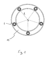
- said space is occupied by threaded bushes 3, regularly spaced around opening 201 and placed at a radial distance R from the centre of the same (see fig. 2 ).
- fig. 2 shows a counter-flange comprising 5 threaded bushes 3.
- Said threaded bushes 3 are fixed and constrained to said abutment wall 1203 through known plastic deformation techniques, such as riveting and/or calking. According to a preferred embodiment of the invention, moreover, said threaded bushes 3 are directly applied during the (cold) moulding of counter-flange 12, by special in se known equipment.
- Holes 1101 are therefore obtained on said flange 11, as per prior art, for the insertion and passage of the threaded stems 401 of said tightening screws 4.
- Said holes 1101 are arranged along circumferences with a radius equal to said radial distance R and spaced from each other like the corresponding threaded bushes 3.
- flange 11 and the sealing ring 13 are centred relative to counter-flange 12; more in particular, holes 1101 of flange 11 are interfaced and centred on the threaded bushes 3, whereas faces 1301, 1302 and 1303 of the sealing ring 13 are carried and kept in abutment respectively on shoulder 1202 of counter-flange 12 and on surfaces 1102 and 1103 of flange 11 (see fig. 1 ).
- the tightening screws 4 are then inserted through holes 1101 of flange 11 and then they are tightened on the threaded bushes 3 (for example by known automatic equipment and up to move the neck 403 thereof in abutment on the top surface of flange 11), which have certain position.
- said tightening squeezes the sealing ring 13 between flange 11 and the surface of cap 2, up to a fixed compression and such as to ensure an effective seal between interior and exterior of the water heater and, at the same time, it ensures a high mechanical resistance and excellent reliability (also at much higher pressures than the operating ones of the water heater) of the flange-counter-flange coupling.
- the main advantage of the flanging unit 1 of the storage water heater according to the invention is that of a quicker and easier assembly of flange 11 on counter-flange 12, as it is sufficient to just tighten screw 4 on the respective threaded bush 3, already arranged in counter-flange 12.
- the entire assembly process of the flanging unit 1 becomes easily automated and requires less labour, therefore being able to direct at least a part of the operators in charge of assembly to other activities.
Landscapes
- Engineering & Computer Science (AREA)
- Physics & Mathematics (AREA)
- Thermal Sciences (AREA)
- Chemical & Material Sciences (AREA)
- Combustion & Propulsion (AREA)
- Mechanical Engineering (AREA)
- General Engineering & Computer Science (AREA)
- Heat-Pump Type And Storage Water Heaters (AREA)
- Lining Or Joining Of Plastics Or The Like (AREA)
- Resistance Heating (AREA)
- Gasket Seals (AREA)
- Water Treatment By Sorption (AREA)
Description
- The present invention relates to a flanging unit especially but non-exclusively suitable for being used on thermo-sanitary fixtures.
- More in particular, the aim of the present invention is a storage water heater comprising a flanging unit of the type comprising a flange and a counter-flange which can be tightened against each other.
- As known, storage water heaters comprise a cylindrical portion, called "ferrule", closed by two caps; an opening is obtained on one of said caps for the introduction and passage of at least the sheath of a thermostat (containing one or more temperature sensors), anticorrosion devices, and optionally one or more electrical resistance (in the case of electrical storage water heaters); such components are generally mounted on a flange that also serves as closure for said opening. As known, the flange is tightened on an annular counter-flange, welded to the cap at its outer edge; the inner edge of the counter-flange, on the other hand, is generally constrained to the edge of the cap opening by, for example, a bend.
- A sealing element, made of an elastic material, interposed between flange and cap, ensures the hermetic seal between the water heater interior and exterior.
- According to a widely used flanging unit very popular for several years (see, for example,
document IT 1 305 508 fig. 2 of the above document) and through corresponding holes of the flange. Respective tightening nuts are screwed on said stems up to move them in abutment on the flange itself. The tightening of such nuts squeezes the sealing element between flange and cap (substantially at its opening) so as to obtain a hermetic seal. - According to the embodiment described and shown in the document
DE 37 25 219 disclosing the preamble ofclaim 1, said nuts, on which said screws are tightened, should be already welded on the flanging unit. - In both case, the operations for assembling such flanging unit are particularly and disadvantageously long and complicated, for example due to a difficult automation and speeding up thereof.
- In fact, as known, after having obtained said counter-flange by moulding and after the fixing thereof, as already briefly described, to the relevant cap, it is necessary to use at least a first operator, along the assembly line, to introduce the tightening screws into the slots of the counter-flange and at least a second operator intended for centring and inserting the flange on the threaded stems of said screws. The second operator, moreover, places also the nuts that will be finally tightened by a third operator on said stems.
- It is clear that at present, such assembly requires an excessive use of labour with negative consequences on production times and costs.
- The same slots of the counter-flange have quite a complex and articulated shape, required for the particular insertion of heads and stems of the tightening screws, the latter being an operation not always quick and immediate.
- Moreover, the shape of said slots gives an uncertain position to the tightening screws that forces to use the operators for both inserting said tightening screws and for applying flange and nuts.
- To this end, and for a more detailed knowledge of the flanging unit briefly described so far, reference shall be made again to document
IT 1 305 508 - The same bend of the opening on the cap for fixing the counter-flange, requires specialised personnel and an additional operation that extend time and costs for manufacturing the water heater as a whole.
- At the same time, the technique of welding described in the documents
DE 37 25 219 and/or in the publication "Maschinenelemente, Band I, Konstruktion und Berechnung von Verbindungen, Lagern und Wellen" in the name of G. Niemann seems to prevent a rapid disassembly of the flanging unit (e.g., for replacement and/or maintenance) from a storage water heater. - The aim of the present finding is to obviate at least a part of the drawbacks described above.
- In particular, the main aim of the present invention is to obtain a storage water heater comprising an improved flanging unit that should allow an easy, convenient and quick assembly process thereof.
- A second aim of the present invention is to provide a storage water heater comprising an improved flanging unit inexpensive to make and assemble.
- A third aim of the present invention is to provide a storage water heater comprising an improved flanging unit capable of ensuring a certain position of the components thereof, allowing the assembly thereof with known automatic machines.
- A further aim of the present invention is to obtain a storage water heater comprising an improved and simplified flanging unit which should ensure mechanical resistance, reliability and precision of the flange-counter-flange coupling similar to the flanging systems according to the prior art.
- These and other aims, which shall appear clearly hereinafter, are achieved with a storage water heater comprising a flanging unit according to
claim 1. - Further features of this invention will appear more clearly from the following description of a preferred embodiment thereof, according to the patent claims and illustrated, by way of a non-limiting example, in the annexed drawings, wherein:
-
figure 1 shows a side cross-section view of the flanging unit as a whole, according to the invention; -
figure 2 shows a plan view of the counter-flange of the flanging unit according to the invention. - With reference to
fig. 1 ,reference numeral 1 globally denotes the flanging unit according to the invention. - More in particular,
fig. 1 only shows a cap 2 (in particular,cap 2 of a storage water heater arranged with vertical axis) of a storage water heater, for simplicity, whereon anopening 201 is made for introducing, as known, the sheath of a thermostat (containing one or more temperature sensors), anticorrosion devices and a group of heating elements (electrical resistors, in the case of electrical storage water heaters), not shown in the attached figures and hereinafter globally indicated as cheating and safety unit. -
Reference numeral 202, moreover, denotes the inlet conduit for the cold water into the storage water heater, throughcap 2 itself. - At said opening 201 there is positioned and fixed the
flanging unit 1 of the storage water heater according to the invention. - As known, the
flanging unit 1 comprises a flange 11, suitable for supporting said heating and safety unit , and acounter-flange 12 whereon, as will be seen, flange 11 itself is tightened. - Flange 11 also serves for closing opening 201 of
cap 2. -
Reference numeral 13, moreover, denotes a sealing element, for example a ring made of an elastic material, interposed between flange 11 and the surface ofcap 2, substantially at the edge ofopening 201 thereof. - Even more in particular,
counter-flange 12 preferably has an annular shape and exhibits a substantially C-shaped section. -
Counter-flange 12 therefore comprises anouter edge 1201 welded by projection or condenser discharge (or by other known welding or gluing techniques) tocap 2 and aninner edge 1202, simply resting on the same in the proximity ofopening 201; theinner edge 1202 therefore simply serves as shoulder (hereinafter shoulder 1202) for the sealingelement 13. - An
abutment wall 1203 is located between saidouter edge 1201 andshoulder 1202. - According to the prior art (see
document IT 1 305 508 cap 2 and theabutment wall 1203 ofcounter-flange 12. The threaded stems of said screws pass through shaped openings obtained on saidabutment surface 1203 and the nuts for the final tightening of flange 11 (also pierced and crossed by said stems) oncounter-flange 12 are screwed thereon. According to the invention, on the other hand, said space is occupied by threadedbushes 3, regularly spaced around opening 201 and placed at a radial distance R from the centre of the same (seefig. 2 ). For example,fig. 2 shows a counter-flange comprising 5 threadedbushes 3. - Said threaded
bushes 3 are fixed and constrained to saidabutment wall 1203 through known plastic deformation techniques, such as riveting and/or calking. According to a preferred embodiment of the invention, moreover, said threadedbushes 3 are directly applied during the (cold) moulding ofcounter-flange 12, by special in se known equipment. - The tightening screws 4 (of head 402) will then be screwed on said threaded
bushes 3 for tightening flange 11 oncounter-flange 12. -
Holes 1101 are therefore obtained on said flange 11, as per prior art, for the insertion and passage of the threadedstems 401 of said tighteningscrews 4. - Said
holes 1101 are arranged along circumferences with a radius equal to said radial distance R and spaced from each other like the corresponding threadedbushes 3. - At this point it is possible to briefly describe the process for fixing the
flanging unit 1 of the storage water heater according to the invention. - After moulding the counter-flange 12 (that according to the invention is already provided with bushes 3) and the subsequent welding to cap 2 (as described), flange 11 and the
sealing ring 13 are centred relative tocounter-flange 12; more in particular,holes 1101 of flange 11 are interfaced and centred on the threadedbushes 3, whereasfaces sealing ring 13 are carried and kept in abutment respectively onshoulder 1202 ofcounter-flange 12 and onsurfaces fig. 1 ). - The tightening
screws 4 are then inserted throughholes 1101 of flange 11 and then they are tightened on the threaded bushes 3 (for example by known automatic equipment and up to move theneck 403 thereof in abutment on the top surface of flange 11), which have certain position. - As mentioned, said tightening squeezes the sealing
ring 13 between flange 11 and the surface ofcap 2, up to a fixed compression and such as to ensure an effective seal between interior and exterior of the water heater and, at the same time, it ensures a high mechanical resistance and excellent reliability (also at much higher pressures than the operating ones of the water heater) of the flange-counter-flange coupling. - It is therefore clear that with the
flanging unit 1 described above the intended aims are achieved. - In particular, the main advantage of the
flanging unit 1 of the storage water heater according to the invention is that of a quicker and easier assembly of flange 11 oncounter-flange 12, as it is sufficient to just tightenscrew 4 on the respective threadedbush 3, already arranged incounter-flange 12. - Actually, compared to the prior art, the use of the tightening nuts (and of the relevant washers), tightened, as known, on the stem of special screws manually positioned, not without effort, on shaped slots of the counter-flange, is eliminated.
- Thanks to the certain position of
components flanging unit 1 becomes easily automated and requires less labour, therefore being able to direct at least a part of the operators in charge of assembly to other activities. - Also eliminating one or more elements of the flanging unit 1 (nuts and washers, in particular), the reduction of assembly time and labour required for it lead to a considerable reduction of costs.
Claims (5)
- Storage water heater comprising a flanging unit (1) placed in the proximity of an opening (201) obtained at least on a cap (2) of said storage water heater, and comprising:- a flange (11) for supporting a heating and safety unit and suitable for closing said opening (201),- a counter-flange (12) stiffly constrained on said cap (2),- a sealing element (13) interposed between said flange (11) and the outer surface of said cap (2),said flange (11) and counter-flange (12) being able to be tightened against each other through a plurality of tightening screws (4) in turn comprising at least one head (402) and a threaded stem (401), characterised in that
said threaded stem (401) of said tightening screws (4) is able to be screwed on respective threaded bushes (3) placed and constrained on said counter-flange (12) by plastic deformation. - Storage water heater comprising a flanging unit (1) according to the previous claim
characterised in that
said threaded bushes (3) are seated between said cap (2) and an abutment wall (1203) of said counter-flange (12), said abutment wall (1203), whereon said threaded bushes (3) are constrained by plastic deformation, being comprised between an outer edge (1201) and an inner edge (1202) of said counter-flange (12). - Storage water heater comprising a flanging unit (1) according to the previous claim
characterised in that
said threaded bushes (3) are riveted on said abutment wall (1203). - Storage water heater comprising a flanging unit (1) according to any of the claims 2 to 3
characterised in that
said outer edge (1201) of said counter-flange (12) is fixed to the cap (2) by welding. - Storage water heater comprising a flanging unit (1) according to any of the claims 2 to 4
characterised in that
said sealing element (13) is a ring made of an elastic material, said sealing ring (13) having a face (1301) placed in abutment on the inner edge (1202) of said counter-flange (12) and a first face (1302) and a second face (1303) respectively in abutment on the corresponding first surface (1102) and second surface (1103) of said flange (11).
Applications Claiming Priority (2)
| Application Number | Priority Date | Filing Date | Title |
|---|---|---|---|
| ITAN20080025 ITAN20080025U1 (en) | 2008-12-22 | 2008-12-22 | FLANGING UNIT FOR WATER HEATER WITH ACCUMULATION |
| PCT/IB2009/007814 WO2010073088A2 (en) | 2008-12-22 | 2009-12-14 | Flanging unit for storage water heater |
Publications (2)
| Publication Number | Publication Date |
|---|---|
| EP2368077A2 EP2368077A2 (en) | 2011-09-28 |
| EP2368077B1 true EP2368077B1 (en) | 2015-08-26 |
Family
ID=42288190
Family Applications (1)
| Application Number | Title | Priority Date | Filing Date |
|---|---|---|---|
| EP09798955.2A Active EP2368077B1 (en) | 2008-12-22 | 2009-12-14 | Flanging unit for storage water heater |
Country Status (4)
| Country | Link |
|---|---|
| EP (1) | EP2368077B1 (en) |
| IT (1) | ITAN20080025U1 (en) |
| RU (1) | RU2505753C2 (en) |
| WO (1) | WO2010073088A2 (en) |
Cited By (1)
| Publication number | Priority date | Publication date | Assignee | Title |
|---|---|---|---|---|
| CN106225220A (en) * | 2016-07-19 | 2016-12-14 | 宁波帅康热水器有限公司 | A kind of high waterproof thermal-insulated fire-retardant electric heater |
Families Citing this family (1)
| Publication number | Priority date | Publication date | Assignee | Title |
|---|---|---|---|---|
| JP6321348B2 (en) * | 2013-10-15 | 2018-05-09 | 株式会社Lixil | Hot water storage tank |
Family Cites Families (8)
| Publication number | Priority date | Publication date | Assignee | Title |
|---|---|---|---|---|
| DE1299832B (en) * | 1965-05-03 | 1969-07-24 | Siemens Elektrogeraete Gmbh | Hot water device, especially boiling water device |
| SU1115896A1 (en) * | 1983-05-27 | 1984-09-30 | Dekalchuk Aleksandr A | Device for tightening threaded joints |
| DE3623139A1 (en) * | 1985-09-20 | 1988-01-21 | Stiebel Eltron Gmbh & Co Kg | Receptacle with a flange |
| DE3725219C3 (en) * | 1987-07-30 | 1995-04-20 | Vaillant Joh Gmbh & Co | Flange mounting |
| SU1765599A1 (en) * | 1989-04-27 | 1992-09-30 | Всесоюзный Научно-Исследовательский И Проектно-Технологический Институт Нефтяного Машиностроения | Flange connection |
| AT402669B (en) * | 1991-02-14 | 1997-07-25 | Vaillant Gmbh | STORAGE CONTAINER STORAGE CONTAINER |
| RU2120584C1 (en) * | 1996-07-11 | 1998-10-20 | Радченко Сергей Анатольевич | Water heater |
| IT1305508B1 (en) | 1998-07-24 | 2001-05-09 | Merloni Termosanitari Spa | FLANGING SYSTEM WITH DEVICE AGAINST THE LEAKAGE OF THE FIXING SCREWS |
-
2008
- 2008-12-22 IT ITAN20080025 patent/ITAN20080025U1/en unknown
-
2009
- 2009-12-14 EP EP09798955.2A patent/EP2368077B1/en active Active
- 2009-12-14 RU RU2011130187/06A patent/RU2505753C2/en active
- 2009-12-14 WO PCT/IB2009/007814 patent/WO2010073088A2/en not_active Ceased
Cited By (2)
| Publication number | Priority date | Publication date | Assignee | Title |
|---|---|---|---|---|
| CN106225220A (en) * | 2016-07-19 | 2016-12-14 | 宁波帅康热水器有限公司 | A kind of high waterproof thermal-insulated fire-retardant electric heater |
| CN106225220B (en) * | 2016-07-19 | 2019-02-05 | 宁波帅康热水器有限公司 | A kind of high waterproof thermal-insulated fire-retardant electric heater |
Also Published As
| Publication number | Publication date |
|---|---|
| RU2505753C2 (en) | 2014-01-27 |
| WO2010073088A3 (en) | 2012-11-29 |
| WO2010073088A2 (en) | 2010-07-01 |
| EP2368077A2 (en) | 2011-09-28 |
| ITAN20080025U1 (en) | 2010-06-23 |
| RU2011130187A (en) | 2013-01-27 |
Similar Documents
| Publication | Publication Date | Title |
|---|---|---|
| US7481462B2 (en) | Flange connection for pipes | |
| EP2677223B1 (en) | Fitting for connecting pipes, in particular flexible pipes | |
| EP3143355B1 (en) | Radiator element provided with a hooked closing cap and radiator thereof | |
| JPS5930959B2 (en) | drain plug combination | |
| KR101177674B1 (en) | Tubing conjunction structure for water purifying path | |
| US9938856B2 (en) | Tool for fitting an inner bearing race carrying a bearing cage and screws for retaining in a turbomachine | |
| US9470318B2 (en) | Eccentric valve and manufacturing method thereof | |
| KR101185176B1 (en) | Valve connection device | |
| EP2459950B1 (en) | Heating radiator element and method and device for closing an end part of a heating radiator element | |
| EP2368077A2 (en) | Flanging unit for storage water heater | |
| US10018309B2 (en) | Control head of a fluid measuring device, fluid measuring device, and method of manufacturing a control head | |
| US5748689A (en) | Sealing device for an instrumentation column penetrating the head of the vessel of a nuclear reactor inside an adapter | |
| EP3429814B1 (en) | Method for assembling a female mould and female mould arrangement | |
| KR20170030621A (en) | Compression seal having an elastomer body | |
| WO2016065418A1 (en) | Hot water storage device | |
| EP1923353A1 (en) | Filter cartridge assembly | |
| US20170009436A1 (en) | Intermediate holder | |
| EP2387647B1 (en) | Drain valve assembly | |
| JP4280151B2 (en) | Corrosion resistant valve | |
| US20170248235A1 (en) | Mechanical seal device | |
| US20180223507A1 (en) | Hydrant stem coupling with ribs | |
| AU644239B2 (en) | Improvements in tapping bands | |
| US11906066B2 (en) | Seal support ring for a valve | |
| US11054073B2 (en) | Hose barb retention device | |
| CN211224841U (en) | Punching end socket |
Legal Events
| Date | Code | Title | Description |
|---|---|---|---|
| PUAI | Public reference made under article 153(3) epc to a published international application that has entered the european phase |
Free format text: ORIGINAL CODE: 0009012 |
|
| 17P | Request for examination filed |
Effective date: 20110530 |
|
| AK | Designated contracting states |
Kind code of ref document: A2 Designated state(s): AT BE BG CH CY CZ DE DK EE ES FI FR GB GR HR HU IE IS IT LI LT LU LV MC MK MT NL NO PL PT RO SE SI SK SM TR |
|
| DAX | Request for extension of the european patent (deleted) | ||
| R17D | Deferred search report published (corrected) |
Effective date: 20121129 |
|
| 17Q | First examination report despatched |
Effective date: 20140605 |
|
| GRAP | Despatch of communication of intention to grant a patent |
Free format text: ORIGINAL CODE: EPIDOSNIGR1 |
|
| INTG | Intention to grant announced |
Effective date: 20150414 |
|
| RIN1 | Information on inventor provided before grant (corrected) |
Inventor name: TONINI, RAFFAELE Inventor name: FERRONI, STEFANO Inventor name: BIAGIOLI, EVANDRO Inventor name: LATINI, LUCIO |
|
| GRAS | Grant fee paid |
Free format text: ORIGINAL CODE: EPIDOSNIGR3 |
|
| GRAA | (expected) grant |
Free format text: ORIGINAL CODE: 0009210 |
|
| AK | Designated contracting states |
Kind code of ref document: B1 Designated state(s): AT BE BG CH CY CZ DE DK EE ES FI FR GB GR HR HU IE IS IT LI LT LU LV MC MK MT NL NO PL PT RO SE SI SK SM TR |
|
| REG | Reference to a national code |
Ref country code: GB Ref legal event code: FG4D |
|
| REG | Reference to a national code |
Ref country code: CH Ref legal event code: EP |
|
| REG | Reference to a national code |
Ref country code: AT Ref legal event code: REF Ref document number: 745424 Country of ref document: AT Kind code of ref document: T Effective date: 20150915 |
|
| REG | Reference to a national code |
Ref country code: IE Ref legal event code: FG4D |
|
| REG | Reference to a national code |
Ref country code: DE Ref legal event code: R096 Ref document number: 602009033224 Country of ref document: DE |
|
| REG | Reference to a national code |
Ref country code: FR Ref legal event code: PLFP Year of fee payment: 7 |
|
| REG | Reference to a national code |
Ref country code: AT Ref legal event code: MK05 Ref document number: 745424 Country of ref document: AT Kind code of ref document: T Effective date: 20150826 |
|
| REG | Reference to a national code |
Ref country code: LT Ref legal event code: MG4D |
|
| PG25 | Lapsed in a contracting state [announced via postgrant information from national office to epo] |
Ref country code: GR Free format text: LAPSE BECAUSE OF FAILURE TO SUBMIT A TRANSLATION OF THE DESCRIPTION OR TO PAY THE FEE WITHIN THE PRESCRIBED TIME-LIMIT Effective date: 20151127 Ref country code: NO Free format text: LAPSE BECAUSE OF FAILURE TO SUBMIT A TRANSLATION OF THE DESCRIPTION OR TO PAY THE FEE WITHIN THE PRESCRIBED TIME-LIMIT Effective date: 20151126 Ref country code: LV Free format text: LAPSE BECAUSE OF FAILURE TO SUBMIT A TRANSLATION OF THE DESCRIPTION OR TO PAY THE FEE WITHIN THE PRESCRIBED TIME-LIMIT Effective date: 20150826 Ref country code: LT Free format text: LAPSE BECAUSE OF FAILURE TO SUBMIT A TRANSLATION OF THE DESCRIPTION OR TO PAY THE FEE WITHIN THE PRESCRIBED TIME-LIMIT Effective date: 20150826 Ref country code: FI Free format text: LAPSE BECAUSE OF FAILURE TO SUBMIT A TRANSLATION OF THE DESCRIPTION OR TO PAY THE FEE WITHIN THE PRESCRIBED TIME-LIMIT Effective date: 20150826 |
|
| REG | Reference to a national code |
Ref country code: NL Ref legal event code: MP Effective date: 20150826 |
|
| PG25 | Lapsed in a contracting state [announced via postgrant information from national office to epo] |
Ref country code: AT Free format text: LAPSE BECAUSE OF FAILURE TO SUBMIT A TRANSLATION OF THE DESCRIPTION OR TO PAY THE FEE WITHIN THE PRESCRIBED TIME-LIMIT Effective date: 20150826 Ref country code: ES Free format text: LAPSE BECAUSE OF FAILURE TO SUBMIT A TRANSLATION OF THE DESCRIPTION OR TO PAY THE FEE WITHIN THE PRESCRIBED TIME-LIMIT Effective date: 20150826 Ref country code: IS Free format text: LAPSE BECAUSE OF FAILURE TO SUBMIT A TRANSLATION OF THE DESCRIPTION OR TO PAY THE FEE WITHIN THE PRESCRIBED TIME-LIMIT Effective date: 20151226 Ref country code: HR Free format text: LAPSE BECAUSE OF FAILURE TO SUBMIT A TRANSLATION OF THE DESCRIPTION OR TO PAY THE FEE WITHIN THE PRESCRIBED TIME-LIMIT Effective date: 20150826 Ref country code: SE Free format text: LAPSE BECAUSE OF FAILURE TO SUBMIT A TRANSLATION OF THE DESCRIPTION OR TO PAY THE FEE WITHIN THE PRESCRIBED TIME-LIMIT Effective date: 20150826 Ref country code: PL Free format text: LAPSE BECAUSE OF FAILURE TO SUBMIT A TRANSLATION OF THE DESCRIPTION OR TO PAY THE FEE WITHIN THE PRESCRIBED TIME-LIMIT Effective date: 20150826 Ref country code: PT Free format text: LAPSE BECAUSE OF FAILURE TO SUBMIT A TRANSLATION OF THE DESCRIPTION OR TO PAY THE FEE WITHIN THE PRESCRIBED TIME-LIMIT Effective date: 20151228 |
|
| PG25 | Lapsed in a contracting state [announced via postgrant information from national office to epo] |
Ref country code: NL Free format text: LAPSE BECAUSE OF FAILURE TO SUBMIT A TRANSLATION OF THE DESCRIPTION OR TO PAY THE FEE WITHIN THE PRESCRIBED TIME-LIMIT Effective date: 20150826 |
|
| PG25 | Lapsed in a contracting state [announced via postgrant information from national office to epo] |
Ref country code: DK Free format text: LAPSE BECAUSE OF FAILURE TO SUBMIT A TRANSLATION OF THE DESCRIPTION OR TO PAY THE FEE WITHIN THE PRESCRIBED TIME-LIMIT Effective date: 20150826 Ref country code: CZ Free format text: LAPSE BECAUSE OF FAILURE TO SUBMIT A TRANSLATION OF THE DESCRIPTION OR TO PAY THE FEE WITHIN THE PRESCRIBED TIME-LIMIT Effective date: 20150826 Ref country code: EE Free format text: LAPSE BECAUSE OF FAILURE TO SUBMIT A TRANSLATION OF THE DESCRIPTION OR TO PAY THE FEE WITHIN THE PRESCRIBED TIME-LIMIT Effective date: 20150826 Ref country code: SK Free format text: LAPSE BECAUSE OF FAILURE TO SUBMIT A TRANSLATION OF THE DESCRIPTION OR TO PAY THE FEE WITHIN THE PRESCRIBED TIME-LIMIT Effective date: 20150826 |
|
| REG | Reference to a national code |
Ref country code: DE Ref legal event code: R097 Ref document number: 602009033224 Country of ref document: DE |
|
| PG25 | Lapsed in a contracting state [announced via postgrant information from national office to epo] |
Ref country code: RO Free format text: LAPSE BECAUSE OF FAILURE TO SUBMIT A TRANSLATION OF THE DESCRIPTION OR TO PAY THE FEE WITHIN THE PRESCRIBED TIME-LIMIT Effective date: 20150826 |
|
| PLBE | No opposition filed within time limit |
Free format text: ORIGINAL CODE: 0009261 |
|
| STAA | Information on the status of an ep patent application or granted ep patent |
Free format text: STATUS: NO OPPOSITION FILED WITHIN TIME LIMIT |
|
| PG25 | Lapsed in a contracting state [announced via postgrant information from national office to epo] |
Ref country code: MC Free format text: LAPSE BECAUSE OF FAILURE TO SUBMIT A TRANSLATION OF THE DESCRIPTION OR TO PAY THE FEE WITHIN THE PRESCRIBED TIME-LIMIT Effective date: 20150826 Ref country code: LU Free format text: LAPSE BECAUSE OF FAILURE TO SUBMIT A TRANSLATION OF THE DESCRIPTION OR TO PAY THE FEE WITHIN THE PRESCRIBED TIME-LIMIT Effective date: 20151214 |
|
| REG | Reference to a national code |
Ref country code: CH Ref legal event code: PL |
|
| 26N | No opposition filed |
Effective date: 20160530 |
|
| GBPC | Gb: european patent ceased through non-payment of renewal fee |
Effective date: 20151214 |
|
| PG25 | Lapsed in a contracting state [announced via postgrant information from national office to epo] |
Ref country code: SI Free format text: LAPSE BECAUSE OF FAILURE TO SUBMIT A TRANSLATION OF THE DESCRIPTION OR TO PAY THE FEE WITHIN THE PRESCRIBED TIME-LIMIT Effective date: 20150826 |
|
| REG | Reference to a national code |
Ref country code: IE Ref legal event code: MM4A |
|
| PG25 | Lapsed in a contracting state [announced via postgrant information from national office to epo] |
Ref country code: IE Free format text: LAPSE BECAUSE OF NON-PAYMENT OF DUE FEES Effective date: 20151214 Ref country code: GB Free format text: LAPSE BECAUSE OF NON-PAYMENT OF DUE FEES Effective date: 20151214 Ref country code: CH Free format text: LAPSE BECAUSE OF NON-PAYMENT OF DUE FEES Effective date: 20151231 Ref country code: LI Free format text: LAPSE BECAUSE OF NON-PAYMENT OF DUE FEES Effective date: 20151231 |
|
| REG | Reference to a national code |
Ref country code: FR Ref legal event code: PLFP Year of fee payment: 8 |
|
| PG25 | Lapsed in a contracting state [announced via postgrant information from national office to epo] |
Ref country code: BG Free format text: LAPSE BECAUSE OF FAILURE TO SUBMIT A TRANSLATION OF THE DESCRIPTION OR TO PAY THE FEE WITHIN THE PRESCRIBED TIME-LIMIT Effective date: 20150826 Ref country code: SM Free format text: LAPSE BECAUSE OF FAILURE TO SUBMIT A TRANSLATION OF THE DESCRIPTION OR TO PAY THE FEE WITHIN THE PRESCRIBED TIME-LIMIT Effective date: 20150826 Ref country code: HU Free format text: LAPSE BECAUSE OF FAILURE TO SUBMIT A TRANSLATION OF THE DESCRIPTION OR TO PAY THE FEE WITHIN THE PRESCRIBED TIME-LIMIT; INVALID AB INITIO Effective date: 20091214 |
|
| PG25 | Lapsed in a contracting state [announced via postgrant information from national office to epo] |
Ref country code: CY Free format text: LAPSE BECAUSE OF FAILURE TO SUBMIT A TRANSLATION OF THE DESCRIPTION OR TO PAY THE FEE WITHIN THE PRESCRIBED TIME-LIMIT Effective date: 20150826 |
|
| PG25 | Lapsed in a contracting state [announced via postgrant information from national office to epo] |
Ref country code: TR Free format text: LAPSE BECAUSE OF FAILURE TO SUBMIT A TRANSLATION OF THE DESCRIPTION OR TO PAY THE FEE WITHIN THE PRESCRIBED TIME-LIMIT Effective date: 20150826 Ref country code: MT Free format text: LAPSE BECAUSE OF FAILURE TO SUBMIT A TRANSLATION OF THE DESCRIPTION OR TO PAY THE FEE WITHIN THE PRESCRIBED TIME-LIMIT Effective date: 20150826 |
|
| REG | Reference to a national code |
Ref country code: FR Ref legal event code: PLFP Year of fee payment: 9 |
|
| PG25 | Lapsed in a contracting state [announced via postgrant information from national office to epo] |
Ref country code: MK Free format text: LAPSE BECAUSE OF FAILURE TO SUBMIT A TRANSLATION OF THE DESCRIPTION OR TO PAY THE FEE WITHIN THE PRESCRIBED TIME-LIMIT Effective date: 20150826 |
|
| REG | Reference to a national code |
Ref country code: DE Ref legal event code: R081 Ref document number: 602009033224 Country of ref document: DE Owner name: ARISTON S.P.A., FABRIANO, IT Free format text: FORMER OWNER: ARISTON THERMO S.P.A., FABRIANO, ANCONA, IT Ref country code: DE Ref legal event code: R082 Ref document number: 602009033224 Country of ref document: DE Representative=s name: SAMSON & PARTNER PATENTANWAELTE MBB, DE Ref country code: DE Ref legal event code: R081 Ref document number: 602009033224 Country of ref document: DE Owner name: ARISTON THERMO S.P.A., FABRIANO, IT Free format text: FORMER OWNER: ARISTON THERMO S.P.A., FABRIANO, ANCONA, IT |
|
| REG | Reference to a national code |
Ref country code: BE Ref legal event code: PD Owner name: ARISTON THERMO S.P.A.; IT Free format text: DETAILS ASSIGNMENT: CHANGE OF OWNER(S), ASSIGNMENT; FORMER OWNER NAME: ARISTON THERMO HOLDING S.P.A. Effective date: 20210628 Ref country code: BE Ref legal event code: HC Owner name: ARISTON THERMO HOLDING S.P.A.; IT Free format text: DETAILS ASSIGNMENT: CHANGE OF OWNER(S), CHANGE OF OWNER(S) NAME; FORMER OWNER NAME: ARISTON THERMO S.P.A. Effective date: 20210628 |
|
| REG | Reference to a national code |
Ref country code: DE Ref legal event code: R081 Ref document number: 602009033224 Country of ref document: DE Owner name: ARISTON S.P.A., FABRIANO, IT Free format text: FORMER OWNER: ARISTON THERMO S.P.A., FABRIANO, ANCONA, IT |
|
| REG | Reference to a national code |
Ref country code: BE Ref legal event code: HC Owner name: ARISTON S.P.A.; IT Free format text: DETAILS ASSIGNMENT: CHANGE OF OWNER(S), CHANGE OF OWNER(S) NAME; FORMER OWNER NAME: ARISTON THERMO S.P.A. Effective date: 20220824 |
|
| P01 | Opt-out of the competence of the unified patent court (upc) registered |
Effective date: 20230515 |
|
| PGFP | Annual fee paid to national office [announced via postgrant information from national office to epo] |
Ref country code: IT Payment date: 20241218 Year of fee payment: 17 |
|
| PGFP | Annual fee paid to national office [announced via postgrant information from national office to epo] |
Ref country code: FR Payment date: 20251121 Year of fee payment: 17 |
|
| PGFP | Annual fee paid to national office [announced via postgrant information from national office to epo] |
Ref country code: BE Payment date: 20251229 Year of fee payment: 17 |
|
| PGFP | Annual fee paid to national office [announced via postgrant information from national office to epo] |
Ref country code: DE Payment date: 20251222 Year of fee payment: 17 |