EP2367616B1 - Slurry bubble column reactor - Google Patents
Slurry bubble column reactor Download PDFInfo
- Publication number
- EP2367616B1 EP2367616B1 EP09756343.1A EP09756343A EP2367616B1 EP 2367616 B1 EP2367616 B1 EP 2367616B1 EP 09756343 A EP09756343 A EP 09756343A EP 2367616 B1 EP2367616 B1 EP 2367616B1
- Authority
- EP
- European Patent Office
- Prior art keywords
- tube
- reactor
- gas
- gas distributor
- distributor
- Prior art date
- Legal status (The legal status is an assumption and is not a legal conclusion. Google has not performed a legal analysis and makes no representation as to the accuracy of the status listed.)
- Not-in-force
Links
- 239000002002 slurry Substances 0.000 title claims description 34
- 239000003054 catalyst Substances 0.000 claims description 15
- 238000006243 chemical reaction Methods 0.000 claims description 15
- 238000000034 method Methods 0.000 claims description 11
- 239000007788 liquid Substances 0.000 claims description 8
- 239000002245 particle Substances 0.000 claims description 8
- 239000000376 reactant Substances 0.000 claims description 8
- 239000007791 liquid phase Substances 0.000 claims description 3
- 239000011949 solid catalyst Substances 0.000 claims description 3
- 230000000630 rising effect Effects 0.000 claims description 2
- 239000000725 suspension Substances 0.000 claims description 2
- 238000010408 sweeping Methods 0.000 claims description 2
- 238000003786 synthesis reaction Methods 0.000 claims description 2
- 230000015572 biosynthetic process Effects 0.000 claims 1
- 239000007789 gas Substances 0.000 description 70
- 239000012530 fluid Substances 0.000 description 4
- 239000000047 product Substances 0.000 description 3
- 230000000694 effects Effects 0.000 description 2
- 230000003628 erosive effect Effects 0.000 description 2
- 239000007795 chemical reaction product Substances 0.000 description 1
- 238000011010 flushing procedure Methods 0.000 description 1
- 230000002706 hydrostatic effect Effects 0.000 description 1
- 239000012263 liquid product Substances 0.000 description 1
- 230000035515 penetration Effects 0.000 description 1
- 239000012071 phase Substances 0.000 description 1
- 238000012805 post-processing Methods 0.000 description 1
- 238000004062 sedimentation Methods 0.000 description 1
Images

Classifications
-
- B—PERFORMING OPERATIONS; TRANSPORTING
- B01—PHYSICAL OR CHEMICAL PROCESSES OR APPARATUS IN GENERAL
- B01J—CHEMICAL OR PHYSICAL PROCESSES, e.g. CATALYSIS OR COLLOID CHEMISTRY; THEIR RELEVANT APPARATUS
- B01J8/00—Chemical or physical processes in general, conducted in the presence of fluids and solid particles; Apparatus for such processes
- B01J8/18—Chemical or physical processes in general, conducted in the presence of fluids and solid particles; Apparatus for such processes with fluidised particles
- B01J8/20—Chemical or physical processes in general, conducted in the presence of fluids and solid particles; Apparatus for such processes with fluidised particles with liquid as a fluidising medium
- B01J8/22—Chemical or physical processes in general, conducted in the presence of fluids and solid particles; Apparatus for such processes with fluidised particles with liquid as a fluidising medium gas being introduced into the liquid
-
- B—PERFORMING OPERATIONS; TRANSPORTING
- B01—PHYSICAL OR CHEMICAL PROCESSES OR APPARATUS IN GENERAL
- B01F—MIXING, e.g. DISSOLVING, EMULSIFYING OR DISPERSING
- B01F23/00—Mixing according to the phases to be mixed, e.g. dispersing or emulsifying
- B01F23/20—Mixing gases with liquids
- B01F23/23—Mixing gases with liquids by introducing gases into liquid media, e.g. for producing aerated liquids
- B01F23/231—Mixing gases with liquids by introducing gases into liquid media, e.g. for producing aerated liquids by bubbling
- B01F23/23105—Arrangement or manipulation of the gas bubbling devices
- B01F23/2312—Diffusers
- B01F23/23121—Diffusers having injection means, e.g. nozzles with circumferential outlet
-
- B—PERFORMING OPERATIONS; TRANSPORTING
- B01—PHYSICAL OR CHEMICAL PROCESSES OR APPARATUS IN GENERAL
- B01J—CHEMICAL OR PHYSICAL PROCESSES, e.g. CATALYSIS OR COLLOID CHEMISTRY; THEIR RELEVANT APPARATUS
- B01J8/00—Chemical or physical processes in general, conducted in the presence of fluids and solid particles; Apparatus for such processes
- B01J8/18—Chemical or physical processes in general, conducted in the presence of fluids and solid particles; Apparatus for such processes with fluidised particles
-
- B—PERFORMING OPERATIONS; TRANSPORTING
- B01—PHYSICAL OR CHEMICAL PROCESSES OR APPARATUS IN GENERAL
- B01F—MIXING, e.g. DISSOLVING, EMULSIFYING OR DISPERSING
- B01F33/00—Other mixers; Mixing plants; Combinations of mixers
- B01F33/40—Mixers using gas or liquid agitation, e.g. with air supply tubes
- B01F33/406—Mixers using gas or liquid agitation, e.g. with air supply tubes in receptacles with gas supply only at the bottom
- B01F33/4062—Mixers using gas or liquid agitation, e.g. with air supply tubes in receptacles with gas supply only at the bottom with means for modifying the gas pressure or for supplying gas at different pressures or in different volumes at different parts of the bottom
-
- B—PERFORMING OPERATIONS; TRANSPORTING
- B01—PHYSICAL OR CHEMICAL PROCESSES OR APPARATUS IN GENERAL
- B01J—CHEMICAL OR PHYSICAL PROCESSES, e.g. CATALYSIS OR COLLOID CHEMISTRY; THEIR RELEVANT APPARATUS
- B01J19/00—Chemical, physical or physico-chemical processes in general; Their relevant apparatus
- B01J19/24—Stationary reactors without moving elements inside
- B01J19/2455—Stationary reactors without moving elements inside provoking a loop type movement of the reactants
- B01J19/246—Stationary reactors without moving elements inside provoking a loop type movement of the reactants internally, i.e. the mixture circulating inside the vessel such that the upward stream is separated physically from the downward stream(s)
-
- B—PERFORMING OPERATIONS; TRANSPORTING
- B01—PHYSICAL OR CHEMICAL PROCESSES OR APPARATUS IN GENERAL
- B01J—CHEMICAL OR PHYSICAL PROCESSES, e.g. CATALYSIS OR COLLOID CHEMISTRY; THEIR RELEVANT APPARATUS
- B01J19/00—Chemical, physical or physico-chemical processes in general; Their relevant apparatus
- B01J19/26—Nozzle-type reactors, i.e. the distribution of the initial reactants within the reactor is effected by their introduction or injection through nozzles
-
- B—PERFORMING OPERATIONS; TRANSPORTING
- B01—PHYSICAL OR CHEMICAL PROCESSES OR APPARATUS IN GENERAL
- B01J—CHEMICAL OR PHYSICAL PROCESSES, e.g. CATALYSIS OR COLLOID CHEMISTRY; THEIR RELEVANT APPARATUS
- B01J8/00—Chemical or physical processes in general, conducted in the presence of fluids and solid particles; Apparatus for such processes
- B01J8/18—Chemical or physical processes in general, conducted in the presence of fluids and solid particles; Apparatus for such processes with fluidised particles
- B01J8/1818—Feeding of the fluidising gas
-
- B—PERFORMING OPERATIONS; TRANSPORTING
- B01—PHYSICAL OR CHEMICAL PROCESSES OR APPARATUS IN GENERAL
- B01J—CHEMICAL OR PHYSICAL PROCESSES, e.g. CATALYSIS OR COLLOID CHEMISTRY; THEIR RELEVANT APPARATUS
- B01J8/00—Chemical or physical processes in general, conducted in the presence of fluids and solid particles; Apparatus for such processes
- B01J8/18—Chemical or physical processes in general, conducted in the presence of fluids and solid particles; Apparatus for such processes with fluidised particles
- B01J8/20—Chemical or physical processes in general, conducted in the presence of fluids and solid particles; Apparatus for such processes with fluidised particles with liquid as a fluidising medium
- B01J8/22—Chemical or physical processes in general, conducted in the presence of fluids and solid particles; Apparatus for such processes with fluidised particles with liquid as a fluidising medium gas being introduced into the liquid
- B01J8/224—Chemical or physical processes in general, conducted in the presence of fluids and solid particles; Apparatus for such processes with fluidised particles with liquid as a fluidising medium gas being introduced into the liquid the particles being subject to a circulatory movement
-
- B—PERFORMING OPERATIONS; TRANSPORTING
- B01—PHYSICAL OR CHEMICAL PROCESSES OR APPARATUS IN GENERAL
- B01J—CHEMICAL OR PHYSICAL PROCESSES, e.g. CATALYSIS OR COLLOID CHEMISTRY; THEIR RELEVANT APPARATUS
- B01J8/00—Chemical or physical processes in general, conducted in the presence of fluids and solid particles; Apparatus for such processes
- B01J8/18—Chemical or physical processes in general, conducted in the presence of fluids and solid particles; Apparatus for such processes with fluidised particles
- B01J8/20—Chemical or physical processes in general, conducted in the presence of fluids and solid particles; Apparatus for such processes with fluidised particles with liquid as a fluidising medium
- B01J8/22—Chemical or physical processes in general, conducted in the presence of fluids and solid particles; Apparatus for such processes with fluidised particles with liquid as a fluidising medium gas being introduced into the liquid
- B01J8/224—Chemical or physical processes in general, conducted in the presence of fluids and solid particles; Apparatus for such processes with fluidised particles with liquid as a fluidising medium gas being introduced into the liquid the particles being subject to a circulatory movement
- B01J8/226—Chemical or physical processes in general, conducted in the presence of fluids and solid particles; Apparatus for such processes with fluidised particles with liquid as a fluidising medium gas being introduced into the liquid the particles being subject to a circulatory movement internally, i.e. the particles rotate within the vessel
-
- C—CHEMISTRY; METALLURGY
- C07—ORGANIC CHEMISTRY
- C07C—ACYCLIC OR CARBOCYCLIC COMPOUNDS
- C07C1/00—Preparation of hydrocarbons from one or more compounds, none of them being a hydrocarbon
- C07C1/02—Preparation of hydrocarbons from one or more compounds, none of them being a hydrocarbon from oxides of a carbon
- C07C1/04—Preparation of hydrocarbons from one or more compounds, none of them being a hydrocarbon from oxides of a carbon from carbon monoxide with hydrogen
- C07C1/0405—Apparatus
- C07C1/041—Reactors
- C07C1/0415—Reactors with moving catalysts
-
- C—CHEMISTRY; METALLURGY
- C10—PETROLEUM, GAS OR COKE INDUSTRIES; TECHNICAL GASES CONTAINING CARBON MONOXIDE; FUELS; LUBRICANTS; PEAT
- C10G—CRACKING HYDROCARBON OILS; PRODUCTION OF LIQUID HYDROCARBON MIXTURES, e.g. BY DESTRUCTIVE HYDROGENATION, OLIGOMERISATION, POLYMERISATION; RECOVERY OF HYDROCARBON OILS FROM OIL-SHALE, OIL-SAND, OR GASES; REFINING MIXTURES MAINLY CONSISTING OF HYDROCARBONS; REFORMING OF NAPHTHA; MINERAL WAXES
- C10G2/00—Production of liquid hydrocarbon mixtures of undefined composition from oxides of carbon
-
- C—CHEMISTRY; METALLURGY
- C10—PETROLEUM, GAS OR COKE INDUSTRIES; TECHNICAL GASES CONTAINING CARBON MONOXIDE; FUELS; LUBRICANTS; PEAT
- C10G—CRACKING HYDROCARBON OILS; PRODUCTION OF LIQUID HYDROCARBON MIXTURES, e.g. BY DESTRUCTIVE HYDROGENATION, OLIGOMERISATION, POLYMERISATION; RECOVERY OF HYDROCARBON OILS FROM OIL-SHALE, OIL-SAND, OR GASES; REFINING MIXTURES MAINLY CONSISTING OF HYDROCARBONS; REFORMING OF NAPHTHA; MINERAL WAXES
- C10G2/00—Production of liquid hydrocarbon mixtures of undefined composition from oxides of carbon
- C10G2/30—Production of liquid hydrocarbon mixtures of undefined composition from oxides of carbon from carbon monoxide with hydrogen
- C10G2/32—Production of liquid hydrocarbon mixtures of undefined composition from oxides of carbon from carbon monoxide with hydrogen with the use of catalysts
- C10G2/34—Apparatus, reactors
- C10G2/342—Apparatus, reactors with moving solid catalysts
- C10G2/344—Apparatus, reactors with moving solid catalysts according to the "fluidised-bed" technique
-
- B—PERFORMING OPERATIONS; TRANSPORTING
- B01—PHYSICAL OR CHEMICAL PROCESSES OR APPARATUS IN GENERAL
- B01J—CHEMICAL OR PHYSICAL PROCESSES, e.g. CATALYSIS OR COLLOID CHEMISTRY; THEIR RELEVANT APPARATUS
- B01J2208/00—Processes carried out in the presence of solid particles; Reactors therefor
- B01J2208/00796—Details of the reactor or of the particulate material
- B01J2208/00893—Feeding means for the reactants
- B01J2208/00911—Sparger-type feeding elements
Definitions
- the present invention relates to a gas distributor arrangement in a three phase reactor or slurry bubble column reactor (SBCR).
- SBCR slurry bubble column reactor
- SBCRs are employed to conduct many chemical reactions, particularly reactions in which the reactants are gaseous, the products include liquids, and a solid catalyst is required.
- the gaseous reactants are introduced into a slurry of finely divided catalyst in a liquid medium which may contain a liquid reaction product.
- the gas introduction is achieved using a gas distributor.
- a gas distributor for a slurry bubble column should satisfy some important requirements, which include:
- a slurry bubble column reactor comprising a reactor vessel having a gas outlet and a liquid outlet, and a gas distributor arrangement in the region of the bottom of the vessel when in its orientation for use, the gas distributor arrangement comprising an upper gas distributor, a lower gas distributor spaced from the upper distributor to a position nearer the bottom of the vessel and a tube open at both ends and with its longitudinal axis extending generally vertically when the vessel is in its orientation for use, the tube being arranged so that the upper gas distributor is located close to or in the vicinity of the upper open end of the tube, and the lower gas distributor is located at a level close to the lower end of the tube, whereby in use gas from the lower sparger rings rises into the tube, reduces the density of the slurry, and causes the slurry in the tube to rise.
- a difference in density is established between the slurry outside the tube and the slurry inside the tube by means of the gas from the lower distributor entering the tube, and this in turn causes slurry outside the tube to flow downwards thereby sweeping the inside wall of the vessel, and then upwards through the tube as the gas from the lower distributor is entrained.
- the system avoids difficulties associated with control of the gas nozzle pressures brought about by having a series of gas manifolds with their respective nozzles at difference heights at the bottom of the reactor, which will then have to overcome different hydrostatic pressures.
- Independent control of the pressure to the two gas distributors means that gas can be injected through the upper gas distributor at a lower pressure than through the lower gas distributor, if desired, or even through the lower gas distributor alone.
- the upper gas distributor comprises a manifold arrangement with a plurality of upper nozzles.
- the manifold arrangement may comprise one or more pipes each having a plurality of upper nozzles.
- the manifold arrangement comprises a plurality of generally circular or part-circular concentric pipes each having a plurality of upper nozzles arranged along its length.
- the concentric pipes are tubular toroids or toroid sections.
- the upper nozzles all lie in a common generally horizontal plane, with height variations typically ⁇ 100mm.
- the diameter of the openings of the upper gas nozzles is equal to or greater than 5 mm.
- the openings of the upper nozzles are arranged so that the principal axis of the jets of gas produced has an inclination of 90° or less below horizontal.
- the upper gas distributor is connected to an upper gas supply arrangement, which gives a supply pressure to each of the nozzles with a variation between nozzle supply pressure of less than 100% of the average nozzle pressure drop.
- the lower gas distributor comprises a manifold arrangement with a plurality of lower nozzles.
- the manifold arrangement comprises one or more pipes, each having a plurality of lower nozzles.
- the manifold arrangement comprises a plurality of generally circular or part-circular concentric pipes each having a plurality of lower nozzles arranged along its length.
- the concentric pipes are tubular toroids or toroid sections.
- the lower nozzles all lie in a common generally horizontal plane, with variations typically ⁇ 100mm.
- the diameter of the openings of the lower nozzle is equal to or greater than 5mm.
- the lower gas distributor is connected to a lower gas supply arrangement, which gives a supply pressure to each of the nozzles with a variation between nozzle supply pressure of less than 100% of the average nozzle pressure drop.
- the upper and lower gas distributors together cover from 30 to 100% of the cross-sectional area of the reactor , preferably from 40 to 80%.
- the lower gas distributor represents from 2 to 12% of the cross-sectional area of the reactor, preferably from 5 to 8%.
- the lower gas distributor is arranged to supply 4 to 20% of the gas flow to the reactor, preferably from 8 to 15%.
- the tube is cylindrical and arranged generally in the reactor with its longitudinal axis substantially vertical.
- the upper gas distributor is at a position between 1m above the top of the tube and 50% of the tube length below the top of the tube.
- the lower gas distributor is between 0.3m beneath and 0.3m above the bottom of the tube.
- the cross-sectional area of this is sufficient so that the average slurry velocity through this gap is slower than 5 m/s to avoid erosion of reactor bottom and attrition of catalyst particles. The velocity should however be >0.5 m/s to avoid settling of catalyst at bottom.
- the reactor vessel is generally cylindrical but at the bottom, there is a curved portion extending from the main cylindrical wall, a part-conical portion extending from the curved position, and a curved base.
- the bottom of the tube is at substantially the position where the part-conical portion joins the curved base.
- the invention also extends to a method of conducting a chemical reaction involving gaseous reactants which comprises supplying the gaseous reactants to a reactor as described above, by way of the upper and lower gas distributors, in which method, the reactor contains a volume of slurry comprising a liquid phase and solid catalyst particles, and the catalyst particles are maintained in suspension in the slurry by rising gas bubbles from the gas distributors.
- the gas flowing through each individual nozzle exerts a dynamic pressure of less than 15 000 kg/m s 2 , more preferably less than 10,000 kg/ms 2 , for example a pressure in the range 200 to 8,000 kg/ms 2 .
- the method may be applied to a Fischer-Tropsch synthesis reaction, for example, one in which the reaction temperature is in the range 150 to 300°C, the reaction temperature is in the range 200 to 260°C, and the reaction pressure is in the range 1 to 100 bar.
- the temperature is in the range 210 to 250°C and the pressure is preferably in the range 10 to 50 bar.
- the invention also extends to methods of operating the reactors according to the invention to carry out reactions, to the products of those reactions and to further methods comprising various post-processing operations and to the products of such further methods.
- a slurry bubble column reactor comprises a vessel 11, an upper gas distributor or sparger 12, a lower gas distributor or sparger 13 and a tube 14.
- the vessel 11 is generally cylindrical and has a gas outlet at the top (not shown) and a liquid product outlet (not shown). At the bottom, the vessel 11 has a curved portion 15, a part conical section 16 and a curved base 17.
- the tube 14 is a cylinder, open at the top 18 and bottom 19.
- the upper sparger 12 will be described in greater detail below with reference to Figure 4 but includes a series of concentric tubular gas distribution rings 21 which surround the tube 14 and are located at a level just below and close to the open top 18 and just at the position where the curved portion 15 of the vessel meets the part-conical section 16.
- the lower sparger 13 will be described in greater detail below with reference to figures 2 and 3 , but includes a series of concentric tubular gas distribution rings 22 which are located within the circumference of the tube 14 and at a level close to but beneath the open bottom 19.
- the lower sparger 13 includes a main gas feed pipe 23, three equispaced radially extending manifolds 24 connected to the feed pipe 23 and beneath the manifolds 24, the rings 22.
- the rings 22 are connected to the manifolds 24 by means of respective gas supply tubes 25. It will be appreciated that while three rings 22 are shown, there could be fewer or more, depending on various factors, such as the dimensions of the reactor and the rings themselves.
- the upper sparger 12 is shown in Figure 4 . It consists of a main gas feed ring outside the reactor (not shown), three radically extending manifolds 26 connected to the main gas feed ring through the vessel wall 11, and beneath the manifolds 26, the rings 21.
- the rings 21 are connected to the manifolds 26 by means of respective gas supply tubes (not shown) in a similar fashion to the lower sparger 13. It will be appreciated that while seven rings 21 are shown in Figure 4 , there could be fewer or more, depending on various factors, such as the dimensions of the reactor and the rings 21 themselves. It will also be appreciated that a gas feed ring arrangement similar to that used for the upper sparger 12 could be used for the lower sparger 13, in place of the main gas feed pipe 23.
- Each of the rings 21, 22 is formed with a series of nozzles which are generally equispaced along the ring 21, 22, and are also similarly spaced from the nozzles on adjacent rings.
- the nozzles are shown in more detail in Figures 5 and 6 .
- Figure 5 shows a nozzle in the form of a simple hole 27 in a ring 21.
- Figure 6 shows an alternative nozzle in the form of a hole 28 in a ring 21 covered by a cowl 29 which has an aperture 31.
- the hole 27 or the aperture 31 faces downwards, 90° or less below the horizontal.
- the L/D-ratio for the nozzle should be >1, where L is the length of the nozzle and D is the diameter of the nozzle.
- the length L is the depth of the hole, i.e. the thickness of the ring wall.
- the reactant gas is conveyed to the upper and lower feed pipes and enters the upper manifolds 26 and the lower manifolds 24. It then enters the respective rings 21, 22 via the respective tubes, and is injected into the slurry in the reactor vessel 11 through the nozzles. In this way, each nozzle produces a downward gas jet into the slurry. The jets near the vessel bottom create motion of the slurry near the surface of the reactor vessel 11 to prevent the catalyst from settling and keep the catalyst in motion in that area.
- the two spargers can be designed without the need for a very narrow window for the distance between the reactor wall and the nozzles.
- Even with feeding gas only in the inner part of the reactor a sufficient slurry circulation can be maintained to avoid sedimentation of catalyst outside the tube.
- the pressure drop can be kept low over the spargers due to operation at low gas velocity in sparger nozzles, but still maintain even distribution of gas, thus reducing attrition of the catalyst.
- Table 1 below shows some examples for a reactor of 10 m ID.
- the slurry residence time below the top sparger outside tube should be as short as possible.
Landscapes
- Chemical & Material Sciences (AREA)
- Chemical Kinetics & Catalysis (AREA)
- Organic Chemistry (AREA)
- Engineering & Computer Science (AREA)
- Combustion & Propulsion (AREA)
- Oil, Petroleum & Natural Gas (AREA)
- General Chemical & Material Sciences (AREA)
- Devices And Processes Conducted In The Presence Of Fluids And Solid Particles (AREA)
- Organic Low-Molecular-Weight Compounds And Preparation Thereof (AREA)
Description
- The present invention relates to a gas distributor arrangement in a three phase reactor or slurry bubble column reactor (SBCR).
- SBCRs are employed to conduct many chemical reactions, particularly reactions in which the reactants are gaseous, the products include liquids, and a solid catalyst is required. In such a reaction, the gaseous reactants are introduced into a slurry of finely divided catalyst in a liquid medium which may contain a liquid reaction product. The gas introduction is achieved using a gas distributor.
- A gas distributor for a slurry bubble column should satisfy some important requirements, which include:
- the gas should be rapidly mixed into the slurry;
- the catalyst particles should be well dispersed over a wide range of flow to the reactor;
- stagnant zones, especially at the bottom of the reactor, must be avoided;
- penetration of catalyst particles into the gas distributor must be minimised;
- erosion of reactor walls and internals should be avoided;
- the distributor should not induce unacceptable attrition of the catalyst; and
- the pressure drop should be low, for economic reasons.
- These requirements are addressed in
WO 2005.094979 . - It is an object of the present invention to provide a gas distributor arrangement that is simpler in design and function and simpler to operate over a wide range of flow and pressures.
- According to the invention, there is provided a slurry bubble column reactor comprising a reactor vessel having a gas outlet and a liquid outlet, and a gas distributor arrangement in the region of the bottom of the vessel when in its orientation for use, the gas distributor arrangement comprising an upper gas distributor, a lower gas distributor spaced from the upper distributor to a position nearer the bottom of the vessel and a tube open at both ends and with its longitudinal axis extending generally vertically when the vessel is in its orientation for use, the tube being arranged so that the upper gas distributor is located close to or in the vicinity of the upper open end of the tube, and the lower gas distributor is located at a level close to the lower end of the tube, whereby in use gas from the lower sparger rings rises into the tube, reduces the density of the slurry, and causes the slurry in the tube to rise.
- Thus, in use, a difference in density is established between the slurry outside the tube and the slurry inside the tube by means of the gas from the lower distributor entering the tube, and this in turn causes slurry outside the tube to flow downwards thereby sweeping the inside wall of the vessel, and then upwards through the tube as the gas from the lower distributor is entrained.
- In this way, any catalyst particles with a tendency to settle at the bottom of the reactor will be kept in circulation by movement of the slurry. In addition, stagnant zones at the bottom of the reactor vessel are avoided, thereby reducing any tendency for catalyst de-activation, due to inadequate supply of reactant gases to the liquid phase.
- The system avoids difficulties associated with control of the gas nozzle pressures brought about by having a series of gas manifolds with their respective nozzles at difference heights at the bottom of the reactor, which will then have to overcome different hydrostatic pressures. Independent control of the pressure to the two gas distributors means that gas can be injected through the upper gas distributor at a lower pressure than through the lower gas distributor, if desired, or even through the lower gas distributor alone.
- Preferably, the upper gas distributor comprises a manifold arrangement with a plurality of upper nozzles. The manifold arrangement may comprise one or more pipes each having a plurality of upper nozzles. Preferably, the manifold arrangement comprises a plurality of generally circular or part-circular concentric pipes each having a plurality of upper nozzles arranged along its length. Preferably, the concentric pipes are tubular toroids or toroid sections.
- Preferably, the upper nozzles all lie in a common generally horizontal plane, with height variations typically <100mm. Preferably, the diameter of the openings of the upper gas nozzles is equal to or greater than 5 mm. Preferably, the openings of the upper nozzles are arranged so that the principal axis of the jets of gas produced has an inclination of 90° or less below horizontal. Preferably, the upper gas distributor is connected to an upper gas supply arrangement, which gives a supply pressure to each of the nozzles with a variation between nozzle supply pressure of less than 100% of the average nozzle pressure drop.
- Preferably, the lower gas distributor comprises a manifold arrangement with a plurality of lower nozzles. Preferably, the manifold arrangement comprises one or more pipes, each having a plurality of lower nozzles. Preferably the manifold arrangement comprises a plurality of generally circular or part-circular concentric pipes each having a plurality of lower nozzles arranged along its length. Preferably, the concentric pipes are tubular toroids or toroid sections.
- Preferably, the lower nozzles all lie in a common generally horizontal plane, with variations typically <100mm. Preferably the diameter of the openings of the lower nozzle is equal to or greater than 5mm. Preferably the lower gas distributor is connected to a lower gas supply arrangement, which gives a supply pressure to each of the nozzles with a variation between nozzle supply pressure of less than 100% of the average nozzle pressure drop.
- Preferably, the upper and lower gas distributors together cover from 30 to 100% of the cross-sectional area of the reactor , preferably from 40 to 80%. Preferably, the lower gas distributor represents from 2 to 12% of the cross-sectional area of the reactor, preferably from 5 to 8%. Preferably in normal operational use, the lower gas distributor is arranged to supply 4 to 20% of the gas flow to the reactor, preferably from 8 to 15%.
- Preferably the tube is cylindrical and arranged generally in the reactor with its longitudinal axis substantially vertical. Preferably, the upper gas distributor is at a position between 1m above the top of the tube and 50% of the tube length below the top of the tube. Preferably, the lower gas distributor is between 0.3m beneath and 0.3m above the bottom of the tube. Preferably there is an open area between the reactor bottom and the tube lower end to allow slurry flow from the outside of the tube into the tube. Preferably, the cross-sectional area of this is sufficient so that the average slurry velocity through this gap is slower than 5 m/s to avoid erosion of reactor bottom and attrition of catalyst particles. The velocity should however be >0.5 m/s to avoid settling of catalyst at bottom.
- Preferably, the reactor vessel is generally cylindrical but at the bottom, there is a curved portion extending from the main cylindrical wall, a part-conical portion extending from the curved position, and a curved base. Preferably the bottom of the tube is at substantially the position where the part-conical portion joins the curved base.
- The invention also extends to a method of conducting a chemical reaction involving gaseous reactants which comprises supplying the gaseous reactants to a reactor as described above, by way of the upper and lower gas distributors, in which method, the reactor contains a volume of slurry comprising a liquid phase and solid catalyst particles, and the catalyst particles are maintained in suspension in the slurry by rising gas bubbles from the gas distributors.
- Preferably, the gas flowing through each individual nozzle exerts a dynamic pressure of less than 15 000 kg/m s2, more preferably less than 10,000 kg/ms2, for example a pressure in the range 200 to 8,000 kg/ms2. "The dynamic pressure of the gas" is defined as "The pressure of a fluid resulting from its motion, equal to one half the fluid density times the fluid velocity squared" in Handbook of Chemistry and Physics, i.e. q=0.5rv2, these are exactly the same units as for kinetic energy, which is defined also in Handbook of Chemistry and Physics "The kinetic energy per unit volume of a fluid parcel is thus 0.5rv2, where r is the density and v is the speed of the parcel". Based on the definition, kinetic energy will have the units (kg/m3)*(m2/s2) = kg/m s2.
- The method may be applied to a Fischer-Tropsch synthesis reaction, for example, one in which the reaction temperature is in the range 150 to 300°C, the reaction temperature is in the range 200 to 260°C, and the reaction pressure is in the range 1 to 100 bar. Preferably, the temperature is in the range 210 to 250°C and the pressure is preferably in the range 10 to 50 bar.
- The invention also extends to methods of operating the reactors according to the invention to carry out reactions, to the products of those reactions and to further methods comprising various post-processing operations and to the products of such further methods.
- The invention may be carried into practice in various ways, and one embodiment will now be described by way of example, with reference to the accompanying drawings in which:
-
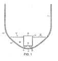
Figure 1 is a schematic section of the bottom of a reactor vessel according to the invention; -
Figure 2 is a top plan view of a lower gas distributor; -
Figure 3 is an amplified section through a part of the lower gas distributor; -
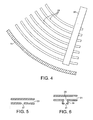
Figure 4 is a top plan view of part of the upper gas distributor; -
Figure 5 is a section through a simple nozzle; and -
Figure 6 is a section through an alternative form of nozzle. - Referring to
figure 1 , a slurry bubble column reactor comprises avessel 11, an upper gas distributor orsparger 12, a lower gas distributor orsparger 13 and atube 14. - The
vessel 11 is generally cylindrical and has a gas outlet at the top (not shown) and a liquid product outlet (not shown). At the bottom, thevessel 11 has acurved portion 15, a partconical section 16 and acurved base 17. Thetube 14 is a cylinder, open at thetop 18 andbottom 19. Theupper sparger 12 will be described in greater detail below with reference toFigure 4 but includes a series of concentric tubulargas distribution rings 21 which surround thetube 14 and are located at a level just below and close to theopen top 18 and just at the position where thecurved portion 15 of the vessel meets the part-conical section 16. Thelower sparger 13 will be described in greater detail below with reference tofigures 2 and 3 , but includes a series of concentric tubular gas distribution rings 22 which are located within the circumference of thetube 14 and at a level close to but beneath theopen bottom 19. - Turning now to
Figures 2 and 3 , thelower sparger 13 includes a maingas feed pipe 23, three equispacedradially extending manifolds 24 connected to thefeed pipe 23 and beneath themanifolds 24, therings 22. Therings 22 are connected to themanifolds 24 by means of respectivegas supply tubes 25. It will be appreciated that while threerings 22 are shown, there could be fewer or more, depending on various factors, such as the dimensions of the reactor and the rings themselves. - The
upper sparger 12 is shown inFigure 4 . It consists of a main gas feed ring outside the reactor (not shown), three radically extendingmanifolds 26 connected to the main gas feed ring through thevessel wall 11, and beneath themanifolds 26, therings 21. Therings 21 are connected to themanifolds 26 by means of respective gas supply tubes (not shown) in a similar fashion to thelower sparger 13. It will be appreciated that while sevenrings 21 are shown inFigure 4 , there could be fewer or more, depending on various factors, such as the dimensions of the reactor and therings 21 themselves. It will also be appreciated that a gas feed ring arrangement similar to that used for theupper sparger 12 could be used for thelower sparger 13, in place of the maingas feed pipe 23. - Each of the
rings ring Figures 5 and 6 . -
Figure 5 shows a nozzle in the form of asimple hole 27 in aring 21.Figure 6 shows an alternative nozzle in the form of ahole 28 in aring 21 covered by acowl 29 which has anaperture 31. In each case, thehole 27 or theaperture 31 faces downwards, 90° or less below the horizontal. The L/D-ratio for the nozzle should be >1, where L is the length of the nozzle and D is the diameter of the nozzle. Where the nozzle is a simple hole as inFigure 5 , the length L is the depth of the hole, i.e. the thickness of the ring wall. - In use, the reactant gas is conveyed to the upper and lower feed pipes and enters the
upper manifolds 26 and thelower manifolds 24. It then enters therespective rings reactor vessel 11 through the nozzles. In this way, each nozzle produces a downward gas jet into the slurry. The jets near the vessel bottom create motion of the slurry near the surface of thereactor vessel 11 to prevent the catalyst from settling and keep the catalyst in motion in that area. - The flushing effect of the
rings 21 of theupper sparger 12 which are further away from the vessel wall will tend to diminish. However this is addressed by thelower sparger 13. Gas from the nozzles in the lower sparger rings 22 rises into thetube 14. The density of the slurry in thetube 14 is therefore reduced. This tends to cause the slurry in thetube 14 to rise, which in turn draws slurry from thezone 32 down and into thetube 14. As this slurry descends, it flushes the wall of thevessel 11. This effect is assisted by the fact that in the region of thezone 32 the wall of thevessel 11 is the part-conical section 16. - There are several benefits to this design. Firstly, the two spargers can be designed without the need for a very narrow window for the distance between the reactor wall and the nozzles. There will be an improved turn down ratio of gas while still keeping the catalyst distributed in the liquid by using separate flow control to the 2 levels of sparger, the gas distribution can be controlled over a large feed flow range. Even with feeding gas only in the inner part of the reactor, a sufficient slurry circulation can be maintained to avoid sedimentation of catalyst outside the tube. The pressure drop can be kept low over the spargers due to operation at low gas velocity in sparger nozzles, but still maintain even distribution of gas, thus reducing attrition of the catalyst.
Table 1 below shows some examples for a reactor of 10 m ID. The slurry residence time below the top sparger outside tube should be as short as possible. Reactor shell diameter (m) 10 10 10 10 10 10 10 10 10 10 10 10 10 10 Total Number of rings 11 11 11 11 11 11 11 11 11 11 11 11 11 11 Diameter at upper sparger (m) 7 7 7 7 7 7 7 7 7 7 7 7 7 7 No. of rings in lower sparger 4 4 4 4 3 3 3 3 2 2 2 2 4 4 Tube diameter (m) 2.7 2.7 2.7 2.7 2.1 2.1 2.1 2.1 1.5 1.5 1.5 1.5 2.7 2.7 Tube height (m) 1.8 1.8 1.8 1.8 1.8 1.8 1.8 1.8 1.8 1.8 1.8 1.8 1.9 1.9 Gap between tube and reactor bottom (m) 0.1 0.2 0.3 0.4 0.1 0.2 0.3 0.4 0.1 0.2 0.3 0.4 0.3 0.3 Level diff. between lower and upper sparger (m) 1.8 1.8 1.8 1.8 1.8 1.8 1.8 1.8 1.8 1.8 1.8 1.8 1.9 1.9 Total coverage from sparger (% of reactor cross-sectional area) (%) 49 49 49 49 49 49 49 49 49 49 49 49 49 49 Lower sparger coverage (% of reactor cross-sectional area) (%) 7.3 7.3 7.3 7.3 4.4 4.4 4.4 4.4 2.3 2.3 2.3 2.3 7.3 7.3 Gas feed fraction in lower sparger (% of total gas feed) (%) 15 15 15 15 9 9 9 9 4.5 4.5 4.5 4.5 100 100 Liquid superficial velocity in tube (m/s) 0.5 0.8 1.1 1.2 0.6 1.0 1.2 1.3 0.8 1.2 1.3 1.4 0.7 0.5 Liquid Velocity in tube entrance (m/s) 3.4 2.8 2.4 2.0 3.2 2.6 2.1 1.7 3.0 2.2 1.7 1.3 1.5 1.1
Claims (17)
- A slurry bubble column reactor comprising a reactor vessel having a gas outlet and a liquid outlet, and a gas distributor arrangement in the region of the bottom of the vessel when in its orientation for use, the gas distributor arrangement comprising an upper gas distributor, a lower gas distributor spaced from the upper distributor to a position nearer the bottom of the vessel and a tube open at both ends and with its longitudinal axis extending generally vertically when the vessel is in its orientation for use, characterised in that the tube is arranged so that the upper gas distributor is located close to or in the vicinity of the upper open end of the tube, and the lower gas distributor is located at a level close to the lower end of the tube, whereby in use gas from the lower gas distributor rises into the tube, reduces the density of the slurry, and causes the slurry in the tube to rise.
- A reactor as claimed in Claim 1, characterised in that the upper gas distributor is located outside and at the level of or below the upper end of the tube and/or the lower gas distributor is radially within the circumference of the lower open end of the tube.
- A reactor as claimed in Claim 1 or Claim 2, characterised in that the upper gas distributor comprises one or more pipes, each having a plurality of upper nozzles.
- A reactor as claimed in any preceding claim, characterised in that the lower gas distributor comprises a manifold arrangement with a plurality of lower nozzles.
- A reactor as claimed in Claim 3 or Claim 4, characterised in that the upper or lower gas distributor comprises a plurality of generally circular or part-circular concentric pipes each having a plurality of upper or lower nozzles arranged along its length, where the concentric pipes may be tubular toroids or toroid sections, and where the upper or lower nozzles may all lie in a common generally horizontal plane.
- A reactor as claimed in any of claims 3 to 5, characterised in that the diameter of the openings of the upper or lower gas nozzles is equal to or greater than 5 mm, and in that the openings of the upper or lower nozzles may be arranged so that the principal axis of the jets of gas produced has an inclination of 90° or less below the horizontal.
- A reactor as claimed in any preceding claim, characterised in that the upper gas distributor is connected to an upper gas supply arrangement, and in that the lower gas distributor may be connected to a lower gas supply arrangement.
- A reactor as claimed in any of Claims 3 to 7, characterised in that the nozzles have an L/D ratio >1, where L is the length of the nozzle and D is the diameter of the nozzle.
- A reactor as claimed in any preceding claim, characterised in that the upper and lower gas distributors together represent from 30 to 100% of the cross-sectional area of the reactor, preferably from 40 to 80%, and where the lower gas distributor may represent from 2 to 12% of the cross-sectional area of the reactor, preferably from 5 to 8%.
- A reactor as claimed in any preceding claim, characterised in that when in use, the lower gas distributor is arranged to supply 4 to 20% of the gas flow to the reactor, preferably from 8 to 15%.
- A reactor as claimed in any preceding claim, characterised in that the tube is cylindrical and arranged generally in the reactor with its longitudinal axis substantially vertical.
- A reactor as claimed in any preceding claim, characterised in that the upper gas distributor is located at a position between 20% of the height of the tube above the top of the tube and half way up the tube, the upper gas distributor may be at a position less than 10% of the height of the tube beneath the top of the tube, and that the lower gas distributor may be located at a level between 3m above and 3m beneath the lower end of the tube.
- A reactor as claimed in any preceding claim, characterised in that beneath a main cylindrical portion of the vessel, the bottom of the vessel comprises a curved portion extending from the main cylindrical wall, a part-conical portion extending from the curved position, and a curved base, where the bottom of the tube may be at substantially the position where the part-conical portion joins the curved base.
- A method of conducting a chemical reaction involving gaseous reactants, characterised by supplying the gaseous reactants to a reactor as claimed in any of Claims 1 to 13 by way of the upper and lower gas distributors, in which method, the reactor contains a volume of slurry comprising a liquid phase and solid catalyst particles, and the catalyst particles are maintained in suspension in the slurry by rising gas bubbles from the gas distributors.
- A method as claimed in Claim 14, characterised in that the gas flowing through each individual nozzle exerts a dynamic pressure of less than 15 000 kg/m s2, and where a difference in density may be established between the slurry outside the tube and the slurry inside the tube by means of the gas from the lower distributor entering the tube, and this in turn may cause slurry outside the tube to flow downwards thereby sweeping the inside wall of the vessel, and then upwards through the tube as the gas from the lower distributor is entrained.
- A method as claimed in any of Claims 14 to 15, characterised in that the reaction is a Fischer-Tropsch synthesis, and in which the reaction temperature is in the range 150 to 300°C, and the reaction pressure is in the range 1 to 100 bar.
- A method as claimed in Claim 16, characterised in that the reaction temperature is in the range 200 to 260°C, and the reaction pressure is in the range 10 to 50 bar.
Priority Applications (1)
| Application Number | Priority Date | Filing Date | Title |
|---|---|---|---|
| PL09756343T PL2367616T3 (en) | 2008-11-18 | 2009-11-18 | Slurry bubble column reactor |
Applications Claiming Priority (2)
| Application Number | Priority Date | Filing Date | Title |
|---|---|---|---|
| GB0821094.0A GB2465554B (en) | 2008-11-18 | 2008-11-18 | Slurry bubble column reactor |
| PCT/GB2009/002698 WO2010058164A1 (en) | 2008-11-18 | 2009-11-18 | Slurry bubble column reactor |
Publications (2)
| Publication Number | Publication Date |
|---|---|
| EP2367616A1 EP2367616A1 (en) | 2011-09-28 |
| EP2367616B1 true EP2367616B1 (en) | 2013-05-15 |
Family
ID=40194840
Family Applications (1)
| Application Number | Title | Priority Date | Filing Date |
|---|---|---|---|
| EP09756343.1A Not-in-force EP2367616B1 (en) | 2008-11-18 | 2009-11-18 | Slurry bubble column reactor |
Country Status (7)
| Country | Link |
|---|---|
| US (1) | US9039980B2 (en) |
| EP (1) | EP2367616B1 (en) |
| KR (1) | KR101654804B1 (en) |
| AU (1) | AU2009317051A1 (en) |
| GB (1) | GB2465554B (en) |
| PL (1) | PL2367616T3 (en) |
| WO (1) | WO2010058164A1 (en) |
Families Citing this family (13)
| Publication number | Priority date | Publication date | Assignee | Title |
|---|---|---|---|---|
| GB2444055B (en) * | 2006-11-23 | 2011-11-23 | Gtl F1 Ag | Gas to liquids plant with consecutive Fischer-Tropsch reactors and hydrogen make-up |
| GB2466315B (en) | 2008-12-22 | 2013-01-09 | Gtl F1 Ag | Apparatus and method for conducting a Fischer-Tropsch synthesis reaction |
| GB2471338B (en) | 2009-06-26 | 2014-12-24 | Gtl F1 Ag | Apparatus and process for three-phase reacton |
| DE102009052670B4 (en) * | 2009-11-12 | 2017-10-05 | Sartorius Stedim Biotech Gmbh | Fumigation device for bioreactors |
| NL2010005C2 (en) * | 2012-12-18 | 2014-06-23 | Pwn Technologies B V | Reactor vessel for suspending media particles in a fluid. |
| JP2014136767A (en) * | 2013-01-17 | 2014-07-28 | Japan Oil Gas & Metals National Corp | Reaction apparatus for synthesizing hydrocarbon |
| JP6145348B2 (en) * | 2013-07-30 | 2017-06-07 | 新日鉄住金エンジニアリング株式会社 | Reactor for hydrocarbon synthesis |
| CN104722233A (en) * | 2013-08-23 | 2015-06-24 | 薛应东 | Stirrer |
| WO2017029581A1 (en) * | 2015-08-19 | 2017-02-23 | Sasol Technology Proprietary Limited | A method of operating a slurry bubble column reactor |
| ES3038909T3 (en) | 2016-02-29 | 2025-10-15 | Uop Llc | Method and apparatus for fluidizing spent catalyst |
| CA3167977A1 (en) * | 2020-02-12 | 2021-08-19 | Kanuparthy Naga RAJA | Gas distributor for bubble column reactor |
| KR102728114B1 (en) | 2020-09-22 | 2024-11-07 | 주식회사 엘지화학 | Apparatus for preparing oligomer |
| CN114225844B (en) * | 2021-11-11 | 2022-10-14 | 华南理工大学 | Multistage slurry bed reactor and working method thereof |
Family Cites Families (40)
| Publication number | Priority date | Publication date | Assignee | Title |
|---|---|---|---|---|
| GB1250222A (en) * | 1968-10-25 | 1971-10-20 | ||
| GB1265770A (en) * | 1969-07-01 | 1972-03-08 | ||
| JPS5254078A (en) * | 1975-10-30 | 1977-05-02 | Mitsubishi Gas Chem Co Inc | Method of incuvating microorganisms and appratus for the same |
| US4166840A (en) * | 1975-12-24 | 1979-09-04 | Fisons Limited | Process for producing ammonium phosphate from ammonia and wet process phosphoric acid |
| US4595145A (en) * | 1984-10-01 | 1986-06-17 | Texaco Inc. | Air distribution apparatus for a fluid catalytic cracking catalyst regenerator |
| US4610851A (en) * | 1984-11-28 | 1986-09-09 | Colvert James H | Air distributor for FCCU catalyst regenerator |
| US4624968A (en) | 1985-12-30 | 1986-11-25 | Exxon Research And Engineering Company | Multi-stage Fischer-Tropsch process |
| US5166072A (en) * | 1986-06-26 | 1992-11-24 | Bayer Aktiengesellschaft | Apparatus for the cultivation of immobilized micro-organisms |
| CA2105940C (en) | 1992-10-05 | 2001-12-25 | Robert M. Koros | Bubble column, tube side slurry process and apparatus |
| NZ250750A (en) | 1993-01-27 | 1995-02-24 | Sasol Chem Ind Pty | Reacting gases in a slurry bed which contains a filtration zone to separate liquid product |
| US5527473A (en) | 1993-07-15 | 1996-06-18 | Ackerman; Carl D. | Process for performing reactions in a liquid-solid catalyst slurry |
| US5827903A (en) | 1996-01-31 | 1998-10-27 | The United States Of America As Represented By The Department Of Energy | Separation of catalyst from Fischer-Tropsch slurry |
| ZA98586B (en) * | 1997-02-20 | 1999-07-23 | Sasol Tech Pty Ltd | "Hydrogenation of hydrocarbons". |
| US6160026A (en) | 1997-09-24 | 2000-12-12 | Texaco Inc. | Process for optimizing hydrocarbon synthesis |
| US6156809A (en) | 1999-04-21 | 2000-12-05 | Reema International Corp. | Multiple reactor system and method for fischer-tropsch synthesis |
| GB0013793D0 (en) | 2000-06-06 | 2000-07-26 | Bp Amoco Plc | Process |
| JP2004511619A (en) | 2000-10-13 | 2004-04-15 | ビーピー エクスプロレーション オペレーティング カンパニー リミテッド | Fischer-Tropsch synthesis |
| US20030050348A1 (en) | 2001-03-26 | 2003-03-13 | Kennedy Paul Edwin | Hydrocarbon conversion process using a plurality of synthesis gas sources |
| WO2002096833A2 (en) | 2001-05-25 | 2002-12-05 | Bp Exploration Operating Company Limited | Fischer-tropsch process |
| US7060228B2 (en) | 2001-07-06 | 2006-06-13 | Institut Francais Du Petrole | Internal device for separating a mixture that comprises at least one gaseous phase and one liquid phase |
| US7115669B2 (en) | 2001-07-25 | 2006-10-03 | Conocophillips Company | Minimizing the volume or maximizing the production rate of slurry bubble reactors by using large gas flow rates and moderate single pass conversion |
| FR2832937B1 (en) | 2001-12-04 | 2004-01-16 | Technip France | METHOD AND DEVICE FOR CHEMICAL REACTION BETWEEN A GAS AND AT LEAST ONE COMPOUND IN SOLUTION, IMPLEMENTED IN THE PRESENCE OF A SOLID CATALYST |
| AU2003260828A1 (en) | 2002-09-19 | 2004-04-08 | Sasol Technology (Proprietary) Limited | Hydrocarbon synthesis |
| ITMI20030969A1 (en) | 2003-05-15 | 2004-11-16 | Enitecnologie Spa | PROCEDURE FOR THE CONTINUOUS PRODUCTION OF HYDROCARBONS FROM SYNTHESIS GAS IN SUSPENSION REACTORS AND FOR THE SEPARATION OF THE LIQUID PHASE PRODUCED FROM THE SOLID PHASE. |
| CA2532513A1 (en) | 2003-07-15 | 2005-01-20 | Sasol Technology (Proprietary) Limited | Process for separating a catalyst from a liquid |
| US6992114B2 (en) | 2003-11-25 | 2006-01-31 | Chevron U.S.A. Inc. | Control of CO2 emissions from a Fischer-Tropsch facility by use of multiple reactors |
| JP2007527793A (en) * | 2004-03-08 | 2007-10-04 | シエル・インターナシヨネイル・リサーチ・マーチヤツピイ・ベー・ウイ | Gas distributor for reactor |
| GB2412612B (en) * | 2004-04-02 | 2008-10-29 | Statoil Asa | Slurry bubble column reactor |
| US7375143B2 (en) | 2004-11-22 | 2008-05-20 | Conocophillips Company | Catalyst recover from a slurry |
| ITMI20060492A1 (en) * | 2005-03-17 | 2006-09-18 | Sasol Tech Pty Ltd | PROCEDURE FOR THE OPERATION OF A THREE-STAGE REACTOR FOR SUSPENSIONS AND THREE-STAGE REACTORS |
| RU2409608C2 (en) | 2005-07-20 | 2011-01-20 | Шелл Интернэшнл Рисерч Маатсхаппий Б.В. | Multi-step fischer-tropsch method |
| ATE442898T1 (en) | 2005-10-04 | 2009-10-15 | Pet Oil & Gas Corp S Africa | FILTRATION PROCESS |
| AU2006323998B2 (en) | 2005-12-09 | 2009-10-29 | Shell Internationale Research Maatschappij B.V. | Method to start a process for producing hydrocarbons from synthesis gas |
| JP4874660B2 (en) | 2006-01-30 | 2012-02-15 | 新日鉄エンジニアリング株式会社 | Bubble column type hydrocarbon synthesis reactor |
| GB2444055B (en) | 2006-11-23 | 2011-11-23 | Gtl F1 Ag | Gas to liquids plant with consecutive Fischer-Tropsch reactors and hydrogen make-up |
| WO2008146239A2 (en) | 2007-05-28 | 2008-12-04 | The Petroleum Oil And Gas Corporation Of South Africa (Pty) Ltd | Removal of fine particles from a fischer tropsch stream |
| US7905937B2 (en) | 2007-09-13 | 2011-03-15 | Koch-Glitch, LP | Two-stage mist eliminator and method |
| CN101396647B (en) | 2007-09-29 | 2011-03-16 | 中科合成油技术有限公司 | Gas-liquid-solid three-phase suspended bed reactor for f-t synthesis and use thereof |
| GB2466315B (en) | 2008-12-22 | 2013-01-09 | Gtl F1 Ag | Apparatus and method for conducting a Fischer-Tropsch synthesis reaction |
| GB2471338B (en) | 2009-06-26 | 2014-12-24 | Gtl F1 Ag | Apparatus and process for three-phase reacton |
-
2008
- 2008-11-18 GB GB0821094.0A patent/GB2465554B/en active Active
-
2009
- 2009-11-10 US US13/130,041 patent/US9039980B2/en not_active Expired - Fee Related
- 2009-11-10 AU AU2009317051A patent/AU2009317051A1/en not_active Abandoned
- 2009-11-18 PL PL09756343T patent/PL2367616T3/en unknown
- 2009-11-18 WO PCT/GB2009/002698 patent/WO2010058164A1/en not_active Ceased
- 2009-11-18 KR KR1020117014095A patent/KR101654804B1/en not_active Expired - Fee Related
- 2009-11-18 EP EP09756343.1A patent/EP2367616B1/en not_active Not-in-force
Also Published As
| Publication number | Publication date |
|---|---|
| EP2367616A1 (en) | 2011-09-28 |
| GB2465554B (en) | 2013-03-13 |
| GB0821094D0 (en) | 2008-12-24 |
| WO2010058164A8 (en) | 2015-07-02 |
| WO2010058164A1 (en) | 2010-05-27 |
| US20110313062A1 (en) | 2011-12-22 |
| GB2465554A (en) | 2010-05-26 |
| US9039980B2 (en) | 2015-05-26 |
| KR20110106856A (en) | 2011-09-29 |
| AU2009317051A1 (en) | 2010-05-27 |
| PL2367616T3 (en) | 2013-12-31 |
| KR101654804B1 (en) | 2016-09-06 |
| JP5734871B2 (en) | 2015-06-17 |
| JP2012509175A (en) | 2012-04-19 |
Similar Documents
| Publication | Publication Date | Title |
|---|---|---|
| US9039980B2 (en) | Slurry bubble column reactor | |
| EP2055674B1 (en) | Apparatus for producing trichlorosilane and method for producing thrichlorosilane | |
| JP5359082B2 (en) | Trichlorosilane production apparatus and trichlorosilane production method | |
| EP1735086B1 (en) | Method of conducting a chemical reaction in a slurry bubble column reactor | |
| EP1720647B1 (en) | Reactor with a gas distributor | |
| EP2542335B1 (en) | Gas-liquid flow distribution device for downflow catalytic reactors | |
| EP2718406B1 (en) | Grid plate assembly for a hydroconversion reactor and use thereof | |
| CN103354764B (en) | Slurry Phase Equipment | |
| EP3218092B1 (en) | Reaction device with air-lift type internal circulation | |
| US5723041A (en) | Process and apparatus for promoting annularly uniform flow | |
| US11000820B2 (en) | Device for distributing a polyphase mixture in a chamber containing a fluidized medium | |
| JP4603784B2 (en) | Jet mixing of process fluids in a fixed bed reactor. | |
| CN104302737B (en) | Raw material in mixed flow fluidized catalytic cracking unit and the mixing device of catalyzer | |
| KR20230125235A (en) | Hydroformylation Reaction Process | |
| JP5734871B6 (en) | Slurry foam column reactor | |
| SU1708829A1 (en) | Gas-lift bubbling apparatus | |
| JP2007269655A (en) | Reaction method and reaction apparatus | |
| US20160361692A1 (en) | Process and device for dispersing gas in a liquid | |
| JP3197871U (en) | Hydrodynamic reactor | |
| WO2006070005A1 (en) | Reactor for solid/liquid/gas reactions | |
| JPH0127772B2 (en) | ||
| PL192577B1 (en) | Production plant for obtaining cyclohexanol and cyclohexanone by oxidation of cyclohexane |
Legal Events
| Date | Code | Title | Description |
|---|---|---|---|
| PUAI | Public reference made under article 153(3) epc to a published international application that has entered the european phase |
Free format text: ORIGINAL CODE: 0009012 |
|
| 17P | Request for examination filed |
Effective date: 20110620 |
|
| AK | Designated contracting states |
Kind code of ref document: A1 Designated state(s): AT BE BG CH CY CZ DE DK EE ES FI FR GB GR HR HU IE IS IT LI LT LU LV MC MK MT NL NO PL PT RO SE SI SK SM TR |
|
| DAX | Request for extension of the european patent (deleted) | ||
| GRAP | Despatch of communication of intention to grant a patent |
Free format text: ORIGINAL CODE: EPIDOSNIGR1 |
|
| GRAS | Grant fee paid |
Free format text: ORIGINAL CODE: EPIDOSNIGR3 |
|
| GRAA | (expected) grant |
Free format text: ORIGINAL CODE: 0009210 |
|
| AK | Designated contracting states |
Kind code of ref document: B1 Designated state(s): AT BE BG CH CY CZ DE DK EE ES FI FR GB GR HR HU IE IS IT LI LT LU LV MC MK MT NL NO PL PT RO SE SI SK SM TR |
|
| REG | Reference to a national code |
Ref country code: GB Ref legal event code: FG4D Ref country code: CH Ref legal event code: EP |
|
| REG | Reference to a national code |
Ref country code: AT Ref legal event code: REF Ref document number: 611846 Country of ref document: AT Kind code of ref document: T Effective date: 20130615 |
|
| REG | Reference to a national code |
Ref country code: IE Ref legal event code: FG4D |
|
| REG | Reference to a national code |
Ref country code: DE Ref legal event code: R096 Ref document number: 602009015742 Country of ref document: DE Effective date: 20130711 |
|
| REG | Reference to a national code |
Ref country code: NO Ref legal event code: T2 Effective date: 20130515 |
|
| RAP2 | Party data changed (patent owner data changed or rights of a patent transferred) |
Owner name: GTL.F1 AG |
|
| REG | Reference to a national code |
Ref country code: AT Ref legal event code: MK05 Ref document number: 611846 Country of ref document: AT Kind code of ref document: T Effective date: 20130515 |
|
| REG | Reference to a national code |
Ref country code: LT Ref legal event code: MG4D |
|
| REG | Reference to a national code |
Ref country code: NL Ref legal event code: VDEP Effective date: 20130515 |
|
| PG25 | Lapsed in a contracting state [announced via postgrant information from national office to epo] |
Ref country code: AT Free format text: LAPSE BECAUSE OF FAILURE TO SUBMIT A TRANSLATION OF THE DESCRIPTION OR TO PAY THE FEE WITHIN THE PRESCRIBED TIME-LIMIT Effective date: 20130515 Ref country code: PT Free format text: LAPSE BECAUSE OF FAILURE TO SUBMIT A TRANSLATION OF THE DESCRIPTION OR TO PAY THE FEE WITHIN THE PRESCRIBED TIME-LIMIT Effective date: 20130916 Ref country code: GR Free format text: LAPSE BECAUSE OF FAILURE TO SUBMIT A TRANSLATION OF THE DESCRIPTION OR TO PAY THE FEE WITHIN THE PRESCRIBED TIME-LIMIT Effective date: 20130816 Ref country code: ES Free format text: LAPSE BECAUSE OF FAILURE TO SUBMIT A TRANSLATION OF THE DESCRIPTION OR TO PAY THE FEE WITHIN THE PRESCRIBED TIME-LIMIT Effective date: 20130826 Ref country code: LT Free format text: LAPSE BECAUSE OF FAILURE TO SUBMIT A TRANSLATION OF THE DESCRIPTION OR TO PAY THE FEE WITHIN THE PRESCRIBED TIME-LIMIT Effective date: 20130515 Ref country code: SI Free format text: LAPSE BECAUSE OF FAILURE TO SUBMIT A TRANSLATION OF THE DESCRIPTION OR TO PAY THE FEE WITHIN THE PRESCRIBED TIME-LIMIT Effective date: 20130515 Ref country code: IS Free format text: LAPSE BECAUSE OF FAILURE TO SUBMIT A TRANSLATION OF THE DESCRIPTION OR TO PAY THE FEE WITHIN THE PRESCRIBED TIME-LIMIT Effective date: 20130915 Ref country code: SE Free format text: LAPSE BECAUSE OF FAILURE TO SUBMIT A TRANSLATION OF THE DESCRIPTION OR TO PAY THE FEE WITHIN THE PRESCRIBED TIME-LIMIT Effective date: 20130515 |
|
| PG25 | Lapsed in a contracting state [announced via postgrant information from national office to epo] |
Ref country code: BG Free format text: LAPSE BECAUSE OF FAILURE TO SUBMIT A TRANSLATION OF THE DESCRIPTION OR TO PAY THE FEE WITHIN THE PRESCRIBED TIME-LIMIT Effective date: 20130815 Ref country code: HR Free format text: LAPSE BECAUSE OF FAILURE TO SUBMIT A TRANSLATION OF THE DESCRIPTION OR TO PAY THE FEE WITHIN THE PRESCRIBED TIME-LIMIT Effective date: 20130515 |
|
| PG25 | Lapsed in a contracting state [announced via postgrant information from national office to epo] |
Ref country code: LV Free format text: LAPSE BECAUSE OF FAILURE TO SUBMIT A TRANSLATION OF THE DESCRIPTION OR TO PAY THE FEE WITHIN THE PRESCRIBED TIME-LIMIT Effective date: 20130515 |
|
| REG | Reference to a national code |
Ref country code: PL Ref legal event code: T3 |
|
| PG25 | Lapsed in a contracting state [announced via postgrant information from national office to epo] |
Ref country code: EE Free format text: LAPSE BECAUSE OF FAILURE TO SUBMIT A TRANSLATION OF THE DESCRIPTION OR TO PAY THE FEE WITHIN THE PRESCRIBED TIME-LIMIT Effective date: 20130515 Ref country code: DK Free format text: LAPSE BECAUSE OF FAILURE TO SUBMIT A TRANSLATION OF THE DESCRIPTION OR TO PAY THE FEE WITHIN THE PRESCRIBED TIME-LIMIT Effective date: 20130515 Ref country code: BE Free format text: LAPSE BECAUSE OF FAILURE TO SUBMIT A TRANSLATION OF THE DESCRIPTION OR TO PAY THE FEE WITHIN THE PRESCRIBED TIME-LIMIT Effective date: 20130515 Ref country code: SK Free format text: LAPSE BECAUSE OF FAILURE TO SUBMIT A TRANSLATION OF THE DESCRIPTION OR TO PAY THE FEE WITHIN THE PRESCRIBED TIME-LIMIT Effective date: 20130515 Ref country code: CZ Free format text: LAPSE BECAUSE OF FAILURE TO SUBMIT A TRANSLATION OF THE DESCRIPTION OR TO PAY THE FEE WITHIN THE PRESCRIBED TIME-LIMIT Effective date: 20130515 |
|
| PGFP | Annual fee paid to national office [announced via postgrant information from national office to epo] |
Ref country code: NO Payment date: 20131120 Year of fee payment: 5 |
|
| PG25 | Lapsed in a contracting state [announced via postgrant information from national office to epo] |
Ref country code: NL Free format text: LAPSE BECAUSE OF FAILURE TO SUBMIT A TRANSLATION OF THE DESCRIPTION OR TO PAY THE FEE WITHIN THE PRESCRIBED TIME-LIMIT Effective date: 20130515 Ref country code: IT Free format text: LAPSE BECAUSE OF FAILURE TO SUBMIT A TRANSLATION OF THE DESCRIPTION OR TO PAY THE FEE WITHIN THE PRESCRIBED TIME-LIMIT Effective date: 20130515 Ref country code: RO Free format text: LAPSE BECAUSE OF FAILURE TO SUBMIT A TRANSLATION OF THE DESCRIPTION OR TO PAY THE FEE WITHIN THE PRESCRIBED TIME-LIMIT Effective date: 20130515 |
|
| PGFP | Annual fee paid to national office [announced via postgrant information from national office to epo] |
Ref country code: FI Payment date: 20131118 Year of fee payment: 5 |
|
| PLBE | No opposition filed within time limit |
Free format text: ORIGINAL CODE: 0009261 |
|
| STAA | Information on the status of an ep patent application or granted ep patent |
Free format text: STATUS: NO OPPOSITION FILED WITHIN TIME LIMIT |
|
| 26N | No opposition filed |
Effective date: 20140218 |
|
| REG | Reference to a national code |
Ref country code: DE Ref legal event code: R097 Ref document number: 602009015742 Country of ref document: DE Effective date: 20140218 |
|
| REG | Reference to a national code |
Ref country code: CH Ref legal event code: PL |
|
| PG25 | Lapsed in a contracting state [announced via postgrant information from national office to epo] |
Ref country code: LI Free format text: LAPSE BECAUSE OF NON-PAYMENT OF DUE FEES Effective date: 20131130 Ref country code: MC Free format text: LAPSE BECAUSE OF FAILURE TO SUBMIT A TRANSLATION OF THE DESCRIPTION OR TO PAY THE FEE WITHIN THE PRESCRIBED TIME-LIMIT Effective date: 20130515 Ref country code: CH Free format text: LAPSE BECAUSE OF NON-PAYMENT OF DUE FEES Effective date: 20131130 |
|
| REG | Reference to a national code |
Ref country code: IE Ref legal event code: MM4A |
|
| PG25 | Lapsed in a contracting state [announced via postgrant information from national office to epo] |
Ref country code: IE Free format text: LAPSE BECAUSE OF NON-PAYMENT OF DUE FEES Effective date: 20131118 |
|
| PG25 | Lapsed in a contracting state [announced via postgrant information from national office to epo] |
Ref country code: SM Free format text: LAPSE BECAUSE OF FAILURE TO SUBMIT A TRANSLATION OF THE DESCRIPTION OR TO PAY THE FEE WITHIN THE PRESCRIBED TIME-LIMIT Effective date: 20130515 |
|
| PG25 | Lapsed in a contracting state [announced via postgrant information from national office to epo] |
Ref country code: TR Free format text: LAPSE BECAUSE OF FAILURE TO SUBMIT A TRANSLATION OF THE DESCRIPTION OR TO PAY THE FEE WITHIN THE PRESCRIBED TIME-LIMIT Effective date: 20130515 Ref country code: CY Free format text: LAPSE BECAUSE OF FAILURE TO SUBMIT A TRANSLATION OF THE DESCRIPTION OR TO PAY THE FEE WITHIN THE PRESCRIBED TIME-LIMIT Effective date: 20130515 |
|
| PG25 | Lapsed in a contracting state [announced via postgrant information from national office to epo] |
Ref country code: FI Free format text: LAPSE BECAUSE OF NON-PAYMENT OF DUE FEES Effective date: 20141118 Ref country code: MK Free format text: LAPSE BECAUSE OF FAILURE TO SUBMIT A TRANSLATION OF THE DESCRIPTION OR TO PAY THE FEE WITHIN THE PRESCRIBED TIME-LIMIT Effective date: 20130515 Ref country code: NO Free format text: LAPSE BECAUSE OF NON-PAYMENT OF DUE FEES Effective date: 20141130 Ref country code: HU Free format text: LAPSE BECAUSE OF FAILURE TO SUBMIT A TRANSLATION OF THE DESCRIPTION OR TO PAY THE FEE WITHIN THE PRESCRIBED TIME-LIMIT; INVALID AB INITIO Effective date: 20091118 Ref country code: LU Free format text: LAPSE BECAUSE OF NON-PAYMENT OF DUE FEES Effective date: 20131118 |
|
| PG25 | Lapsed in a contracting state [announced via postgrant information from national office to epo] |
Ref country code: MT Free format text: LAPSE BECAUSE OF FAILURE TO SUBMIT A TRANSLATION OF THE DESCRIPTION OR TO PAY THE FEE WITHIN THE PRESCRIBED TIME-LIMIT Effective date: 20130515 |
|
| REG | Reference to a national code |
Ref country code: FR Ref legal event code: PLFP Year of fee payment: 7 |
|
| PGFP | Annual fee paid to national office [announced via postgrant information from national office to epo] |
Ref country code: GB Payment date: 20151103 Year of fee payment: 7 |
|
| REG | Reference to a national code |
Ref country code: FR Ref legal event code: PLFP Year of fee payment: 8 |
|
| GBPC | Gb: european patent ceased through non-payment of renewal fee |
Effective date: 20161118 |
|
| REG | Reference to a national code |
Ref country code: FR Ref legal event code: PLFP Year of fee payment: 9 |
|
| PG25 | Lapsed in a contracting state [announced via postgrant information from national office to epo] |
Ref country code: GB Free format text: LAPSE BECAUSE OF NON-PAYMENT OF DUE FEES Effective date: 20161118 |
|
| PGFP | Annual fee paid to national office [announced via postgrant information from national office to epo] |
Ref country code: DE Payment date: 20191107 Year of fee payment: 11 |
|
| PGFP | Annual fee paid to national office [announced via postgrant information from national office to epo] |
Ref country code: PL Payment date: 20191108 Year of fee payment: 11 Ref country code: FR Payment date: 20191108 Year of fee payment: 11 |
|
| REG | Reference to a national code |
Ref country code: DE Ref legal event code: R119 Ref document number: 602009015742 Country of ref document: DE |
|
| PG25 | Lapsed in a contracting state [announced via postgrant information from national office to epo] |
Ref country code: FR Free format text: LAPSE BECAUSE OF NON-PAYMENT OF DUE FEES Effective date: 20201130 |
|
| PG25 | Lapsed in a contracting state [announced via postgrant information from national office to epo] |
Ref country code: DE Free format text: LAPSE BECAUSE OF NON-PAYMENT OF DUE FEES Effective date: 20210601 |
|
| PG25 | Lapsed in a contracting state [announced via postgrant information from national office to epo] |
Ref country code: PL Free format text: LAPSE BECAUSE OF NON-PAYMENT OF DUE FEES Effective date: 20201118 |