EP2367412A1 - Thermal-fluid-simulating analyzing apparatus, method and program - Google Patents
Thermal-fluid-simulating analyzing apparatus, method and program Download PDFInfo
- Publication number
- EP2367412A1 EP2367412A1 EP20100174364 EP10174364A EP2367412A1 EP 2367412 A1 EP2367412 A1 EP 2367412A1 EP 20100174364 EP20100174364 EP 20100174364 EP 10174364 A EP10174364 A EP 10174364A EP 2367412 A1 EP2367412 A1 EP 2367412A1
- Authority
- EP
- European Patent Office
- Prior art keywords
- analysis
- condition
- simulation
- thermal
- thermal fluid
- Prior art date
- Legal status (The legal status is an assumption and is not a legal conclusion. Google has not performed a legal analysis and makes no representation as to the accuracy of the status listed.)
- Withdrawn
Links
Images




Classifications
-
- G—PHYSICS
- G06—COMPUTING OR CALCULATING; COUNTING
- G06F—ELECTRIC DIGITAL DATA PROCESSING
- G06F30/00—Computer-aided design [CAD]
- G06F30/20—Design optimisation, verification or simulation
- G06F30/28—Design optimisation, verification or simulation using fluid dynamics, e.g. using Navier-Stokes equations or computational fluid dynamics [CFD]
-
- G—PHYSICS
- G06—COMPUTING OR CALCULATING; COUNTING
- G06F—ELECTRIC DIGITAL DATA PROCESSING
- G06F30/00—Computer-aided design [CAD]
-
- G—PHYSICS
- G06—COMPUTING OR CALCULATING; COUNTING
- G06F—ELECTRIC DIGITAL DATA PROCESSING
- G06F30/00—Computer-aided design [CAD]
- G06F30/10—Geometric CAD
- G06F30/13—Architectural design, e.g. computer-aided architectural design [CAAD] related to design of buildings, bridges, landscapes, production plants or roads
-
- G—PHYSICS
- G06—COMPUTING OR CALCULATING; COUNTING
- G06F—ELECTRIC DIGITAL DATA PROCESSING
- G06F30/00—Computer-aided design [CAD]
- G06F30/20—Design optimisation, verification or simulation
- G06F30/23—Design optimisation, verification or simulation using finite element methods [FEM] or finite difference methods [FDM]
-
- G—PHYSICS
- G06—COMPUTING OR CALCULATING; COUNTING
- G06F—ELECTRIC DIGITAL DATA PROCESSING
- G06F2111/00—Details relating to CAD techniques
- G06F2111/10—Numerical modelling
-
- G—PHYSICS
- G06—COMPUTING OR CALCULATING; COUNTING
- G06F—ELECTRIC DIGITAL DATA PROCESSING
- G06F2119/00—Details relating to the type or aim of the analysis or the optimisation
- G06F2119/08—Thermal analysis or thermal optimisation
-
- H—ELECTRICITY
- H05—ELECTRIC TECHNIQUES NOT OTHERWISE PROVIDED FOR
- H05K—PRINTED CIRCUITS; CASINGS OR CONSTRUCTIONAL DETAILS OF ELECTRIC APPARATUS; MANUFACTURE OF ASSEMBLAGES OF ELECTRICAL COMPONENTS
- H05K7/00—Constructional details common to different types of electric apparatus
- H05K7/20—Modifications to facilitate cooling, ventilating, or heating
- H05K7/20536—Modifications to facilitate cooling, ventilating, or heating for racks or cabinets of standardised dimensions, e.g. electronic racks for aircraft or telecommunication equipment
- H05K7/20609—Air circulating in closed loop within cabinets wherein heat is removed through air-to-liquid heat-exchanger
-
- H—ELECTRICITY
- H05—ELECTRIC TECHNIQUES NOT OTHERWISE PROVIDED FOR
- H05K—PRINTED CIRCUITS; CASINGS OR CONSTRUCTIONAL DETAILS OF ELECTRIC APPARATUS; MANUFACTURE OF ASSEMBLAGES OF ELECTRICAL COMPONENTS
- H05K7/00—Constructional details common to different types of electric apparatus
- H05K7/20—Modifications to facilitate cooling, ventilating, or heating
- H05K7/20709—Modifications to facilitate cooling, ventilating, or heating for server racks or cabinets; for data centers, e.g. 19-inch computer racks
- H05K7/20836—Thermal management, e.g. server temperature control
Definitions
- the embodiments discussed herein are directed to thermal-fluid-simulation analyzing apparatuses.
- IT information technology
- the temperature in the data centers tend to become high because the IT devices are closely arranged in rack devices and the consumed power of the data centers have increased. As a result, sometimes the IT devices are not cooled down sufficiently, which causes problems.
- the temperature distribution in data centers is examined, it is known that the IT devices and the rack devices are arranged at different locations in different installation environments, and that the amount of heat generated by the central processing units (CPUs) in the IT devices varies, and the amount of heat generated by the rack devices varies. Therefore, some IT devices are not cooled down, and heated beyond a permissible temperature. Furthermore, such an increase in the temperature in a data center may cause a malfunction of the air conditioners that supply the cooling air; for example, abnormal operation or abnormal stop of the air conditioner may occur.
- a sensor or the like is employed (see, for example, Japanese Laid-open Patent Publication No. 2008-034715 , and Japanese Laid-open Patent Publication No. 08-095672 ).
- This prediction technique using a sensor or the like takes a long time to rectify the problems. This is because this prediction technique using a sensor predicts an abnormal phenomenon, which would cause a problem, based on measurements at limited measurement points, and identifies and analyzes factors causing the abnormal condition and then formulate a countermeasure for the problem making full use of various types of thermal technologies and analysis technologies.
- a technique utilizing thermal-fluid simulation is employed for predicting an abnormal phenomenon other than the above-described prediction technique utilizing the sensor.
- various actions are taken: for example, the measurement data such as temperature data is analyzed for identifying the problem; the situation is assessed based on a simulation; and a countermeasure is taken.
- a simulator which conducts a thermal fluid simulation, performs a series of processes to assess the situation based on a thermal-fluid simulation: for example, the simulator performs a series of processes for collecting an analysis conditions, formulating an analysis model, generating a mesh, executing calculations, and analyzing a result.
- the simulator first collects analysis conditions that include floor information, information about the arrangement of rack devices, grilles, and air conditioners, amounts of rack-generated heat, volumes of rack exhaust-air, grille aperture ratios, cooling performances of the air conditioners, and flow volumes of the air conditioners.
- the simulator obtains the analysis conditions from, for example, a database which is created by an administrator and which contains information about arrangement of devices inside the data center.
- the simulator then performs model shaping, heat-generating-condition setting, and air-flow setting, to generate an analysis model.
- the simulator divides the analysis model into meshes by transforming conservation equations (e.g., the Navier-Stokes equation) of the air flow and the thermal transfer in the data center into finite volumes. If the space to be analyzed is large or if a highly accurate simulation is needed, the number of meshes is increased and the number of calculations is increased.
- conservation equations e.g., the Navier-Stokes equation
- the simulator performs coupling so that one parameter of the conservation equation, e.g., the Navier-Stokes equation, depends on another parameter or a nearby value and then performs a finite iterative calculation repeatedly until the error of the conservation equation decreases to an allowable level, thereby causing the solutions to converge and thus solving the conservation equation. More specifically, the simulator causes the solutions of the Navier-Stokes equation to converge using a widely-known splitting method, for example, Semi-Implicit Method for Pressure Linked Equations (SIMPLE) algorism.
- a widely-known splitting method for example, Semi-Implicit Method for Pressure Linked Equations (SIMPLE) algorism.
- the simulator calculates, using the conservation equation, both the flow velocity in the x axis of the mesh-divided space and the flow velocity in the y axis.
- the simulator calculates the pressure in the mesh-divided space, updates the flow velocity and the density for the conservation equation, and calculates the temperature, for example, using another equation, e.g., the heat equation.
- the simulator determines whether an error between a threshold and a boundary value that is determined according to the calculated flow velocities and the calculated temperature is within an allowable range, i.e., whether a converged solution is obtained for the boundary value. If a converged solution is obtained for the boundary value, the simulator ends the simulation. If a converged solution is not obtained for the boundary value, the simulator repeats the above simulation until a converged solution is obtained for the boundary value. After the simulation ends, the administrator, etc., assesses the current situation using the simulation result.
- the conventional simulator when a temperature problem occurs in the data center, the conventional simulator initializes previously calculated results after collecting the analysis conditions and generating the analysis model as describe earlier. Thereafter, the conventional simulator performs a calculation about 200 times to create the information for analyzing the situation. Therefore, it takes a long time for the administrator, etc., to analyze the situation and, even longer time to take countermeasures for the problem.
- thermal-fluid-simulation analyzing apparatus that decreases the time taken for a thermal fluid simulation that is performed to analyze the air-conditioning state and thus enables a quick analysis of the situation.
- a thermal-fluid-simulation analyzing apparatus includes: an execution unit that generates an analysis model using analysis conditions and that conducts a first thermal fluid simulation analysis based on the generated analysis model, the analysis condition being a condition in a thermal fluid simulation analysis according to which an air conditioning state in a predetermined space is simulated; an analysis-condition collecting unit that, when a predetermined period passes after the first thermal fluid simulation analysis by the execution unit, collects analysis conditions; a condition extracting unit that extracts a boundary condition from the analysis conditions that are collected by the analysis-condition collecting unit when the predetermined period passes after the first thermal fluid simulation analysis, the boundary condition being an analysis condition that has changed relative to a corresponding analysis condition used for the first thermal fluid simulation analysis; and a re-execution unit that selects a region corresponding to the boundary condition extracted by the condition extracting unit from regions of the analysis model generated by the execution unit, updates the selected region with the boundary condition, and conducts a second thermal fluid simulation analysis for the updated analysis model.
- thermo-fluid-simulation analyzing apparatus Embodiments of a thermal-fluid-simulation analyzing apparatus according to the present invention are described in detail below with reference to the accompanying drawings.
- the configuration of a thermal-fluid-simulation analyzing apparatus according to a first embodiment, processes performed by the thermal-fluid-simulation analyzing apparatus, and effects of the first embodiment are described in the following sections.
- the thermal-fluid-simulation analyzing apparatus disclosed in the present application conducts a thermal fluid simulation analysis by simulating an air-conditioning state of a predetermined space, for example, an air-conditioning state of a data center.
- the thermal-fluid-simulation analyzing apparatus can be used for any spaces other than the interior of data centers where temperature adjustment and air-flow adjustment are needed, such as movie houses and agricultural facilities.
- a data center includes a rack device that accommodates an information technology (IT) device, an air conditioner that takes in exhaust air from the IT devices and supplies cooling air to a underfloor space, for example, and a grille that circulates the cooling air from the underfloor space to a space above the floor level.
- the IT device takes in the cooling air supplied from the air conditioner, cools down their internal electronics, etc., and discharges the heated air to a room space. Therefore, the temperature in the data center is kept at a relatively low level for cooling the IT-device.
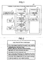
- FIG. 1 is a block diagram of the configuration of the thermal-fluid-simulation analyzing apparatus according to the first embodiment.
- a thermal-fluid-simulation analyzing apparatus 10 is a computer device that includes a communication control I/F unit 11, an input unit 12, a display unit 13, a storage unit 15, and a control unit 20.
- the communication control I/F unit 11 has a plurality of ports and controls information sent to or received from an external device.
- the communication control I/F unit 11 is connected to a computer such as an administrator device that receives a simulation result (analysis result) given by the thermal-fluid-simulation analyzing apparatus 10 and that considers countermeasures in accordance with the simulation result.
- the communication control I/F unit 11 sends the simulation result to the administrator device.
- the input unit 12 receives pieces of information and is, for example, a keyboard, a mouse, or a microphone.
- the input unit 12 receives, for example, a simulation start instruction and a simulation end instruction and sends the received instructions to the control unit 20 described later.
- the display unit 13 described later implements a pointing device function in cooperation with the mouse.
- the display unit 13 outputs various pieces of information and is, for example, a monitor, a display, a touch panel, or a speaker.
- the display unit 13 displays/outputs, for example, simulation result obtained by the thermal-fluid-simulation analyzing apparatus 10, etc.
- the storage unit 15 is, for example, a semiconductor memory, such as a random access memory (RAM), a read only memory (ROM), and a flash memory, or a storage device, such as a hard disk and an optical disk.
- the storage unit 15 stores therein data and programs for processes performed by the control unit 20.
- the storage unit 15 includes an analysis condition DB 15a and an analysis result DB 15b.
- the analysis condition DB 15a is a storage device as illustrated above, and stores therein analysis conditions.
- the stored analysis conditions are used when an execution unit 20a described later generates an analysis model.
- the analysis condition DB 15a stores therein, as items of the analysis conditions, floor information (outer shape and height), arrangement information (racks, grilles, and air conditioners), amounts of rack-generated heat, volumes of rack exhaust-air, grille information (the grille aperture ratios), cooling performances of the air conditioners, flow volumes of the air conditioners, etc.
- FIG. 2 is an example of a table of the items that are stored in the analysis condition DB.
- Some of the items are prestored by a data-center administrator or a person in charge of IT-device maintenance, the items including the floor information (outer shape and height), the arrangement information (racks, grilles, and air conditioners), the grille information (the grille aperture ratios), the cooling performances of the air conditioners, the flow volumes of the air conditioners, etc.
- the items including the floor information (outer shape and height), the arrangement information (racks, grilles, and air conditioners), the grille information (the grille aperture ratios), the cooling performances of the air conditioners, the flow volumes of the air conditioners, etc.
- the amounts of rack-generated heat and the volumes of rack exhaust-air can be prestored, it is possible to set temperature sensors and air flow sensors attached to the rack devices, etc., and obtain their actual measured values when a simulation starts.
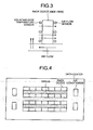
- temperature sensors may be attached to the air intake side, and air flow sensors may be attached to the air outlet side of the rack device.
- the air intake side is a side from which the cooling air is supplied to the IT devices in the rack device.
- the air outlet side is a side from which the exhaust air is discharged.
- the analysis result DB 15b is a storage device as illustrated above, and stores therein the simulation result given by the control unit 20.
- the analysis result DB 15b stores therein the simulation results in association with the date and time when the simulation is conducted and the analysis conditions of the simulation.
- the control unit 20 is, for example, an integrated circuit such as an application specific integrated circuit (ASIC) and a field programmable gate array (FPGA), or an electric circuit such as a central processing unit (CPU) or a micro processing unit (MPU).
- the control unit 20 includes an internal memory that stores therein control programs, such as operating system (OS), computer programs that define processing procedures, and data.
- control unit 20 includes the execution unit 20a, an analysis-condition collecting unit 20b, a condition extracting unit 20c, and a re-execution unit 20d and performs various processes using these units.
- the execution unit 20a generates an analysis model using the analysis conditions and conducts a thermal fluid simulation analysis for the generated analysis mode.
- the analysis conditions are conditions in simulating an air-conditioning state of a predetermined space during the thermal fluid simulation analysis.
- the execution unit 20a obtains, from the analysis condition DB 15a, the analysis conditions for the data center where the air conditioners, the grilles, and the rack devices are arranged as illustrated in FIG. 4 .
- the execution unit 20a collects the analysis conditions that include the floor information, the information about arrangement of the rack devices, the grilles, and the air conditioners, the amounts of rack-generated heat, the volumes of rack exhaust-air, the grille aperture ratios, the cooling performances of the air conditioners, the flow volumes of the air conditioners, etc.
- FIG. 4 is an exemplary plan view of an interior of the data center.
- the execution unit 20a defines (sets), using the collected analysis conditions, the shape of the data center, the heat generating conditions of the rack devices, the intake/outlet air volumes of the individual IT devices, the total intake/outlet air volume of the rack devices, the total air flow volume of the data center, etc., thereby generating an analysis model.
- the execution unit 20a then divides the analysis model into meshes as illustrated in FIG. 5 by transforming conservation equations (e.g., the Navier-Stokes equation) the air flow and the thermal transfer in the data center into finite volumes.
- the mesh division is performed using a typical finite volume method and its detailed description is omitted.
- FIG. 5 is a schematic diagram of the data center that is divided into meshes using the finite volume method.
- the execution unit 20a performs coupling so that one parameter of the conservation equation, e.g., the Navier-Stokes equation, depends on another parameter or a value nearby and then performs a finite iterative calculation repeatedly until the error of the conservation equation decreases to an allowable level, thereby causing the solutions to converge and thus solving the conservation equation. More particularly, the execution unit 20a causes the solutions of the Navier-Stokes equation to converge using a widely-known splitting method, for example, a SIMPLE algorism.
- a widely-known splitting method for example, a SIMPLE algorism.
- the execution unit 20a calculates, using the conservation equation, both the flow velocity in the x axis of the mesh-divided space and the flow velocity in the y axis.
- the execution unit 20a then calculates the pressure in the mesh-divided space, updates the flow velocity and the density for the conservation equation, and calculates the temperature using another equation, e.g., the heat equation.
- the execution unit 20a determines whether an error between a threshold and a boundary value that is determined according to the calculated flow velocities and the calculated temperature is within an allowable range, i.e., whether a converged solution is obtained for the boundary value.
- the execution unit 20a completes the simulation. If a converged solution is not obtained for the boundary value, the execution unit 20a repeats the above simulation until a converged solution is obtained for the boundary value. After the simulation is completed, the administrator, etc., analyzes the situation using the simulation result.
- the execution unit 20a uses Navier-Stokes equations that includes a mass conservation equation represented by Equation (1), momentum conservation equations represented by Equations (2) and (3), and an energy conservation equation represented by Equation (4).
- ⁇ is a closed region in the space of the data center or the volume of the closed region;
- A is the boundary surface of the region ⁇ adjacent to the outside or the area of the boundary surface.
- n is the unit vector; and
- ⁇ is the mass of fluid per unit area in the data center;
- ⁇ is the viscosity coefficient that is the ratio between the shearing stress and the velocity gradient; and
- p is the value of pressure on the data center.
- E is the amount of energy in the data center;
- T is the temperature.
- k is the thermal conductivity indicative of the ratio between the thermal flux and the thermal gradient (Fourier's law).
- S is the source term (pressure term) indicative of the pressure in the data center, i.e., in the meshes.
- the execution unit 20a calculates, using the momentum conservation equations represented by Equations (2) and (3), a "flow velocity V" in each of the x axis, the y axis, and the z axis of the mesh-divided data center. More particularly, the execution unit 20a substitutes the known pressure p in Equations (2) and (3), thereby calculating a predictive value of the flow velocity V.
- the execution unit 20a creates, using the mass conservation equation represented by Equation (1) and the momentum conservation equation represented by Equation (2), an equation that is to be satisfied by both a correction amount for the pressure and a correction amount for the flow velocity.
- the execution unit 20a then expresses the correction amount for the flow velocity depending on the correction amount for the pressure, calculates the pressure equation with only the correction amount for the pressure being an unknown, updates the pressure and the flow velocity, and calculates the pressure (pressure field) and the flow velocity (flow velocity field) that satisfy both the momentum conservation equation and the mass conservation equation. In other words, the execution unit 20a calculates both the correction value for the pressure and the correction value for the flow velocity and updates the flow velocity V that is predicted using the known pressure p.
- the execution unit 20a calculates the energy E using the mass conservation equations represented by Equations (5) and (6), the Newton's second law of motion, the thermodynamic law, etc.
- the execution unit 20a determines whether an error between the threshold and the boundary value that is determined according to the calculated flow velocities and the calculated temperature is within an allowable range, i.e., whether a converged solution is obtained for the boundary value. If a converged solution is obtained for the boundary value, the execution unit 20a ends the simulation. If a converged solution is not obtained for the boundary value, the execution unit 20a repeats the above simulation until a converged solution is obtained for the boundary value.
- the execution unit 20a can calculate a simulation result indicating, for example, how the temperature in the data center changes after the simulation has been conducted.
- the execution unit 20a displays/outputs the calculated simulation result on/to the display unit 13 and stores the calculated simulation result in the analysis result DB 15b.
- the analysis-condition collecting unit 20b collects the analysis conditions at that point of time. For example, one hour after the thermal fluid simulation analysis is conducted, the analysis-condition collecting unit 20b collects the analysis conditions at that point of time that include the floor information, the arrangement information, the amounts of rack-generated heat, the volumes of rack exhaust-air, the grille aperture ratios, the cooling performances of the air conditioners, the flow volumes of the air conditioners, etc.
- the analysis-condition collecting unit 20b collects, for example, information that is prestored by the data-center administrator or the person in charge of IT-device maintenance and the actual values measured by the temperature sensors and the air flow sensors. The period can be set appropriately by the administrator, etc.
- the analysis-condition collecting unit 20b then outputs the collected analysis conditions to the condition extracting unit 20c.
- the condition extracting unit 20c extracts boundary conditions from the analysis conditions that are collected by the analysis-condition collecting unit 20b after the predetermined period after the thermal fluid simulation analysis has been conducted.
- the boundary conditions are conditions that have changed relative to the corresponding conditions used for the simulation conducted by the execution unit 20a.
- the condition extracting unit 20c compares the analysis conditions collected by the analysis-condition collecting unit 20b with the analysis conditions used for the thermal fluid simulation analysis by the execution unit 20a, and extracts different conditions as the boundary conditions.
- the condition extracting unit 20c then outputs the extracted boundary conditions to the re-execution unit 20d.
- condition extracting unit 20c determines through the comparison that the "amount of rack-generated heat" and the "volume of rack exhaust air” are updated, the condition extracting unit 20c outputs the actual values of the "amount of rack-generated heat” and the "volume of rack exhaust air” measured using the sensors, etc., to the re-execution unit 20d.
- the re-execution unit 20d selects a region corresponding to the boundary conditions that are extracted by the condition extracting unit 20c from regions of the analysis model that is generated by the execution unit 20a, updates the selected region with the boundary conditions, and conducts the thermal fluid simulation analysis for the updated analysis model. More particularly, when the boundary conditions are extracted by the condition extracting unit 20c, the re-execution unit 20d selects a region that is defined by the boundary conditions from the regions of the analysis model that is generated by the execution unit 20a. The re-execution unit 20d then re-defines the selected region on the analysis model that is generated by the execution unit 20a, i.e., updates the selected region with the boundary conditions that are extracted by the condition extracting unit 20c. After that, the re-execution unit 20d conducts the thermal fluid simulation analysis for the analysis model updated with the boundary conditions.
- the re-execution unit 20d need not to generate a new analysis model by collecting the analysis conditions and to perform mesh division. As illustrated in FIG. 6 , the re-execution unit 20d updates the existing analysis model (in the above example, the analysis model generated one hour ago) and its meshes with only some analysis conditions different from the previous analysis conditions and conducts the thermal fluid simulation analysis for the updated analysis model and the updated meshes.
- FIG. 6 is a schematic diagram that illustrates the re-defined region that is to be simulated.
- the re-execution unit 20d can calculate a simulation result indicating, for example, how the temperature in the data center changes after the simulation has been conducted.
- the re-execution unit 20d displays/outputs the calculated simulation result on/to the display unit 13 and stores the calculated simulation result in the analysis result DB 15b.
- the re-execution unit 20d re-defines the analysis model by updating only the "amount of rack-generated heat” and the "volume of rack exhaust air” that are determined as the analysis conditions different from the corresponding analysis conditions one hour ago and conducts the thermal fluid simulation analysis for the updated analysis model.
- the re-execution unit 20d changes the value of the "amount of rack-generated heat” and the value of the "volume of rack exhaust air” of the analysis conditions one hour ago to the value of the "amount of rack-generated heat” and the value of the "volume of rack exhaust air” that are newly collected one hour after the simulation is conducted, respectively.
- the re-execution unit 20d conducts the thermal fluid simulation analysis for the updated analysis model.
- thermal-fluid-simulation analyzing apparatus The processes performed by the thermal-fluid-simulation analyzing apparatus according to the first embodiment are described below with reference to FIG. 7 .
- FIG. 7 is a flowchart of the processes performed by the thermal-fluid-simulation analyzing apparatus according to the first embodiment.
- Step S101 when a simulation start instruction is received by the input unit 12, etc., (Yes at Step S101), the execution unit 20a collects the analysis conditions (Step S102).
- the execution unit 20a generates an analysis model by defining the collected analysis conditions (Step S103). Furthermore, the execution unit 20a divides the generated analysis model into meshes by transforming the conservation equations (e.g., the Navier-Stokes equation) of the air flow and the thermal transfer in the generated analysis model into finite volumes (Step S104).
- the conservation equations e.g., the Navier-Stokes equation
- the execution unit 20a conducts the thermal flow simulation that involves performing coupling with the conservation equation, e.g., the Navier-Stokes equation, and then performing a finite iterative calculation repeatedly until the error of the conservation equation decreases to an allowable level, thereby causing the solutions to converge and thus solving the conservation equation (Step S105).
- the execution unit 20a displays/outputs the simulation result on/to the display unit 13 and stores the simulation result in the analysis result DB 15b (Step S106).
- the analysis-condition collecting unit 20b collects the analysis conditions at this point of time (Step S108).
- the condition extracting unit 20c extracts the boundary conditions from the analysis conditions that are collected by the analysis-condition collecting unit 20b after the predetermined period after the thermal fluid simulation analysis has been conducted (Step S109).
- the re-execution unit 20d selects a region corresponding to the boundary conditions that are extracted by the condition extracting unit 20c from the regions of the analysis model that is generated by the execution unit 20a and updates the selected region with the boundary conditions (Step S110).
- the re-execution unit 20d conducts the thermal fluid simulation analysis for the analysis model updated only with the boundary conditions (Step S111). The processes at Step S106 and the subsequent steps are repeated until a device end instruction or a simulation end instruction is received by the input unit 12, etc.
- the previous conditions are available at the start of a new thermal fluid simulation, it is possible to conduct the new thermal fluid simulation for the updated analysis model that is generated by re-defining only some conditions that have changed relative to the corresponding previous conditions. Therefore, for example, it takes shorter time to simulate the air-conditioning state in the data center using the thermal fluid simulation, which enables a quick analysis of the current situation.
- the number of iterations of the default calculation in other words, the number of the thermal fluid simulations using the default values is about 200, as illustrated in FIG. 8 .
- the number of iterations of the subsequent calculation decreases to about 50, because the analysis is conducted for the updated analysis model that is generated by re-defining only some conditions that have changed relative to the corresponding previous conditions.
- the conventional simulator repeats the same number (about 200 in this example) of iterations for the subsequent calculation as it is repeated for the default calculation; therefore, it takes a significantly long time for one simulation.
- the thermal-fluid-simulation analyzing apparatus disclosed in the present application analyzes the updated analysis model that is generated by re-defining only some conditions that have changed relative to the corresponding previous conditions during the calculation subsequent to the default calculation, i.e., conducts the thermal fluid simulation for the updated conditions, which significantly reduces the number of iterations of the calculation. As a result, it takes shorter time to simulate the air-conditioning state in the data center using the thermal fluid simulation, which enables a quick analysis of the situation.
- FIG. 8 is a graph of an example of a convergence curve when the simulation is re-conducted by re-defining only the boundary conditions.
- the configuration is not limited thereto. It can be configured to re-conduct the simulation when an alarm is generated because, for example, the temperature in the data center increases to a threshold or higher or because the temperature sensors or the air flow sensors that are attached to the rack devices detect an abnormal temperature or an abnormal air flow.
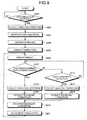
- FIG. 9 is a flowchart of the processes performed by a thermal-fluid-simulation analyzing apparatus according to the second embodiment
- FIG. 10 is an example of an association table that contains the types of alarms and the items to be re-defined.
- Steps S201 to S211 illustrated in FIG. 9 are the same as the processes of Steps S101 to S111 described in the first embodiment; therefore, the same description is not repeated. Only the processes in Steps S212 to S214 will be described because they are different from the processes in the first embodiment.
- the thermal-fluid-simulation analyzing apparatus 10 determines whether an alarm is detected by the sensors (Step S212).
- the thermal-fluid-simulation analyzing apparatus 10 obtains the actual values measured by the temperature sensors and the air flow sensors in the data center or the temperature sensors and the air flow sensors attached to each of the rack devices and determines whether the actual measured values are higher than the predetermined thresholds.
- the thermal-fluid-simulation analyzing apparatus 10 obtains the actual measured values using the sensors and determines whether a problem occurs, the configuration is not limited thereto. It can be configured to, for example, output an alarm to the thermal-fluid-simulation analyzing apparatus 10 when the temperature sensors detect a temperature higher than the threshold or when the air flow sensors detect an air volume higher than the threshold.
- the analysis-condition collecting unit 20b of the thermal-fluid-simulation analyzing apparatus 10 collects the analysis conditions in accordance with the type of the alarm (Step S213).
- the condition extracting unit 20c extracts the analysis conditions collected by the analysis-condition collecting unit 20b as the boundary conditions (Step S214).
- the process control returns to Step S207 and the subsequent processes are performed.
- the analysis-condition collecting unit 20b stores in the storage unit 15, for example, the database as illustrated in FIG. 10 that contains the types of alarms and the items to be re-defined in an associated manner. When an alarm is detected, the analysis-condition collecting unit 20b determines, by referring to FIG. 10 , the items to be re-defined by the type of the detected alarm. If, for example, a temperature alarm is detected by a temperature sensor attached to the air intake side of a rack device, the analysis-condition collecting unit 20b determines the "volume of rack exhaust air", the "cooling performance of the air conditioner", and the "flow volume of the air conditioner” to be the items to be re-defined and obtains the actual measured values of each of the items to be re-defined from the sensors, the administrator, etc.
- the analysis-condition collecting unit 20b determines the "arrangement information" and the "flow volume of the air conditioner" to be the items to be re-defined and obtains the actual measured values of each of the items to be re-defined.
- the condition extracting unit 20c extracts the items to be re-defined as the boundary conditions.
- the condition extracting unit 20c extracts the actual measured values of the "volume of rack exhaust air", the "cooling performance of the air conditioner", the "flow volume of the air conditioner” as the boundary conditions.
- the condition extracting unit 20c extracts the actual measured values of the "arrangement information" and the "flow volume of the air conditioner” as the boundary conditions.
- the re-execution unit 20d selects a region corresponding to the boundary conditions that are extracted by the condition extracting unit 20c from regions of the analysis model that is generated by the execution unit 20a and updates the selected region with the boundary conditions (Step S210).
- the re-execution unit 20d conducts the thermal fluid simulation analysis for the analysis model updated only with the boundary conditions (Step S211).
- the thermal-fluid-simulation analyzing apparatus 10 repeats the processes at Step S206 and the subsequent steps until a device end instruction or a simulation end instruction is received by the input unit 12, etc.
- the thermal-fluid-simulation analyzing apparatus 10 when a problem occurs and an alarm is generated, the thermal-fluid-simulation analyzing apparatus 10 obtains the actual measured values (of a mesh region) of the analysis conditions subjected to the problem indicated by the alarm. The thermal-fluid-simulation analyzing apparatus 10 then updates (re-defines) the analysis model with the actual measured values of the analysis conditions that are obtained in accordance with the alarm and conducts the thermal fluid simulation analysis for the updated (re-defined) analysis model. Therefore, the thermal fluid simulation is conducted in a short time after the occurrence of the problem, which enables quick analysis of the abnormal situation and quick selection of a countermeasure.
- the thermal-fluid-simulation analyzing apparatus 10 disclosed in the present application can display the simulation result on the display unit 13. Furthermore, the thermal-fluid-simulation analyzing apparatus 10 can be configured to compare a simulation result with its immediately previous simulation result and display a result of the comparison on the display unit 13.
- FIG. 11 is a flowchart of the processes performed by a thermal-fluid-simulation analyzing apparatus according to a third embodiment.
- Steps S301 to S311 illustrated in FIG. 11 are the same as the processes of Steps S101 to S111 described in the first embodiment. Moreover, the processes of Steps S314 to S316 are the same as the processes of Steps S212 to S214 described in the second embodiment. Therefore, the same processes as those in the first embodiment and the second embodiment will not be described and only the processes of Steps S312 to S313 will be described because they are different from the processes in the first embodiment and the second embodiment.
- the re-execution unit 20d of the thermal-fluid-simulation analyzing apparatus 10 compares a simulation result given by the thermal fluid simulation analysis for the analysis model updated only with the boundary conditions with a simulation result given by the previous simulation (Step S312).
- the re-execution unit 20d displays/outputs a result of the comparison on/to the display unit 13 and stores the result of the comparison in the analysis result DB 15b (Step S313).
- the thermal-fluid-simulation analyzing apparatus 10 repeats the processes at Step S306 and the subsequent steps until a device end instruction or a simulation end instruction is received by the input unit 12, etc.
- the re-execution unit 20d compares the simulation result with the previous simulation result and extracts, as a result of the comparison, a temperature distribution, a flow velocity distribution, or an air volume distribution, etc, of the space.
- the result of the comparison can include not only the distributions but also, for example, difference between the current simulation and the previous simulation, temporal change of the difference, etc.
- the thermal-fluid-simulation analyzing apparatus can display a result of the comparison with the previous simulation; therefore, the administrator, etc., can grasp, for example, conditions or regions that have changed significantly and obtain information indicative of a sign of a problem at an early stage. As a result, it is possible to prevent occurrence of a problem in, for example, the data center.
- the thermal-fluid-simulation analyzing apparatus 10 disclosed in the present application can be configured to compare a simulation result with the actual measured value and use a result of the comparison as feedback so that the thermal-fluid-simulation analyzing apparatus 10 can perform stable air-conditioning control.
- FIG. 12 is a flowchart of the processes performed by a thermal-fluid-simulation analyzing apparatus according to the fourth embodiment
- FIG. 13 is a graph that is used to compare simulation results with the actual measured values.
- Step S401 when the data center is placed in operation (Step S401), the thermal-fluid-simulation analyzing apparatus 10 conducts the thermal fluid simulation in the above-described manner (Step S402).
- the thermal-fluid-simulation analyzing apparatus 10 obtains the actual measured value of the temperature from the sensors, etc., in the data center or attached to the rack devices every, for example, five minutes and compares the actual measured value with a predicted value of the corresponding point of time that is predicted and obtained as a simulation result (Step S403). If a result of the comparison is outside an allowable range (Yes at Step S404), the thermal-fluid-simulation analyzing apparatus 10 generates an alarm (Step S405) and sends, as feedback, a message indicating a bad condition to the administrator device, etc. (Step S406).
- the thermal-fluid-simulation analyzing apparatus 10 repeats the processes at Step S401 and the subsequent steps until a device end instruction or a simulation end instruction is received by the input unit 12, etc. On the other hand, if the result of the comparison is within the allowable range (No at Step S404), the thermal-fluid-simulation analyzing apparatus 10 repeats the processes at Step S401 and the subsequent steps.
- the thermal-fluid-simulation analyzing apparatus 10 compares the predicted value indicative of an increase in temperature of each rack device that is obtained as a simulation result with the actual value measured using the temperature sensor attached to each rack device. In this example, because the rack number A and the rack number K are outside the allowable range, the thermal-fluid-simulation analyzing apparatus 10 determines that it is in a bad condition and generates an alarm. Furthermore, because the rack numbers A and K are outside the allowable range and it is determined to be in a bad condition, the thermal-fluid-simulation analyzing apparatus 10 sends a message to the administrator device, etc., instructing to take a countermeasure to avoid the danger.
- thermal-fluid-simulation analyzing apparatus 10 can be implemented according to embodiments other than the above-described embodiments. Some of the other embodiments within the scope of the present application will be described below as a fifth embodiment.
- the simulation is conducted by calculating the conservation equations, e.g., the Navier-Stokes equation, of the air flow and the thermal transfer using a splitting method such as the SIMPLE algorism.
- the calculation method is not limited thereto.
- any analysis programs and algorisms can be used for the calculation as long as the thermal fluid simulation analysis is conducted.
- the trigger for simulation is the lapse of a predetermined period after the first simulation has been conducted or generation of an alarm.
- the trigger is not limited thereto.
- the thermal-fluid-simulation analyzing apparatus 10 can be configured, for example, to conduct the thermal fluid simulation when the time comes at which it is predicted that the alarm is generated on the basis of the simulation result. In other words, the thermal-fluid-simulation analyzing apparatus 10 can set the time when it is predicted that an alarm is generated on the basis of the simulation result as a trigger for the simulation.
- the simulation result is compared with the actual measured value and a result of the comparison is output to the display unit 13, etc.
- the target to be compared is not limited thereto.
- the thermal-fluid-simulation analyzing apparatus 10 can be configured to, for example, compare the simulation result with indicators, etc., that include the coefficient of performance (COP), the power usage effectiveness (PUE), etc., and output a result of the comparison to the display unit 13, etc. This improves the efficiency of energy used for air conditioning in the space to be simulated.
- COP coefficient of performance
- PUE power usage effectiveness
- constituent elements of the devices illustrated in the drawings are merely conceptual, and need not be physically configured as illustrated.
- the constituent elements, as a whole or in part, can be separated or integrated either functionally or physically based on various types of loads or use conditions (for example, the execution unit 20a and the re-execution unit 20d can be implemented as one unit).
- the processing procedures, the control procedures, specific names, various data, and information including parameters described in the above embodiments or illustrated in the drawings (for example, FIGS. 2 , 10 , etc.) can be changed as appropriately unless otherwise specified.
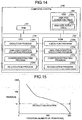
- FIG. 14 is a block diagram of an example of a computer system that that executes a thermal-fluid-simulation analysis program.
- a computer system 100 includes a RAM 101, an HDD 102, a ROM 103, and a CPU 104.
- the ROM 103 prestores therein computer programs that are used to implement the same functions as those of the above embodiments. More particularly, as illustrated in FIG. 14 , an execution program 103a, an analysis-condition collecting program 103b, a condition extracting program 103c, and a re-execution program 103d are prestored in the ROM 103.
- the CPU 104 reads and executes these computer programs 103a to 103d. Then, as illustrated in FIG. 14 , an execution process 104a, an analysis-condition collecting process 104b, a condition extracting process 104c, and a re-execution process 104d are implemented, respectively.
- the execution process 104a corresponds to the execution unit 20a illustrated in FIG. 1
- the analysis-condition collecting process 104b corresponds to the analysis-condition collecting unit 20b
- the condition extracting process 104c corresponds to the condition extracting unit 20c
- the re-execution process 104d corresponds to the re-execution unit 20d.
- the HDD 102 has an analysis condition table 102a and an analysis result table 102b.
- the analysis condition table 102a contains the analysis conditions and is used for generating the analysis model.
- the analysis result table 102b contains simulation results.
- the analysis condition table 102a corresponds to the analysis condition DB 15a illustrated in FIG. 1
- the analysis result table 102b corresponds to the analysis result DB 15b.
- the above-described computer programs 103a to 103d need not be stored in the ROM 103.
- they can be stored in a "portable physical medium” insertable to the computer system 100, such as a flexible disk (FD), a CD-ROM, an MO disk, a DVD disk, a magnetic optical disk, or an IC card.
- FD flexible disk
- CD-ROM compact disc-read only memory
- MO disk compact disc-read only memory
- DVD digital versatile disk
- a magnetic optical disk or an IC card
- a "stationary physical medium” such as an internal or external hard disk drive (HDD) of the computer system 100.
- HDD hard disk drive
- they can be stored in "another computer system” that is connected to the computer system 100 via the public line, the Internet, a LAN, a WAN, or the like.
- the computer system 100 reads the computer programs from the media and the external computer system and executes the read computer programs.
- the time taken is decreased for a thermal fluid simulation that is performed to analyze the air-conditioning state and thus a quick analysis of the current situation may be enabled.
Landscapes
- Engineering & Computer Science (AREA)
- Physics & Mathematics (AREA)
- Theoretical Computer Science (AREA)
- Geometry (AREA)
- General Physics & Mathematics (AREA)
- Computer Hardware Design (AREA)
- Evolutionary Computation (AREA)
- General Engineering & Computer Science (AREA)
- Mathematical Analysis (AREA)
- Pure & Applied Mathematics (AREA)
- Mathematical Optimization (AREA)
- Architecture (AREA)
- Structural Engineering (AREA)
- Computational Mathematics (AREA)
- Civil Engineering (AREA)
- Algebra (AREA)
- Computing Systems (AREA)
- Fluid Mechanics (AREA)
- Mathematical Physics (AREA)
- Management, Administration, Business Operations System, And Electronic Commerce (AREA)
- Air Conditioning Control Device (AREA)
- Software Systems (AREA)
Abstract
A thermal-fluid-simulation analyzing apparatus (10) includes an execution unit (20a) that generates an analysis model using analysis conditions and conducts a first thermal fluid simulation analysis based on the generated analysis model, an analysis-condition collecting unit (20b) that collects analysis conditions when a predetermined period passes after the first thermal fluid simulation analysis by the execution unit (20a), a condition extracting unit (20c) that extracts a boundary condition from the analysis conditions collected by the analysis-condition collecting unit (20b), and a re-execution unit (20d) that selects a region corresponding to the boundary condition extracted by the condition extracting unit (20c) from regions of the analysis model generated by the execution unit (20a), updates the selected region with the boundary condition, and conducts a second thermal fluid simulation analysis for the updated analysis model.
Description
- The embodiments discussed herein are directed to thermal-fluid-simulation analyzing apparatuses.
- In data centers where there are information technology (IT) devices, such as computers, servers, and routers, accommodated in rack devices, heated air is taken out and cooling air is taken in using air conditioners so that the IT devices are cooled down.
- In recent years, the temperature in the data centers tend to become high because the IT devices are closely arranged in rack devices and the consumed power of the data centers have increased. As a result, sometimes the IT devices are not cooled down sufficiently, which causes problems. When the temperature distribution in data centers is examined, it is known that the IT devices and the rack devices are arranged at different locations in different installation environments, and that the amount of heat generated by the central processing units (CPUs) in the IT devices varies, and the amount of heat generated by the rack devices varies. Therefore, some IT devices are not cooled down, and heated beyond a permissible temperature. Furthermore, such an increase in the temperature in a data center may cause a malfunction of the air conditioners that supply the cooling air; for example, abnormal operation or abnormal stop of the air conditioner may occur.
- To predict the occurrence of such an abnormal condition, a sensor or the like is employed (see, for example, Japanese Laid-open Patent Publication No.
2008-034715 08-095672 - In view of this drawback, a technique utilizing thermal-fluid simulation is employed for predicting an abnormal phenomenon other than the above-described prediction technique utilizing the sensor. Specifically, when a temperature sensor, an air flow sensor, or the like detects abnormal temperature, abnormal air flow, or the like in the data center, various actions are taken: for example, the measurement data such as temperature data is analyzed for identifying the problem; the situation is assessed based on a simulation; and a countermeasure is taken.
- For example, a simulator, which conducts a thermal fluid simulation, performs a series of processes to assess the situation based on a thermal-fluid simulation: for example, the simulator performs a series of processes for collecting an analysis conditions, formulating an analysis model, generating a mesh, executing calculations, and analyzing a result.
- Each of these processes is described in detail below.
- The simulator first collects analysis conditions that include floor information, information about the arrangement of rack devices, grilles, and air conditioners, amounts of rack-generated heat, volumes of rack exhaust-air, grille aperture ratios, cooling performances of the air conditioners, and flow volumes of the air conditioners. The simulator obtains the analysis conditions from, for example, a database which is created by an administrator and which contains information about arrangement of devices inside the data center. The simulator then performs model shaping, heat-generating-condition setting, and air-flow setting, to generate an analysis model.
- After that, the simulator divides the analysis model into meshes by transforming conservation equations (e.g., the Navier-Stokes equation) of the air flow and the thermal transfer in the data center into finite volumes. If the space to be analyzed is large or if a highly accurate simulation is needed, the number of meshes is increased and the number of calculations is increased.
- After that, the simulator performs coupling so that one parameter of the conservation equation, e.g., the Navier-Stokes equation, depends on another parameter or a nearby value and then performs a finite iterative calculation repeatedly until the error of the conservation equation decreases to an allowable level, thereby causing the solutions to converge and thus solving the conservation equation. More specifically, the simulator causes the solutions of the Navier-Stokes equation to converge using a widely-known splitting method, for example, Semi-Implicit Method for Pressure Linked Equations (SIMPLE) algorism.
- For example, after setting the default values in the conservation equation, the simulator calculates, using the conservation equation, both the flow velocity in the x axis of the mesh-divided space and the flow velocity in the y axis. The simulator then calculates the pressure in the mesh-divided space, updates the flow velocity and the density for the conservation equation, and calculates the temperature, for example, using another equation, e.g., the heat equation. The simulator determines whether an error between a threshold and a boundary value that is determined according to the calculated flow velocities and the calculated temperature is within an allowable range, i.e., whether a converged solution is obtained for the boundary value. If a converged solution is obtained for the boundary value, the simulator ends the simulation. If a converged solution is not obtained for the boundary value, the simulator repeats the above simulation until a converged solution is obtained for the boundary value. After the simulation ends, the administrator, etc., assesses the current situation using the simulation result.
- However, in the conventional technique described above, it takes a significantly long time for the simulation that is conducted to analyze the air-conditioning state in the data center; therefore, analysis of the situation is not made quickly. When a problem occurs in the data center, the situation can be analyzed and assessed only after the series of processes described above is performed. Then, it takes a significantly long time to analyze the situation and to take countermeasures for the problem.
- For example, assume that it is necessary for the conventional simulator to repeat the finite iterative calculation about 200 times until the error of the conservation equation decreases to an allowable level, as illustrated in
FIG. 15 . In this case, when a temperature problem occurs in the data center, the conventional simulator initializes previously calculated results after collecting the analysis conditions and generating the analysis model as describe earlier. Thereafter, the conventional simulator performs a calculation about 200 times to create the information for analyzing the situation. Therefore, it takes a long time for the administrator, etc., to analyze the situation and, even longer time to take countermeasures for the problem. - Accordingly, it is desirable to provide a thermal-fluid-simulation analyzing apparatus that decreases the time taken for a thermal fluid simulation that is performed to analyze the air-conditioning state and thus enables a quick analysis of the situation.
- According to an aspect of an embodiment of the invention, a thermal-fluid-simulation analyzing apparatus includes: an execution unit that generates an analysis model using analysis conditions and that conducts a first thermal fluid simulation analysis based on the generated analysis model, the analysis condition being a condition in a thermal fluid simulation analysis according to which an air conditioning state in a predetermined space is simulated; an analysis-condition collecting unit that, when a predetermined period passes after the first thermal fluid simulation analysis by the execution unit, collects analysis conditions; a condition extracting unit that extracts a boundary condition from the analysis conditions that are collected by the analysis-condition collecting unit when the predetermined period passes after the first thermal fluid simulation analysis, the boundary condition being an analysis condition that has changed relative to a corresponding analysis condition used for the first thermal fluid simulation analysis; and a re-execution unit that selects a region corresponding to the boundary condition extracted by the condition extracting unit from regions of the analysis model generated by the execution unit, updates the selected region with the boundary condition, and conducts a second thermal fluid simulation analysis for the updated analysis model.
- Preferred features of the present invention will now be described, purely by way of example, with reference to the accompanying drawings, in which:-
-
FIG. 1 is a block diagram of the configuration of a thermal-fluid-simulation analyzing apparatus according to a first embodiment; -
FIG. 2 is an example of a table of items that are stored in an analysis condition DB; -
FIG. 3 is a side view of an example of a rack device, the rack device having temperature sensors and air flow sensors attached; -
FIG. 4 is an exemplary plan view of an interior of a data center; -
FIG. 5 is a schematic diagram of a data center that is divided into meshes using a finite volume method; -
FIG. 6 is a schematic diagram that illustrates a re-defined region that is a target of simulation; -
FIG. 7 is a flowchart of processes performed by the thermal-fluid-simulation analyzing apparatus according to the first embodiment; -
FIG. 8 is a graph of an example of a convergence curve when the simulation is re-conducted by re-defining only boundary condition; -
FIG. 9 is a flowchart of processes performed by a thermal-fluid-simulation analyzing apparatus according to a second embodiment; -
FIG. 10 is an example of an association table that contains types of alarms and items to be re-defined; -
FIG. 11 is a flowchart of processes performed by a thermal-fluid-simulation analyzing apparatus according to a third embodiment; -
FIG. 12 is a flowchart of processes performed by a thermal-fluid-simulation analyzing apparatus according to a fourth embodiment; -
FIG. 13 is a graph that is used to compare simulation results with actual measured values; -
FIG. 14 is a block diagram of an example of a computer system that executes a thermal fluid simulation analysis program; and -
FIG. 15 is a graph of an example of a convergence curve when a conventional thermal fluid simulation analysis is conducted. - Preferred embodiments of the present invention will be explained with reference to accompanying drawings. It is noted that the present invention is not limited to the preferred embodiments.
- Embodiments of a thermal-fluid-simulation analyzing apparatus according to the present invention are described in detail below with reference to the accompanying drawings. The configuration of a thermal-fluid-simulation analyzing apparatus according to a first embodiment, processes performed by the thermal-fluid-simulation analyzing apparatus, and effects of the first embodiment are described in the following sections.
- The thermal-fluid-simulation analyzing apparatus disclosed in the present application conducts a thermal fluid simulation analysis by simulating an air-conditioning state of a predetermined space, for example, an air-conditioning state of a data center. The thermal-fluid-simulation analyzing apparatus can be used for any spaces other than the interior of data centers where temperature adjustment and air-flow adjustment are needed, such as movie houses and agricultural facilities.
- A data center includes a rack device that accommodates an information technology (IT) device, an air conditioner that takes in exhaust air from the IT devices and supplies cooling air to a underfloor space, for example, and a grille that circulates the cooling air from the underfloor space to a space above the floor level. The IT device takes in the cooling air supplied from the air conditioner, cools down their internal electronics, etc., and discharges the heated air to a room space. Therefore, the temperature in the data center is kept at a relatively low level for cooling the IT-device.
- Configuration of the thermal-fluid-simulation analyzing apparatus
- The configuration of the thermal-fluid-simulation analyzing apparatus according to the first embodiment is described below with reference to
FIG. 1. FIG. 1 is a block diagram of the configuration of the thermal-fluid-simulation analyzing apparatus according to the first embodiment. - As illustrated in
FIG. 1 , a thermal-fluid-simulation analyzing apparatus 10 is a computer device that includes a communication control I/F unit 11, aninput unit 12, adisplay unit 13, astorage unit 15, and a control unit 20. - The communication control I/
F unit 11 has a plurality of ports and controls information sent to or received from an external device. For example, the communication control I/F unit 11 is connected to a computer such as an administrator device that receives a simulation result (analysis result) given by the thermal-fluid-simulation analyzing apparatus 10 and that considers countermeasures in accordance with the simulation result. The communication control I/F unit 11 sends the simulation result to the administrator device. - The
input unit 12 receives pieces of information and is, for example, a keyboard, a mouse, or a microphone. Theinput unit 12 receives, for example, a simulation start instruction and a simulation end instruction and sends the received instructions to the control unit 20 described later. Thedisplay unit 13 described later implements a pointing device function in cooperation with the mouse. - The
display unit 13 outputs various pieces of information and is, for example, a monitor, a display, a touch panel, or a speaker. Thedisplay unit 13 displays/outputs, for example, simulation result obtained by the thermal-fluid-simulation analyzing apparatus 10, etc. - The
storage unit 15 is, for example, a semiconductor memory, such as a random access memory (RAM), a read only memory (ROM), and a flash memory, or a storage device, such as a hard disk and an optical disk. Thestorage unit 15 stores therein data and programs for processes performed by the control unit 20. Thestorage unit 15 includes ananalysis condition DB 15a and ananalysis result DB 15b. - The
analysis condition DB 15a is a storage device as illustrated above, and stores therein analysis conditions. The stored analysis conditions are used when anexecution unit 20a described later generates an analysis model. As illustrated inFIG. 2 , theanalysis condition DB 15a stores therein, as items of the analysis conditions, floor information (outer shape and height), arrangement information (racks, grilles, and air conditioners), amounts of rack-generated heat, volumes of rack exhaust-air, grille information (the grille aperture ratios), cooling performances of the air conditioners, flow volumes of the air conditioners, etc.FIG. 2 is an example of a table of the items that are stored in the analysis condition DB. - Some of the items are prestored by a data-center administrator or a person in charge of IT-device maintenance, the items including the floor information (outer shape and height), the arrangement information (racks, grilles, and air conditioners), the grille information (the grille aperture ratios), the cooling performances of the air conditioners, the flow volumes of the air conditioners, etc. Moreover, although both the amounts of rack-generated heat and the volumes of rack exhaust-air can be prestored, it is possible to set temperature sensors and air flow sensors attached to the rack devices, etc., and obtain their actual measured values when a simulation starts.
- As illustrated in
FIG. 3 , temperature sensors may be attached to the air intake side, and air flow sensors may be attached to the air outlet side of the rack device. The air intake side is a side from which the cooling air is supplied to the IT devices in the rack device. The air outlet side is a side from which the exhaust air is discharged. With this configuration, data is obtained that includes the temperature of the cooling air supplied to the IT devices and the volume of the exhaust air discharged from the IT devices.FIG. 3 is a side view of an example of the rack device including the temperature sensors and the air flow sensors. - The
analysis result DB 15b is a storage device as illustrated above, and stores therein the simulation result given by the control unit 20. For example, theanalysis result DB 15b stores therein the simulation results in association with the date and time when the simulation is conducted and the analysis conditions of the simulation. - The control unit 20 is, for example, an integrated circuit such as an application specific integrated circuit (ASIC) and a field programmable gate array (FPGA), or an electric circuit such as a central processing unit (CPU) or a micro processing unit (MPU). The control unit 20 includes an internal memory that stores therein control programs, such as operating system (OS), computer programs that define processing procedures, and data. Furthermore, the control unit 20 includes the
execution unit 20a, an analysis-condition collecting unit 20b, acondition extracting unit 20c, and are-execution unit 20d and performs various processes using these units. - The
execution unit 20a generates an analysis model using the analysis conditions and conducts a thermal fluid simulation analysis for the generated analysis mode. The analysis conditions are conditions in simulating an air-conditioning state of a predetermined space during the thermal fluid simulation analysis. - More specifically, the
execution unit 20a obtains, from theanalysis condition DB 15a, the analysis conditions for the data center where the air conditioners, the grilles, and the rack devices are arranged as illustrated inFIG. 4 . For example, theexecution unit 20a collects the analysis conditions that include the floor information, the information about arrangement of the rack devices, the grilles, and the air conditioners, the amounts of rack-generated heat, the volumes of rack exhaust-air, the grille aperture ratios, the cooling performances of the air conditioners, the flow volumes of the air conditioners, etc.FIG. 4 is an exemplary plan view of an interior of the data center. - After that, the
execution unit 20a defines (sets), using the collected analysis conditions, the shape of the data center, the heat generating conditions of the rack devices, the intake/outlet air volumes of the individual IT devices, the total intake/outlet air volume of the rack devices, the total air flow volume of the data center, etc., thereby generating an analysis model. Theexecution unit 20a then divides the analysis model into meshes as illustrated inFIG. 5 by transforming conservation equations (e.g., the Navier-Stokes equation) the air flow and the thermal transfer in the data center into finite volumes. The mesh division is performed using a typical finite volume method and its detailed description is omitted.FIG. 5 is a schematic diagram of the data center that is divided into meshes using the finite volume method. - After that, the
execution unit 20a performs coupling so that one parameter of the conservation equation, e.g., the Navier-Stokes equation, depends on another parameter or a value nearby and then performs a finite iterative calculation repeatedly until the error of the conservation equation decreases to an allowable level, thereby causing the solutions to converge and thus solving the conservation equation. More particularly, theexecution unit 20a causes the solutions of the Navier-Stokes equation to converge using a widely-known splitting method, for example, a SIMPLE algorism. - For example, after setting the default values in the conservation equation, the
execution unit 20a calculates, using the conservation equation, both the flow velocity in the x axis of the mesh-divided space and the flow velocity in the y axis. Theexecution unit 20a then calculates the pressure in the mesh-divided space, updates the flow velocity and the density for the conservation equation, and calculates the temperature using another equation, e.g., the heat equation. Theexecution unit 20a determines whether an error between a threshold and a boundary value that is determined according to the calculated flow velocities and the calculated temperature is within an allowable range, i.e., whether a converged solution is obtained for the boundary value. If a converged solution is obtained for the boundary value, theexecution unit 20a completes the simulation. If a converged solution is not obtained for the boundary value, theexecution unit 20a repeats the above simulation until a converged solution is obtained for the boundary value. After the simulation is completed, the administrator, etc., analyzes the situation using the simulation result. - Still more particularly, the
execution unit 20a uses Navier-Stokes equations that includes a mass conservation equation represented by Equation (1), momentum conservation equations represented by Equations (2) and (3), and an energy conservation equation represented by Equation (4). - The manner of solving the Navier-Stokes equations using the SIMPLE algorism is widely known; therefore, the manner is described briefly. It is noted that the analysis method and the equations described herein are merely examples and other methods or equations can be used.


- The parameters of the above equations are described below. Firstly, "Ω" is a closed region in the space of the data center or the volume of the closed region; "A" is the boundary surface of the region Ω adjacent to the outside or the area of the boundary surface. "n" is the unit vector; and "ui" (i=1, 2, or 3) is the flow velocity component of the Cartesian coordinate system. "ρ" is the mass of fluid per unit area in the data center; "µ" is the viscosity coefficient that is the ratio between the shearing stress and the velocity gradient; and "p" is the value of pressure on the data center. "E" is the amount of energy in the data center; "T" is the temperature. "k" is the thermal conductivity indicative of the ratio between the thermal flux and the thermal gradient (Fourier's law). "S" is the source term (pressure term) indicative of the pressure in the data center, i.e., in the meshes.
- The simplified flow of the processes is described below. The
execution unit 20a calculates, using the momentum conservation equations represented by Equations (2) and (3), a "flow velocity V" in each of the x axis, the y axis, and the z axis of the mesh-divided data center. More particularly, theexecution unit 20a substitutes the known pressure p in Equations (2) and (3), thereby calculating a predictive value of the flow velocity V. - After that, the
execution unit 20a creates, using the mass conservation equation represented by Equation (1) and the momentum conservation equation represented by Equation (2), an equation that is to be satisfied by both a correction amount for the pressure and a correction amount for the flow velocity. Theexecution unit 20a then expresses the correction amount for the flow velocity depending on the correction amount for the pressure, calculates the pressure equation with only the correction amount for the pressure being an unknown, updates the pressure and the flow velocity, and calculates the pressure (pressure field) and the flow velocity (flow velocity field) that satisfy both the momentum conservation equation and the mass conservation equation. In other words, theexecution unit 20a calculates both the correction value for the pressure and the correction value for the flow velocity and updates the flow velocity V that is predicted using the known pressure p. - Thereafter, the
execution unit 20a calculates the energy E using the mass conservation equations represented by Equations (5) and (6), the Newton's second law of motion, the thermodynamic law, etc. Theexecution unit 20a calculates the temperature T using the calculated energy E and Equation (4):

- After that, the
execution unit 20a determines whether an error between the threshold and the boundary value that is determined according to the calculated flow velocities and the calculated temperature is within an allowable range, i.e., whether a converged solution is obtained for the boundary value. If a converged solution is obtained for the boundary value, theexecution unit 20a ends the simulation. If a converged solution is not obtained for the boundary value, theexecution unit 20a repeats the above simulation until a converged solution is obtained for the boundary value. With this configuration, theexecution unit 20a can calculate a simulation result indicating, for example, how the temperature in the data center changes after the simulation has been conducted, Theexecution unit 20a displays/outputs the calculated simulation result on/to thedisplay unit 13 and stores the calculated simulation result in theanalysis result DB 15b. - Referring back to
FIG. 1 , at a predetermined period after the thermal fluid simulation analysis has been conducted by theexecution unit 20a, the analysis-condition collecting unit 20b collects the analysis conditions at that point of time. For example, one hour after the thermal fluid simulation analysis is conducted, the analysis-condition collecting unit 20b collects the analysis conditions at that point of time that include the floor information, the arrangement information, the amounts of rack-generated heat, the volumes of rack exhaust-air, the grille aperture ratios, the cooling performances of the air conditioners, the flow volumes of the air conditioners, etc. More particularly, in the same manner as theexecution unit 20a collects, the analysis-condition collecting unit 20b collects, for example, information that is prestored by the data-center administrator or the person in charge of IT-device maintenance and the actual values measured by the temperature sensors and the air flow sensors. The period can be set appropriately by the administrator, etc. The analysis-condition collecting unit 20b then outputs the collected analysis conditions to thecondition extracting unit 20c. - The
condition extracting unit 20c extracts boundary conditions from the analysis conditions that are collected by the analysis-condition collecting unit 20b after the predetermined period after the thermal fluid simulation analysis has been conducted. The boundary conditions are conditions that have changed relative to the corresponding conditions used for the simulation conducted by theexecution unit 20a. For example, thecondition extracting unit 20c compares the analysis conditions collected by the analysis-condition collecting unit 20b with the analysis conditions used for the thermal fluid simulation analysis by theexecution unit 20a, and extracts different conditions as the boundary conditions. Thecondition extracting unit 20c then outputs the extracted boundary conditions to there-execution unit 20d. If, for example, thecondition extracting unit 20c determines through the comparison that the "amount of rack-generated heat" and the "volume of rack exhaust air" are updated, thecondition extracting unit 20c outputs the actual values of the "amount of rack-generated heat" and the "volume of rack exhaust air" measured using the sensors, etc., to there-execution unit 20d. - The
re-execution unit 20d selects a region corresponding to the boundary conditions that are extracted by thecondition extracting unit 20c from regions of the analysis model that is generated by theexecution unit 20a, updates the selected region with the boundary conditions, and conducts the thermal fluid simulation analysis for the updated analysis model. More particularly, when the boundary conditions are extracted by thecondition extracting unit 20c, there-execution unit 20d selects a region that is defined by the boundary conditions from the regions of the analysis model that is generated by theexecution unit 20a. There-execution unit 20d then re-defines the selected region on the analysis model that is generated by theexecution unit 20a, i.e., updates the selected region with the boundary conditions that are extracted by thecondition extracting unit 20c. After that, there-execution unit 20d conducts the thermal fluid simulation analysis for the analysis model updated with the boundary conditions. - With this configuration, during the process performed, for example in the above example, one hour after the last simulation is conducted, the
re-execution unit 20d need not to generate a new analysis model by collecting the analysis conditions and to perform mesh division. As illustrated inFIG. 6 , there-execution unit 20d updates the existing analysis model (in the above example, the analysis model generated one hour ago) and its meshes with only some analysis conditions different from the previous analysis conditions and conducts the thermal fluid simulation analysis for the updated analysis model and the updated meshes.FIG. 6 is a schematic diagram that illustrates the re-defined region that is to be simulated. - With this configuration, the
re-execution unit 20d can calculate a simulation result indicating, for example, how the temperature in the data center changes after the simulation has been conducted. There-execution unit 20d displays/outputs the calculated simulation result on/to thedisplay unit 13 and stores the calculated simulation result in theanalysis result DB 15b. - In the above example, the
re-execution unit 20d re-defines the analysis model by updating only the "amount of rack-generated heat" and the "volume of rack exhaust air" that are determined as the analysis conditions different from the corresponding analysis conditions one hour ago and conducts the thermal fluid simulation analysis for the updated analysis model. In other words, there-execution unit 20d changes the value of the "amount of rack-generated heat" and the value of the "volume of rack exhaust air" of the analysis conditions one hour ago to the value of the "amount of rack-generated heat" and the value of the "volume of rack exhaust air" that are newly collected one hour after the simulation is conducted, respectively. With these updates, the existing analysis model generated one hour ago and the values of the "amount of rack-generated heat" and the "volume of rack exhaust air" of the mesh region are also updated. There-execution unit 20d conducts the thermal fluid simulation analysis for the updated analysis model. - Flow of processes performed by the thermal-fluid-simulation analyzing apparatus
- The processes performed by the thermal-fluid-simulation analyzing apparatus according to the first embodiment are described below with reference to
FIG. 7 . -
FIG. 7 is a flowchart of the processes performed by the thermal-fluid-simulation analyzing apparatus according to the first embodiment. - As illustrated in
FIG. 7 , when a simulation start instruction is received by theinput unit 12, etc., (Yes at Step S101), theexecution unit 20a collects the analysis conditions (Step S102). - Moreover, the
execution unit 20a generates an analysis model by defining the collected analysis conditions (Step S103). Furthermore, theexecution unit 20a divides the generated analysis model into meshes by transforming the conservation equations (e.g., the Navier-Stokes equation) of the air flow and the thermal transfer in the generated analysis model into finite volumes (Step S104). - After that, the
execution unit 20a conducts the thermal flow simulation that involves performing coupling with the conservation equation, e.g., the Navier-Stokes equation, and then performing a finite iterative calculation repeatedly until the error of the conservation equation decreases to an allowable level, thereby causing the solutions to converge and thus solving the conservation equation (Step S105). Theexecution unit 20a then displays/outputs the simulation result on/to thedisplay unit 13 and stores the simulation result in theanalysis result DB 15b (Step S106). - When a predetermine period has passed after the thermal fluid simulation analysis has been conducted by the
execution unit 20a (Yes at Step S107), the analysis-condition collecting unit 20b collects the analysis conditions at this point of time (Step S108). - After that, the
condition extracting unit 20c extracts the boundary conditions from the analysis conditions that are collected by the analysis-condition collecting unit 20b after the predetermined period after the thermal fluid simulation analysis has been conducted (Step S109). There-execution unit 20d selects a region corresponding to the boundary conditions that are extracted by thecondition extracting unit 20c from the regions of the analysis model that is generated by theexecution unit 20a and updates the selected region with the boundary conditions (Step S110). There-execution unit 20d conducts the thermal fluid simulation analysis for the analysis model updated only with the boundary conditions (Step S111). The processes at Step S106 and the subsequent steps are repeated until a device end instruction or a simulation end instruction is received by theinput unit 12, etc. - As described above, in the first embodiment, because the previous conditions are available at the start of a new thermal fluid simulation, it is possible to conduct the new thermal fluid simulation for the updated analysis model that is generated by re-defining only some conditions that have changed relative to the corresponding previous conditions. Therefore, for example, it takes shorter time to simulate the air-conditioning state in the data center using the thermal fluid simulation, which enables a quick analysis of the current situation.
- When, for example, the thermal-fluid-simulation analyzing apparatus disclosed in the present application is used, the number of iterations of the default calculation, in other words, the number of the thermal fluid simulations using the default values is about 200, as illustrated in
FIG. 8 . The number of iterations of the subsequent calculation decreases to about 50, because the analysis is conducted for the updated analysis model that is generated by re-defining only some conditions that have changed relative to the corresponding previous conditions. The conventional simulator repeats the same number (about 200 in this example) of iterations for the subsequent calculation as it is repeated for the default calculation; therefore, it takes a significantly long time for one simulation. In contrast, the thermal-fluid-simulation analyzing apparatus disclosed in the present application analyzes the updated analysis model that is generated by re-defining only some conditions that have changed relative to the corresponding previous conditions during the calculation subsequent to the default calculation, i.e., conducts the thermal fluid simulation for the updated conditions, which significantly reduces the number of iterations of the calculation. As a result, it takes shorter time to simulate the air-conditioning state in the data center using the thermal fluid simulation, which enables a quick analysis of the situation.FIG. 8 is a graph of an example of a convergence curve when the simulation is re-conducted by re-defining only the boundary conditions. - Although, in the first embodiment, the example is described where the simulation is rle-conducted after a predetermined period after the default simulation has been conducted, the configuration is not limited thereto. It can be configured to re-conduct the simulation when an alarm is generated because, for example, the temperature in the data center increases to a threshold or higher or because the temperature sensors or the air flow sensors that are attached to the rack devices detect an abnormal temperature or an abnormal air flow.
- The flow of processes of re-conducting the simulation when an alarm is generated in the data center is described according to the second embodiment with reference to
FIGS. 9 and10 .FIG. 9 is a flowchart of the processes performed by a thermal-fluid-simulation analyzing apparatus according to the second embodiment;FIG. 10 is an example of an association table that contains the types of alarms and the items to be re-defined. - The processes of Steps S201 to S211 illustrated in
FIG. 9 are the same as the processes of Steps S101 to S111 described in the first embodiment; therefore, the same description is not repeated. Only the processes in Steps S212 to S214 will be described because they are different from the processes in the first embodiment. - More particularly, after the thermal fluid simulation analysis is conducted but before a predetermined period has passed (No at Step S207), the thermal-fluid-
simulation analyzing apparatus 10 determines whether an alarm is detected by the sensors (Step S212). - For example, the thermal-fluid-
simulation analyzing apparatus 10 obtains the actual values measured by the temperature sensors and the air flow sensors in the data center or the temperature sensors and the air flow sensors attached to each of the rack devices and determines whether the actual measured values are higher than the predetermined thresholds. Although, in this example, the thermal-fluid-simulation analyzing apparatus 10 obtains the actual measured values using the sensors and determines whether a problem occurs, the configuration is not limited thereto. It can be configured to, for example, output an alarm to the thermal-fluid-simulation analyzing apparatus 10 when the temperature sensors detect a temperature higher than the threshold or when the air flow sensors detect an air volume higher than the threshold. - Referring back to
FIG. 9 , when an alarm is detected (Yes at Step S212), the analysis-condition collecting unit 20b of the thermal-fluid-simulation analyzing apparatus 10 collects the analysis conditions in accordance with the type of the alarm (Step S213). Thecondition extracting unit 20c extracts the analysis conditions collected by the analysis-condition collecting unit 20b as the boundary conditions (Step S214). When no alarm is detected (No at Step S212), the process control returns to Step S207 and the subsequent processes are performed. - The analysis-
condition collecting unit 20b stores in thestorage unit 15, for example, the database as illustrated inFIG. 10 that contains the types of alarms and the items to be re-defined in an associated manner. When an alarm is detected, the analysis-condition collecting unit 20b determines, by referring toFIG. 10 , the items to be re-defined by the type of the detected alarm. If, for example, a temperature alarm is detected by a temperature sensor attached to the air intake side of a rack device, the analysis-condition collecting unit 20b determines the "volume of rack exhaust air", the "cooling performance of the air conditioner", and the "flow volume of the air conditioner" to be the items to be re-defined and obtains the actual measured values of each of the items to be re-defined from the sensors, the administrator, etc. If an air-volume alarm is detected by an air flow sensor attached to a grille, the analysis-condition collecting unit 20b determines the "arrangement information" and the "flow volume of the air conditioner" to be the items to be re-defined and obtains the actual measured values of each of the items to be re-defined. - After the analysis-
condition collecting unit 20b determines, by referring to the database illustrated inFIG. 10 , the items to be re-defined, thecondition extracting unit 20c extracts the items to be re-defined as the boundary conditions. In the above example, if a temperature alarm is detected by a temperature sensor attached to the air intake side of a rack device, thecondition extracting unit 20c extracts the actual measured values of the "volume of rack exhaust air", the "cooling performance of the air conditioner", the "flow volume of the air conditioner" as the boundary conditions. If an air-volume alarm is detected by an air flow sensor attached to a grille, thecondition extracting unit 20c extracts the actual measured values of the "arrangement information" and the "flow volume of the air conditioner" as the boundary conditions. - Referring back to
FIG. 9 , in the same manner as in the first embodiment, there-execution unit 20d selects a region corresponding to the boundary conditions that are extracted by thecondition extracting unit 20c from regions of the analysis model that is generated by theexecution unit 20a and updates the selected region with the boundary conditions (Step S210). There-execution unit 20d conducts the thermal fluid simulation analysis for the analysis model updated only with the boundary conditions (Step S211). After that, the thermal-fluid-simulation analyzing apparatus 10 repeats the processes at Step S206 and the subsequent steps until a device end instruction or a simulation end instruction is received by theinput unit 12, etc. - As described above, in the second embodiment, when a problem occurs and an alarm is generated, the thermal-fluid-
simulation analyzing apparatus 10 obtains the actual measured values (of a mesh region) of the analysis conditions subjected to the problem indicated by the alarm. The thermal-fluid-simulation analyzing apparatus 10 then updates (re-defines) the analysis model with the actual measured values of the analysis conditions that are obtained in accordance with the alarm and conducts the thermal fluid simulation analysis for the updated (re-defined) analysis model. Therefore, the thermal fluid simulation is conducted in a short time after the occurrence of the problem, which enables quick analysis of the abnormal situation and quick selection of a countermeasure. - As described above, the thermal-fluid-
simulation analyzing apparatus 10 disclosed in the present application can display the simulation result on thedisplay unit 13. Furthermore, the thermal-fluid-simulation analyzing apparatus 10 can be configured to compare a simulation result with its immediately previous simulation result and display a result of the comparison on thedisplay unit 13. - The flow of processes is described according to the second embodiment with reference to
FIG. 11 for comparing a simulation result with its immediately previous simulation result.FIG. 11 is a flowchart of the processes performed by a thermal-fluid-simulation analyzing apparatus according to a third embodiment. - The processes of Steps S301 to S311 illustrated in
FIG. 11 are the same as the processes of Steps S101 to S111 described in the first embodiment. Moreover, the processes of Steps S314 to S316 are the same as the processes of Steps S212 to S214 described in the second embodiment. Therefore, the same processes as those in the first embodiment and the second embodiment will not be described and only the processes of Steps S312 to S313 will be described because they are different from the processes in the first embodiment and the second embodiment. - More particularly, the
re-execution unit 20d of the thermal-fluid-simulation analyzing apparatus 10 compares a simulation result given by the thermal fluid simulation analysis for the analysis model updated only with the boundary conditions with a simulation result given by the previous simulation (Step S312). There-execution unit 20d displays/outputs a result of the comparison on/to thedisplay unit 13 and stores the result of the comparison in theanalysis result DB 15b (Step S313). After that, the thermal-fluid-simulation analyzing apparatus 10 repeats the processes at Step S306 and the subsequent steps until a device end instruction or a simulation end instruction is received by theinput unit 12, etc. - If, for example, a simulation result is obtained that represents a temperature change, a flow velocity change, or an air volume change, the
re-execution unit 20d compares the simulation result with the previous simulation result and extracts, as a result of the comparison, a temperature distribution, a flow velocity distribution, or an air volume distribution, etc, of the space. The result of the comparison can include not only the distributions but also, for example, difference between the current simulation and the previous simulation, temporal change of the difference, etc. - As described above, the thermal-fluid-simulation analyzing apparatus according to the third embodiment can display a result of the comparison with the previous simulation; therefore, the administrator, etc., can grasp, for example, conditions or regions that have changed significantly and obtain information indicative of a sign of a problem at an early stage. As a result, it is possible to prevent occurrence of a problem in, for example, the data center.
- The thermal-fluid-
simulation analyzing apparatus 10 disclosed in the present application can be configured to compare a simulation result with the actual measured value and use a result of the comparison as feedback so that the thermal-fluid-simulation analyzing apparatus 10 can perform stable air-conditioning control. - The flow of processes for comparing a simulation result with the actual measured value and using a result of the comparison as feedback according to a fourth embodiment is described with reference to
FIGS. 12 and 13. FIG. 12 is a flowchart of the processes performed by a thermal-fluid-simulation analyzing apparatus according to the fourth embodiment;FIG. 13 is a graph that is used to compare simulation results with the actual measured values. - As illustrated in
FIG. 12 , when the data center is placed in operation (Step S401), the thermal-fluid-simulation analyzing apparatus 10 conducts the thermal fluid simulation in the above-described manner (Step S402). - The thermal-fluid-
simulation analyzing apparatus 10 obtains the actual measured value of the temperature from the sensors, etc., in the data center or attached to the rack devices every, for example, five minutes and compares the actual measured value with a predicted value of the corresponding point of time that is predicted and obtained as a simulation result (Step S403). If a result of the comparison is outside an allowable range (Yes at Step S404), the thermal-fluid-simulation analyzing apparatus 10 generates an alarm (Step S405) and sends, as feedback, a message indicating a bad condition to the administrator device, etc. (Step S406). After that, the thermal-fluid-simulation analyzing apparatus 10 repeats the processes at Step S401 and the subsequent steps until a device end instruction or a simulation end instruction is received by theinput unit 12, etc. On the other hand, if the result of the comparison is within the allowable range (No at Step S404), the thermal-fluid-simulation analyzing apparatus 10 repeats the processes at Step S401 and the subsequent steps. - As illustrated in
FIG. 13 , the thermal-fluid-simulation analyzing apparatus 10 compares the predicted value indicative of an increase in temperature of each rack device that is obtained as a simulation result with the actual value measured using the temperature sensor attached to each rack device. In this example, because the rack number A and the rack number K are outside the allowable range, the thermal-fluid-simulation analyzing apparatus 10 determines that it is in a bad condition and generates an alarm. Furthermore, because the rack numbers A and K are outside the allowable range and it is determined to be in a bad condition, the thermal-fluid-simulation analyzing apparatus 10 sends a message to the administrator device, etc., instructing to take a countermeasure to avoid the danger. - As an effect of this configuration, a problem will be found at an early stage and it is possible to exclude an destabilizing element quickly, which contributes the stable and sustainable operation of the data center.
- Although the embodiments of the thermal-fluid-
simulation analyzing apparatus 10 disclosed in the present application are described in the above, the thermal-fluid-simulation analyzing apparatus 10 can be implemented according to embodiments other than the above-described embodiments. Some of the other embodiments within the scope of the present application will be described below as a fifth embodiment. - In the above-described embodiments, the simulation is conducted by calculating the conservation equations, e.g., the Navier-Stokes equation, of the air flow and the thermal transfer using a splitting method such as the SIMPLE algorism. The calculation method, however, is not limited thereto. For example, any analysis programs and algorisms can be used for the calculation as long as the thermal fluid simulation analysis is conducted.
- In the above-described embodiments, the trigger for simulation is the lapse of a predetermined period after the first simulation has been conducted or generation of an alarm. The trigger, however, is not limited thereto. The thermal-fluid-
simulation analyzing apparatus 10 can be configured, for example, to conduct the thermal fluid simulation when the time comes at which it is predicted that the alarm is generated on the basis of the simulation result. In other words, the thermal-fluid-simulation analyzing apparatus 10 can set the time when it is predicted that an alarm is generated on the basis of the simulation result as a trigger for the simulation. - In the fourth embodiment, the simulation result is compared with the actual measured value and a result of the comparison is output to the
display unit 13, etc. The target to be compared, however, is not limited thereto. The thermal-fluid-simulation analyzing apparatus 10 can be configured to, for example, compare the simulation result with indicators, etc., that include the coefficient of performance (COP), the power usage effectiveness (PUE), etc., and output a result of the comparison to thedisplay unit 13, etc. This improves the efficiency of energy used for air conditioning in the space to be simulated. - Furthermore, the constituent elements of the devices illustrated in the drawings are merely conceptual, and need not be physically configured as illustrated. The constituent elements, as a whole or in part, can be separated or integrated either functionally or physically based on various types of loads or use conditions (for example, the
execution unit 20a and there-execution unit 20d can be implemented as one unit). The processing procedures, the control procedures, specific names, various data, and information including parameters described in the above embodiments or illustrated in the drawings (for example,FIGS. 2 ,10 , etc.) can be changed as appropriately unless otherwise specified. - The processes described in the above embodiments are performed when a computer system, such as a personal computer and a work station, executes predetermined computer programs. An example of a computer system is described in the following that executes computer programs, thereby implementing the same functions as in the above embodiments.
- Computer system that executes the thermal-fluid-simulation analysis program
-
FIG. 14 is a block diagram of an example of a computer system that that executes a thermal-fluid-simulation analysis program. As illustrated inFIG. 14 , acomputer system 100 includes aRAM 101, anHDD 102, aROM 103, and aCPU 104. TheROM 103 prestores therein computer programs that are used to implement the same functions as those of the above embodiments. More particularly, as illustrated inFIG. 14 , anexecution program 103a, an analysis-condition collecting program 103b, acondition extracting program 103c, and are-execution program 103d are prestored in theROM 103. - The
CPU 104 reads and executes thesecomputer programs 103a to 103d. Then, as illustrated inFIG. 14 , anexecution process 104a, an analysis-condition collecting process 104b, acondition extracting process 104c, and are-execution process 104d are implemented, respectively. It is noted that theexecution process 104a corresponds to theexecution unit 20a illustrated inFIG. 1 , and the analysis-condition collecting process 104b corresponds to the analysis-condition collecting unit 20b. Thecondition extracting process 104c corresponds to thecondition extracting unit 20c and there-execution process 104d corresponds to there-execution unit 20d. - The
HDD 102 has an analysis condition table 102a and an analysis result table 102b. The analysis condition table 102a contains the analysis conditions and is used for generating the analysis model. The analysis result table 102b contains simulation results. The analysis condition table 102a corresponds to theanalysis condition DB 15a illustrated inFIG. 1 , and the analysis result table 102b corresponds to theanalysis result DB 15b. - It is noted that the above-described
computer programs 103a to 103d need not be stored in theROM 103. For example, they can be stored in a "portable physical medium" insertable to thecomputer system 100, such as a flexible disk (FD), a CD-ROM, an MO disk, a DVD disk, a magnetic optical disk, or an IC card. Alternatively, they can be stored in a "stationary physical medium" such as an internal or external hard disk drive (HDD) of thecomputer system 100. Alternatively they can be stored in "another computer system" that is connected to thecomputer system 100 via the public line, the Internet, a LAN, a WAN, or the like. Thecomputer system 100 reads the computer programs from the media and the external computer system and executes the read computer programs. - According to an embodiment of a thermal-fluid-simulation analyzing apparatus disclosed in the present application, the time taken is decreased for a thermal fluid simulation that is performed to analyze the air-conditioning state and thus a quick analysis of the current situation may be enabled.
Claims (7)
- A thermal-fluid-simulation analyzing apparatus (10) comprising:an execution unit (20a) that generates an analysis model using analysis conditions and that conducts a first thermal fluid simulation analysis based on the generated analysis model, the analysis condition being a condition in a thermal fluid simulation analysis according to which an air conditioning state in a predetermined space is simulated;an analysis-condition collecting unit (20b) that, when a predetermined period passes after the first thermal fluid simulation analysis by the execution unit (20a), collects analysis conditions;a condition extracting unit (20c) that extracts a boundary condition from the analysis conditions that are collected by the analysis-condition collecting unit (20b) when the predetermined period passes after the first thermal fluid simulation analysis, the boundary condition being an analysis condition that has changed relative to a corresponding analysis condition used for the first thermal fluid simulation analysis; anda re-execution unit (20d) that selects a region corresponding to the boundary condition extracted by the condition extracting unit (20c) from regions of the analysis model generated by the execution unit (20a), updates the selected region with the boundary condition, and conducts a second thermal fluid simulation analysis for the updated analysis model.
- The thermal-fluid-simulation analyzing apparatus (10) according to claim 1, wherein
the condition extracting unit (20c) compares the analysis conditions that are collected by the analysis-condition collecting unit (20b) when the predetermined period passes after the first thermal fluid simulation analysis with the analysis conditions that are used for the first thermal fluid simulation analysis performed by the executing unit (20a), and extracts a different analysis condition as the boundary condition. - The thermal-fluid-simulation analyzing apparatus (10) according to claim 1 or 2, further comprising a problem detecting unit that detects a problem related to an air-conditioning state in the predetermined space, wherein
when the problem detecting unit detects a problem, the analysis-condition collecting unit (20b) extracts, from the analysis conditions, an analysis condition influenced by the problem, and
the condition extracting unit (20c) extracts the analysis condition extracted by the analysis-condition collecting unit (20b) as the boundary condition. - The thermal-fluid-simulation analyzing apparatus (10) according to any of claims 1 to 3, wherein the re-execution unit (20d) creates a comparison result, the comparison result being created by comparing a simulation result given by the first thermal fluid simulation analysis with a simulation result given by the second thermal fluid simulation analysis.
- The thermal-fluid-simulation analyzing apparatus (10) according to any of claims 1 to 3, further comprising a detecting unit that detects a temperature or an air volume in the predetermined space, wherein
the re-execution unit (20d) compares the temperature or the air volume detected by the detecting unit with a corresponding simulation result given by the thermal fluid simulation analysis, and, if a result of the comparison is higher than a predetermined threshold, notifies an occurrence of a problem. - A thermal-fluid-simulation analyzing method comprising:generating an analysis model (S103) using analysis conditions and conducting a first thermal fluid simulation analysis based on the generated analysis model, the analysis condition being a condition in a thermal fluid simulation analysis according to which an air conditioning state in a predetermined space is simulated;collecting analysis conditions (S108) when a predetermined period passes after the first thermal fluid simulation analysis;extracting a boundary condition (S109) from the analysis conditions that are collected when the predetermined period passes after the first thermal fluid simulation analysis, the boundary condition being an analysis condition that has changed relative to a corresponding analysis condition used for the first thermal fluid simulation analysis; andselecting a region corresponding to the boundary condition from regions of the generated analysis model, updating the selected region with the boundary condition, and conducting (S111) a second thermal fluid simulation analysis for the updated analysis model.
- A thermal-fluid-simulation analyzing program causing a computer to execute a process comprising:generating an analysis model using analysis conditions and conducting a first thermal fluid simulation analysis based on the generated analysis model, the analysis condition being a condition in a thermal fluid simulation analysis according to which an air conditioning state in a predetermined space is simulated;collecting analysis conditions when a predetermined period passes after the first thermal fluid simulation analysis;extracting a boundary condition from the analysis conditions that are collected when the predetermined period passes after the first thermal fluid simulation analysis, the boundary condition being an analysis condition that has changed relative to a corresponding analysis condition used for the first thermal fluid simulation analysis; andselecting a region corresponding to the boundary condition from regions of the generated analysis model, updating the selected region with the boundary condition, and conducting a second thermal fluid simulation analysis for the updated analysis model.
Applications Claiming Priority (1)
| Application Number | Priority Date | Filing Date | Title |
|---|---|---|---|
| JP2009205326A JP5240132B2 (en) | 2009-09-04 | 2009-09-04 | Thermal fluid simulation analyzer |
Publications (1)
| Publication Number | Publication Date |
|---|---|
| EP2367412A1 true EP2367412A1 (en) | 2011-09-21 |
Family
ID=43244734
Family Applications (1)
| Application Number | Title | Priority Date | Filing Date |
|---|---|---|---|
| EP20100174364 Withdrawn EP2367412A1 (en) | 2009-09-04 | 2010-08-27 | Thermal-fluid-simulating analyzing apparatus, method and program |
Country Status (4)
| Country | Link |
|---|---|
| US (1) | US8744818B2 (en) |
| EP (1) | EP2367412A1 (en) |
| JP (1) | JP5240132B2 (en) |
| CN (1) | CN102012951A (en) |
Families Citing this family (34)
| Publication number | Priority date | Publication date | Assignee | Title |
|---|---|---|---|---|
| US8248252B2 (en) | 2008-11-21 | 2012-08-21 | Schechter Tech, Llc | Remote monitoring system |
| JP5218279B2 (en) * | 2009-05-21 | 2013-06-26 | 富士通株式会社 | Panel aperture ratio calculation device, panel aperture ratio calculation method, and panel aperture ratio calculation program |
| JP5525960B2 (en) * | 2010-08-10 | 2014-06-18 | アズビル株式会社 | Air conditioning control apparatus and method |
| JP5724814B2 (en) * | 2011-03-30 | 2015-05-27 | 富士通株式会社 | Thermal fluid simulation program, thermal fluid simulation apparatus, and thermal fluid simulation method |
| JP5891680B2 (en) * | 2011-09-27 | 2016-03-23 | 富士通株式会社 | Power control apparatus, power control method, and power control program |
| US20130204593A1 (en) * | 2012-01-31 | 2013-08-08 | Panduit Corp. | Computational Fluid Dynamics Systems and Methods of Use Thereof |
| EP2688003A1 (en) | 2012-07-16 | 2014-01-22 | Fujitsu Limited | Method, apparatus, and program for generating a simulation model of a space |
| EP2693279B1 (en) * | 2012-08-01 | 2018-02-21 | Fujitsu Limited | Method and program for generating a simulator |
| JP5958237B2 (en) * | 2012-09-25 | 2016-07-27 | 富士通株式会社 | Thermal fluid simulation method and thermal fluid simulation apparatus |
| JP2014206833A (en) * | 2013-04-11 | 2014-10-30 | 富士通株式会社 | Thermal fluid analysis program, information processor and thermal fluid analysis method |
| DE102013111218A1 (en) * | 2013-10-10 | 2015-04-16 | Kaeser Kompressoren Se | Electronic control device for a component of the compressed air generation, compressed air preparation, compressed air storage and / or compressed air distribution |
| US9500532B2 (en) * | 2014-01-30 | 2016-11-22 | Schechter Tech, Llc | Temperature monitoring with simulated thermal buffer |
| US9767232B2 (en) | 2014-01-30 | 2017-09-19 | Schechter Tech, Llc | Temperature monitoring with simulated thermal buffer computed at a base station |
| EP2940443A1 (en) | 2014-04-28 | 2015-11-04 | Nederlandse Organisatie voor toegepast- natuurwetenschappelijk onderzoek TNO | System and method for monitoring a state of a fluid in an indoor space as well as a climate control system |
| US20160092616A1 (en) * | 2014-09-30 | 2016-03-31 | Qualcomm Incorporated | Thermal simulations using convolution and iterative methods |
| JP6439474B2 (en) * | 2015-02-06 | 2018-12-19 | 富士通株式会社 | Analysis model adjustment program, information processing apparatus, and analysis model adjustment method |
| US9247322B1 (en) | 2015-05-29 | 2016-01-26 | Schechter Tech, Llc | Low-power user interface device for environmental monitoring system |
| CN105512402B (en) * | 2015-12-10 | 2018-11-30 | 四川长虹空调有限公司 | The emulation mode of air-conditioning heat exchanger |
| JP6934874B2 (en) * | 2015-12-21 | 2021-09-15 | ドワイヤー インスツルメンツ,インコーポレイテッド | Systems, methods and equipment for balancing HVAC systems |
| JP6455937B2 (en) * | 2016-02-23 | 2019-01-23 | 日本電信電話株式会社 | Simulation apparatus, simulation method, and program |
| US10628537B2 (en) * | 2016-04-12 | 2020-04-21 | Dassault Systemes Simulia Corp. | Simulation augmented reality system for emergent behavior |
| US10401237B2 (en) | 2016-05-13 | 2019-09-03 | Digi International Inc. | Environmental sensor certification system |
| CN109643333B (en) * | 2016-06-16 | 2022-09-13 | 塔塔咨询服务有限公司 | System and method for thermal fluid management of conditioned space |
| JP2018081586A (en) * | 2016-11-17 | 2018-05-24 | 富士通株式会社 | Heat dissipation measure judgment program, heat dissipation measure judgment method and information processor |
| JP6741252B2 (en) * | 2016-12-06 | 2020-08-19 | 富士通株式会社 | Streamline visualization apparatus, streamline visualization method, and streamline visualization program |
| EP3333738A1 (en) * | 2016-12-06 | 2018-06-13 | Fujitsu Limited | Streakline visualization apparatus, method, and program |
| US10612980B2 (en) * | 2017-06-21 | 2020-04-07 | Intel Corporation | Temperature sensing based flow monitoring and fault detection |
| US11773859B2 (en) | 2018-02-05 | 2023-10-03 | Ziehl-Abegg Se | Method for optimizing the efficiency and/or the running performance of a fan or a fan arrangement |
| JP7398713B2 (en) * | 2018-10-26 | 2023-12-15 | パナソニックIpマネジメント株式会社 | Thermofluid analysis method, thermofluid analysis device, conversion method, conversion device and program |
| KR102245922B1 (en) * | 2018-11-30 | 2021-04-30 | 두산중공업 주식회사 | System and method for predicting anomalies in cfd interpretation |
| JP7086483B2 (en) * | 2018-12-20 | 2022-06-20 | 住友重機械工業株式会社 | Simulation method, simulation equipment and program |
| WO2020194452A1 (en) * | 2019-03-25 | 2020-10-01 | 三菱電機株式会社 | Information provision system, information provision device, information provision method, and program |
| US12013291B2 (en) * | 2020-10-14 | 2024-06-18 | Applied Materials, Inc. | Advanced temperature monitoring system with expandable modular layout design |
| JP2025183792A (en) * | 2024-06-05 | 2025-12-17 | 株式会社日立製作所 | Numerical analysis device and numerical analysis method |
Citations (3)
| Publication number | Priority date | Publication date | Assignee | Title |
|---|---|---|---|---|
| JPH0895672A (en) | 1994-09-26 | 1996-04-12 | Hitachi Electron Service Co Ltd | Abnormal state judging device and abnormal state judging method for air cooling type system |
| JP2008034715A (en) | 2006-07-31 | 2008-02-14 | Hitachi Ltd | Electronic device and rack type electronic device |
| US20090138313A1 (en) * | 2007-05-15 | 2009-05-28 | American Power Conversion Corporation | Methods and systems for managing facility power and cooling |
Family Cites Families (41)
| Publication number | Priority date | Publication date | Assignee | Title |
|---|---|---|---|---|
| US5550750A (en) * | 1993-05-28 | 1996-08-27 | Mentor Graphics Corporation | Method and system for integrating component analysis with multiple component placement |
| JPH08221386A (en) * | 1995-02-17 | 1996-08-30 | Matsushita Electric Ind Co Ltd | Flow analyzer |
| GB2300287B (en) * | 1995-04-27 | 2000-04-26 | Canon Kk | Method and apparatus for processing finite element meshing model |
| FR2747490B1 (en) * | 1996-04-12 | 1998-05-22 | Inst Francais Du Petrole | METHOD FOR GENERATING A 3D MESH RESPECTING THE GEOMETRY OF A BODY, WITH THE PURPOSE OF REALIZING A REPRESENTATIVE MODEL OF THIS BODY |
| JPH10177589A (en) * | 1996-12-18 | 1998-06-30 | Mitsubishi Electric Corp | Pattern comparison verification apparatus, pattern comparison verification method, and medium recording pattern comparison verification program |
| US5942682A (en) * | 1998-02-02 | 1999-08-24 | Northrop Grumman Corporation | Apparatus to simulate aerodynamic cooling and heating effects on aircraft/missile equipment |
| JPH11219349A (en) * | 1998-02-03 | 1999-08-10 | Matsushita Electric Ind Co Ltd | Fluid analysis device |
| US6502018B1 (en) * | 1999-02-25 | 2002-12-31 | General Electric Company | Method for diagnosis of equipment |
| JP2002365253A (en) * | 2001-06-08 | 2002-12-18 | Toho Gas Co Ltd | Drying furnace analysis program |
| JP2004094663A (en) * | 2002-08-30 | 2004-03-25 | Fujitsu Ltd | Conversion check device, conversion check method, program, and storage medium |
| JP4381743B2 (en) * | 2003-07-16 | 2009-12-09 | 独立行政法人理化学研究所 | Method and program for generating volume data from boundary representation data |
| US7031870B2 (en) * | 2004-05-28 | 2006-04-18 | Hewlett-Packard Development Company, L.P. | Data center evaluation using an air re-circulation index |
| KR20070062528A (en) * | 2004-08-27 | 2007-06-15 | 레오나르드 제이. 그레이 | Calculation Simulation System and Method Using Boundary Integral Equation |
| US7881910B2 (en) * | 2005-05-02 | 2011-02-01 | American Power Conversion Corporation | Methods and systems for managing facility power and cooling |
| US7885795B2 (en) * | 2005-05-02 | 2011-02-08 | American Power Conversion Corporation | Methods and systems for managing facility power and cooling |
| US8285522B1 (en) * | 2006-01-24 | 2012-10-09 | Vextec Corporation | Materials-based failure analysis in design of electronic devices |
| IL174186A0 (en) * | 2006-03-08 | 2006-08-01 | Expert Dynamics Ltd | Reliability simulation method and system |
| WO2007122677A1 (en) * | 2006-04-13 | 2007-11-01 | Osaka University | Thermal convection field/substance diffusion field design supporting method, design supporting system, and design supporting program |
| JP2008095672A (en) * | 2006-10-12 | 2008-04-24 | Tadashi Watanabe | Valve system for engine |
| US20080099569A1 (en) * | 2006-10-31 | 2008-05-01 | Husky Injection Molding Systems Ltd. | Thermal Analysis of Apparatus having Multiple Thermal Control Zones |
| US7979250B2 (en) * | 2007-12-05 | 2011-07-12 | International Business Machines Corporation | Method of laying out a data center using a plurality of thermal simulators |
| US7832925B2 (en) * | 2007-12-05 | 2010-11-16 | International Business Machines Corporation | Apparatus and method for simulating heated airflow exhaust of an electronics subsystem, electronics rack or row of electronics racks |
| JP2009176051A (en) * | 2008-01-24 | 2009-08-06 | Fujitsu Ltd | Analysis support device, analysis support method, and analysis support program |
| JP2009176049A (en) * | 2008-01-24 | 2009-08-06 | Fujitsu Ltd | Analysis support device, analysis support method, and analysis support program |
| US7657347B2 (en) * | 2008-02-15 | 2010-02-02 | International Business Machines Corporation | Temperature-based monitoring method and system for determining first and second fluid flow rates through a heat exchanger |
| JP4804490B2 (en) * | 2008-02-18 | 2011-11-02 | 富士通株式会社 | Information processing apparatus, information processing method, and information processing program |
| US8090476B2 (en) * | 2008-07-11 | 2012-01-03 | International Business Machines Corporation | System and method to control data center air handling systems |
| US8180494B2 (en) * | 2008-08-27 | 2012-05-15 | International Business Machines Corporation | System and method for dynamically managing blowers and vents |
| US9250663B2 (en) * | 2008-09-29 | 2016-02-02 | International Business Machines Corporation | System and method for dynamically modeling data center partitions |
| US8983675B2 (en) * | 2008-09-29 | 2015-03-17 | International Business Machines Corporation | System and method to dynamically change data center partitions |
| US8212817B2 (en) * | 2008-10-31 | 2012-07-03 | Hewlett-Packard Development Company, L.P. | Spatial temporal visual analysis of thermal data |
| US8150668B2 (en) * | 2009-02-11 | 2012-04-03 | Livermore Software Technology Corporation | Thermal fluid-structure interaction simulation in finite element analysis |
| US8086359B2 (en) * | 2009-02-23 | 2011-12-27 | Novell, Inc. | Dynamic thermal load balancing |
| GB0908514D0 (en) * | 2009-05-18 | 2009-06-24 | Romonet Ltd | Data centre simulator |
| EP2457153B1 (en) * | 2009-07-20 | 2016-11-02 | Schneider Electric IT Corporation | Method and system for power analysis |
| GB201008825D0 (en) * | 2010-05-26 | 2010-07-14 | Bripco Bvba | Data centre cooling system |
| US8949091B2 (en) * | 2011-03-09 | 2015-02-03 | Tata Consultancy Services Limited | Method and system for thermal management by quantitative determination of cooling characteristics of data center |
| US20120271461A1 (en) * | 2011-04-20 | 2012-10-25 | Spata Gregory P | Capturing environmental information |
| US9295183B2 (en) * | 2011-09-16 | 2016-03-22 | Tata Consultancy Services Limited | Method and system for real time monitoring, prediction, analysis and display of temperatures for effective thermal management in a data center |
| US20130169816A1 (en) * | 2011-12-28 | 2013-07-04 | Jhen-Jia Hu | Monitoring and managing device, monitoring and managing system and method of data center |
| US20130204593A1 (en) * | 2012-01-31 | 2013-08-08 | Panduit Corp. | Computational Fluid Dynamics Systems and Methods of Use Thereof |
-
2009
- 2009-09-04 JP JP2009205326A patent/JP5240132B2/en not_active Expired - Fee Related
-
2010
- 2010-08-06 US US12/805,591 patent/US8744818B2/en not_active Expired - Fee Related
- 2010-08-27 EP EP20100174364 patent/EP2367412A1/en not_active Withdrawn
- 2010-09-06 CN CN2010102752993A patent/CN102012951A/en active Pending
Patent Citations (3)
| Publication number | Priority date | Publication date | Assignee | Title |
|---|---|---|---|---|
| JPH0895672A (en) | 1994-09-26 | 1996-04-12 | Hitachi Electron Service Co Ltd | Abnormal state judging device and abnormal state judging method for air cooling type system |
| JP2008034715A (en) | 2006-07-31 | 2008-02-14 | Hitachi Ltd | Electronic device and rack type electronic device |
| US20090138313A1 (en) * | 2007-05-15 | 2009-05-28 | American Power Conversion Corporation | Methods and systems for managing facility power and cooling |
Non-Patent Citations (3)
| Title |
|---|
| ABDLMONEM H BEITELMAL ET AL: "Thermo-Fluids Provisioning of a High Performance High Density Data Center", DISTRIBUTED AND PARALLEL DATABASES, KLUWER ACADEMIC PUBLISHERS, BO, vol. 21, no. 2-3, 22 April 2006 (2006-04-22), pages 227 - 238, XP019499843, ISSN: 1573-7578 * |
| JEFFREY RAMBO ET AL: "Modeling of data center airflow and heat transfer: State of the art and future trends", DISTRIBUTED AND PARALLEL DATABASES, KLUWER ACADEMIC PUBLISHERS, BO, vol. 21, no. 2-3, 20 January 2007 (2007-01-20), pages 193 - 225, XP019499845, ISSN: 1573-7578, DOI: 10.1007/S10619-006-7007-3 * |
| KAILASH KARKI ET AL: "Use of Computational Fluid Dynamics for Calculating Flow Rates Through Perforated Tiles in Raised-Floor Data Centers", HVAC&R RESEARCH, vol. 9, no. 2, 1 April 2003 (2003-04-01), pages 153 - 166, XP055177033, ISSN: 1078-9669, DOI: 10.1080/10789669.2003.10391062 * |
Also Published As
| Publication number | Publication date |
|---|---|
| CN102012951A (en) | 2011-04-13 |
| US20110060571A1 (en) | 2011-03-10 |
| JP2011059740A (en) | 2011-03-24 |
| US8744818B2 (en) | 2014-06-03 |
| JP5240132B2 (en) | 2013-07-17 |
Similar Documents
| Publication | Publication Date | Title |
|---|---|---|
| EP2367412A1 (en) | Thermal-fluid-simulating analyzing apparatus, method and program | |
| KR102153924B1 (en) | Model parameter value estimation apparatus and estimation method, program, recording medium recording the program, model parameter value estimation system | |
| CN117412555B (en) | Air conditioner temperature control system of data center computer lab | |
| US10718542B2 (en) | Building management system with system identification using multi-step ahead error prediction | |
| US10684598B1 (en) | Building management system with efficient model generation for system identification | |
| JP5511698B2 (en) | Air conditioner linkage control system, air conditioner linkage control method, and air conditioner linkage control program | |
| US7620613B1 (en) | Thermal management of data centers | |
| US7644051B1 (en) | Management of data centers using a model | |
| US9740801B2 (en) | Optimization for cooling | |
| DK2915080T3 (en) | System and method for predicting fluid dynamics with an improved potential-flow model | |
| CN117413147A (en) | Dynamic predictive control method, device and system for precision air conditioning | |
| Gao et al. | Fault detection and diagnosis method for cooling dehumidifier based on LS-SVM NARX model | |
| WO2013075080A1 (en) | Automated technique of measuring room air change rates in hvac system | |
| JP2015179443A (en) | Diagnostic model generation apparatus, diagnostic model generation method, and abnormality diagnosis apparatus | |
| KR102047850B1 (en) | Computational fluid dynamics systems and methods of use thereof | |
| Chong et al. | Uncertainty analysis and parameter estimation of HVAC systems in building energy models | |
| JP2020004041A (en) | Power consumption estimation device | |
| JP2016177676A (en) | Diagnostic device, diagnostic method, diagnostic system, and diagnostic program | |
| Lei et al. | An inverse method based on CFD to determine the temporal release rate of a heat source in indoor environments | |
| Llopis-Mengual et al. | Fault detection and diagnosis algorithm for multiple simultaneous faults in residential air-conditioning systems: Development, validation study and critical analysis | |
| JP2023036538A (en) | Air-conditioning control system | |
| EP3879950A1 (en) | Air conditioning of a data centre | |
| Hadadian et al. | Application of surrogate models and probabilistic design methodology to assess creep growth limit of an uncooled turbine blade | |
| Prots et al. | Improved Quality Assessment of Probabilistic Simulations and Application to Turbomachinery | |
| Yuill et al. | Evaluating Fault Detection and Diagnostics Tools with Simulations of Multiple Vapor Compression Systems |
Legal Events
| Date | Code | Title | Description |
|---|---|---|---|
| PUAI | Public reference made under article 153(3) epc to a published international application that has entered the european phase |
Free format text: ORIGINAL CODE: 0009012 |
|
| AK | Designated contracting states |
Kind code of ref document: A1 Designated state(s): AL AT BE BG CH CY CZ DE DK EE ES FI FR GB GR HR HU IE IS IT LI LT LU LV MC MK MT NL NO PL PT RO SE SI SK SM TR |
|
| AX | Request for extension of the european patent |
Extension state: BA ME RS |
|
| 17P | Request for examination filed |
Effective date: 20120314 |
|
| 17Q | First examination report despatched |
Effective date: 20150320 |
|
| STAA | Information on the status of an ep patent application or granted ep patent |
Free format text: STATUS: THE APPLICATION IS DEEMED TO BE WITHDRAWN |
|
| 18D | Application deemed to be withdrawn |
Effective date: 20180301 |