EP2367338A1 - Electronic device including a front bezel operable to keep the device together - Google Patents
Electronic device including a front bezel operable to keep the device together Download PDFInfo
- Publication number
- EP2367338A1 EP2367338A1 EP11154320A EP11154320A EP2367338A1 EP 2367338 A1 EP2367338 A1 EP 2367338A1 EP 11154320 A EP11154320 A EP 11154320A EP 11154320 A EP11154320 A EP 11154320A EP 2367338 A1 EP2367338 A1 EP 2367338A1
- Authority
- EP
- European Patent Office
- Prior art keywords
- electronic device
- portable electronic
- lower housing
- bezel
- rear cover
- Prior art date
- Legal status (The legal status is an assumption and is not a legal conclusion. Google has not performed a legal analysis and makes no representation as to the accuracy of the status listed.)
- Granted
Links
- 239000002537 cosmetic Substances 0.000 claims description 8
- 239000000463 material Substances 0.000 claims description 6
- 238000001465 metallisation Methods 0.000 claims description 2
- 238000004891 communication Methods 0.000 description 18
- 238000000034 method Methods 0.000 description 7
- 230000006870 function Effects 0.000 description 6
- 239000002184 metal Substances 0.000 description 5
- 230000008569 process Effects 0.000 description 4
- 230000008901 benefit Effects 0.000 description 3
- 238000013461 design Methods 0.000 description 3
- 230000005540 biological transmission Effects 0.000 description 2
- 230000008878 coupling Effects 0.000 description 2
- 238000010168 coupling process Methods 0.000 description 2
- 238000005859 coupling reaction Methods 0.000 description 2
- 238000010586 diagram Methods 0.000 description 2
- 230000003993 interaction Effects 0.000 description 2
- 230000003287 optical effect Effects 0.000 description 2
- 230000002411 adverse Effects 0.000 description 1
- 230000009286 beneficial effect Effects 0.000 description 1
- 230000001413 cellular effect Effects 0.000 description 1
- 238000006243 chemical reaction Methods 0.000 description 1
- 230000005484 gravity Effects 0.000 description 1
- 239000004973 liquid crystal related substance Substances 0.000 description 1
- 238000013507 mapping Methods 0.000 description 1
- 230000002085 persistent effect Effects 0.000 description 1
- 238000012545 processing Methods 0.000 description 1
- 239000011347 resin Substances 0.000 description 1
- 229920005989 resin Polymers 0.000 description 1
Images







Classifications
-
- H—ELECTRICITY
- H04—ELECTRIC COMMUNICATION TECHNIQUE
- H04M—TELEPHONIC COMMUNICATION
- H04M1/00—Substation equipment, e.g. for use by subscribers
- H04M1/02—Constructional features of telephone sets
- H04M1/0202—Portable telephone sets, e.g. cordless phones, mobile phones or bar type handsets
- H04M1/0206—Portable telephones comprising a plurality of mechanically joined movable body parts, e.g. hinged housings
- H04M1/0208—Portable telephones comprising a plurality of mechanically joined movable body parts, e.g. hinged housings characterized by the relative motions of the body parts
- H04M1/0235—Slidable or telescopic telephones, i.e. with a relative translation movement of the body parts; Telephones using a combination of translation and other relative motions of the body parts
-
- H—ELECTRICITY
- H04—ELECTRIC COMMUNICATION TECHNIQUE
- H04M—TELEPHONIC COMMUNICATION
- H04M1/00—Substation equipment, e.g. for use by subscribers
- H04M1/02—Constructional features of telephone sets
- H04M1/0202—Portable telephone sets, e.g. cordless phones, mobile phones or bar type handsets
- H04M1/026—Details of the structure or mounting of specific components
-
- H—ELECTRICITY
- H04—ELECTRIC COMMUNICATION TECHNIQUE
- H04M—TELEPHONIC COMMUNICATION
- H04M1/00—Substation equipment, e.g. for use by subscribers
- H04M1/02—Constructional features of telephone sets
- H04M1/0202—Portable telephone sets, e.g. cordless phones, mobile phones or bar type handsets
- H04M1/0279—Improving the user comfort or ergonomics
- H04M1/0283—Improving the user comfort or ergonomics for providing a decorative aspect, e.g. customization of casings, exchangeable faceplate
Definitions
- Embodiments herein relate to portable electronic devices, and in particular to portable electronic devices having a slidable upper housing and lower housing movable between an open position and a closed position, and including a front bezel for holding the components of the portable electronic device together.
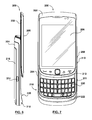
- Figure 2 is a first side view of a portable electronic device according to one embodiment shown in a closed position
- Figure 5 is a back view of the portable electronic device of Figure 2 ;
- Figure 9 is a back view of the portable electronic device of Figure 6 ;
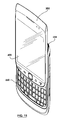
- Figure 10 is a perspective view of the portable electronic device of Figure 2 shown in the closed position
- Figure 12 is a rear view of the portable electronic device of Figure 10 with a battery cover and a rear cover removed;
- Figure 13 is a front view of the rear cover
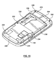
- Figure 15 is a rear view of the portable electronic device of Figure 12 with the rear cover attached;
- Figure 16 is a front view of the portable electronic device of Figure 2 with a front bezel partially positioned on the portable electronic device;
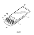
- Figure 17 is a front view of the portable electronic device of Figure 16 with the front bezel fully positioned on the portable electronic device;
- Figure 18 is a rear view of the portable electronic device of Figure 17 .
- the following describes an electronic device that includes a housing, a touch-sensitive display exposed by a front of the housing, and functional components comprising memory and a processor coupled to the memory and the touch-sensitive display.
- Figure 1 shows a simplified block diagram of components including internal components of a portable electronic device according to one embodiment.
- the portable electronic device 100 includes multiple components such as a processor 102 that controls the operations of the portable electronic device 100. Communication functions, including data communications, voice communications, or both may be performed through a communication subsystem 104. Data received by the portable electronic device 100 may be decompressed and decrypted by a decoder 106. The communication subsystem 104 may receive messages from and send messages to a wireless network 150.
- the wireless network 150 may be any type of wireless network, including, but not limited to, data-centric wireless networks, voice-centric wireless networks, and dual-mode networks that support both voice and data communications over the same base stations.
- the portable electronic device 100 may be a battery-powered device and as shown includes a battery interface 142 for receiving one or more rechargeable batteries 144.
- the processor 102 also interacts with additional subsystems such as a Random Access Memory (RAM) 108, a flash memory 110, a display 112 with a touch-sensitive overlay 114 connected to an electronic controller 116 that together comprise a touch-sensitive display 118, an actuator assembly 120, one or more optional force sensors 122, an auxiliary input/output (I/O) subsystem 124, a data port 126, a speaker 128, a microphone 130, short-range communications 132 and other device subsystems 134.
- RAM Random Access Memory
- flash memory 110 a flash memory 110
- display 112 with a touch-sensitive overlay 114 connected to an electronic controller 116 that together comprise a touch-sensitive display 118, an actuator assembly 120, one or more optional force sensors 122, an auxiliary input/output (I/O) subsystem 124, a data port 126, a speaker 128, a microphone 130, short-range communications 132 and other device subsystems 134.
- I/O auxiliary input/output
- User-interaction with the graphical user interface may be performed through the touch-sensitive overlay 114.
- the processor 102 may interact with the touch-sensitive overlay 114 via the electronic controller 116.
- Information such as text, characters, symbols, images, icons, and other items that may be displayed or rendered on a portable electronic device, may be displayed on the touch-sensitive display 118 via the processor 102.
- the portable electronic device 100 may use a Subscriber Identity Module or a Removable User Identity Module (SIM/RUIM) card 138 inserted into a SIM/RUIM interface 140 for communication with a network such as the wireless network 150.
- SIM/RUIM Removable User Identity Module
- user identification information may be programmed into the flash memory 110 or performed using other techniques.
- the portable electronic device 100 also includes an operating system 146 and software components 148 that may be executed by the processor 102 and which may be stored in a persistent store, such as the flash memory 110. Additional applications may be loaded onto the portable electronic device 100 through the wireless network 150, the auxiliary I/O subsystem 124, the data port 126, the short-range communications subsystem 132, or other suitable device subsystems 134.
- the overall operation of the portable electronic device 100 may be similar.
- the speaker 128 outputs audible information converted from electrical signals
- the microphone 130 converts audible information into electrical signals for processing.
- FIG. 2 illustrated generally therein is a portable electronic device 200 according to one embodiment.
- the portable electronic device 200 generally includes an upper housing 202 (or sliding portion) and a lower housing 204 (or base portion).
- the upper housing 202 and lower housing 204 are coupled together and are slidable between a closed position (as shown in Figure 2 ) and an open position (e.g. as shown in Figure 6 ).
- the upper housing 202 generally includes a display 206, which could be an LCD display and which may have touch screen capabilities.
- one or both of the upper housing 202 and lower housing 204 may include one or more input apparatus, such as navigation keys or buttons, a physical or virtual keyboard, a trackpad, trackball, multimedia keys, etc.
- input apparatus such as navigation keys or buttons, a physical or virtual keyboard, a trackpad, trackball, multimedia keys, etc.
- the upper housing 202 as shown includes an auxiliary input device 212.
- the auxiliary input device may be an optical navigation module (e.g. a trackpad) that responds to user interaction, and which may be used for navigating around the display screen 206, to select objects on the display screen, or for other purposes.
- the auxiliary input device 212 may be a mechanical device that responds to user interaction (e.g. a trackball).
- the display 206 and the auxiliary input device 212 are generally disposed on a front of the upper housing 202 and exposed for user accessibility when the portable electronic device 200 is in either of the open or closed positions.
- the upper housing 202 may also include other input devices, such as a dedicated phone application button, a dedicated "disconnect call” button, a home screen button, etc.
- these input devices may include optical sensors, mechanical buttons, or both.
- the lower housing 204 may include various buttons and other controls, such as buttons 208 and 210, and which could be used for navigation, to control volume or for other purposes.
- the lower housing 204 could also include one or more application buttons 211 that can be used to automatically launch a particular application on the portable electronic device (e.g. a camera application, a phone application, etc.).
- the button 211 may be configurable by a user (e.g. the user may be able to select the particular application launched by the button 211).
- the lower housing 204 could also include one or more input or output ports, (e.g. I/O ports), such as a microUSB port 214.
- I/O ports such as a microUSB port 214.
- the port 214 may be used for data communication with the portable electronic device 200, for charging of a battery (not shown) on the device 200 or for both.
- the keypad 220 is covered by the upper housing 202. This may be beneficial as it may protect the keypad 220 when not in use, and may also inhibit undesired keys from being pressed when the user is carrying the portable electronic device 200 (e.g. in a user's pocket). However, in some cases (e.g. when the display 206 is a touchsceen) the user may be able to perform functions on the portable electronic device 200 while the device 200 is closed by interacting with the display screen 206 (e.g. using buttons 208, 210, 211, the auxiliary input device 212, the display screen 206 itself, etc.).
- the keypad 220 is exposed for user accessibility.
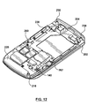
- FIG 12 illustrates a rear perspective view of the lower housing 204 of the portable electronic device 200 with the battery cover 216 and a rear cover 226 (see Figure 13 ) removed.
- the lower housing 204 of the portable electronic device 200 (with the battery cover 216 and the rear cover 226 removed) will be referred to herein as the main portion of the lower housing 204 or simply the lower housing 204.
- the main portion of the lower housing 204 includes an antenna 228 (which may be part of the communications subsystem 104), which may be used for sending and receiving voice communications, or data communications, or both.
- the antenna 228 is provided in the lower portion 218 of the lower housing 204. In some embodiments the antenna 228 may be tucked behind and abut an inner surface of the lower housing 204.
- the main portion of the lower housing 204 may also include a printed circuit board (PCB) 230.
- the PCB 230 may include various electronic components as will be understood by a person skilled in the art, including for example a processor (which could be processor 102), a memory (which could be RAM 108 or flash memory 110), and the SIM/RUIM interface 140, which may be used for receiving a SIM/RUIM card and for communication with the wireless network 150.
- FIG 13 illustrates a front perspective view of the rear cover 226.
- the rear cover 226 includes three cut-outs 232, 234, and 236 (generally being defined as open regions in the material of the cover 226 and which may be formed as openings when the cover 226 is manufactured).
- cut-outs 232, 234, and 236 allow for easy access to the battery opening 238, the SIM/RUIM interface 140, and the antenna 228 when the battery cover 216 of the device 200 is removed.
- FIG 15 is a rear perspective view of the lower housing 204 with the rear cover 226 attached, and the battery cover 216 removed.
- the rear cover 226 is attached to the lower housing 204 via the fasteners (i.e. screws) 248, 250, 252 and 254, the cut-outs 232, 234, and 236 in the rear cover 226 leave the battery opening 238, the SIM/RUIM interface 140, and the antenna 228 exposed. This tends to allow easy access to the battery opening 238, the SIM/RUIM interface 140 and the antenna 228 when the battery cover 216 is removed.
- the first solution i.e. installing the two top fasteners on the front face of the portable electronic device
- the portable electronic device has a slidable upper housing (i.e. upper housing 202) movable relative to a lower housing (i.e., lower housing 204) between an open position and a closed position.
- the rear cover i.e. rear cover 2266
- the upper housing i.e. upper housing 202
- the front face of the lower housing may already be in position making it difficult to install top fasteners on the front face of the lower housing.
- the second solution using an additional cosmetic piece to cover the fasteners, may also be less than ideal. Specifically, this solution adds an additional component that increases the complexity and cost of the portable electronic device. Furthermore, the addition of a cosmetic piece to cover the top fasteners may disrupt a seamless design intent that industrial design desires. For example, an additional cosmetic piece may add visible seams to the design that may not be desired.
- Figure 16 is a front perspective view of the portable electronic device 200 in the open position, with the front bezel 264 partially positioned on the portable electronic device 200.
- Figure 16 is used to demonstrate how the front bezel 264 is attached to the lower housing 204.
- the front bezel 264 includes a front portion 266, a rear portion 268 and two side portions 270 and 272 that together generally form a closed loop or "ring" shaped member.
- the front portion 266 covers a lower portion 274 of the front face of the lower housing 204
- the two side portions 270 and 272 lie along (and cover) the sides of the lower housing 204
- the rear portion 268 covers an upper portion 276 (See Figures 14 and 15 ) of the lower housing 204/rear cover 226.
- the upper portion 276 of the rear cover 226 includes the two top fasteners 248 and 250.
- the front bezel 264 performs two benefits: (i) it acts as a clamp by holding the lower housing 204 and the rear cover 226 in position (generally securing them together); and (ii) it performs a cosmetic function by covering the two upper fasteners 248 and 250.
- Figure 18 is a rear view of the portable electronic device 200 in the closed position, with the front bezel 264 fully positioned on the portable electronic device 200 and the battery cover 216 removed. It can be seen in Figure 18 , that when the front bezel 264 is fully positioned on the portable electronic device 200, the rear portion 268 of the front bezel 264 completely covers the upper portion 276 of the rear cover 226 including the two top fasteners 248 and 250.
- the front bezel 264 may be attached to the lower housing 204 via one or more bezel fasteners 278 and 280 (i.e. screws).
- Figure 18 shoes the front bezel 264 being attached to the lower housing 204 using two screws, it will be evident to a person of skill in the art that other types and numbers of fasteners may be used.
- the two fasteners 278 and 280 may be inserted into two small apertures 282 and 284 in the rear cover 226, pass through two small apertures 286 and 288 in the lower housing 204 and be received in two small apertures (not shown) in the front bezel 264.
Landscapes
- Engineering & Computer Science (AREA)
- Signal Processing (AREA)
- Telephone Set Structure (AREA)
- Casings For Electric Apparatus (AREA)
Abstract
Description
- This application claims the benefit of
U.S. Provisional Patent Application Serial No. 61/304,709 filed February 15, 2010 - Embodiments herein relate to portable electronic devices, and in particular to portable electronic devices having a slidable upper housing and lower housing movable between an open position and a closed position, and including a front bezel for holding the components of the portable electronic device together.
- Electronic devices, including portable electronic devices, have gained widespread use and may provide a variety of functions including, for example, telephonic, electronic text messaging and other personal information manager (PIM) application functions. Portable electronic devices can include several types of devices including mobile stations such as simple cellular phones, smart phones, Personal Digital Assistants (PDAs), tablets and laptop computers.
- Devices such as PDAs or smart phones are generally intended for handheld use and ease of portability. Smaller devices are generally desirable for portability. Touch-sensitive devices constructed of a display, such as a liquid crystal display (LCD), with a touch-sensitive overlay may be useful on handheld devices as such handheld devices are small and are therefore limited in space available for user input and output devices. Further, the screen content on the touch-sensitive devices can be modified depending on the functions and operations being performed.
- Embodiments of the present disclosure will now be described, by way of example only, with reference to the attached Figures, wherein:
-
Figure 1 is a simplified block diagram of components including internal components of a portable electronic device according to one embodiment; -
Figure 2 is a first side view of a portable electronic device according to one embodiment shown in a closed position; -
Figure 3 is a front view of the portable electronic device ofFigure 2 ; -
Figure 4 is a second side view of the portable electronic device ofFigure 2 ; -
Figure 5 is a back view of the portable electronic device ofFigure 2 ; -
Figure 6 is a first side view of the portable electronic device ofFigure 2 shown in an open position; -
Figure 7 is a front view of the portable electronic device ofFigure 6 ; -
Figure 8 is a second side view of the portable electronic device ofFigure 6 ; -
Figure 9 is a back view of the portable electronic device ofFigure 6 ; -
Figure 10 is a perspective view of the portable electronic device ofFigure 2 shown in the closed position; -
Figure 11 is a perspective view of the portable electronic device ofFigure 6 shown in the open position; -
Figure 12 is a rear view of the portable electronic device ofFigure 10 with a battery cover and a rear cover removed; -
Figure 13 is a front view of the rear cover; -
Figure 14 is a rear view of the portable electronic device ofFigure 12 and a rear view of the rear cover ofFigure 13 ; -
Figure 15 is a rear view of the portable electronic device ofFigure 12 with the rear cover attached; -
Figure 16 is a front view of the portable electronic device ofFigure 2 with a front bezel partially positioned on the portable electronic device; -
Figure 17 is a front view of the portable electronic device ofFigure 16 with the front bezel fully positioned on the portable electronic device; and -
Figure 18 is a rear view of the portable electronic device ofFigure 17 . - The following describes an electronic device that includes a housing, a touch-sensitive display exposed by a front of the housing, and functional components comprising memory and a processor coupled to the memory and the touch-sensitive display.
- It will be appreciated that for simplicity and clarity of illustration, where considered appropriate, reference numerals may be repeated among the figures to indicate corresponding or analogous elements. In addition, numerous specific details are set forth in order to provide a thorough understanding of the example embodiments described herein. However, it will be understood by those of ordinary skill in the art that the example embodiments described herein may be practiced without these specific details. In other instances, well-known methods, procedures and components have not been described in detail so as not to obscure the example embodiments described herein. Also, the description is not to be considered as limited to the scope of the example embodiments described herein.
-
Figure 1 shows a simplified block diagram of components including internal components of a portable electronic device according to one embodiment. - The portable
electronic device 100 includes multiple components such as aprocessor 102 that controls the operations of the portableelectronic device 100. Communication functions, including data communications, voice communications, or both may be performed through acommunication subsystem 104. Data received by the portableelectronic device 100 may be decompressed and decrypted by adecoder 106. Thecommunication subsystem 104 may receive messages from and send messages to awireless network 150. - The
wireless network 150 may be any type of wireless network, including, but not limited to, data-centric wireless networks, voice-centric wireless networks, and dual-mode networks that support both voice and data communications over the same base stations. - The portable
electronic device 100 may be a battery-powered device and as shown includes abattery interface 142 for receiving one or morerechargeable batteries 144. - The
processor 102 also interacts with additional subsystems such as a Random Access Memory (RAM) 108, aflash memory 110, adisplay 112 with a touch-sensitive overlay 114 connected to anelectronic controller 116 that together comprise a touch-sensitive display 118, anactuator assembly 120, one or moreoptional force sensors 122, an auxiliary input/output (I/O)subsystem 124, adata port 126, aspeaker 128, amicrophone 130, short-range communications 132 andother device subsystems 134. - User-interaction with the graphical user interface may be performed through the touch-
sensitive overlay 114. Theprocessor 102 may interact with the touch-sensitive overlay 114 via theelectronic controller 116. Information, such as text, characters, symbols, images, icons, and other items that may be displayed or rendered on a portable electronic device, may be displayed on the touch-sensitive display 118 via theprocessor 102. - The
processor 102 may also interact with anaccelerometer 136 as shown inFigure 1 . Theaccelerometer 136 may include a cantilever beam with a proof mass and suitable deflection sensing circuitry. Theaccelerometer 136 may be utilized for detecting direction of gravitational forces or gravity-induced reaction forces. - To identify a subscriber for network access according to the present embodiment, the portable
electronic device 100 may use a Subscriber Identity Module or a Removable User Identity Module (SIM/RUIM)card 138 inserted into a SIM/RUIM interface 140 for communication with a network such as thewireless network 150. Alternatively, user identification information may be programmed into theflash memory 110 or performed using other techniques. - The portable
electronic device 100 also includes anoperating system 146 andsoftware components 148 that may be executed by theprocessor 102 and which may be stored in a persistent store, such as theflash memory 110. Additional applications may be loaded onto the portableelectronic device 100 through thewireless network 150, the auxiliary I/O subsystem 124, thedata port 126, the short-range communications subsystem 132, or othersuitable device subsystems 134. - In use, a received signal such as a text message, an e-mail message, or web page download may be processed by the
communication subsystem 104 and input to theprocessor 102. Theprocessor 102 may then process the received signal for output to thedisplay 112 or alternatively to the auxiliary I/O subsystem 124. A subscriber may also compose data items, such as e-mail messages, for example, which may be transmitted over thewireless network 150 through thecommunication subsystem 104. - For voice communications, the overall operation of the portable
electronic device 100 may be similar. Thespeaker 128 outputs audible information converted from electrical signals, and themicrophone 130 converts audible information into electrical signals for processing. - Turning now to
Figures 2 to 10 , illustrated generally therein is a portableelectronic device 200 according to one embodiment. - The portable
electronic device 200 generally includes an upper housing 202 (or sliding portion) and a lower housing 204 (or base portion). Theupper housing 202 andlower housing 204 are coupled together and are slidable between a closed position (as shown inFigure 2 ) and an open position (e.g. as shown inFigure 6 ). - As shown, the
upper housing 202 generally includes adisplay 206, which could be an LCD display and which may have touch screen capabilities. - As shown, one or both of the
upper housing 202 andlower housing 204 may include one or more input apparatus, such as navigation keys or buttons, a physical or virtual keyboard, a trackpad, trackball, multimedia keys, etc. - For example, the
upper housing 202 as shown includes anauxiliary input device 212. As shown, the auxiliary input device may be an optical navigation module (e.g. a trackpad) that responds to user interaction, and which may be used for navigating around thedisplay screen 206, to select objects on the display screen, or for other purposes. In some other embodiments, theauxiliary input device 212 may be a mechanical device that responds to user interaction (e.g. a trackball). - The
display 206 and theauxiliary input device 212 are generally disposed on a front of theupper housing 202 and exposed for user accessibility when the portableelectronic device 200 is in either of the open or closed positions. - The
upper housing 202 may also include other input devices, such as a dedicated phone application button, a dedicated "disconnect call" button, a home screen button, etc. In various embodiments, these input devices may include optical sensors, mechanical buttons, or both. - Turning now to the
lower housing 204, thelower housing 204 may include various buttons and other controls, such asbuttons - The
lower housing 204 could also include one ormore application buttons 211 that can be used to automatically launch a particular application on the portable electronic device (e.g. a camera application, a phone application, etc.). In some embodiments, thebutton 211 may be configurable by a user (e.g. the user may be able to select the particular application launched by the button 211). - As shown in
Figures 2 and6 , thelower housing 204 could also include one or more input or output ports, (e.g. I/O ports), such as amicroUSB port 214. In some examples, theport 214 may be used for data communication with the portableelectronic device 200, for charging of a battery (not shown) on thedevice 200 or for both. - As shown, the
lower housing 204 may also include abattery cover 216 for covering the battery (not shown). In some embodiments, thebattery cover 216 may be removable. In other embodiments, thebattery cover 216 may be permanently fixed to the device. - In some embodiments, the
lower housing 204 may also include anaudio jack 217. Theaudio jack 217 may be used to couple the portableelectronic device 200 to a speaker, a microphone, or both, for example for use in voice communication. - Turning now to
Figures 6 to 9 , as shown when the portableelectronic device 200 is in the open position, akeypad 220 is exposed on alower portion 218 of thelower housing 204. Thekeypad 220 generally includes a plurality ofalphanumeric keys 222, which may be positioned in a plurality of rows and columns. In some embodiments, thekeys 222 may represent the alphabet and may be arranged with a standard keyboard layout (e.g. QWERTY, QWERTZ, DVORAK, etc.) - As shown in
Figures 2 to 5 , when the portableelectronic device 200 is in the closed position, thekeypad 220 is covered by theupper housing 202. This may be beneficial as it may protect thekeypad 220 when not in use, and may also inhibit undesired keys from being pressed when the user is carrying the portable electronic device 200 (e.g. in a user's pocket). However, in some cases (e.g. when thedisplay 206 is a touchsceen) the user may be able to perform functions on the portableelectronic device 200 while thedevice 200 is closed by interacting with the display screen 206 (e.g. using buttons auxiliary input device 212, thedisplay screen 206 itself, etc.). - When the portable
electronic device 200 is in the open position (as shown inFigures 6 to 9 ), thekeypad 220 is exposed for user accessibility. - In some embodiments, the
display 206 may be a touch-sensitive display. The touch-sensitive display may be a capacitive touch-sensitive display, for example, and a user's touch on the touch-sensitive display may be determined by determining an X and Y location of the touch, with the X location determined by a signal generated as a result of capacitive coupling with a touch sensor layer and the Y location determined by the signal generated as a result of capacitive coupling with another touch sensor layer. Each of the touch-sensor layers provides a signal to a controller that represents the respective X and Y touch location values. Thus a feature such as a virtual button or other feature displayed on the touch-sensitive display may be selected by a mapping of the touch location to a feature on the touch-sensitive display. - In some embodiments, the portable
electronic device 200 is generally taller than it is wide. In such embodiments, as the portableelectronic device 200 moves between the open position and the closed position, theupper housing 202 andlower housing 204 move along a longitudinal axis of the portableelectronic device 200. - Reference is now made to
Figure 12 , which illustrates a rear perspective view of thelower housing 204 of the portableelectronic device 200 with thebattery cover 216 and a rear cover 226 (seeFigure 13 ) removed. Thelower housing 204 of the portable electronic device 200 (with thebattery cover 216 and therear cover 226 removed) will be referred to herein as the main portion of thelower housing 204 or simply thelower housing 204. - As can be seen in
Figure 12 , the main portion of thelower housing 204 includes an antenna 228 (which may be part of the communications subsystem 104), which may be used for sending and receiving voice communications, or data communications, or both. As shown, theantenna 228 is provided in thelower portion 218 of thelower housing 204. In some embodiments theantenna 228 may be tucked behind and abut an inner surface of thelower housing 204. - The main portion of the
lower housing 204 may also include a printed circuit board (PCB) 230. ThePCB 230 may include various electronic components as will be understood by a person skilled in the art, including for example a processor (which could be processor 102), a memory (which could beRAM 108 or flash memory 110), and the SIM/RUIM interface 140, which may be used for receiving a SIM/RUIM card and for communication with thewireless network 150. - Reference is now made to
Figure 13 , which illustrates a front perspective view of therear cover 226. Therear cover 226 includes three cut-outs cover 226 and which may be formed as openings when thecover 226 is manufactured). - The first cut-out 232 works in conjunction with the
lower housing 204 to form a battery opening 238 (shown inFigure 15 ) for receiving a battery (e.g. battery 144), although the battery is not shown in the Figures. - The second cut-out 234 allows for exposure of the SIM/
RUIM interface 140 when therear cover 226 is mounted to thelower housing 204. - The third cut-out 236 allows for exposure of the
antenna 228 when therear cover 226 is mounted to thelower housing 204. - Generally, these cut-
outs battery opening 238, the SIM/RUIM interface 140, and theantenna 228 when thebattery cover 216 of thedevice 200 is removed. - Reference is now made to
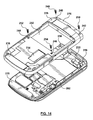
Figure 14 , which is an exploded rear perspective view of the main portion of thelower housing 204 and a rear perspective view of therear cover 226.Figure 14 is used to demonstrate how therear cover 226 may be attached to thelower housing 204. - In particular, as shown in
Figure 14 , therear cover 226 may have foursmall apertures apertures fastener fasteners - The
rear cover 226 may be placed over the rear portion of thelower housing 204 and the fasteners (i.e. screws) 248, 250, 252 and 254 received in correspondingapertures Figure 12 ) to attach therear cover 226 to thelower housing 204. - Reference is now made to
Figure 15 , which is a rear perspective view of thelower housing 204 with therear cover 226 attached, and thebattery cover 216 removed. As can be seen inFigure 15 , when therear cover 226 is attached to thelower housing 204 via the fasteners (i.e. screws) 248, 250, 252 and 254, the cut-outs rear cover 226 leave thebattery opening 238, the SIM/RUIM interface 140, and theantenna 228 exposed. This tends to allow easy access to thebattery opening 238, the SIM/RUIM interface 140 and theantenna 228 when thebattery cover 216 is removed. - It also can been seen in
Figure 15 , that when therear cover 226 is attached to thelower housing 204, at least a portion of each of thefasteners battery cover 216 is attached to the lower housing (not shown), the twolower fasteners top fasteners battery cover 216 is installed or attached to thelower housing 204. This is generally undesirable, as it can interfere with the aesthetic appearance of thedevice 200. Furthermore, it may allow thefasteners - To address this issue, in some embodiments, the portable
electronic device 200 includes a front bezel 264 (seeFigures 16 to 18 ) that secures therear cover 226 to thelower housing 204 and also covers the twotop fasteners fasteners 248 and 250) on the front face of the portable electronic device and then covering the fasteners with a cosmetic piece; or, (ii) using an additional cosmetic piece to cover the fasteners on the rear face. - However, the first solution (i.e. installing the two top fasteners on the front face of the portable electronic device) may not be feasible when the portable electronic device has a slidable upper housing (i.e. upper housing 202) movable relative to a lower housing (i.e., lower housing 204) between an open position and a closed position. Specifically, when the rear cover (i.e. rear cover 226) is assembled or attached to the lower housing (i.e. lower housing 204), the upper housing (i.e. upper housing 202) may already be in position making it difficult to install top fasteners on the front face of the lower housing.
- The second solution, using an additional cosmetic piece to cover the fasteners, may also be less than ideal. Specifically, this solution adds an additional component that increases the complexity and cost of the portable electronic device. Furthermore, the addition of a cosmetic piece to cover the top fasteners may disrupt a seamless design intent that industrial design desires. For example, an additional cosmetic piece may add visible seams to the design that may not be desired.
- Reference is now made to
Figure 16 , which is a front perspective view of the portableelectronic device 200 in the open position, with thefront bezel 264 partially positioned on the portableelectronic device 200.Figure 16 is used to demonstrate how thefront bezel 264 is attached to thelower housing 204. - As shown, the
front bezel 264 includes afront portion 266, arear portion 268 and twoside portions front bezel 264 is positioned on the portableelectronic device 200, thefront portion 266 covers alower portion 274 of the front face of thelower housing 204, the twoside portions lower housing 204, and therear portion 268 covers an upper portion 276 (SeeFigures 14 and15 ) of thelower housing 204/rear cover 226. Theupper portion 276 of therear cover 226 includes the twotop fasteners front bezel 264 performs two benefits: (i) it acts as a clamp by holding thelower housing 204 and therear cover 226 in position (generally securing them together); and (ii) it performs a cosmetic function by covering the twoupper fasteners - In one embodiment, the
front bezel 264 is made of a non-conductive vacuum metallization (NCVM) material. As is known to persons of skill in the art, the NCVM process deposits a thin nonconductive metal on a resin surface, such as plastic. One of the benefits of NCVM material is that the thin nonconductive metal does not interfere with radio frequency transmissions. Accordingly, a NCVM material allows thefront bezel 264 to look like metal without having the adverse affects an actual metal might have. Specifically, when made of NCVM material, thefront bezel 264 does not affect the radio frequency (RF) transmissions of theantenna 228 in the same manner that a metal bezel would. This may be particularly important due to the proximity of thefront bezel 264 to theantenna 228. - Reference is now made to
Figure 17 , which is a front perspective view of the portableelectronic device 200 in the open position, with thefront bezel 264 fully positioned on the portableelectronic device 200. - Reference is now made to
Figure 18 , which is a rear view of the portableelectronic device 200 in the closed position, with thefront bezel 264 fully positioned on the portableelectronic device 200 and thebattery cover 216 removed. It can be seen inFigure 18 , that when thefront bezel 264 is fully positioned on the portableelectronic device 200, therear portion 268 of thefront bezel 264 completely covers theupper portion 276 of therear cover 226 including the twotop fasteners - Once the
front bezel 264 is fully positioned on the portableelectronic device 200, thefront bezel 264 may be attached to thelower housing 204 via one ormore bezel fasteners 278 and 280 (i.e. screws). AlthoughFigure 18 shoes thefront bezel 264 being attached to thelower housing 204 using two screws, it will be evident to a person of skill in the art that other types and numbers of fasteners may be used. - The two
fasteners small apertures rear cover 226, pass through twosmall apertures lower housing 204 and be received in two small apertures (not shown) in thefront bezel 264. - While the above description provides examples of one or more processes or apparatuses, it will be appreciated that other processes or apparatuses may be within the scope of the accompanying claims.
Claims (8)
- A portable electronic device (200), comprising:a lower housing (204) comprising a main portion and a rear cover (226), the rear cover being attached to the main portion by at least one fastener (248, 250);an upper housing (202) coupled to the lower housing (204) and slideable relative thereto between a closed position and an open position; anda bezel (264) extending around the lower housing (204) for holding the main portion and the rear cover (226) together, and for providing cosmetic coverage to the at least one fastener (248, 250).
- The portable electronic device (200) of claim 1, wherein:the bezel (264) comprises a front portion (266), a rear portion (268) andtwo side portions (270, 272); andthe front portion (266) of the bezel (264) covers a lower portion (274) of a front face of the main portion.
- The portable electronic device (200) of claim 2, wherein the rear portion (268) of the bezel (264) covers an upper portion (276) of a rear face of the rear cover (226).
- The portable electronic device (200) of claim 3, wherein the at least one fastener (248, 250) is positioned on the upper portion of the rear face of the rear cover (226) so that the rear portion (268) of the bezel (264) provides cosmetic coverage to the at least one fastener (248, 250).
- The portable electronic device (200) of any one of claims 2 to 4, wherein the front portion (266), the rear portion (268) and the two side portions (270, 272) form a ring.
- The portable electronic device (200) of any preceding claim, wherein the at least one fastener (248, 250) is a screw.
- The portable electronic device (200) of any preceding claim, wherein the bezel (264) is attached to the lower housing (204) by at least one bezel fastener (278, 280).
- The portable electronic device (200) of any preceding claim, wherein the bezel (264) is made of a non-conductive vacuum metallization material so as to inhibit radio frequency interference of the portable electronic device (200).
Applications Claiming Priority (1)
| Application Number | Priority Date | Filing Date | Title |
|---|---|---|---|
| US30470910P | 2010-02-15 | 2010-02-15 |
Publications (2)
| Publication Number | Publication Date |
|---|---|
| EP2367338A1 true EP2367338A1 (en) | 2011-09-21 |
| EP2367338B1 EP2367338B1 (en) | 2014-03-26 |
Family
ID=44010131
Family Applications (1)
| Application Number | Title | Priority Date | Filing Date |
|---|---|---|---|
| EP11154320.3A Not-in-force EP2367338B1 (en) | 2010-02-15 | 2011-02-14 | Electronic device including a front bezel operable to keep the device together |
Country Status (3)
| Country | Link |
|---|---|
| US (1) | US8638556B2 (en) |
| EP (1) | EP2367338B1 (en) |
| CA (1) | CA2731606C (en) |
Families Citing this family (2)
| Publication number | Priority date | Publication date | Assignee | Title |
|---|---|---|---|---|
| KR102376981B1 (en) * | 2015-04-22 | 2022-03-21 | 삼성전자주식회사 | Electronic device having heat transffering structure |
| JP6781390B1 (en) * | 2019-09-25 | 2020-11-04 | 富士通クライアントコンピューティング株式会社 | Electronics |
Citations (2)
| Publication number | Priority date | Publication date | Assignee | Title |
|---|---|---|---|---|
| US20080031612A1 (en) * | 2006-08-04 | 2008-02-07 | Hon Hai Precision Industry Co., Ltd. | Mobile communication device |
| US20090257207A1 (en) * | 2008-04-11 | 2009-10-15 | Wang Erik L | Portable electronic device with two-piece housing |
Family Cites Families (8)
| Publication number | Priority date | Publication date | Assignee | Title |
|---|---|---|---|---|
| US5422751A (en) * | 1992-10-14 | 1995-06-06 | Apple Computer, Inc. | Liquid crystal display assembly employing front bezel, frame holding liquid crystal cell attached to bezel, and light source and back plate attached to bezel |
| US5848152A (en) | 1995-09-26 | 1998-12-08 | Motorola, Inc. | Communication device having interchangeable faceplates and active keypad cover |
| US6177881B1 (en) * | 1998-03-12 | 2001-01-23 | Motorola, Inc. | Vibrator mounting assembly for a portable communication device |
| KR100605862B1 (en) | 2002-07-02 | 2006-07-31 | 삼성전자주식회사 | Sliding type wireless terminal |
| US20060176654A1 (en) * | 2005-01-18 | 2006-08-10 | Amphenol-T&M Antennas | Sliding assembly for portable handset |
| EP1796351B1 (en) | 2005-12-12 | 2016-10-19 | LG Electronics Inc. | Sliding type mobile communication terminal |
| KR100800662B1 (en) | 2006-10-02 | 2008-02-01 | 삼성전자주식회사 | Battery cover device of portable terminal |
| KR20100053222A (en) * | 2008-11-12 | 2010-05-20 | 삼성전자주식회사 | Slide type portable terminal |
-
2011
- 2011-02-14 EP EP11154320.3A patent/EP2367338B1/en not_active Not-in-force
- 2011-02-14 US US13/027,086 patent/US8638556B2/en not_active Expired - Fee Related
- 2011-02-14 CA CA2731606A patent/CA2731606C/en not_active Expired - Fee Related
Patent Citations (2)
| Publication number | Priority date | Publication date | Assignee | Title |
|---|---|---|---|---|
| US20080031612A1 (en) * | 2006-08-04 | 2008-02-07 | Hon Hai Precision Industry Co., Ltd. | Mobile communication device |
| US20090257207A1 (en) * | 2008-04-11 | 2009-10-15 | Wang Erik L | Portable electronic device with two-piece housing |
Also Published As
| Publication number | Publication date |
|---|---|
| EP2367338B1 (en) | 2014-03-26 |
| US8638556B2 (en) | 2014-01-28 |
| US20120039029A1 (en) | 2012-02-16 |
| CA2731606C (en) | 2014-06-17 |
| CA2731606A1 (en) | 2011-08-15 |
Similar Documents
| Publication | Publication Date | Title |
|---|---|---|
| CA2732297C (en) | Portable electronic device having holster and including a plurality of position sensors | |
| US20120170177A1 (en) | Electronic device having an electronic compass adapted to detect when the device is in a holster | |
| EP2561671B1 (en) | Slidable mobile phone deactivates the touch screen while sliding the housings | |
| EP2474878B1 (en) | Electronic device having an electronic compass adapted to detect when the device is in a holster | |
| US8965465B2 (en) | Portable electronic device having at least one of resonator and shield | |
| CA2731606C (en) | Electronic device including a front bezel operable to secure the device together | |
| EP2445177B1 (en) | Mobile terminal having a slide module | |
| US8862190B2 (en) | Portable electronic device with upper housing and cover plate therefor | |
| CA2788765C (en) | Portable slidable electronic device having a dynamic flex alignment scheme and methods of assembling same | |
| CA2692875A1 (en) | Electronic device including breakthrough antenna | |
| US9020570B2 (en) | Portable electronic device with auxiliary input device and flex connector therefor | |
| CA2731763C (en) | Portable electronic device with upper housing and cover plate therefor |
Legal Events
| Date | Code | Title | Description |
|---|---|---|---|
| PUAI | Public reference made under article 153(3) epc to a published international application that has entered the european phase |
Free format text: ORIGINAL CODE: 0009012 |
|
| 17P | Request for examination filed |
Effective date: 20110216 |
|
| AK | Designated contracting states |
Kind code of ref document: A1 Designated state(s): AL AT BE BG CH CY CZ DE DK EE ES FI FR GB GR HR HU IE IS IT LI LT LU LV MC MK MT NL NO PL PT RO RS SE SI SK SM TR |
|
| AX | Request for extension of the european patent |
Extension state: BA ME |
|
| 17Q | First examination report despatched |
Effective date: 20120124 |
|
| RAP1 | Party data changed (applicant data changed or rights of an application transferred) |
Owner name: BLACKBERRY LIMITED |
|
| GRAP | Despatch of communication of intention to grant a patent |
Free format text: ORIGINAL CODE: EPIDOSNIGR1 |
|
| INTG | Intention to grant announced |
Effective date: 20130909 |
|
| RAP1 | Party data changed (applicant data changed or rights of an application transferred) |
Owner name: BLACKBERRY LIMITED |
|
| GRAS | Grant fee paid |
Free format text: ORIGINAL CODE: EPIDOSNIGR3 |
|
| GRAA | (expected) grant |
Free format text: ORIGINAL CODE: 0009210 |
|
| AK | Designated contracting states |
Kind code of ref document: B1 Designated state(s): AL AT BE BG CH CY CZ DE DK EE ES FI FR GB GR HR HU IE IS IT LI LT LU LV MC MK MT NL NO PL PT RO RS SE SI SK SM TR |
|
| REG | Reference to a national code |
Ref country code: GB Ref legal event code: FG4D |
|
| REG | Reference to a national code |
Ref country code: CH Ref legal event code: EP |
|
| REG | Reference to a national code |
Ref country code: AT Ref legal event code: REF Ref document number: 659475 Country of ref document: AT Kind code of ref document: T Effective date: 20140415 |
|
| REG | Reference to a national code |
Ref country code: IE Ref legal event code: FG4D |
|
| REG | Reference to a national code |
Ref country code: DE Ref legal event code: R096 Ref document number: 602011005685 Country of ref document: DE Effective date: 20140508 |
|
| REG | Reference to a national code |
Ref country code: NL Ref legal event code: T3 |
|
| PG25 | Lapsed in a contracting state [announced via postgrant information from national office to epo] |
Ref country code: LT Free format text: LAPSE BECAUSE OF FAILURE TO SUBMIT A TRANSLATION OF THE DESCRIPTION OR TO PAY THE FEE WITHIN THE PRESCRIBED TIME-LIMIT Effective date: 20140326 Ref country code: NO Free format text: LAPSE BECAUSE OF FAILURE TO SUBMIT A TRANSLATION OF THE DESCRIPTION OR TO PAY THE FEE WITHIN THE PRESCRIBED TIME-LIMIT Effective date: 20140626 |
|
| REG | Reference to a national code |
Ref country code: AT Ref legal event code: MK05 Ref document number: 659475 Country of ref document: AT Kind code of ref document: T Effective date: 20140326 |
|
| REG | Reference to a national code |
Ref country code: LT Ref legal event code: MG4D |
|
| PG25 | Lapsed in a contracting state [announced via postgrant information from national office to epo] |
Ref country code: SE Free format text: LAPSE BECAUSE OF FAILURE TO SUBMIT A TRANSLATION OF THE DESCRIPTION OR TO PAY THE FEE WITHIN THE PRESCRIBED TIME-LIMIT Effective date: 20140326 Ref country code: FI Free format text: LAPSE BECAUSE OF FAILURE TO SUBMIT A TRANSLATION OF THE DESCRIPTION OR TO PAY THE FEE WITHIN THE PRESCRIBED TIME-LIMIT Effective date: 20140326 |
|
| PG25 | Lapsed in a contracting state [announced via postgrant information from national office to epo] |
Ref country code: LV Free format text: LAPSE BECAUSE OF FAILURE TO SUBMIT A TRANSLATION OF THE DESCRIPTION OR TO PAY THE FEE WITHIN THE PRESCRIBED TIME-LIMIT Effective date: 20140326 Ref country code: RS Free format text: LAPSE BECAUSE OF FAILURE TO SUBMIT A TRANSLATION OF THE DESCRIPTION OR TO PAY THE FEE WITHIN THE PRESCRIBED TIME-LIMIT Effective date: 20140326 Ref country code: HR Free format text: LAPSE BECAUSE OF FAILURE TO SUBMIT A TRANSLATION OF THE DESCRIPTION OR TO PAY THE FEE WITHIN THE PRESCRIBED TIME-LIMIT Effective date: 20140326 |
|
| PG25 | Lapsed in a contracting state [announced via postgrant information from national office to epo] |
Ref country code: CY Free format text: LAPSE BECAUSE OF FAILURE TO SUBMIT A TRANSLATION OF THE DESCRIPTION OR TO PAY THE FEE WITHIN THE PRESCRIBED TIME-LIMIT Effective date: 20140326 Ref country code: CZ Free format text: LAPSE BECAUSE OF FAILURE TO SUBMIT A TRANSLATION OF THE DESCRIPTION OR TO PAY THE FEE WITHIN THE PRESCRIBED TIME-LIMIT Effective date: 20140326 Ref country code: EE Free format text: LAPSE BECAUSE OF FAILURE TO SUBMIT A TRANSLATION OF THE DESCRIPTION OR TO PAY THE FEE WITHIN THE PRESCRIBED TIME-LIMIT Effective date: 20140326 Ref country code: RO Free format text: LAPSE BECAUSE OF FAILURE TO SUBMIT A TRANSLATION OF THE DESCRIPTION OR TO PAY THE FEE WITHIN THE PRESCRIBED TIME-LIMIT Effective date: 20140326 Ref country code: IS Free format text: LAPSE BECAUSE OF FAILURE TO SUBMIT A TRANSLATION OF THE DESCRIPTION OR TO PAY THE FEE WITHIN THE PRESCRIBED TIME-LIMIT Effective date: 20140726 Ref country code: BE Free format text: LAPSE BECAUSE OF FAILURE TO SUBMIT A TRANSLATION OF THE DESCRIPTION OR TO PAY THE FEE WITHIN THE PRESCRIBED TIME-LIMIT Effective date: 20140326 Ref country code: BG Free format text: LAPSE BECAUSE OF FAILURE TO SUBMIT A TRANSLATION OF THE DESCRIPTION OR TO PAY THE FEE WITHIN THE PRESCRIBED TIME-LIMIT Effective date: 20140626 |
|
| PG25 | Lapsed in a contracting state [announced via postgrant information from national office to epo] |
Ref country code: SK Free format text: LAPSE BECAUSE OF FAILURE TO SUBMIT A TRANSLATION OF THE DESCRIPTION OR TO PAY THE FEE WITHIN THE PRESCRIBED TIME-LIMIT Effective date: 20140326 Ref country code: PL Free format text: LAPSE BECAUSE OF FAILURE TO SUBMIT A TRANSLATION OF THE DESCRIPTION OR TO PAY THE FEE WITHIN THE PRESCRIBED TIME-LIMIT Effective date: 20140326 Ref country code: AT Free format text: LAPSE BECAUSE OF FAILURE TO SUBMIT A TRANSLATION OF THE DESCRIPTION OR TO PAY THE FEE WITHIN THE PRESCRIBED TIME-LIMIT Effective date: 20140326 Ref country code: ES Free format text: LAPSE BECAUSE OF FAILURE TO SUBMIT A TRANSLATION OF THE DESCRIPTION OR TO PAY THE FEE WITHIN THE PRESCRIBED TIME-LIMIT Effective date: 20140326 |
|
| PG25 | Lapsed in a contracting state [announced via postgrant information from national office to epo] |
Ref country code: PT Free format text: LAPSE BECAUSE OF FAILURE TO SUBMIT A TRANSLATION OF THE DESCRIPTION OR TO PAY THE FEE WITHIN THE PRESCRIBED TIME-LIMIT Effective date: 20140728 |
|
| REG | Reference to a national code |
Ref country code: DE Ref legal event code: R097 Ref document number: 602011005685 Country of ref document: DE |
|
| PG25 | Lapsed in a contracting state [announced via postgrant information from national office to epo] |
Ref country code: DK Free format text: LAPSE BECAUSE OF FAILURE TO SUBMIT A TRANSLATION OF THE DESCRIPTION OR TO PAY THE FEE WITHIN THE PRESCRIBED TIME-LIMIT Effective date: 20140326 |
|
| PLBE | No opposition filed within time limit |
Free format text: ORIGINAL CODE: 0009261 |
|
| STAA | Information on the status of an ep patent application or granted ep patent |
Free format text: STATUS: NO OPPOSITION FILED WITHIN TIME LIMIT |
|
| 26N | No opposition filed |
Effective date: 20150106 |
|
| PG25 | Lapsed in a contracting state [announced via postgrant information from national office to epo] |
Ref country code: IT Free format text: LAPSE BECAUSE OF FAILURE TO SUBMIT A TRANSLATION OF THE DESCRIPTION OR TO PAY THE FEE WITHIN THE PRESCRIBED TIME-LIMIT Effective date: 20140326 |
|
| REG | Reference to a national code |
Ref country code: DE Ref legal event code: R097 Ref document number: 602011005685 Country of ref document: DE Effective date: 20150106 |
|
| PG25 | Lapsed in a contracting state [announced via postgrant information from national office to epo] |
Ref country code: SI Free format text: LAPSE BECAUSE OF FAILURE TO SUBMIT A TRANSLATION OF THE DESCRIPTION OR TO PAY THE FEE WITHIN THE PRESCRIBED TIME-LIMIT Effective date: 20140326 |
|
| PG25 | Lapsed in a contracting state [announced via postgrant information from national office to epo] |
Ref country code: LU Free format text: LAPSE BECAUSE OF FAILURE TO SUBMIT A TRANSLATION OF THE DESCRIPTION OR TO PAY THE FEE WITHIN THE PRESCRIBED TIME-LIMIT Effective date: 20150214 |
|
| REG | Reference to a national code |
Ref country code: CH Ref legal event code: PL |
|
| PG25 | Lapsed in a contracting state [announced via postgrant information from national office to epo] |
Ref country code: LI Free format text: LAPSE BECAUSE OF NON-PAYMENT OF DUE FEES Effective date: 20150228 Ref country code: CH Free format text: LAPSE BECAUSE OF NON-PAYMENT OF DUE FEES Effective date: 20150228 Ref country code: MC Free format text: LAPSE BECAUSE OF FAILURE TO SUBMIT A TRANSLATION OF THE DESCRIPTION OR TO PAY THE FEE WITHIN THE PRESCRIBED TIME-LIMIT Effective date: 20140326 |
|
| REG | Reference to a national code |
Ref country code: IE Ref legal event code: MM4A |
|
| PG25 | Lapsed in a contracting state [announced via postgrant information from national office to epo] |
Ref country code: IE Free format text: LAPSE BECAUSE OF NON-PAYMENT OF DUE FEES Effective date: 20150214 |
|
| REG | Reference to a national code |
Ref country code: FR Ref legal event code: PLFP Year of fee payment: 6 |
|
| PGFP | Annual fee paid to national office [announced via postgrant information from national office to epo] |
Ref country code: NL Payment date: 20160225 Year of fee payment: 6 Ref country code: DE Payment date: 20160226 Year of fee payment: 6 |
|
| PGFP | Annual fee paid to national office [announced via postgrant information from national office to epo] |
Ref country code: FR Payment date: 20160217 Year of fee payment: 6 Ref country code: GB Payment date: 20160226 Year of fee payment: 6 |
|
| PG25 | Lapsed in a contracting state [announced via postgrant information from national office to epo] |
Ref country code: GR Free format text: LAPSE BECAUSE OF FAILURE TO SUBMIT A TRANSLATION OF THE DESCRIPTION OR TO PAY THE FEE WITHIN THE PRESCRIBED TIME-LIMIT Effective date: 20140627 |
|
| PG25 | Lapsed in a contracting state [announced via postgrant information from national office to epo] |
Ref country code: MT Free format text: LAPSE BECAUSE OF FAILURE TO SUBMIT A TRANSLATION OF THE DESCRIPTION OR TO PAY THE FEE WITHIN THE PRESCRIBED TIME-LIMIT Effective date: 20140326 |
|
| PG25 | Lapsed in a contracting state [announced via postgrant information from national office to epo] |
Ref country code: SM Free format text: LAPSE BECAUSE OF FAILURE TO SUBMIT A TRANSLATION OF THE DESCRIPTION OR TO PAY THE FEE WITHIN THE PRESCRIBED TIME-LIMIT Effective date: 20140326 Ref country code: HU Free format text: LAPSE BECAUSE OF FAILURE TO SUBMIT A TRANSLATION OF THE DESCRIPTION OR TO PAY THE FEE WITHIN THE PRESCRIBED TIME-LIMIT; INVALID AB INITIO Effective date: 20110214 |
|
| PG25 | Lapsed in a contracting state [announced via postgrant information from national office to epo] |
Ref country code: TR Free format text: LAPSE BECAUSE OF FAILURE TO SUBMIT A TRANSLATION OF THE DESCRIPTION OR TO PAY THE FEE WITHIN THE PRESCRIBED TIME-LIMIT Effective date: 20140326 |
|
| REG | Reference to a national code |
Ref country code: DE Ref legal event code: R119 Ref document number: 602011005685 Country of ref document: DE |
|
| REG | Reference to a national code |
Ref country code: NL Ref legal event code: MM Effective date: 20170301 |
|
| GBPC | Gb: european patent ceased through non-payment of renewal fee |
Effective date: 20170214 |
|
| PG25 | Lapsed in a contracting state [announced via postgrant information from national office to epo] |
Ref country code: NL Free format text: LAPSE BECAUSE OF NON-PAYMENT OF DUE FEES Effective date: 20170301 |
|
| REG | Reference to a national code |
Ref country code: FR Ref legal event code: ST Effective date: 20171031 |
|
| PG25 | Lapsed in a contracting state [announced via postgrant information from national office to epo] |
Ref country code: DE Free format text: LAPSE BECAUSE OF NON-PAYMENT OF DUE FEES Effective date: 20170901 Ref country code: FR Free format text: LAPSE BECAUSE OF NON-PAYMENT OF DUE FEES Effective date: 20170228 |
|
| PG25 | Lapsed in a contracting state [announced via postgrant information from national office to epo] |
Ref country code: GB Free format text: LAPSE BECAUSE OF NON-PAYMENT OF DUE FEES Effective date: 20170214 |
|
| PG25 | Lapsed in a contracting state [announced via postgrant information from national office to epo] |
Ref country code: MK Free format text: LAPSE BECAUSE OF FAILURE TO SUBMIT A TRANSLATION OF THE DESCRIPTION OR TO PAY THE FEE WITHIN THE PRESCRIBED TIME-LIMIT Effective date: 20140326 |
|
| PG25 | Lapsed in a contracting state [announced via postgrant information from national office to epo] |
Ref country code: AL Free format text: LAPSE BECAUSE OF FAILURE TO SUBMIT A TRANSLATION OF THE DESCRIPTION OR TO PAY THE FEE WITHIN THE PRESCRIBED TIME-LIMIT Effective date: 20140326 |