EP2367054A1 - Turbulent air stream for cooling a liquid crystal panel - Google Patents
Turbulent air stream for cooling a liquid crystal panel Download PDFInfo
- Publication number
- EP2367054A1 EP2367054A1 EP11155390A EP11155390A EP2367054A1 EP 2367054 A1 EP2367054 A1 EP 2367054A1 EP 11155390 A EP11155390 A EP 11155390A EP 11155390 A EP11155390 A EP 11155390A EP 2367054 A1 EP2367054 A1 EP 2367054A1
- Authority
- EP
- European Patent Office
- Prior art keywords
- panels
- air
- wire
- polarizing
- liquid crystal
- Prior art date
- Legal status (The legal status is an assumption and is not a legal conclusion. Google has not performed a legal analysis and makes no representation as to the accuracy of the status listed.)
- Withdrawn
Links
Images




Classifications
-
- G—PHYSICS
- G03—PHOTOGRAPHY; CINEMATOGRAPHY; ANALOGOUS TECHNIQUES USING WAVES OTHER THAN OPTICAL WAVES; ELECTROGRAPHY; HOLOGRAPHY
- G03B—APPARATUS OR ARRANGEMENTS FOR TAKING PHOTOGRAPHS OR FOR PROJECTING OR VIEWING THEM; APPARATUS OR ARRANGEMENTS EMPLOYING ANALOGOUS TECHNIQUES USING WAVES OTHER THAN OPTICAL WAVES; ACCESSORIES THEREFOR
- G03B21/00—Projectors or projection-type viewers; Accessories therefor
- G03B21/14—Details
- G03B21/16—Cooling; Preventing overheating
-
- H—ELECTRICITY
- H04—ELECTRIC COMMUNICATION TECHNIQUE
- H04N—PICTORIAL COMMUNICATION, e.g. TELEVISION
- H04N9/00—Details of colour television systems
- H04N9/12—Picture reproducers
- H04N9/31—Projection devices for colour picture display, e.g. using electronic spatial light modulators [ESLM]
- H04N9/3141—Constructional details thereof
- H04N9/3144—Cooling systems
Definitions
- the present invention relates to a projector device for modulating light emitted from a light source by an optical element, and a projection light image after the modulation onto a screen by a projection lens.
- a projector device including a light source, an optical element for modulating light emitted from the light source in accordance with video information, a projection lens for projecting a modulated projection light image onto a screen, and an air blower for blowing air to the optical element to cool the optical element (for example, see JP-A-2003-066534 ).
- a turbulent flow promoting member extending in a direction perpendicular to air flow from an air blow-out opening through which air blown from an air blower is blown out to the optical element is provided between the air blow-out opening and the optical element, and the air flow is disturbed by the turbulent flow promoting member to thereby promote heat transfer and thus enhance the cooling efficiency.
- the turbulence promoting member is disposed at the upstream side of the optical element, and thus turbulence flow is reduced at a place which is far away from the turbulence flow promoting member, for example, in the neighborhood of the center of the optical element or at the downstream side of the optical element. Therefore, the heat transfer effect is insufficient, and the cooling efficiency is not sufficiently enhanced.
- an object of the present invention is to solve the above problem of the conventional technique and provide a projector device that enhances a cooling efficiency.
- a projector device having a light source (12), a plurality of panels (27, 28, 29, 30) for modulating light emitted from the light source in accordance with video information, the panels containing a liquid crystal panel (27, 28, 29) and a plurality of polarizing panels (30) arranged in parallel, an air blower (46) for blowing air to the liquid crystal panel and the plurality of polarizing panels, and a housing (11) in which the light source, the liquid crystal panel, the polarizing panels and the air blower are mounted, is characterized in that a turbulence promoting member (50) for disturbing an air stream flowing between two adjacent panels is provided at an upstream position of the air stream in a gap between the two adjacent panels so as to extend in a direction perpendicular to the air stream.
- a turbulence promoting member (50) for disturbing an air stream flowing between two adjacent panels is provided at an upstream position of the air stream in a gap between the two adjacent panels so as to extend in a direction perpendicular to the air stream
- the turbulence promoting member is disposed in proximity to an optical path of the panel.
- the turbulence promoting member is disposed to be near to an incident face of the polarizing panel.
- each of the polarizing panels is formed by joining polarizing film to a surface of a glass base material, and the turbulence promoting member is disposed to be near to the polarizing film.
- the cross-sectional shape of the turbulence promoting member is designed in a rectangular shape whose one side is perpendicular to the air stream.
- the turbulence promoting member is designed to have an outer shape whose dimension is substantially equal to substantially one third of the gap between two adjacent panels.
- the turbulence promoting member for disturbing an air stream flowing between two adjacent panels is provided at an upstream position of the air stream in a gap between the two adjacent panels so as to extend in a direction perpendicular to the air stream. Therefore, turbulence generated by the turbulence promoting member can be kept even in the neighborhood of the panels and at the downstream side of the air stream, so that the heat transfer can be promoted and the cooling efficiency can be enhanced.
- Fig. 1 is a diagram showing the construction of a projector device according to an embodiment
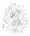
- Fig. 2 is a perspective view showing the internal construction of the projector device.
- a member constituting an optical system of the projector device is omitted from the illustration.
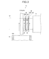
- Fig. 3 is a side view showing an optical modulator.
- the up-and-down direction, the right-and-left direction and the front-and-rear direction represent those directions when the projector device is viewed from the front side thereof while it is installed.
- the projector device 10 is a liquid crystal projector having a light source 12, a color-separating optical system 13, an optical modulator (optical element) 14, a projection lens 15 and a cooling device 16 for the optical modulator 14 which are mounted in a housing 11.
- the housing 11 is a planular box-shaped member constructed by using a raw material having an excellent heat radiation property (for example, magnesium).
- An air suction port 11A for supplying outdoor air into the housing 11 is formed in one side surface of the housing 11, and an air exhaust port 11B having an exhaust fan 17 for exhausting inner air to the outside of the housing is formed in the other side surface.
- a hermetically-sealed chamber 18 which is compartmented as a hermetically-sealed space is provided in the housing 11, and the color-separating optical system 13, the optical modulator 14, a heat sink (heat absorbing unit) 38 described later of the cooling device 16, etc. are mounted in the hermetically-sealed chamber 18.
- the hermetically-sealed is a space in which drift of air (so-called breathing phenomenon) occurs slightly between the inside and outside of the space concerned in connection with temperature variation or the like in the space.
- This hermetically-sealed space is a planular (flat) box-shaped member formed of a member having an excellent adiathermic (heat insulating) property (for example, rubber or plastic type material whose thermal conductivity is equal to about 0.1W/ (m.K) to 0.3W/(m.K) such as hard polyvinyl chloride, silicon resin, fluorocarbon resin, phenol resin, polycarbonate resin, polystyrene resin or the like.
- a member having an excellent adiathermic (heat insulating) property for example, rubber or plastic type material whose thermal conductivity is equal to about 0.1W/ (m.K) to 0.3W/(m.K) such as hard polyvinyl chloride, silicon resin, fluorocarbon resin, phenol resin, polycarbonate resin, polystyrene resin or the like.
- a light transmissible window 18A for leading light emitted from the light source 12 to the color-separating optical system 13 is formed in one side surface confronting the light source 12, and a light transmissible window 18B for leading a projection light image modulated in the optical modulator 14 to the projection lens 15 is formed in the other side surface confronting the projection lens 15.
- the outer surface or inner surface of the box-shaped body thereof may be covered with a member having a high adiathermic property (for example, a material having thermal conductivity of 0.1W/m.K or less such as glass wool, hard polyurethane foam, closed-cell elastomer or the like).
- the light source 12 has a lamp 20 such as an extra high pressure mercury lamp or the like, and a mirror 21 for emitting light diffused from the lamp 20 (diverging light) forwardly.
- the light source 12 has plural (four) lamps 20, and four mirrors 21, and mounted in a lamp box 22 provided in the housing 11.
- the color-separating optical system 13 separates a light flux from the light source into color light of respective colors R, G and B, and it comprises first and second dichroic mirrors 24A and 24B for separating this light flux into the respective color light, reflecting mirrors 25A to 25C for leading the respective separated color light flux to the optical modulator 14, a relay lens (not shown), etc.
- the irradiation light of the light source 12 is forwardly emitted by the mirror 21, and led to the first dichroic mirror 24A through a light transmissible window 18A of the hermetically-sealed chamber 18.
- the first dichroic mirror 24A transmits light of a red wavelength band therethrough and reflects light of a cyan (green + blue) wavelength band.
- the light of the red wavelength band transmitted through the first dichroic mirror 24A is reflected from a reflecting mirror 25A to change the optical path thereof, led to a liquid crystal panel (LCD panel) 27 (described later) as a transmission type display device for red light of the optical modulator 14, and transmitted through the liquid crystal panel 27 to be optically modulated.
- LCD panel liquid crystal panel
- the light of the cyan wavelength band reflected from the first dichroic mirror 24A is led to the second dichroic mirror 24B.
- the second dichroic mirror 24B transmits light of a blue wavelength band and reflects light of a green wavelength band.
- the light of the green wavelength band reflected from the second dichroic mirror 24B is led to a liquid crystal panel (described later) as a green light transmission type display device of the optical modulator 14, and transmitted through the liquid crystal panel 28 to be optically modulated.
- the light of the blue wavelength band transmitted through the second dichroic mirror 24B is passed through total reflection mirrors 25B and 25C, led to a liquid crystal panel 29 (described later) as a blue light transmission type display device of the optical modulator 14 and transmitted through the liquid crystal panel 29 to be optically modulated.
- the light modulator 14 has three liquid crystal panels 27, 28 and 29 corresponding to the respective R, G and B, plural (two in this embodiment) polarizing plates (polarizing panels) provided at the emission side of each of the respective liquid crystal panels 27, 28, 29 so as to be spaced from each other through a gap, etc. IN accordance with video information, the liquid crystal panel 27, 28, 29 modulates light which is separated by the color-separating optical system 13 and then led to each of the liquid crystal panels 27, 28, 29.
- a prism 31 for combining the respective color light to form a projection light image is disposed in a space defined by the respective liquid crystal panels 27, 28 and 29 and the polarizing plates 30.
- This prism 31 corresponds to the color-separating optical system 13, and has a reflection face formed of an X-shaped dielectric multilayer film.
- the light from the respective liquid crystal panels 27, 28 and 29 is set to a single light flux through the reflection face concerned.
- Reference numeral 32 represents a light flux (optical path) through which light emitted from the light source 12 is led to the respective liquid crystal panels 27, 28 and 29 and the polarizing plates 30.
- Each polarizing plate 30 is formed of a member for polarizing light.
- each polarizing plate 30 is constructed by joining a polarizing film 30B of a synthetic resin or the like to the surface of a glass base material 30A formed of sapphire glass so that the polarizing film 30B is slightly larger than the optical path 32, and the polarizing plate 30B is located at the incident side of the polarizing plate 30 as shown in Fig. 3 .
- the liquid crystal panels 27, 28 and 29 and the polarizing plate 30 produce heat when irradiated with light.
- the projection lens 15 projects a projection light image from the prism 31 onto a screen (not shown) while enlarging the light image, and it is detachably mounted in a hole formed in the wall surface of the housing 11.
- Light emitted from the light source 12 is separated into light of respective colors R, G and B in the color-separating optical system 13, and the thus-separated R, G and B light is led to the liquid crystal panels 27, 28, 29 as the corresponding light valves.
- Each light flux led to each liquid crystal panel 27, 28, 29 is modulated in accordance with video information there, passed through the polarizing plates 30 and then becomes a single light-flux projection image in the prism 31 . Thereafter, the projection image concerned is projected onto the screen by the projection lens 15 with being enlarged.
- the cooling device 16 cools the liquid crystal panels 27, 28 and 29, the polarizing plates 30 and the prism 31 of the optical modulator 14, and it has a compressor 35, a radiator 36, an expansion valve 37 and a heat absorber 38. These elements are connected to one another through a pipe to form a refrigerant circuit. That is, a refrigerant discharge pipe 39 of the compressor 35 is connected to the entrance of the radiator 36, and the exist of the radiator 36 is connected to one end of a refrigerant pipe 40.
- the other end of the refrigerant pipe 40 is connected to the entrance of the heat absorber 38 through an electromagnetic opening/closing valve 41 and the expansion valve 37, and the exit of the heat absorber 38 is connected to a refrigerant suction pipe 43 of the compressor 35 through an electromagnetic opening/closing valve 42 to construct an annular refrigeration circuit.
- the radiator 36 is an air-cooling type heat exchanger, and an air blowing fan 44 as air blowing means is disposed in the neighborhood (at the side) of the radiator 36.
- the expansion valve 37 is used as a device for reducing the pressure of refrigerant, however, the pressure-reducing device is not limited to the expansion valve 37. Any device may be adopted insofar as it can reduce the pressure of the refrigerant to a predetermined pressure, and a device using a capillary tube may be used.
- the compressor 35, the radiator 36 and the expansion valve 37 of the cooling device 16 are disposed at the outside of the hermetically-sealed chamber 18, and the heat absorber 38 is disposed in the hermetically-sealed chamber 18. Therefore, the refrigerant pipe 40 and the refrigerant suction pipe 43 are disposed so as to penetrate through the side wall of the hermetically-sealed chamber 18.
- the compressor 35, the radiator 36 and the expansion valve 37 of the cooling device 16 are disposed in proximity to the air suction port 11A of the housing 11.
- the light source is disposed between the cooling device 16 and the air exhaust port 11B. Therefore, an air flowing passage intercommunicating with the air suction port 11A and the air exhaust port 11B is formed between the hermetically-sealed chamber 18 and the side wall of the housing 11 in the housing 11. Air supplied from the air suction port 11A into the housing 11 cools the compressor 35 and the radiator 36 of the cooling device 16, and cools the lamp 20 of the light source 12. Thereafter, the air is discharged from the air exhaust port 11B.
- the temperature of the lamp 20 of the light source 12 increases to a remarkably high temperature than the temperature of the compressor 35 and the radiator 36. Therefore, even after the compressor 35 and the radiator 36 are cooled, the lamp 20 of the light source 12 can be sufficiently cooled.
- a duct 45 is disposed in the hermetically-sealed chamber 18 to supply cooling air cooled in the heat absorber 38 to the liquid crystal panels 27, 28 and 29 and the polarizingplates 30 of the optical modulator 14.
- This duct 45 extends horizontally at the lower portion of the hermetically-sealed chamber 18, one end of the duct 45 is branched to three sub ducts (three systems) in conformity with the respective liquid crystal panels 27, 28 and 29, and air blow-out openings 45A which are upwardly opened are formed at the ends of the branched three sub ducts so as to be located at the lower positions of the respective liquid crystal panels 27, 28 and 29.
- the air blower 46 is mounted at the other end of the duct 45, and an air suction duct 47 extending upwardly in the hermetically-sealed chamber 18 is connected to the upper portion of the air blower 46.
- the air suction opening 47A of the air suction duct 47 is formed to be enlarged in diameter, and the heat absorber 38 is disposed in the air suction opening 47A.
- reference numeral 48 represents an electrical component box in which a control board for controlling the operation of each part of the projector device 10 is mounted.
- the blow-out air is sucked through the air suction opening 47A into the air suction duct 47, and circulated in the hermetically-sealed chamber 18. Accordingly, the temperature of the inside of the hermetically-sealed chamber 18 can be kept uniform, and thus the liquid crystal panels 27, 28 and 29, the polarizing plates 30, etc. can be cooled without being affected by the outdoor air temperature, and the respective equipment such as the liquid crystal panels 27, 28, 29, the polarizing plates 30, etc. provided in the hermetically-sealed chamber 18 can be kept to an optimum constant temperature at all times.
- the polarizing plate 30 is cooled by blowing air from the air blower 46 to the polarizing plate 30 as described above.
- the amount of heat generation from the optical modulator 14 increases, and thus it is required to increase the blowing amount of cooling air by rotating the air blower 46 at high speed. As a result, there is a risk that noise occurring from the air blower 46 increases.
- wires (turbulence promoting member) 50 extending in a direction perpendicular to the flow direction of air blown from the air blow-out opening 45A are disposed at the upper side of the air blow-out opening 45A of the duct 45.
- the wires 50 are disposed at the upstream side of the air stream flowing between the respective two adjacent panels 27, 28, 29, 30 in gaps ⁇ 1, ⁇ 2 between respective two adjacent panels 27, 28, 29, 30. Accordingly, as indicated by arrows in Fig. 3 , the flow of air blown out from the air blow-out opening 45A is disturbed by the wires 50, thereby promoting heat transfer and thus enhancing the cooling efficiency.
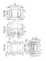
- Figs. 4A to 4D are diagrams showing a support structure of the wires 50, wherein Fig. 4A is a front view showing the support structure of the wires 50, Fig. 4B is a bottom view showing the support structure of the wires 50, Fig. 4C is a side view showing the support structure of the wires 50, and Fig. 4D are A-A cross-sectional views of Figs. 4B and 4C .
- the prism 31 is mounted in a prism frame 51, and a pair of upper and lower panel frames 52 extending to the incident side are fixed to the side surface of the prism frame 51.
- the pair of upper and lower panel frames 52 are designed to be substantially U-shaped in bottom view, and the liquid crystal panels 27, 28 and 29 are fixed to the tip faces of the panel frames 52 through a fixing plate 53 which is secured so as to bridge the pair of upper and lower panel frames 52.
- a pair of polarizing plate supporting frames 54 are fixed to both the side surfaces of the panel frame 52 so as to bridge the pair of upper and lower panel frames 52.
- a pair of upper and lower polarizing plate positioning frames 55 are secured to the prism frame 51.
- Each of the polarizing plate positioning frames 55 has a base portion 55 extending along the front surface of the prism frame 51 to the center, and an extending portion 55B which is branched from the base portion 55A into two parts and extends horizontally to the incident side.
- Each polarizing plate 30 is pinched at both sides thereof by the pair of right and left polarizing plate support frames 54, and also positioned at the upper and lower sides thereof by the extending portions 55B of the polarizing plate positioning frames 55, whereby each polarizing plate 30 is fixed to the panel frame 52.
- Each polarizing plate 30 can be exchanged by merely detaching the polarizing plate support frame 54 from the panel frame 52.
- the wires 50 are disposed in the gap ⁇ 1 between the liquid crystal panel 27, 28, 29 and the polarizing plate 30 and in the gap ⁇ 2 between the two polarizing plates 30.
- Each wire 50 is formed to be longer than the optical path 32, and extends substantially in parallel to the liquid crystal panels 27, 28, 29 and the polarizing plates 30.
- each wire 50 is provided to extend to the right and left sides so as to bridge the pair of right and left extending portions 55B, and fixed to the extending portions 55B by substantially L-shaped fixing members 56.
- the fixing members 56 may be used to fix the wires 50, and thus the wires 50 can be fixed with a simple construction without applying any alteration to the optical modulator 14.
- the fixing members 56 are fixed to the polarizing plate positioning frame 55 which is not detached when the polarizing plate 30 is exchanged, and thus the polarizing plate 30 can be exchanged without detaching the wires 50.
- Fig. 5 is a diagram showing a test device.
- the respective directions such as the up-and-down direction, etc. described below are conformed with the directions shown in Fig. 5 .
- the two polarizing plates 30 are arranged so as to be spaced from each other through the gap ⁇ 2 of 3mm, and adiabatic materials (heat insulators) 101 are fixed to the opposite surfaces to the confronting surfaces.
- a heater 102 extending along the polarizing plate 30 is provided to one (at the lower side in Fig. 5 ) heat insulator 101 so as to come into contact with the polarizing plate 30.
- the heater 102 is formed to have substantially the same size as the optical path 32 ( Fig. 3 ) so as to copy (imitate) light incident to the polarizing plates 30, and heats the polarizing plates 30 in place of light.
- a thermocouple 103 for measuring the temperature of the polarizing plates 30 is provided at the center portion of the polarizing plate 30 adjacent to the heater 102.
- the air blow-out opening 145A of the duct 45 for blowing out air to the polarizing plate 30 is formed to be smaller than the actual air blow-out opening 45A ( Fig. 2 ), and disposed to be near to the polarizing plates 30. Furthermore, a flow rate measuring unit (not shown) for measuring the flow rate of air passing between the two polarizing plates 30 is provided to the test device 100.
- the thus-constructed test device 100 is a device which has sufficient correlation with the actual projector device 10 ( Fig. 2 ) and can obtain substantially the same result as the projector device 10.
- the room temperature under test is set to 25°C.
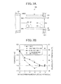
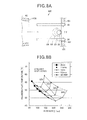
- Figs. 6A and 6B are diagrams showing the test for changing the arrangement position of the wires 50 along the gap ⁇ 2 direction, wherein Fig. 6A is a cross-sectional showing the arrangement position of the wire 50 and Fig. 6B is a diagram showing a test result.
- the abscissa axis represents the flow rate
- the ordinate axis represents the temperature of the polarizing plate.
- a wire 50 which is formed to be circular in cross-sectional shape and have a diameter of 1mm is used.
- This wire 50 is located inside the polarizing plates 30, more specifically, is located in proximity to the heater 102 and at the substantially center position, the upper side or the lower side between the two polarizing plates 30 as shown in Fig. 6A .
- the arrangement position of the wire 50 is defined as a wire center condition when the wire 50 is located at the substantially center position, as a wire upper condition when the wire 50 is located at the upper side and as a wire lower condition when the wire 50 is located at the lower side.
- an input voltage of the air blower 46 ( Fig. 2 ) is varied to 10V, 17V and 24V respectively, and the temperature of the center portion of the polarizing plate 30 (polarizing plate temperature) is also measured even when no wire 50 is arranged (no wire condition) .
- the polarizing plate temperature decreases to a lower value irrespective of the value of the input voltage of the air blower 46 ( Fig. 2 ) when the wire 50 ( Fig. 6A ) is arranged as compared with the case where no wire 50 is arranged. Furthermore, the polarizing plate temperature is substantially equal irrespective of the value of the input voltage of the air blower 46 between the wire center condition and the wire upper condition (i.e., when the wire 50 is substantially center position and when the wire 50 is located at the upper position). However, when the wire 50 is located at the lower side (wire lower condition), the polarizing temperature decreases to a lower value as compared with the wire center condition and the wire upper condition.
- the polarizing temperature is lower by about 3°C when the wire 50 is located at the lower position (wire lower condition) than when the wire 50 is not arranged. Accordingly, the wire 50 is disposed in proximity to a site which is required to be cooled, for example, the polarizing film 30B ( Fig. 3 ), thereby promoting heat transfer and thus enhancing the cooling efficiency.
- Figs. 7A and 7B are diagrams showing a test in which the arrangement position of the wire 50 is changed along the air flowing direction, wherein Fig. 7A is a cross-sectional view showing the arrangement position of the wire 50, and Fig. 7B is a diagram showing a test result.
- the abscissa axis represents the distance from the end portion of the polarizing plate
- the ordinate axis at the left side represents the flow rate
- the ordinate axis at the right side represents the polarizing plate temperature.
- a wire 50 having a circular cross-sectional shape and a diameter of 1mm is used, and this wire 50 is disposed at the lower side between the two polarizing plates 30 and located to be far away from the end portion 30C of the polarizing plate 30 at a distance L of 0mm, 2mm, 1mm, 3mm, 4mm, 5mm.
- the distance from the end portion 30C of the polarizing plate 30 to the heater 102 is set to 6mm.
- the temperature of the polarizing plate 30 is measured even when the wire 50 is located at the substantially center position between the two polarizing plates 30 and the distance L is set to 5mm (wire center condition).
- the flow rate is little different as compared with the case where the wire 50 is located at the lower side and the distance L is set to 5mm, however, the polarizing plate temperature is lower by about 3.5°C when the wire 50 is located at the lower side as compared with the case where the wire 50 is located at the substantially center position. Accordingly, the wire 50 is disposed in proximity to the optical path 32 without obstructing the optical path 32 ( Fig. 3 ) , whereby the heat transfer can be promoted and the cooling efficiency can be enhanced.
- Figs. 8A and 8B are diagrams showing a test in which the diameter of the wire 50 is changed, wherein Fig. 8A is a cross-sectional view showing the arrangement position of the wire 50, and Fig. 8B is a diagram showing a test result.
- the abscissa axis represents the flow rate
- the ordinate axis represents the polarizing plate temperature.
- Fig. 8A in this test, four kinds of wires 50 having a circular cross-sectional shape and a diameter of 0.5mm, 1mm, 1.5mm and 2mm are used. Each wire 50 is located in proximity to the heater 2 (optical path 32 ( Fig. 3 )) and located at the substantially center position between the two polarizing plates 30.
- the input voltage of the air blower 46 Fig. 2
- the input voltage of the air blower 46 is varied to 12V, 16V, 20V and 24V, and even when the wire 50 is not arranged, the temperature of the polarizing plate 30 is measured.
- the polarizing plate temperature is lower when the four kinds of wires 50 ( Fig. 8A ) are arranged as compared with the case where no wire 50 is arranged. Furthermore, irrespective of the value of the input voltage of the air blower 46, the polarizing plate temperature is lowest when the diameter is equal to 1mm, and it increases in the order of 1.5mm, 0.5mm and 2mm in diameter. Accordingly, by setting the diameter of the wire 50 to 1mm, the heat transfer can be promoted, and the cooling efficiency can be enhanced.
- Figs. 9A and 9B are diagrams showing a test in which the cross-sectional shape of the wire 50 is changed, wherein Fig. 9A is a diagram showing the cross-sectional shape of the wire 50, and Fig. 9B is a diagram showing a test result.
- the gap ⁇ 2 between the two polarizing plates 30 is equal to 3mm. Therefore, with respect to the circle condition of 1mm in diameter, the upward triangle condition of 1mm in one side, the downward triangle condition of 1mm in one side and the rectangle condition of 1mm in one side, the blockage ratio in the flow direction between the two polarizing plates 30 is equal to 1/3, and with respect to the rhomboid condition of 1mm in one side, the blockage ratio in the flow direction between the two polarizing plates 30 is equal to 1.41/3.
- each wire 50 is located in proximity to the heater 102 (optical path 32 ( Fig. 3 )), and at the lower side between the two polarizing plates 30. Furthermore, in this test, the input voltage of the air blower 46 ( Fig. 2 ) is varied to 12V, 16V and 20V, and the temperature of the polarizing plate 30 is measured even when no wire 50 is arranged.
- the polarizing plate temperature decreases to a lower value when the wires 50 having different cross-sectional shapes ( Fig. 9A ) are arranged as compared with the case where no wire 50 is arranged. Furthermore, the flow rate is lowest in the case of the rhomboid condition irrespective of the value of the input voltage of the air blower 46, and it increases in the order of the rectangle condition, the downward triangle condition and the circle condition.
- the polarizing plate temperature is lowest in the case of the rectangle condition irrespective of the value of the input voltage of the air blower 46, and it increases in the order of the circle condition, the downward triangle condition, the upward triangle condition and the rhomboid condition. Accordingly, the wire 50 having the rectangular cross-sectional shape is formed, and this wire 50 is arranged while one side thereof faces the air flow, whereby the heat transfer can be promoted and the cooling efficiency can be enhanced.
- two wires 50 having a rectangular cross-sectional shape whose one side is equal to 1mm are used so that the dimension of the outer shape thereof is equal to substantially one third of the gap ⁇ 2 between the two polarizing plates 30.
- Each of the wires 50 is arranged so that one side thereof faces the air flow, and also arranged in proximity to the optical path 32 so as to be near to the polarizing film 30B. Accordingly, turbulence generated by the wires 50 is kept in the neighborhood of the center of the polarizing plates 30 and at the downstream side of the polarizing plates 30, so that the heat transfer can be promoted and the cooling efficiency can be enhanced. Therefore, with respect to even the projector device which can project a high-brightness picture, it is unnecessary to increase the rotational speed of the air blower 46 ( Fig. 2 ) and thus noise occurring from the air blower 46 can be suppressed.
- the wire 50 which is provided at the upstream position of the air stream flowing between the two adjacent panels 27, 28, 29, 30 so as to extend in a direction perpendicular to the air flow is disposed in the gap between the two adjacent panels 27, 28, 29, 30. Therefore, as compared with the case where the wire is disposed at the upper side of the two adjacent panels , the wire 50 is disposed at the center side of the panels 27, 28, 29, 30. Therefore, turbulence generated by the wire 50 can be kept even in the neighborhood of the center of the panels 27, 28, 29, 30 and at the downstream side, so that the heat transfer can be promoted and the cooling efficiency can be enhanced.
- the wires 50 are disposed in proximity to the optical paths 32 of the panels 27, 28, 30, and thus the wires 50 are disposed at the center side of the panels 27, 28, 29, 30. Therefore, the turbulence generated by the wires 50 can be kept even in the neighborhood of and at the downstream side of the panels 27, 28, 29, 30, so that the heat transfer can be promoted and the cooling efficiency can be enhanced.
- the wire 50 is disposed so as to be near to (in proximity to or approach to) the incident face of the polarizing plate 30. Therefore, the incident faces of the polarizing plates 30 which are near to the liquid crystal panels 27, 28, 29 and easily increased to relatively high temperature are more greatly cooled, and thus the polarizing plates 30 can be effectively cooled.
- the polarizing plate 30 is formed by joining polarizing film 30B to the surface of a glass base material 30A, and the wire 50 is disposed to be near to the polarizing film 30B. Therefore, the polarizing film 30B can be more greatly cooled, and reduction of the polarizing function of the polarizing plate 30 can be suppressed, so that the lifetime of the polarizing plate 30 can be increased.
- the cross-section of the wire 50 is designed in a rectangular shape whose one side is perpendicular to air flow (air stream). Therefore, the polarizing plate 30 can be more greatly cooled as compared with a case where a wire having another cross-sectional shape is arranged.
- the outer shape of the wire 50 is formed so that the size thereof is substantially one third (1/3) of the gap ⁇ 2 between the two adjacent panels 30. Therefore, the polarizing plates 30 can be more greatly cooled as compared with a case where a wire whose outer shape is another size is disposed.
- the wires 50 are disposed in both the gap ⁇ 1 between the liquid crystal panel 27, 28, 29 and the polarizing plate 30 and the gap ⁇ 2 between the two polarizing plates 30, however, the wires 50 may be disposed in any one of the gap ⁇ 1 and the gap ⁇ 2.
- the wire 50 is provided so as to bridge a pair of right and left extending portions 55B, however, it may be provided so as to bridge a pair of upper and lower extending portions 55B.
- the wires 50 are respectively provided in the gap ⁇ 1 between the liquid crystal panel 27, 28, 29 and the polarizing plate and the gap ⁇ 2 between the two polarizing plates 30 one by one, however, plural wires 50 may be provided in each of the gaps ⁇ 1 and ⁇ 2.
- the polarizing plate 30 is disposed at the emission side of each of the liquid crystal panels 27, 28, 29, however, the polarizing plates 30 may be disposed at both the emission side and the incident side.
- the wire 50 may be disposed between the two polarizing plates adjacent to the incident side and/or between the liquid crystal panel 27, 28, 29 and the incident-side polarizing plate 30 which are adjacent to each other.
- the wire is used as the turbulence promoting member.
- the turbulence promoting member is not limited to the wire, and for example a planar member may be used.
- the air blower 46 makes air cooled by the cooling device 46 flow to the optical modulator 14, however, it may make non-cooled air to the optical modulator 14.
Landscapes
- Physics & Mathematics (AREA)
- General Physics & Mathematics (AREA)
- Engineering & Computer Science (AREA)
- Multimedia (AREA)
- Signal Processing (AREA)
- Projection Apparatus (AREA)
- Transforming Electric Information Into Light Information (AREA)
Abstract
In a projector device having a light source (12), a plurality of panels (27, 28, 29, 30) for modulating light emitted from the light source in accordance with video information, the panels containing a liquid crystal panel (27, 28, 29) and a plurality of polarizing panels (30) arranged in parallel, an air blower (46) for blowing air to the liquid crystal panel and the plurality of polarizing panels, and a housing (11) in which the light source, the liquid crystal panel, the polarizing panels and the air blower are mounted, a turbulence promoting member (50) for disturbing an air stream flowing between two adjacent panels is provided at an upstream position of the air stream in a gap between the two adjacent panels so as to extend in a direction perpendicular to the air stream.
Description
- The present invention relates to a projector device for modulating light emitted from a light source by an optical element, and a projection light image after the modulation onto a screen by a projection lens.
- There is known a projector device including a light source, an optical element for modulating light emitted from the light source in accordance with video information, a projection lens for projecting a modulated projection light image onto a screen, and an air blower for blowing air to the optical element to cool the optical element (for example, see
JP-A-2003-066534 - However, in the construction of the above projector, the turbulence promoting member is disposed at the upstream side of the optical element, and thus turbulence flow is reduced at a place which is far away from the turbulence flow promoting member, for example, in the neighborhood of the center of the optical element or at the downstream side of the optical element. Therefore, the heat transfer effect is insufficient, and the cooling efficiency is not sufficiently enhanced.
- Therefore, an object of the present invention is to solve the above problem of the conventional technique and provide a projector device that enhances a cooling efficiency.
- In order to attain the above object, a projector device having a light source (12), a plurality of panels (27, 28, 29, 30) for modulating light emitted from the light source in accordance with video information, the panels containing a liquid crystal panel (27, 28, 29) and a plurality of polarizing panels (30) arranged in parallel, an air blower (46) for blowing air to the liquid crystal panel and the plurality of polarizing panels, and a housing (11) in which the light source, the liquid crystal panel, the polarizing panels and the air blower are mounted, is characterized in that a turbulence promoting member (50) for disturbing an air stream flowing between two adjacent panels is provided at an upstream position of the air stream in a gap between the two adjacent panels so as to extend in a direction perpendicular to the air stream.
- In the above projector device, the turbulence promoting member is disposed in proximity to an optical path of the panel.
- In the above projector device, the turbulence promoting member is disposed to be near to an incident face of the polarizing panel.
- In the above projector device, each of the polarizing panels is formed by joining polarizing film to a surface of a glass base material, and the turbulence promoting member is disposed to be near to the polarizing film.
- In the above projector device, the cross-sectional shape of the turbulence promoting member is designed in a rectangular shape whose one side is perpendicular to the air stream.
- In the above projector device, the turbulence promoting member is designed to have an outer shape whose dimension is substantially equal to substantially one third of the gap between two adjacent panels.
- According to the present invention, the turbulence promoting member for disturbing an air stream flowing between two adjacent panels is provided at an upstream position of the air stream in a gap between the two adjacent panels so as to extend in a direction perpendicular to the air stream. Therefore, turbulence generated by the turbulence promoting member can be kept even in the neighborhood of the panels and at the downstream side of the air stream, so that the heat transfer can be promoted and the cooling efficiency can be enhanced.
-
-
Fig. 1 is a diagram showing the construction of a projector device according to an embodiment of the present invention; -
Fig. 2 is a perspective view showing the internal construction of the projector device; -
Fig. 3 is a side view showing an optical modulator; -
Figs. 4A to 4D show a wire support structure, whereinFig. 4A is a front view of the wire support structure,Fig. 4B is a bottom view showing the wire support structure,Fig. 4C is a side view showing the wire support structure, andFig. 4D is a cross-sectional view taken along A-A line ofFig. 4C ; -
Fig. 5 is a side view showing an experiment device; -
Figs. 6A and 6B are diagrams showing an experiment in which a wire arrangement position is changed along a gap direction, whereinFig. 6A is a cross-sectional view showing the wire arrangement position, andFig. 6B is a diagram showing an experiment result; -
Figs. 7A and 7B are diagrams showing an experiment in which the wire arrangement position is changed along an air flowing direction, whereinFig. 7A is a cross-sectional view showing the wire arrangement position, andFig. 7B is a diagram showing an experiment result; -
Figs. 8A and 8B are diagrams showing an experiment in which the diameter of the wire is changed, whereinFig. 8A is a cross-sectional view showing the arrangement position of the wire, andFig. 8B is a diagram showing an experiment result; and -
Figs. 9A and 9B are diagrams showing an experiment in which the wire diameter is changed, whereinFig. 9A is a diagram showing the cross-sectional shape of the wire, andFig. 9B is a diagram showing an experiment result. - Preferred embodiments according to the present invention will be described hereunder with reference to the accompanying drawings.
-
Fig. 1 is a diagram showing the construction of a projector device according to an embodiment, andFig. 2 is a perspective view showing the internal construction of the projector device. InFig. 2 , a member constituting an optical system of the projector device is omitted from the illustration.Fig. 3 is a side view showing an optical modulator. In the following description, the up-and-down direction, the right-and-left direction and the front-and-rear direction represent those directions when the projector device is viewed from the front side thereof while it is installed. - As shown in
Fig. 1 , theprojector device 10 is a liquid crystal projector having alight source 12, a color-separatingoptical system 13, an optical modulator (optical element) 14, aprojection lens 15 and acooling device 16 for theoptical modulator 14 which are mounted in ahousing 11. Thehousing 11 is a planular box-shaped member constructed by using a raw material having an excellent heat radiation property (for example, magnesium). Anair suction port 11A for supplying outdoor air into thehousing 11 is formed in one side surface of thehousing 11, and anair exhaust port 11B having anexhaust fan 17 for exhausting inner air to the outside of the housing is formed in the other side surface. - A hermetically-sealed
chamber 18 which is compartmented as a hermetically-sealed space is provided in thehousing 11, and the color-separatingoptical system 13, theoptical modulator 14, a heat sink (heat absorbing unit) 38 described later of thecooling device 16, etc. are mounted in the hermetically-sealedchamber 18. Here, the hermetically-sealed is a space in which drift of air (so-called breathing phenomenon) occurs slightly between the inside and outside of the space concerned in connection with temperature variation or the like in the space. This hermetically-sealed space is a planular (flat) box-shaped member formed of a member having an excellent adiathermic (heat insulating) property (for example, rubber or plastic type material whose thermal conductivity is equal to about 0.1W/ (m.K) to 0.3W/(m.K) such as hard polyvinyl chloride, silicon resin, fluorocarbon resin, phenol resin, polycarbonate resin, polystyrene resin or the like. A lighttransmissible window 18A for leading light emitted from thelight source 12 to the color-separatingoptical system 13 is formed in one side surface confronting thelight source 12, and a lighttransmissible window 18B for leading a projection light image modulated in theoptical modulator 14 to theprojection lens 15 is formed in the other side surface confronting theprojection lens 15. with respect to the hermetically-sealedchamber 18, the outer surface or inner surface of the box-shaped body thereof may be covered with a member having a high adiathermic property (for example, a material having thermal conductivity of 0.1W/m.K or less such as glass wool, hard polyurethane foam, closed-cell elastomer or the like). - The
light source 12 has alamp 20 such as an extra high pressure mercury lamp or the like, and amirror 21 for emitting light diffused from the lamp 20 (diverging light) forwardly. In this embodiment, thelight source 12 has plural (four)lamps 20, and fourmirrors 21, and mounted in alamp box 22 provided in thehousing 11. - The color-separating
optical system 13 separates a light flux from the light source into color light of respective colors R, G and B, and it comprises first and seconddichroic mirrors mirrors 25A to 25C for leading the respective separated color light flux to theoptical modulator 14, a relay lens (not shown), etc. - The irradiation light of the
light source 12 is forwardly emitted by themirror 21, and led to the firstdichroic mirror 24A through a lighttransmissible window 18A of the hermetically-sealedchamber 18. The firstdichroic mirror 24A transmits light of a red wavelength band therethrough and reflects light of a cyan (green + blue) wavelength band. The light of the red wavelength band transmitted through the firstdichroic mirror 24A is reflected from a reflectingmirror 25A to change the optical path thereof, led to a liquid crystal panel (LCD panel) 27 (described later) as a transmission type display device for red light of theoptical modulator 14, and transmitted through theliquid crystal panel 27 to be optically modulated. - Furthermore, the light of the cyan wavelength band reflected from the first
dichroic mirror 24A is led to the seconddichroic mirror 24B. The seconddichroic mirror 24B transmits light of a blue wavelength band and reflects light of a green wavelength band. The light of the green wavelength band reflected from the seconddichroic mirror 24B is led to a liquid crystal panel (described later) as a green light transmission type display device of theoptical modulator 14, and transmitted through theliquid crystal panel 28 to be optically modulated. - Furthermore, the light of the blue wavelength band transmitted through the second
dichroic mirror 24B is passed through total reflection mirrors 25B and 25C, led to a liquid crystal panel 29 (described later) as a blue light transmission type display device of theoptical modulator 14 and transmitted through theliquid crystal panel 29 to be optically modulated. - The
light modulator 14 has threeliquid crystal panels liquid crystal panels liquid crystal panel optical system 13 and then led to each of theliquid crystal panels - A
prism 31 for combining the respective color light to form a projection light image is disposed in a space defined by the respectiveliquid crystal panels polarizing plates 30. Thisprism 31 corresponds to the color-separatingoptical system 13, and has a reflection face formed of an X-shaped dielectric multilayer film. The light from the respectiveliquid crystal panels Reference numeral 32 represents a light flux (optical path) through which light emitted from thelight source 12 is led to the respectiveliquid crystal panels polarizing plates 30. - Each
polarizing plate 30 is formed of a member for polarizing light. For example, eachpolarizing plate 30 is constructed by joining apolarizing film 30B of a synthetic resin or the like to the surface of aglass base material 30A formed of sapphire glass so that thepolarizing film 30B is slightly larger than theoptical path 32, and thepolarizing plate 30B is located at the incident side of thepolarizing plate 30 as shown inFig. 3 . Theliquid crystal panels polarizing plate 30 produce heat when irradiated with light. - As shown in
Fig. 2 , theprojection lens 15 projects a projection light image from theprism 31 onto a screen (not shown) while enlarging the light image, and it is detachably mounted in a hole formed in the wall surface of thehousing 11. - The operation of the optical system of the
projector 10 described above will be described. - Light emitted from the
light source 12 is separated into light of respective colors R, G and B in the color-separatingoptical system 13, and the thus-separated R, G and B light is led to theliquid crystal panels liquid crystal panel polarizing plates 30 and then becomes a single light-flux projection image in theprism 31 . Thereafter, the projection image concerned is projected onto the screen by theprojection lens 15 with being enlarged. - Next, the
cooling device 16 will be described. - The
cooling device 16 cools theliquid crystal panels polarizing plates 30 and theprism 31 of theoptical modulator 14, and it has acompressor 35, aradiator 36, anexpansion valve 37 and aheat absorber 38. These elements are connected to one another through a pipe to form a refrigerant circuit. That is, arefrigerant discharge pipe 39 of thecompressor 35 is connected to the entrance of theradiator 36, and the exist of theradiator 36 is connected to one end of arefrigerant pipe 40. The other end of therefrigerant pipe 40 is connected to the entrance of theheat absorber 38 through an electromagnetic opening/closingvalve 41 and theexpansion valve 37, and the exit of theheat absorber 38 is connected to arefrigerant suction pipe 43 of thecompressor 35 through an electromagnetic opening/closingvalve 42 to construct an annular refrigeration circuit. Theradiator 36 is an air-cooling type heat exchanger, and anair blowing fan 44 as air blowing means is disposed in the neighborhood (at the side) of theradiator 36. In this embodiment, theexpansion valve 37 is used as a device for reducing the pressure of refrigerant, however, the pressure-reducing device is not limited to theexpansion valve 37. Any device may be adopted insofar as it can reduce the pressure of the refrigerant to a predetermined pressure, and a device using a capillary tube may be used. - In this construction, the
compressor 35, theradiator 36 and theexpansion valve 37 of thecooling device 16 are disposed at the outside of the hermetically-sealedchamber 18, and theheat absorber 38 is disposed in the hermetically-sealedchamber 18. Therefore, therefrigerant pipe 40 and therefrigerant suction pipe 43 are disposed so as to penetrate through the side wall of the hermetically-sealedchamber 18. - The
compressor 35, theradiator 36 and theexpansion valve 37 of thecooling device 16 are disposed in proximity to theair suction port 11A of thehousing 11. The light source is disposed between the coolingdevice 16 and theair exhaust port 11B. Therefore, an air flowing passage intercommunicating with theair suction port 11A and theair exhaust port 11B is formed between the hermetically-sealedchamber 18 and the side wall of thehousing 11 in thehousing 11. Air supplied from theair suction port 11A into thehousing 11 cools thecompressor 35 and theradiator 36 of thecooling device 16, and cools thelamp 20 of thelight source 12. Thereafter, the air is discharged from theair exhaust port 11B. The temperature of thelamp 20 of thelight source 12 increases to a remarkably high temperature than the temperature of thecompressor 35 and theradiator 36. Therefore, even after thecompressor 35 and theradiator 36 are cooled, thelamp 20 of thelight source 12 can be sufficiently cooled. - As shown in
Fig. 2 , aduct 45 is disposed in the hermetically-sealedchamber 18 to supply cooling air cooled in theheat absorber 38 to theliquid crystal panels polarizingplates 30 of theoptical modulator 14. Thisduct 45 extends horizontally at the lower portion of the hermetically-sealedchamber 18, one end of theduct 45 is branched to three sub ducts (three systems) in conformity with the respectiveliquid crystal panels openings 45A which are upwardly opened are formed at the ends of the branched three sub ducts so as to be located at the lower positions of the respectiveliquid crystal panels air blower 46 is mounted at the other end of theduct 45, and anair suction duct 47 extending upwardly in the hermetically-sealedchamber 18 is connected to the upper portion of theair blower 46. Theair suction opening 47A of theair suction duct 47 is formed to be enlarged in diameter, and theheat absorber 38 is disposed in theair suction opening 47A. InFig. 2 ,reference numeral 48 represents an electrical component box in which a control board for controlling the operation of each part of theprojector device 10 is mounted. - When the
air blower 46 is operated, air in the hermetically-sealed chamber is sucked through the air suction opening 47A into theair suction duct 47. At this time, the sucked air is deprived of heat by refrigerant flowing through theheat absorber 38 while passing through theheat absorber 38. The cooled air flows through theduct 45, and is supplied through the air blow-outopening 45A of theduct 45 to the respectiveliquid crystal panels polarizing plates 30. Accordingly, theliquid crystal panels polarizing plates 30 radiate heat to the supplied air to be cooled, and then blown into the hermetically-sealedchamber 18. The blow-out air is sucked through the air suction opening 47A into theair suction duct 47, and circulated in the hermetically-sealedchamber 18. Accordingly, the temperature of the inside of the hermetically-sealedchamber 18 can be kept uniform, and thus theliquid crystal panels polarizing plates 30, etc. can be cooled without being affected by the outdoor air temperature, and the respective equipment such as theliquid crystal panels polarizing plates 30, etc. provided in the hermetically-sealedchamber 18 can be kept to an optimum constant temperature at all times. - When the temperature of the
polarizing film 30B exceeds a limit temperature, the polarizing function of thepolarizing plate 30 is remarkably lowered. Therefore, thepolarizing plate 30 is cooled by blowing air from theair blower 46 to thepolarizing plate 30 as described above. However, in the projector device in which pictures of high brightness can be projected, the amount of heat generation from theoptical modulator 14 increases, and thus it is required to increase the blowing amount of cooling air by rotating theair blower 46 at high speed. As a result, there is a risk that noise occurring from theair blower 46 increases. - Therefore, according to this embodiment, in order to cool the
optical modulator 14 with a small amount of flowing air, wires (turbulence promoting member) 50 extending in a direction perpendicular to the flow direction of air blown from the air blow-outopening 45A are disposed at the upper side of the air blow-outopening 45A of theduct 45. Thewires 50 are disposed at the upstream side of the air stream flowing between the respective twoadjacent panels adjacent panels Fig. 3 , the flow of air blown out from the air blow-outopening 45A is disturbed by thewires 50, thereby promoting heat transfer and thus enhancing the cooling efficiency. -
Figs. 4A to 4D are diagrams showing a support structure of thewires 50, whereinFig. 4A is a front view showing the support structure of thewires 50,Fig. 4B is a bottom view showing the support structure of thewires 50,Fig. 4C is a side view showing the support structure of thewires 50, andFig. 4D are A-A cross-sectional views ofFigs. 4B and 4C . - The
prism 31 is mounted in aprism frame 51, and a pair of upper and lower panel frames 52 extending to the incident side are fixed to the side surface of theprism frame 51. The pair of upper and lower panel frames 52 are designed to be substantially U-shaped in bottom view, and theliquid crystal panels plate 53 which is secured so as to bridge the pair of upper and lower panel frames 52. A pair of polarizingplate supporting frames 54 are fixed to both the side surfaces of thepanel frame 52 so as to bridge the pair of upper and lower panel frames 52. - A pair of upper and lower polarizing plate positioning frames 55 are secured to the
prism frame 51. Each of the polarizing plate positioning frames 55 has abase portion 55 extending along the front surface of theprism frame 51 to the center, and an extendingportion 55B which is branched from thebase portion 55A into two parts and extends horizontally to the incident side. Eachpolarizing plate 30 is pinched at both sides thereof by the pair of right and left polarizing plate support frames 54, and also positioned at the upper and lower sides thereof by the extendingportions 55B of the polarizing plate positioning frames 55, whereby eachpolarizing plate 30 is fixed to thepanel frame 52. Eachpolarizing plate 30 can be exchanged by merely detaching the polarizingplate support frame 54 from thepanel frame 52. - The
wires 50 are disposed in the gap δ1 between theliquid crystal panel polarizing plate 30 and in the gap δ2 between the twopolarizing plates 30. Eachwire 50 is formed to be longer than theoptical path 32, and extends substantially in parallel to theliquid crystal panels polarizing plates 30. - Furthermore, each
wire 50 is provided to extend to the right and left sides so as to bridge the pair of right and left extendingportions 55B, and fixed to the extendingportions 55B by substantially L-shapedfixing members 56. Accordingly, the fixingmembers 56 may be used to fix thewires 50, and thus thewires 50 can be fixed with a simple construction without applying any alteration to theoptical modulator 14. Furthermore, the fixingmembers 56 are fixed to the polarizingplate positioning frame 55 which is not detached when thepolarizing plate 30 is exchanged, and thus thepolarizing plate 30 can be exchanged without detaching thewires 50. - In order to further reduce the temperature of the
polarizing plates 30, a test of measuring the temperature of thepolarizing plates 30 while changing the arrangement position and shape of thewires 50 was performed. -
Fig. 5 is a diagram showing a test device. The respective directions such as the up-and-down direction, etc. described below are conformed with the directions shown inFig. 5 . - In the
test device 100, the twopolarizing plates 30 are arranged so as to be spaced from each other through the gap δ2 of 3mm, and adiabatic materials (heat insulators) 101 are fixed to the opposite surfaces to the confronting surfaces. Aheater 102 extending along thepolarizing plate 30 is provided to one (at the lower side inFig. 5 )heat insulator 101 so as to come into contact with thepolarizing plate 30. Theheater 102 is formed to have substantially the same size as the optical path 32 (Fig. 3 ) so as to copy (imitate) light incident to thepolarizing plates 30, and heats thepolarizing plates 30 in place of light. Athermocouple 103 for measuring the temperature of thepolarizing plates 30 is provided at the center portion of thepolarizing plate 30 adjacent to theheater 102. - The air blow-out
opening 145A of theduct 45 for blowing out air to thepolarizing plate 30 is formed to be smaller than the actual air blow-outopening 45A (Fig. 2 ), and disposed to be near to thepolarizing plates 30. Furthermore, a flow rate measuring unit (not shown) for measuring the flow rate of air passing between the twopolarizing plates 30 is provided to thetest device 100. - The thus-constructed
test device 100 is a device which has sufficient correlation with the actual projector device 10 (Fig. 2 ) and can obtain substantially the same result as theprojector device 10. The room temperature under test is set to 25°C. - A test in which the arrangement position of the
wires 50 is changed along the direction of the gap δ2 and the temperature of the polarizing plate is measured will be described. -
Figs. 6A and 6B are diagrams showing the test for changing the arrangement position of thewires 50 along the gap δ2 direction, whereinFig. 6A is a cross-sectional showing the arrangement position of thewire 50 andFig. 6B is a diagram showing a test result. InFig. 6B , the abscissa axis represents the flow rate, and the ordinate axis represents the temperature of the polarizing plate. - As shown in
Fig. 6A , in this test, awire 50 which is formed to be circular in cross-sectional shape and have a diameter of 1mm is used. Thiswire 50 is located inside thepolarizing plates 30, more specifically, is located in proximity to theheater 102 and at the substantially center position, the upper side or the lower side between the twopolarizing plates 30 as shown inFig. 6A . Here, the arrangement position of thewire 50 is defined as a wire center condition when thewire 50 is located at the substantially center position, as a wire upper condition when thewire 50 is located at the upper side and as a wire lower condition when thewire 50 is located at the lower side. Furthermore, in this test, an input voltage of the air blower 46 (Fig. 2 ) is varied to 10V, 17V and 24V respectively, and the temperature of the center portion of the polarizing plate 30 (polarizing plate temperature) is also measured even when nowire 50 is arranged (no wire condition) . - As shown in
Fig. 6B , the polarizing plate temperature decreases to a lower value irrespective of the value of the input voltage of the air blower 46 (Fig. 2 ) when the wire 50 (Fig. 6A ) is arranged as compared with the case where nowire 50 is arranged. Furthermore, the polarizing plate temperature is substantially equal irrespective of the value of the input voltage of theair blower 46 between the wire center condition and the wire upper condition (i.e., when thewire 50 is substantially center position and when thewire 50 is located at the upper position). However, when thewire 50 is located at the lower side (wire lower condition), the polarizing temperature decreases to a lower value as compared with the wire center condition and the wire upper condition. Particularly, when the input voltage of theair blower 46 is equal to 24V, the polarizing temperature is lower by about 3°C when thewire 50 is located at the lower position (wire lower condition) than when thewire 50 is not arranged. Accordingly, thewire 50 is disposed in proximity to a site which is required to be cooled, for example, thepolarizing film 30B (Fig. 3 ), thereby promoting heat transfer and thus enhancing the cooling efficiency. - Next, a test in which the arrangement position of the
wire 5 is changed along the air flowing direction and the temperature of thepolarizing plate 30 is measured will be described. -
Figs. 7A and 7B are diagrams showing a test in which the arrangement position of thewire 50 is changed along the air flowing direction, whereinFig. 7A is a cross-sectional view showing the arrangement position of thewire 50, andFig. 7B is a diagram showing a test result. InFig. 7B , the abscissa axis represents the distance from the end portion of the polarizing plate, the ordinate axis at the left side represents the flow rate, and the ordinate axis at the right side represents the polarizing plate temperature. - As shown in
Fig. 7A , according to this test, awire 50 having a circular cross-sectional shape and a diameter of 1mm is used, and thiswire 50 is disposed at the lower side between the twopolarizing plates 30 and located to be far away from theend portion 30C of thepolarizing plate 30 at a distance L of 0mm, 2mm, 1mm, 3mm, 4mm, 5mm. In this embodiment, the distance from theend portion 30C of thepolarizing plate 30 to the heater 102 (optical path (Fig. 3 )) is set to 6mm. In this test, the temperature of thepolarizing plate 30 is measured even when thewire 50 is located at the substantially center position between the twopolarizing plates 30 and the distance L is set to 5mm (wire center condition). - As shown in
Fig. 7B , when the wire 50 (Fig. 7A ) is arranged at the lower side and moved along the air flowing direction, the flow rate decreases as the distance L is shifted from 0mm to 3mm, and the when the distance L is equal to 4mm and 5mm, the flow rate slightly increases as compared with the distance L is equal to 3mm. With respect to the polarizing plate temperature, as the distance L is longer, as thewire 50 is disposed to be nearer to the center side of thepolarizing plate 30, the polarizing plate temperature decreases. Furthermore, when thewire 50 is located at the substantially center position and the distance L is set to 5mm, the flow rate is little different as compared with the case where thewire 50 is located at the lower side and the distance L is set to 5mm, however, the polarizing plate temperature is lower by about 3.5°C when thewire 50 is located at the lower side as compared with the case where thewire 50 is located at the substantially center position. Accordingly, thewire 50 is disposed in proximity to theoptical path 32 without obstructing the optical path 32 (Fig. 3 ) , whereby the heat transfer can be promoted and the cooling efficiency can be enhanced. - Next, a test in which the diameter of the
wire 50 is changed and the temperature of thepolarizing plate 30 is measured will be described. -
Figs. 8A and 8B are diagrams showing a test in which the diameter of thewire 50 is changed, whereinFig. 8A is a cross-sectional view showing the arrangement position of thewire 50, andFig. 8B is a diagram showing a test result. InFig. 8B , the abscissa axis represents the flow rate, and the ordinate axis represents the polarizing plate temperature. - As shown in
Fig. 8A , in this test, four kinds ofwires 50 having a circular cross-sectional shape and a diameter of 0.5mm, 1mm, 1.5mm and 2mm are used. Eachwire 50 is located in proximity to the heater 2 (optical path 32 (Fig. 3 )) and located at the substantially center position between the twopolarizing plates 30. In this test, the input voltage of the air blower 46 (Fig. 2 ) is varied to 12V, 16V, 20V and 24V, and even when thewire 50 is not arranged, the temperature of thepolarizing plate 30 is measured. - As shown in
Fig. 8B , irrespective of the value of the input voltage of the air blower 46 (Fig. 2 ), the polarizing plate temperature is lower when the four kinds of wires 50 (Fig. 8A ) are arranged as compared with the case where nowire 50 is arranged. Furthermore, irrespective of the value of the input voltage of theair blower 46, the polarizing plate temperature is lowest when the diameter is equal to 1mm, and it increases in the order of 1.5mm, 0.5mm and 2mm in diameter. Accordingly, by setting the diameter of thewire 50 to 1mm, the heat transfer can be promoted, and the cooling efficiency can be enhanced. - Next, a test in which the cross-sectional shape of the
wire 50 is changed to measure the temperature of thepolarizing plate 30 will be described. -
Figs. 9A and 9B are diagrams showing a test in which the cross-sectional shape of thewire 50 is changed, whereinFig. 9A is a diagram showing the cross-sectional shape of thewire 50, andFig. 9B is a diagram showing a test result. - As shown in
Fig. 9A , in this test, three kinds ofwires 50 whose cross-sectional shapes are a circle of 1mm in diameter, a triangle of 1mm in side length and a rectangle of 1mm in side length. When acircular wire 50 is arranged, this arrangement is defined as a circle condition. When atriangular wire 50 is arranged while one apex thereof faces the air flow (air flowing direction), this arrangement is defined as an upward triangle condition. When atriangular wire 50 is arranged while one side thereof faces the air flow, this arrangement is defined as a downward triangle condition. Furthermore, when arectangular wire 50 is arranged while one side thereof faces the air flow, this arrangement is defined as a rectangle condition. When arectangular wire 50 is arranged while one apex thereof faces the air flow, this arrangement is defined as a rhomboid condition. - Here, the gap δ2 between the two
polarizing plates 30 is equal to 3mm. Therefore, with respect to the circle condition of 1mm in diameter, the upward triangle condition of 1mm in one side, the downward triangle condition of 1mm in one side and the rectangle condition of 1mm in one side, the blockage ratio in the flow direction between the twopolarizing plates 30 is equal to 1/3, and with respect to the rhomboid condition of 1mm in one side, the blockage ratio in the flow direction between the twopolarizing plates 30 is equal to 1.41/3. - As shown in
Fig. 5 , eachwire 50 is located in proximity to the heater 102 (optical path 32 (Fig. 3 )), and at the lower side between the twopolarizing plates 30. Furthermore, in this test, the input voltage of the air blower 46 (Fig. 2 ) is varied to 12V, 16V and 20V, and the temperature of thepolarizing plate 30 is measured even when nowire 50 is arranged. - As shown in
Fig. 9B , irrespective of the value of the input voltage of the air blower 46 (Fig. 2 ), the polarizing plate temperature decreases to a lower value when thewires 50 having different cross-sectional shapes (Fig. 9A ) are arranged as compared with the case where nowire 50 is arranged. Furthermore, the flow rate is lowest in the case of the rhomboid condition irrespective of the value of the input voltage of theair blower 46, and it increases in the order of the rectangle condition, the downward triangle condition and the circle condition. On the other hand, the polarizing plate temperature is lowest in the case of the rectangle condition irrespective of the value of the input voltage of theair blower 46, and it increases in the order of the circle condition, the downward triangle condition, the upward triangle condition and the rhomboid condition. Accordingly, thewire 50 having the rectangular cross-sectional shape is formed, and thiswire 50 is arranged while one side thereof faces the air flow, whereby the heat transfer can be promoted and the cooling efficiency can be enhanced. - According to this embodiment, on the basis of the above test results, two
wires 50 having a rectangular cross-sectional shape whose one side is equal to 1mm are used so that the dimension of the outer shape thereof is equal to substantially one third of the gap δ2 between the twopolarizing plates 30. Each of thewires 50 is arranged so that one side thereof faces the air flow, and also arranged in proximity to theoptical path 32 so as to be near to thepolarizing film 30B. Accordingly, turbulence generated by thewires 50 is kept in the neighborhood of the center of thepolarizing plates 30 and at the downstream side of thepolarizing plates 30, so that the heat transfer can be promoted and the cooling efficiency can be enhanced. Therefore, with respect to even the projector device which can project a high-brightness picture, it is unnecessary to increase the rotational speed of the air blower 46 (Fig. 2 ) and thus noise occurring from theair blower 46 can be suppressed. - As described above, according to this embodiment, the
wire 50 which is provided at the upstream position of the air stream flowing between the twoadjacent panels adjacent panels wire 50 is disposed at the center side of thepanels wire 50 can be kept even in the neighborhood of the center of thepanels - According to this embodiment, the
wires 50 are disposed in proximity to theoptical paths 32 of thepanels wires 50 are disposed at the center side of thepanels wires 50 can be kept even in the neighborhood of and at the downstream side of thepanels - According to this embodiment, the
wire 50 is disposed so as to be near to (in proximity to or approach to) the incident face of thepolarizing plate 30. Therefore, the incident faces of thepolarizing plates 30 which are near to theliquid crystal panels polarizing plates 30 can be effectively cooled. - Furthermore, according to this embodiment, the
polarizing plate 30 is formed by joiningpolarizing film 30B to the surface of aglass base material 30A, and thewire 50 is disposed to be near to thepolarizing film 30B. Therefore, thepolarizing film 30B can be more greatly cooled, and reduction of the polarizing function of thepolarizing plate 30 can be suppressed, so that the lifetime of thepolarizing plate 30 can be increased. - Still furthermore, according to this embodiment, the cross-section of the
wire 50 is designed in a rectangular shape whose one side is perpendicular to air flow (air stream). Therefore, thepolarizing plate 30 can be more greatly cooled as compared with a case where a wire having another cross-sectional shape is arranged. - Still furthermore, according to this embodiment, the outer shape of the
wire 50 is formed so that the size thereof is substantially one third (1/3) of the gap δ2 between the twoadjacent panels 30. Therefore, thepolarizing plates 30 can be more greatly cooled as compared with a case where a wire whose outer shape is another size is disposed. - The present invention is not limited to the above embodiment, and various modifications may be made without departing from the subject matter of the present invention.
- For example, in the above embodiment, the
wires 50 are disposed in both the gap δ1 between theliquid crystal panel polarizing plate 30 and the gap δ2 between the twopolarizing plates 30, however, thewires 50 may be disposed in any one of the gap δ1 and the gap δ2. - Furthermore, in the above embodiment, the
wire 50 is provided so as to bridge a pair of right and left extendingportions 55B, however, it may be provided so as to bridge a pair of upper and lower extendingportions 55B. - In the above embodiment, the
wires 50 are respectively provided in the gap δ1 between theliquid crystal panel polarizing plates 30 one by one, however,plural wires 50 may be provided in each of the gaps δ1 and δ2. - Furthermore, in the above embodiment, the
polarizing plate 30 is disposed at the emission side of each of theliquid crystal panels polarizing plates 30 may be disposed at both the emission side and the incident side. In this case, thewire 50 may be disposed between the two polarizing plates adjacent to the incident side and/or between theliquid crystal panel polarizing plate 30 which are adjacent to each other. - In the above embodiment, the wire is used as the turbulence promoting member. However, the turbulence promoting member is not limited to the wire, and for example a planar member may be used.
- Furthermore, in the above embodiment, the
air blower 46 makes air cooled by the coolingdevice 46 flow to theoptical modulator 14, however, it may make non-cooled air to theoptical modulator 14.
Claims (6)
- A projector device having a light source (12), a plurality of panels (27, 28, 29, 30) for modulating light emitted from the light source in accordance with video information, the panels containing a liquid crystal panel (27, 28, 29) and a plurality of polarizing panels (30) arranged in parallel, an air blower (46) for blowing air to the liquid crystal panel and the plurality of polarizing panels, and a housing (11) in which the light source, the liquid crystal panel, the polarizing panels and the air blower are mounted, characterized in that a turbulence promoting member (50) for disturbing an air stream flowing between two adjacent panels is provided at an upstream position of the air stream in a gap between the two adjacent panels so as to extend in a direction perpendicular to the air stream.
- The projector device according to claim 1, wherein the turbulence promoting member is disposed in proximity to an optical path of the panel.
- The projector device according to claim 1 or 2, wherein the turbulence promoting member is disposed to be near to an incident face of the polarizing panel.
- The projector device according to any one of claims 1 to 3, wherein each of the polarizing panels is formed by joining polarizing film to a surface of a glass base material, and the turbulence promoting member is disposed to be near to the polarizing film.
- The projector device according to any one of claims 1 to 4, wherein the cross-sectional shape of the turbulence promoting member is designed in a rectangular shape whose one side is perpendicular to the air stream.
- The projector device according to any one of claims 1 to 5, wherein the turbulence promoting member is designed to have an outer shape whose dimension is substantially equal to substantially one third of the gap between two adjacent panels.
Applications Claiming Priority (1)
| Application Number | Priority Date | Filing Date | Title |
|---|---|---|---|
| JP2010042284A JP2011180241A (en) | 2010-02-26 | 2010-02-26 | Projector device |
Publications (1)
| Publication Number | Publication Date |
|---|---|
| EP2367054A1 true EP2367054A1 (en) | 2011-09-21 |
Family
ID=44070709
Family Applications (1)
| Application Number | Title | Priority Date | Filing Date |
|---|---|---|---|
| EP11155390A Withdrawn EP2367054A1 (en) | 2010-02-26 | 2011-02-22 | Turbulent air stream for cooling a liquid crystal panel |
Country Status (4)
| Country | Link |
|---|---|
| US (1) | US20110211166A1 (en) |
| EP (1) | EP2367054A1 (en) |
| JP (1) | JP2011180241A (en) |
| CN (1) | CN102169280A (en) |
Families Citing this family (13)
| Publication number | Priority date | Publication date | Assignee | Title |
|---|---|---|---|---|
| JP5831185B2 (en) * | 2011-12-06 | 2015-12-09 | トヨタ自動車株式会社 | Solar heat collector |
| JP5867037B2 (en) * | 2011-12-07 | 2016-02-24 | セイコーエプソン株式会社 | projector |
| JP6218387B2 (en) * | 2013-02-04 | 2017-10-25 | キヤノン株式会社 | Projection display |
| CN106444241A (en) * | 2015-08-04 | 2017-02-22 | 海信集团有限公司 | Laser light source and laser projection display device |
| CN106814527B (en) | 2015-10-07 | 2019-04-23 | 精工爱普生株式会社 | projector |
| EP3235777A1 (en) * | 2016-04-18 | 2017-10-25 | Carlsberg Breweries A/S | A beverage font assembly for being mounted on a bar counter of a drinking establishment and a method of monitoring a beverage font assembly mounted on a bar counter in a drinking establishment |
| JP6996533B2 (en) * | 2019-08-20 | 2022-01-17 | セイコーエプソン株式会社 | projector |
| JP7322726B2 (en) * | 2020-01-29 | 2023-08-08 | セイコーエプソン株式会社 | projector |
| CN211348977U (en) * | 2020-02-07 | 2020-08-25 | 中强光电股份有限公司 | Opto-mechanical modules and projectors |
| JP7052816B2 (en) * | 2020-03-19 | 2022-04-12 | セイコーエプソン株式会社 | projector |
| JP2021157057A (en) * | 2020-03-27 | 2021-10-07 | セイコーエプソン株式会社 | projector |
| JP2022070675A (en) | 2020-10-27 | 2022-05-13 | セイコーエプソン株式会社 | projector |
| CN113448148B (en) * | 2021-07-27 | 2022-04-01 | 深圳市科金明电子股份有限公司 | Accurate focusing device and focusing method for projector |
Citations (5)
| Publication number | Priority date | Publication date | Assignee | Title |
|---|---|---|---|---|
| JP2000194073A (en) * | 1998-12-28 | 2000-07-14 | Fujitsu Ltd | Projection display device |
| JP2001125057A (en) * | 1999-10-25 | 2001-05-11 | Nec Viewtechnology Ltd | Projection display device |
| JP2003066534A (en) | 2001-08-28 | 2003-03-05 | Sanyo Electric Co Ltd | Cooling structure of optical parts of LCD projector |
| US20080252859A1 (en) * | 2007-04-12 | 2008-10-16 | Sony Corporation | Projection display device |
| JP2008292743A (en) * | 2007-05-24 | 2008-12-04 | Necディスプレイソリューションズ株式会社 | Cooling device, and electronic equipment and projection type display device equipped with cooling device |
-
2010
- 2010-02-26 JP JP2010042284A patent/JP2011180241A/en active Pending
-
2011
- 2011-02-17 US US13/029,568 patent/US20110211166A1/en not_active Abandoned
- 2011-02-22 EP EP11155390A patent/EP2367054A1/en not_active Withdrawn
- 2011-02-25 CN CN201110046472.7A patent/CN102169280A/en active Pending
Patent Citations (5)
| Publication number | Priority date | Publication date | Assignee | Title |
|---|---|---|---|---|
| JP2000194073A (en) * | 1998-12-28 | 2000-07-14 | Fujitsu Ltd | Projection display device |
| JP2001125057A (en) * | 1999-10-25 | 2001-05-11 | Nec Viewtechnology Ltd | Projection display device |
| JP2003066534A (en) | 2001-08-28 | 2003-03-05 | Sanyo Electric Co Ltd | Cooling structure of optical parts of LCD projector |
| US20080252859A1 (en) * | 2007-04-12 | 2008-10-16 | Sony Corporation | Projection display device |
| JP2008292743A (en) * | 2007-05-24 | 2008-12-04 | Necディスプレイソリューションズ株式会社 | Cooling device, and electronic equipment and projection type display device equipped with cooling device |
Also Published As
| Publication number | Publication date |
|---|---|
| JP2011180241A (en) | 2011-09-15 |
| US20110211166A1 (en) | 2011-09-01 |
| CN102169280A (en) | 2011-08-31 |
Similar Documents
| Publication | Publication Date | Title |
|---|---|---|
| US20110211166A1 (en) | Projector device | |
| US7237906B2 (en) | Projection-type image display apparatus | |
| CN101535891B (en) | Projector | |
| JP7036911B2 (en) | Electronic devices and projectors | |
| KR100683171B1 (en) | Radiator and projector with it | |
| US7481540B2 (en) | Projection display device and cooling structure | |
| US6966653B2 (en) | Cooling device and optical device and projector having the cooling device | |
| US8303118B2 (en) | Video projector | |
| WO2006003898A1 (en) | Liquid crystal projector, its liquid crystal panel, and its liquid cooler | |
| JP3639271B2 (en) | Projection display device and blower | |
| JP2005121250A (en) | Cooling device and rear projector | |
| US20130077054A1 (en) | Projector and display apparatus having the same | |
| CN106814527A (en) | Projecting apparatus | |
| JP2009163075A (en) | Projection type video display apparatus | |
| CN100410807C (en) | Projection Video Display | |
| JP2007025403A (en) | Projector | |
| KR100646243B1 (en) | Cooling plate for projector using cover | |
| JP4467483B2 (en) | Projector device | |
| JP4065284B2 (en) | Projector device | |
| JP2000305470A (en) | Display device | |
| JP2007025406A (en) | Projector | |
| WO2019224992A1 (en) | Electronic device and projector | |
| JP2005121249A (en) | Cooling device and rear projector | |
| JP4187735B2 (en) | Projector device | |
| KR100800200B1 (en) | Color wheel cooling structure of the projection system. |
Legal Events
| Date | Code | Title | Description |
|---|---|---|---|
| PUAI | Public reference made under article 153(3) epc to a published international application that has entered the european phase |
Free format text: ORIGINAL CODE: 0009012 |
|
| 17P | Request for examination filed |
Effective date: 20110222 |
|
| AK | Designated contracting states |
Kind code of ref document: A1 Designated state(s): AL AT BE BG CH CY CZ DE DK EE ES FI FR GB GR HR HU IE IS IT LI LT LU LV MC MK MT NL NO PL PT RO RS SE SI SK SM TR |
|
| AX | Request for extension of the european patent |
Extension state: BA ME |
|
| STAA | Information on the status of an ep patent application or granted ep patent |
Free format text: STATUS: THE APPLICATION HAS BEEN WITHDRAWN |
|
| 18W | Application withdrawn |
Effective date: 20120326 |