EP2366996A1 - Inspection device utilizing eddy currents - Google Patents
Inspection device utilizing eddy currents Download PDFInfo
- Publication number
- EP2366996A1 EP2366996A1 EP11156026A EP11156026A EP2366996A1 EP 2366996 A1 EP2366996 A1 EP 2366996A1 EP 11156026 A EP11156026 A EP 11156026A EP 11156026 A EP11156026 A EP 11156026A EP 2366996 A1 EP2366996 A1 EP 2366996A1
- Authority
- EP
- European Patent Office
- Prior art keywords
- component
- sensor assembly
- eddy current
- probe body
- probe
- Prior art date
- Legal status (The legal status is an assumption and is not a legal conclusion. Google has not performed a legal analysis and makes no representation as to the accuracy of the status listed.)
- Withdrawn
Links
Images

Classifications
-
- G—PHYSICS
- G01—MEASURING; TESTING
- G01N—INVESTIGATING OR ANALYSING MATERIALS BY DETERMINING THEIR CHEMICAL OR PHYSICAL PROPERTIES
- G01N27/00—Investigating or analysing materials by the use of electric, electrochemical, or magnetic means
- G01N27/72—Investigating or analysing materials by the use of electric, electrochemical, or magnetic means by investigating magnetic variables
- G01N27/82—Investigating or analysing materials by the use of electric, electrochemical, or magnetic means by investigating magnetic variables for investigating the presence of flaws
- G01N27/90—Investigating or analysing materials by the use of electric, electrochemical, or magnetic means by investigating magnetic variables for investigating the presence of flaws using eddy currents
- G01N27/9046—Investigating or analysing materials by the use of electric, electrochemical, or magnetic means by investigating magnetic variables for investigating the presence of flaws using eddy currents by analysing electrical signals
- G01N27/9053—Compensating for probe to workpiece spacing
-
- G—PHYSICS
- G01—MEASURING; TESTING
- G01B—MEASURING LENGTH, THICKNESS OR SIMILAR LINEAR DIMENSIONS; MEASURING ANGLES; MEASURING AREAS; MEASURING IRREGULARITIES OF SURFACES OR CONTOURS
- G01B7/00—Measuring arrangements characterised by the use of electric or magnetic techniques
- G01B7/14—Measuring arrangements characterised by the use of electric or magnetic techniques for measuring distance or clearance between spaced objects or spaced apertures
-
- G—PHYSICS
- G01—MEASURING; TESTING
- G01M—TESTING STATIC OR DYNAMIC BALANCE OF MACHINES OR STRUCTURES; TESTING OF STRUCTURES OR APPARATUS, NOT OTHERWISE PROVIDED FOR
- G01M15/00—Testing of engines
- G01M15/14—Testing gas-turbine engines or jet-propulsion engines
Definitions
- This invention relates generally to an inspection device. More particularly, this invention relates to an inspection probe that utilizes eddy currents.
- Turbo machinery such as gas turbine engines are known and include multiple sections, such as a fan section, a compression section, a combustor section, and a turbine section.
- the fan section moves air into the machinery.
- the air is compressed as the air flows through the compression section.
- the compressed air is then mixed with fuel and combusted in the combustor section. Products of the combustion are expanded in the turbine section to rotatably drive the machinery.
- the performance of the machinery depends, in part, on relationships and interfaces between components of the machinery. Accordingly, components of the machinery are periodically inspected to determine their dimensions, clearances, spacing, and other information. The information obtained during the inspection can highlight potential relationship and interface issues.
- disks in the turbine section of an engine include slots for holding turbine blades.
- the slots have a relatively complex geometry and are sometimes difficult to measure due to their axial depth. The dimensions of the slots change when the disk erodes during cleaning. The slots in the eroded disk may fail to securely hold the turbine blades.
- An example turbine machinery inspection probe device includes a sensor assembly configured to induce an eddy current in a turbine machinery component.
- a probe body holds a tip of the sensor assembly in a position spaced from a target surface of the turbine machinery component when the probe body is in contact with a portion of the turbine machinery component.
- the sensor assembly senses a parameter of the eddy current in the turbine machinery component and uses the sensed parameter to calculate the position of the target surface relative to the probe body.
- Another example inspection probe device includes a sensor assembly configured to induce an eddy current in a component.
- a probe body houses at least a portion of the sensor assembly such that the portion of the sensor assembly is spaced from a target surface of the component when the probe body is in contact with the component.
- a controller is used to calculate the location of the target surface relative to the probe body using an eddy current parameter sensed by the sensor assembly.
- An example method of inspecting a component includes securing an inspection probe relative to a component and using a sensor assembly housed within the inspection probe to induce an eddy current in a target area of the component.
- the target area has a target surface that is spaced from the sensor assembly.
- the method further includes sensing an eddy current parameter in the component using the sensor assembly and determining a position of the first surface of the component relative to the inspection probe using the eddy current parameter sensed in said step (c).
- Figure 1 schematically illustrates an example gas turbine engine 10, which is an example type of turbine machinery.
- the example gas turbine engine 10 includes (in serial flow communication) a fan section 14, a low-pressure compressor 18, a high-pressure compressor 22, a combustor 26, a high-pressure turbine 30, and a low-pressure turbine 34.
- the gas turbine engine 10 is circumferentially disposed about an engine centerline X.
- air is pulled into the gas turbine engine 10 by the fan section 14. Some of the air moves to a core of the gas turbine engine 10 and is pressurized by the compressors 18 and 22, mixed with fuel, and burned in the combustor 26.
- the turbines 30 and 34 extract energy from the hot combustion gases flowing from the combustor 26.
- the high-pressure turbine 30 utilizes the extracted energy from the hot combustion gases to power the high-pressure compressor 22 through a high speed shaft 38
- the low-pressure turbine 34 utilizes the extracted energy from the hot combustion gases to power the low-pressure compressor 18 and the fan section 14 through a low speed shaft 42.
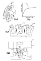
- an example inspection probe assembly 50 includes a multiple of eddy current sensors 54 housed in a probe body 58.
- the eddy current sensors 54 form a portion of an eddy current sensor assembly.
- the eddy current sensors 54 are linked to a controller 62 and an eddy current generator 64, which also form a portion of the example eddy current sensor assembly.
- Access holes 65 in the probe body 58 facilitate securing the sensor tips 54 relative to the probe body 58.
- a pneumatic cylinder 66 is mounted to a housing 70 and the probe body 58.
- the cylinder 66 is configured to move the probe body 58 and the eddy current sensors 54 relative to the housing 70.
- a pin arrangement 74 secures the probe body 58 to a shaft of the cylinder 66.
- the example inspection probe assembly 50 is used to determine dimensions of a turbine blade slot 78 established within a turbine disk 82 of the gas turbine engine 10.
- the turbine disk 82 and the turbine blade slot 78 are components of the high-pressure turbine 30 in this example.
- the turbine blade slot 78 is configured to slidably receive a turbine blade.
- processes used to clean the disk can alter the profile of the turbine blade slot 78.
- the example inspection probe assembly 50 can identify altered areas of the turbine blade slot 78.
- the probe body 58 includes a plurality of teeth 86a-86c configured to be received within a corresponding area 90a-90c of the disk 82.
- the example probe body 58 is configured to have a profile that is similar to the profile of the slot 78.
- the probe body 58 is sized such that the teeth 86b contact the disk 82, and the teeth 86a and 86c are spaced from the disk 82 when the inspection probe assembly 50 is in the installed position shown in Figure 4 .
- the installed position is a position appropriate for determining spacing of the slot 78.
- the probe body 58 is first slid axially into the slot 78. Cylindrical stops 94 limit the axial sliding movement in this example.
- the cylinder 66 is then activated, which pulls the probe body 58 radially outward relative to the housing 70. Contact between the teeth 86b and the disk 82 limits further radial movement of the probe body 58. In another example, the probe body 58 is moved manually rather than using the cylinder 66.
- a surface of the probe body 58 contacts the disk 82 at the teeth 86b.
- the probe body 58 is made from a glass reinforced plastic material. Other suitable materials include other materials that are not likely to scratch or otherwise mar the surfaces of the disk 82.
- the eddy current sensors 54 in the area of the teeth 86b contacting the disk 82 are positioned below the surface of the probe body 58 such that the eddy current sensors 54 in this area are spaced from the disk 82.
- the eddy current sensors 54 in other areas of the probe body 58 are also positioned below the surface of the probe body 58. In another example, these eddy current sensors 54 are flush with the surface of the probe body 58. As can be appreciated, eddy current sensors 54 flush with the surface of the probe body 58 in the other areas would still be spaced from the disk 82 as these other areas of the probe body 58 are spaced from the disk 82.
- the teeth 86b contact the disk 82 at reference surfaces 98.
- Dimensions and other measurements associated with the slot 78 are established, in part, using the location of the reference surfaces 98.
- the eddy current sensors 54 are distributed throughout the probe body 58. Each of the eddy current sensors 54 is configured to induce an eddy current in an associated area of the disk 82. Each of those areas have a target surface 102 that establishes a portion of the slot 78. In this example, the target surface 102 corresponds to the area of the disk 82 closest to the respective eddy current sensor tip 54.
- the eddy current sensors 54 are positioned in various radial and axial positions within the probe body 58. Target surfaces 102 are thus also distributed in this manner.
- the eddy current sensors 54 After inducing the eddy current, the eddy current sensors 54 detect a parameter of the eddy current such as the voltage of the eddy current in that area of the disk 82. A computer 106, using the strength of the voltage, then determines a distance between each of the eddy current sensors 54 and the associated target surface 102. The computer 106 acts as a data acquisition and analysis system for the inspection probe assembly 50.
- the computer 106 associates one of the eddy current sensors 54 detecting a lower eddy current voltage as being spaced closer to the target area 102 associated with that eddy current sensor tip 54 than another eddy current sensor tip 54 that detects a higher eddy current in another target surface 102.
- the computer 106 utilizes a lift-off curve 110 ( figure 5 ) when determining more precise spacing.
- the computer 106 then establishes dimensions of the slot 78, for example, using the distances between each of the eddy current sensors 54 and their associated target surface 102.
- the computer 106 also uses the location of the reference surface 98 in one example.
- the positioning of the probe body 58 relative to the slot 78 is reproducible in another slot 78a.
- the computer 106 may output a comparison of spacing in the slot 78 to the slot 78a. Aligning the probe body 58 relative to the reference surfaces 98 in the slot 78, and the aligning the reference surfaces 98a in the slot 78a facilitates reproducing the position of the probe body 58.
- the cylinder 66 is deactivated so that the probe body 58 can be moved from the installed position within the slot 78 to an installed position within the slot 78a.
- the dimensioning of the probe body 58 and the eddy current sensors 54 is known and remains consistent and stable whether the probe body 58 is in the slot 78 or the slot 78a.
- differences in voltages detected by the eddy current sensors 54 can typically be attributed to differences in the surfaces of the slots 78 and 78a.
- the example computer 106 uses the dimensions to detect dimensional irregularities in the slot 78.
- the dimensional information is compared to acceptable dimensions to determine irregularities.
- the computer 106 may establish a general profile of the slot 78 using the dimensional information.
- features of this invention include a relatively simple inspection tool that is easily transported, installed, and set-up.
- the invention also provides information about variations in the surface along the axial depth of the inspected component.
Landscapes
- Chemical & Material Sciences (AREA)
- Physics & Mathematics (AREA)
- General Physics & Mathematics (AREA)
- Life Sciences & Earth Sciences (AREA)
- Chemical Kinetics & Catalysis (AREA)
- Electrochemistry (AREA)
- Health & Medical Sciences (AREA)
- Analytical Chemistry (AREA)
- Biochemistry (AREA)
- General Health & Medical Sciences (AREA)
- Immunology (AREA)
- Pathology (AREA)
- Combustion & Propulsion (AREA)
- Engineering & Computer Science (AREA)
- Investigating Or Analyzing Materials By The Use Of Magnetic Means (AREA)
- Measurement Of Length, Angles, Or The Like Using Electric Or Magnetic Means (AREA)
Abstract
An inspection probe device (50) includes a sensor assembly configured to induce an eddy current in a component (82). A probe body (58) houses at least a portion (54) of the sensor assembly such that the portion of the sensor assembly is spaced from a target surface (102) of the component (82) when the probe body (58) is in contact with the component (82). A controller (62) is used to calculate the location of the target surface (102) relative to the probe body (58) using an eddy current parameter sensed by the sensor assembly.

Description
- This invention relates generally to an inspection device. More particularly, this invention relates to an inspection probe that utilizes eddy currents.
- Turbo machinery, such as gas turbine engines are known and include multiple sections, such as a fan section, a compression section, a combustor section, and a turbine section. During stable operation, the fan section moves air into the machinery. The air is compressed as the air flows through the compression section. The compressed air is then mixed with fuel and combusted in the combustor section. Products of the combustion are expanded in the turbine section to rotatably drive the machinery.
- The performance of the machinery depends, in part, on relationships and interfaces between components of the machinery. Accordingly, components of the machinery are periodically inspected to determine their dimensions, clearances, spacing, and other information. The information obtained during the inspection can highlight potential relationship and interface issues.
- For example, the size of components can change as the components wear during machinery operation, machinery cleaning, machinery maintenance, etc. Worn components can result in inefficiencies. In one specific example, disks in the turbine section of an engine include slots for holding turbine blades. The slots have a relatively complex geometry and are sometimes difficult to measure due to their axial depth. The dimensions of the slots change when the disk erodes during cleaning. The slots in the eroded disk may fail to securely hold the turbine blades.
- An example turbine machinery inspection probe device includes a sensor assembly configured to induce an eddy current in a turbine machinery component. A probe body holds a tip of the sensor assembly in a position spaced from a target surface of the turbine machinery component when the probe body is in contact with a portion of the turbine machinery component. The sensor assembly senses a parameter of the eddy current in the turbine machinery component and uses the sensed parameter to calculate the position of the target surface relative to the probe body.
- Another example inspection probe device includes a sensor assembly configured to induce an eddy current in a component. A probe body houses at least a portion of the sensor assembly such that the portion of the sensor assembly is spaced from a target surface of the component when the probe body is in contact with the component. A controller is used to calculate the location of the target surface relative to the probe body using an eddy current parameter sensed by the sensor assembly.
- An example method of inspecting a component includes securing an inspection probe relative to a component and using a sensor assembly housed within the inspection probe to induce an eddy current in a target area of the component. The target area has a target surface that is spaced from the sensor assembly. The method further includes sensing an eddy current parameter in the component using the sensor assembly and determining a position of the first surface of the component relative to the inspection probe using the eddy current parameter sensed in said step (c).
- These and other features of the example disclosure can be best understood from the following specification and drawings, the following of which is a brief description:
-
-
Figure 1 shows a cross-section of an example gas turbine engine. -
Figure 2 shows a perspective view of an example inspection probe. -
Figure 3 shows a perspective view of a probe body in theFigure 2 inspection probe. -
Figure 4 shows a perspective view of an example disk of theFigure 1 engine having a blade slot. -
Figure 5 shows a partial schematic side view of theFigure 2 inspection probe in an installed position within theFigure 3 blade slot. -
Figure 6 shows an example lift-off curve used to determine a position of a component in theFigure 1 engine. -
Figure 1 schematically illustrates an examplegas turbine engine 10, which is an example type of turbine machinery. The examplegas turbine engine 10 includes (in serial flow communication) afan section 14, a low-pressure compressor 18, a high-pressure compressor 22, acombustor 26, a high-pressure turbine 30, and a low-pressure turbine 34. Thegas turbine engine 10 is circumferentially disposed about an engine centerline X. - During operation, air is pulled into the
gas turbine engine 10 by thefan section 14. Some of the air moves to a core of thegas turbine engine 10 and is pressurized by thecompressors 18 and 22, mixed with fuel, and burned in thecombustor 26. Theturbines combustor 26. - In a two-spool design, the high-
pressure turbine 30 utilizes the extracted energy from the hot combustion gases to power the high-pressure compressor 22 through ahigh speed shaft 38, and the low-pressure turbine 34 utilizes the extracted energy from the hot combustion gases to power the low-pressure compressor 18 and thefan section 14 through alow speed shaft 42. - The examples described in this disclosure are not limited to the two-spool engine architecture described, however, and may be used in other architectures, such as a single-spool axial design, a three-spool axial design, and still other architectures. Further, although the examples discussed herein are described with regard to the
gas turbine engine 10, those having skill in this art and the benefit of this disclosure will understand that other examples may include other types of turbine machinery or any component comprising at least some conductive material. - Referring to
Figures 2-5 with continuing reference toFigure 1 , an exampleinspection probe assembly 50 includes a multiple of eddycurrent sensors 54 housed in aprobe body 58. The eddycurrent sensors 54 form a portion of an eddy current sensor assembly. The eddycurrent sensors 54 are linked to acontroller 62 and an eddycurrent generator 64, which also form a portion of the example eddy current sensor assembly.Access holes 65 in theprobe body 58 facilitate securing thesensor tips 54 relative to theprobe body 58. - In this example, a
pneumatic cylinder 66 is mounted to ahousing 70 and theprobe body 58. Thecylinder 66 is configured to move theprobe body 58 and the eddycurrent sensors 54 relative to thehousing 70. Apin arrangement 74 secures theprobe body 58 to a shaft of thecylinder 66. - The example
inspection probe assembly 50 is used to determine dimensions of aturbine blade slot 78 established within aturbine disk 82 of thegas turbine engine 10. Theturbine disk 82 and theturbine blade slot 78 are components of the high-pressure turbine 30 in this example. Theturbine blade slot 78 is configured to slidably receive a turbine blade. - As known, processes used to clean the disk, such as grit blasting processes, can alter the profile of the
turbine blade slot 78. The exampleinspection probe assembly 50 can identify altered areas of theturbine blade slot 78. - The
probe body 58 includes a plurality ofteeth 86a-86c configured to be received within acorresponding area 90a-90c of thedisk 82. Theexample probe body 58 is configured to have a profile that is similar to the profile of theslot 78. - In this example, the
probe body 58 is sized such that theteeth 86b contact thedisk 82, and theteeth disk 82 when theinspection probe assembly 50 is in the installed position shown inFigure 4 . The installed position is a position appropriate for determining spacing of theslot 78. - To move the
inspection probe assembly 50 to the installed position, theprobe body 58 is first slid axially into theslot 78.Cylindrical stops 94 limit the axial sliding movement in this example. - The
cylinder 66 is then activated, which pulls theprobe body 58 radially outward relative to thehousing 70. Contact between theteeth 86b and thedisk 82 limits further radial movement of theprobe body 58. In another example, theprobe body 58 is moved manually rather than using thecylinder 66. - In this example, a surface of the
probe body 58 contacts thedisk 82 at theteeth 86b. Theprobe body 58 is made from a glass reinforced plastic material. Other suitable materials include other materials that are not likely to scratch or otherwise mar the surfaces of thedisk 82. - Notably, the
eddy current sensors 54 in the area of theteeth 86b contacting thedisk 82 are positioned below the surface of theprobe body 58 such that theeddy current sensors 54 in this area are spaced from thedisk 82. - The
eddy current sensors 54 in other areas of theprobe body 58 are also positioned below the surface of theprobe body 58. In another example, theseeddy current sensors 54 are flush with the surface of theprobe body 58. As can be appreciated,eddy current sensors 54 flush with the surface of theprobe body 58 in the other areas would still be spaced from thedisk 82 as these other areas of theprobe body 58 are spaced from thedisk 82. - In this example, the
teeth 86b contact thedisk 82 at reference surfaces 98. Dimensions and other measurements associated with theslot 78 are established, in part, using the location of the reference surfaces 98. - The
eddy current sensors 54 are distributed throughout theprobe body 58. Each of theeddy current sensors 54 is configured to induce an eddy current in an associated area of thedisk 82. Each of those areas have atarget surface 102 that establishes a portion of theslot 78. In this example, thetarget surface 102 corresponds to the area of thedisk 82 closest to the respective eddycurrent sensor tip 54. Theeddy current sensors 54 are positioned in various radial and axial positions within theprobe body 58. Target surfaces 102 are thus also distributed in this manner. - After inducing the eddy current, the
eddy current sensors 54 detect a parameter of the eddy current such as the voltage of the eddy current in that area of thedisk 82. Acomputer 106, using the strength of the voltage, then determines a distance between each of theeddy current sensors 54 and the associatedtarget surface 102. Thecomputer 106 acts as a data acquisition and analysis system for theinspection probe assembly 50. - The
computer 106 associates one of theeddy current sensors 54 detecting a lower eddy current voltage as being spaced closer to thetarget area 102 associated with that eddycurrent sensor tip 54 than another eddycurrent sensor tip 54 that detects a higher eddy current in anothertarget surface 102. In one example, thecomputer 106 utilizes a lift-off curve 110 (figure 5 ) when determining more precise spacing. - The
computer 106 then establishes dimensions of theslot 78, for example, using the distances between each of theeddy current sensors 54 and their associatedtarget surface 102. Thecomputer 106 also uses the location of thereference surface 98 in one example. - The positioning of the
probe body 58 relative to theslot 78 is reproducible in anotherslot 78a. Thus thecomputer 106 may output a comparison of spacing in theslot 78 to theslot 78a. Aligning theprobe body 58 relative to the reference surfaces 98 in theslot 78, and the aligning the reference surfaces 98a in theslot 78a facilitates reproducing the position of theprobe body 58. Thecylinder 66 is deactivated so that theprobe body 58 can be moved from the installed position within theslot 78 to an installed position within theslot 78a. - The dimensioning of the
probe body 58 and theeddy current sensors 54 is known and remains consistent and stable whether theprobe body 58 is in theslot 78 or theslot 78a. Thus, differences in voltages detected by theeddy current sensors 54 can typically be attributed to differences in the surfaces of theslots - The
example computer 106 uses the dimensions to detect dimensional irregularities in theslot 78. In one example, the dimensional information is compared to acceptable dimensions to determine irregularities. Thecomputer 106 may establish a general profile of theslot 78 using the dimensional information. - Features of this invention include a relatively simple inspection tool that is easily transported, installed, and set-up. The invention also provides information about variations in the surface along the axial depth of the inspected component.
- Although a preferred embodiment has been disclosed, a worker of ordinary skill in this art would recognize that certain modifications would come within the scope of this invention. For that reason, the following claims should be studied to determine the true scope and content of this invention.
Claims (15)
- An inspection probe device (50), comprising:a sensor assembly configured to induce an eddy current in a component (82);a probe body (58) that houses at least a portion of the sensor assembly such that the portion of the sensor assembly is spaced from a target surface (102) of the component (82) when the probe body (58) is in contact with the component (82); anda controller (62) that calculates the location of the target surface (102) relative to the probe body (58) using an eddy current parameter sensed by the sensor assembly.
- The inspection probe of claim 1, wherein the probe body (58) contacts the component at one or more reference surfaces (98) of the component (82), and the controller (62) is configured to calculate a distance between the one or more reference surfaces (98) and the target surface (102).
- The inspection probe of claim 2, wherein the controller (62) is configured to calculate the location of the associated target surfaces (102) relative to the reference surface (98).
- The inspection probe of claim 1, 2 or 3, wherein the probe body (58) houses portions of a plurality of other sensor assemblies such that the portions of the other sensor assemblies are spaced from associated target surfaces (102) of the component (82) when the probe body (58) is in contact with the component (82).
- The inspection probe of any preceding claim, including an actuator (66) configured to move the probe body (58) into contact with the component (82),
- A turbine machinery inspection probe device (50), comprising:a sensor assembly configured to induce an eddy current in a turbine machinery component (82); anda probe body (58) that holds a tip of the sensor assembly in a position spaced from a target surface (102) of the turbine machinery component when the probe body (58) is in contact with a portion of the turbine machinery component (82), wherein the sensor assembly is configured to sense a parameter of the eddy current in the turbine machinery component (82), the sensed parameter used to calculate the position of the target surface (102) relative to the probe body (58).
- The turbine machinery inspection probe of claim 6, wherein a controller (62) is configured to determine a relative distance between the tip and the target surface (102), and/or wherein the sensor assembly detects a voltage of the eddy current through the tip and induces the eddy current through the tip.
- The inspection probe of any preceding claim, wherein the target surface (102) establishes at least a portion of a turbine disk (82) within a gas turbine engine; and/or
including at least one other sensor assembly held by the probe body (58), the at least one sensor assembly associated with other target surfaces (102) of the turbine machinery component (82), wherein a controller (62) is configured to calculate the position of the other target surfaces (102) relative to the probe body (58); and/or
including a computer (106) operatively linked to the sensor assembly, the computer configured to calculate the position of the target surface (102) relative to the probe body. - A method of inspecting a component (82), comprising:(a) securing an inspection probe (50) relative to a component (82);(b) using a sensor assembly housed within the inspection probe (50) to induce an eddy current in a target area of the component (82), the target area having a target surface (102) that is spaced from the sensor assembly;(c) sensing a parameter of the eddy current in the component (82) using the sensor assembly;(d) determining a position of the target surface (102) of the component (82) relative to the inspection probe (50) using the parameter of eddy current sensed in said step (c).
- The method of claim 9, wherein a voltage of the eddy current sensed in said step (c) is the parameter of the eddy current used in said step (d).
- The method of claim 9 or 10, wherein said step (d) comprises determining a position of the target surface (102) of the component (82) relative to a reference surface (98) of the component (82), the target surface (102) optionally being transverse the reference surface (98).
- The method of claim 11, including using a second sensor assembly housed within the inspection probe (50) to induce an eddy current in a second area of the component (82), the second area having a second surface and the second sensor assembly spaced from the second surface, and determining spacing between the target surface (98), the reference surface, the second surface, or some combination of these.
- The method of claim 11 or 12, wherein the target surface (102) and the reference surface (98) establish portions of a blade slot (78) in a turbine engine disk (82).
- The method of any of claims 9 to 13, including actuating portions of the inspection probe (50) to secure the inspection probe relative to the component.
- The method of any of claims 9 to 14, wherein the component (82) is a disk in a turbine engine and wherein, optionally, the target surface (102) establishes a portion of an axially extending slot (78) within the disk (82).
Applications Claiming Priority (1)
| Application Number | Priority Date | Filing Date | Title |
|---|---|---|---|
| US12/713,410 US9551689B2 (en) | 2010-02-26 | 2010-02-26 | Inspection device utilizing eddy currents |
Publications (1)
| Publication Number | Publication Date |
|---|---|
| EP2366996A1 true EP2366996A1 (en) | 2011-09-21 |
Family
ID=43920002
Family Applications (1)
| Application Number | Title | Priority Date | Filing Date |
|---|---|---|---|
| EP11156026A Withdrawn EP2366996A1 (en) | 2010-02-26 | 2011-02-25 | Inspection device utilizing eddy currents |
Country Status (2)
| Country | Link |
|---|---|
| US (2) | US9551689B2 (en) |
| EP (1) | EP2366996A1 (en) |
Families Citing this family (2)
| Publication number | Priority date | Publication date | Assignee | Title |
|---|---|---|---|---|
| US11378511B2 (en) * | 2019-11-21 | 2022-07-05 | Applied Materials, Inc. | Methods and apparatus for detecting corrosion of conductive objects |
| US12298274B2 (en) | 2022-09-05 | 2025-05-13 | General Electric Company | Flexible sensor assembly |
Citations (5)
| Publication number | Priority date | Publication date | Assignee | Title |
|---|---|---|---|---|
| US3898562A (en) * | 1974-05-28 | 1975-08-05 | Carrier Corp | Adjustable probe holder |
| US20030222638A1 (en) * | 2002-05-31 | 2003-12-04 | Siemens Westinghouse Power Corporation | Turbine blade clearance on-line measurement system |
| US6952094B1 (en) * | 2004-12-22 | 2005-10-04 | General Electric Company | Nondestructive inspection method and system therefor |
| EP1621878A1 (en) * | 2004-07-23 | 2006-02-01 | General Electric Company | Apparatus for testing a component |
| EP2040069A1 (en) * | 2007-09-19 | 2009-03-25 | Snecma | Device for inspecting the tangential recesses of a rotor disc |
Family Cites Families (17)
| Publication number | Priority date | Publication date | Assignee | Title |
|---|---|---|---|---|
| US4139822A (en) * | 1977-06-14 | 1979-02-13 | General Electric Company | Eddy current probe for inspecting interiors of gas turbines, said probe having pivotal adjustments and a borescope |
| CA1194117A (en) * | 1981-10-09 | 1985-09-24 | Richard T. Dewalle | Method of making eddy-current probes and probes made by the method |
| US4659988A (en) * | 1983-04-25 | 1987-04-21 | Goff John G | Apparatus including distance sensors mounted on rotating shaft for measuring distances inside a turbine |
| GB8332177D0 (en) * | 1983-12-01 | 1984-01-11 | Oxford Magnet Tech | Magnet system |
| US4594549A (en) | 1984-05-11 | 1986-06-10 | United Technologies Corporation | Uniform field generating eddy current testing processing method and apparatus |
| US4668912A (en) * | 1985-02-05 | 1987-05-26 | Westinghouse Electric Corp. | Eddy current inspection probe and method for assembling same |
| GB8825977D0 (en) * | 1988-11-07 | 1988-12-14 | Atomic Energy Authority Uk | Eddy current testing system |
| US5130651A (en) * | 1990-09-10 | 1992-07-14 | United Technologies Corporation | Method and apparatus for providing compensation for variations in probe-surface separation in non-contact eddy current inspection systems |
| US5140264A (en) * | 1991-06-24 | 1992-08-18 | Westinghouse Electric Corp. | Method for non-destructively assessing the condition of a turbine blade using eddy current probes inserted within cooling holes |
| US5442286A (en) * | 1993-09-22 | 1995-08-15 | General Electric Company | Eddy current array inspection device |
| US5576492A (en) * | 1995-01-26 | 1996-11-19 | United Technologies Corporation | Mechanical contour follower |
| US5903147A (en) * | 1997-03-18 | 1999-05-11 | General Electric Company | Eddy current array inspection device for shaped holes |
| US6040695A (en) * | 1997-12-22 | 2000-03-21 | United Technologies Corporation | Method and apparatus for inspection of components |
| US6545467B1 (en) * | 2000-10-27 | 2003-04-08 | General Electric Company | Contoured surface eddy current inspection system |
| US6949922B2 (en) * | 2002-05-31 | 2005-09-27 | Siemens Westinghouse Power Corporation | Turbine blade clearance on-line measurement system |
| GB0712926D0 (en) * | 2007-07-04 | 2007-08-15 | Qinetiq Ltd | Eddy current sensors |
| US7787996B2 (en) * | 2008-01-10 | 2010-08-31 | General Electric Company | Determining optimal turbine operating temperature based on creep rate data and predicted revenue data |
-
2010
- 2010-02-26 US US12/713,410 patent/US9551689B2/en active Active
-
2011
- 2011-02-25 EP EP11156026A patent/EP2366996A1/en not_active Withdrawn
-
2016
- 2016-12-12 US US15/375,557 patent/US10247703B2/en active Active
Patent Citations (5)
| Publication number | Priority date | Publication date | Assignee | Title |
|---|---|---|---|---|
| US3898562A (en) * | 1974-05-28 | 1975-08-05 | Carrier Corp | Adjustable probe holder |
| US20030222638A1 (en) * | 2002-05-31 | 2003-12-04 | Siemens Westinghouse Power Corporation | Turbine blade clearance on-line measurement system |
| EP1621878A1 (en) * | 2004-07-23 | 2006-02-01 | General Electric Company | Apparatus for testing a component |
| US6952094B1 (en) * | 2004-12-22 | 2005-10-04 | General Electric Company | Nondestructive inspection method and system therefor |
| EP2040069A1 (en) * | 2007-09-19 | 2009-03-25 | Snecma | Device for inspecting the tangential recesses of a rotor disc |
Also Published As
| Publication number | Publication date |
|---|---|
| US10247703B2 (en) | 2019-04-02 |
| US20170122910A1 (en) | 2017-05-04 |
| US20110210725A1 (en) | 2011-09-01 |
| US9551689B2 (en) | 2017-01-24 |
Similar Documents
| Publication | Publication Date | Title |
|---|---|---|
| EP3182102B1 (en) | System and method for inspecting turbine blades | |
| CA2444921C (en) | Systems and methods for automated sensing and machining for repairing airfoils of blades | |
| US10030534B2 (en) | Detectable datum markers for gas turbine engine components for measuring distortion | |
| US6886422B2 (en) | Methods and apparatus for inspecting components | |
| US8102539B2 (en) | Method for measuring a gap between a multibladed rotatable member and a surrounding housing | |
| GB2466404A (en) | Apparatus to measure clearance between turbine component parts | |
| EP4249727B1 (en) | Airfoil tool mount | |
| JP2017096272A (en) | System and method for monitoring components | |
| US10247703B2 (en) | Inspection device utilizing eddy currents | |
| EP4249731A1 (en) | Multi-stage inspection systems and methods | |
| JP2011242389A (en) | Device and method for measuring internal clearances | |
| CN107894457A (en) | Method for the material inspection without destruction | |
| US7579830B2 (en) | Apparatus and methods for inspecting cooling slot defects in turbine rotor wheels | |
| JP2017025909A (en) | Method and system for repairing a turbomachine dovetail slot | |
| EP4249900A1 (en) | Feedback inspection systems and methods | |
| US20250198735A1 (en) | Method for locating a mark on a turbomachine casing | |
| EP4001830B1 (en) | Method of inspecting a component | |
| US9109873B1 (en) | Apparatus and method for inspecting a turbine blade tip shroud | |
| US10451521B2 (en) | Systems and methods for inspecting blades or vanes in turbomachinery | |
| EP2636857A1 (en) | A system for testing vanes of a turbomachine | |
| EP4249898B1 (en) | Dual scanner inspection systems and methods |
Legal Events
| Date | Code | Title | Description |
|---|---|---|---|
| PUAI | Public reference made under article 153(3) epc to a published international application that has entered the european phase |
Free format text: ORIGINAL CODE: 0009012 |
|
| AK | Designated contracting states |
Kind code of ref document: A1 Designated state(s): AL AT BE BG CH CY CZ DE DK EE ES FI FR GB GR HR HU IE IS IT LI LT LU LV MC MK MT NL NO PL PT RO RS SE SI SK SM TR |
|
| AX | Request for extension of the european patent |
Extension state: BA ME |
|
| 17P | Request for examination filed |
Effective date: 20120321 |
|
| 17Q | First examination report despatched |
Effective date: 20150908 |
|
| STAA | Information on the status of an ep patent application or granted ep patent |
Free format text: STATUS: THE APPLICATION IS DEEMED TO BE WITHDRAWN |
|
| 18D | Application deemed to be withdrawn |
Effective date: 20160119 |