EP2366900A2 - Energy generating wheel - Google Patents
Energy generating wheel Download PDFInfo
- Publication number
- EP2366900A2 EP2366900A2 EP11425003A EP11425003A EP2366900A2 EP 2366900 A2 EP2366900 A2 EP 2366900A2 EP 11425003 A EP11425003 A EP 11425003A EP 11425003 A EP11425003 A EP 11425003A EP 2366900 A2 EP2366900 A2 EP 2366900A2
- Authority
- EP
- European Patent Office
- Prior art keywords
- wheel
- energy generating
- axis
- generating wheel
- eccentric
- Prior art date
- Legal status (The legal status is an assumption and is not a legal conclusion. Google has not performed a legal analysis and makes no representation as to the accuracy of the status listed.)
- Withdrawn
Links
Images

Classifications
-
- F—MECHANICAL ENGINEERING; LIGHTING; HEATING; WEAPONS; BLASTING
- F03—MACHINES OR ENGINES FOR LIQUIDS; WIND, SPRING, OR WEIGHT MOTORS; PRODUCING MECHANICAL POWER OR A REACTIVE PROPULSIVE THRUST, NOT OTHERWISE PROVIDED FOR
- F03G—SPRING, WEIGHT, INERTIA OR LIKE MOTORS; MECHANICAL-POWER PRODUCING DEVICES OR MECHANISMS, NOT OTHERWISE PROVIDED FOR OR USING ENERGY SOURCES NOT OTHERWISE PROVIDED FOR
- F03G7/00—Mechanical-power-producing mechanisms, not otherwise provided for or using energy sources not otherwise provided for
- F03G7/10—Alleged perpetua mobilia
- F03G7/129—Thermodynamic processes
Definitions
- This industrial invention is a hollow cylindrical wheel or with a different shape (for ex. disc, etc%) with rotating axis connected to it, in eccentric position with respect to its centre of rotation Fig.1-Fig.2 .
- the "Energy Generating Wheel” generates kinetic energy that can then be converted into another form of energy.
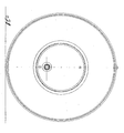
- the illustration 1 shows a frontal view of the wheel:
- the hollow cylindrical wheel with size and characteristics fit for the purpose, has a removable base Fig.2(a) and a fixed, non removable one.
- a bearing is fitted by friction Fig.2(b) .
- a metal plate is also fitted by friction Fig.2(c) . This plate does not exceed the inner ring of the bearing and it is fixed externally to a fixed point with two cylinders Fig.2(i) .
- this axis has a crank Fig.2(f) with suitable radius connected to a connecting rod Fig.2(g) of suitable length that with the other end connects to a fixed axis Fig.2(h) placed in the centre of the lateral surface of the wheel, corresponding to the maximum distance from the centre of the axis e.
- the active force A (weight of the wheel + possible added mass) for the rotation of the wheel has its application point on the crank button.
- the resistant force R produced by the operation of the energy generating machine to which the eccentric axis is connected, has its application point also on the crank button but with opposite direction.
Landscapes
- Engineering & Computer Science (AREA)
- Chemical & Material Sciences (AREA)
- Combustion & Propulsion (AREA)
- Mechanical Engineering (AREA)
- General Engineering & Computer Science (AREA)
- Connection Of Motors, Electrical Generators, Mechanical Devices, And The Like (AREA)
- Air Bags (AREA)
Abstract
The "Energy Generating Wheel" due to the disposition of its components (rotating axis in eccentric position connected to it), by rotating, uses its own weight-force and that of what is loaded onto it.
The resulting force, with application point on the crank button, increases the kinetic energy of the eccentric shaft and therefore of the machine connected to it.
In the industrial field we expect to apply it mainly to electric cars.
The "Energy Generating Wheel" would considerably increase the performance of electric cars and also it expects:
1) unlimited autonomy
2) pollution free emissions
1) unlimited autonomy
2) pollution free emissions
Description
- by Argentino Emilio resident in Cerignola (FG) via Aldo Moro n.21, with Italian Nationality.
Registered on under n - This industrial invention is a hollow cylindrical wheel or with a different shape (for ex. disc, etc...) with rotating axis connected to it, in eccentric position with respect to its centre of rotation
Fig.1-Fig.2 . - By making the wheel spin with the right connection, its weight-force is discharged onto the eccentric axis increasing the kinetic energy of the latter thus increasing its performance.
- By connecting this axis directly or indirectly to an energy generating machine or becoming itself axis of a machine (for ex. bicycle, velocipede, etc), its efficiency increases in proportion to the weight-force of the wheel plus that of the mass loaded onto it.
- To conclude, by using the weight-force, the "Energy Generating Wheel" generates kinetic energy that can then be converted into another form of energy.
- In modem technology there is no similar device thus it is not possible to compare it with other devices to find possible advantages or disadvantages. The invention will now be described and illustrated with reference to the attached drawings that show a simplified form of execution of the "Energy Generating Wheel" according to the invention.
- The
illustration 1 shows a frontal view of the wheel: - The illustration 2 shows the section according to a vertical plane parallel to the eccentric axis.
- The hollow cylindrical wheel, with size and characteristics fit for the purpose, has a removable base
Fig.2(a) and a fixed, non removable one. - They both have a hole at the centre with diameter that is about half the diameter of the wheel.
- In each hole a bearing is fitted by friction
Fig.2(b) . At the centre of the bearing a metal plate is also fitted by frictionFig.2(c) . This plate does not exceed the inner ring of the bearing and it is fixed externally to a fixed point with two cylindersFig.2(i) . - Inside it, at about 20mm from the centre of rotation of the wheel, there is a hole with diameter suitable to hold a bearing
Fig.2(d) with internal diameter suitable to enable the passage of the eccentric axisFig.2(e) . - In its central part this axis has a crank
Fig.2(f) with suitable radius connected to a connecting rodFig.2(g) of suitable length that with the other end connects to a fixed axisFig.2(h) placed in the centre of the lateral surface of the wheel, corresponding to the maximum distance from the centre of the axis e. - By rotating in clockwise and anti-clockwise direction, thanks to the position of the bearings and through the connecting rod-crank system, transmits the movement of the eccentric axis that will rotate in the same direction accomplishing two spins for each wheel revolution.
- The active force A (weight of the wheel + possible added mass) for the rotation of the wheel has its application point on the crank button.
- The resistant force R, produced by the operation of the energy generating machine to which the eccentric axis is connected, has its application point also on the crank button but with opposite direction.
- Due to the action of the force A, at an increase of the resistance R, the wheel tends to rotate by pivoting on the crank button and loading onto it all its weight-force. It exceeds R thus increasing the kinetic energy of the machine and therefore the quantity of work produced.
- Practically speaking, the execution details may however vary without leaving the invention ambit and thus the domain invention patent.
Claims (4)
- The rotating cylindrical metal hollow wheel Fig.1-2 has a rotation axis or semiaxis Fig. 2(e) in an eccentric position with respect to the rotating wheel center.
- According to the previous claim, the wheel has an eccentric axis Fig.2(e) linked through a crank-connecting rod Fig.2(f-g) to the wheel Fig.2(h) and driven by it.
- According to the previous claims, the wheel has a metal plate Fig.2(c) in the centre of the bearing Fig.2(b), that contains the bearing Fig.2(d) and the fixing pins Fig.2(i).
- According to the previous claims, thanks to the position of the bearings Fig.2(b-d), the crank-connecting rod system Fig.2(f-g) and the eccentric position of the rotation axis Fig.2(e), the wheel allows the axis to rotate in the same direction accomplishing two spins for each wheel revolution.
All aboave has been described and illustrated for the specified aims.
Applications Claiming Priority (1)
| Application Number | Priority Date | Filing Date | Title |
|---|---|---|---|
| IT000001A ITFG20100001A1 (en) | 2010-02-02 | 2010-02-02 | ENERGY WHEEL |
Publications (1)
| Publication Number | Publication Date |
|---|---|
| EP2366900A2 true EP2366900A2 (en) | 2011-09-21 |
Family
ID=43733574
Family Applications (1)
| Application Number | Title | Priority Date | Filing Date |
|---|---|---|---|
| EP11425003A Withdrawn EP2366900A2 (en) | 2010-02-02 | 2011-01-12 | Energy generating wheel |
Country Status (2)
| Country | Link |
|---|---|
| EP (1) | EP2366900A2 (en) |
| IT (1) | ITFG20100001A1 (en) |
Cited By (2)
| Publication number | Priority date | Publication date | Assignee | Title |
|---|---|---|---|---|
| WO2018141039A1 (en) * | 2017-02-03 | 2018-08-09 | LIMA FERNANDES, Divino | Integrated kinetic energy conversion system |
| WO2020041844A1 (en) * | 2018-08-30 | 2020-03-05 | Predict Consultoria Tecnologia Ltda | Torque multiplier and electrical generator comprising said torque multiplier associated with an oscillating mass with a variable centre of gravity |
Family Cites Families (3)
| Publication number | Priority date | Publication date | Assignee | Title |
|---|---|---|---|---|
| US20080011552A1 (en) * | 2006-03-31 | 2008-01-17 | Stephen Raoul La Perle | Gravity powered rotational machine and method |
| AU2008200525B2 (en) * | 2007-10-05 | 2010-03-11 | Carl James Luttmer | A stand alone flywheel engine |
| FR2923273A1 (en) * | 2007-11-02 | 2009-05-08 | Abdelhafid Berchid | Rotative mechanical energy creating device i.e. motor, for vehicle, has circular plates connected by axle that is separated into central male and female sockets, and central spring fixed to male and female sockets |
-
2010
- 2010-02-02 IT IT000001A patent/ITFG20100001A1/en unknown
-
2011
- 2011-01-12 EP EP11425003A patent/EP2366900A2/en not_active Withdrawn
Non-Patent Citations (1)
| Title |
|---|
| None |
Cited By (4)
| Publication number | Priority date | Publication date | Assignee | Title |
|---|---|---|---|---|
| WO2018141039A1 (en) * | 2017-02-03 | 2018-08-09 | LIMA FERNANDES, Divino | Integrated kinetic energy conversion system |
| WO2020041844A1 (en) * | 2018-08-30 | 2020-03-05 | Predict Consultoria Tecnologia Ltda | Torque multiplier and electrical generator comprising said torque multiplier associated with an oscillating mass with a variable centre of gravity |
| CN112997004A (en) * | 2018-08-30 | 2021-06-18 | 预测咨询技术有限公司 | Torque multiplier associated with an oscillating mass with variable center of gravity and generator comprising said torque multiplier |
| GB2591923A (en) * | 2018-08-30 | 2021-08-11 | Predict Consultoria Tecnologia Ltda | Torque multiplier and electrical generator comprising said torque multiplier associated with an oscillating mass with a variable centre of gravity |
Also Published As
| Publication number | Publication date |
|---|---|
| ITFG20100001A1 (en) | 2010-05-04 |
Similar Documents
| Publication | Publication Date | Title |
|---|---|---|
| US6694844B2 (en) | Apparatus to recover energy through gravitational force | |
| CN105945690B (en) | A circular revolution grinding device | |
| JP2009216017A5 (en) | ||
| JP2014040902A5 (en) | ||
| CN103259453A (en) | Piezoelectric cantilever beam generator for wind driven generator blade monitoring system | |
| EP2366900A2 (en) | Energy generating wheel | |
| CN101984270A (en) | Engine balancer | |
| CN202507170U (en) | Workpiece shaft for grinding machine | |
| US20110226555A1 (en) | Wheel arm displacing center of gravity | |
| RU2515336C2 (en) | Single-shaft planetary directed vibration actuator | |
| RU2006124279A (en) | MATERIAL GRINDER HAMMER ROTOR | |
| CN214281073U (en) | Small-size electric motor rotor and motor | |
| CN108731861B (en) | Centrifugal force constant torque output device | |
| RU134714U1 (en) | MOTOR-Flywheel | |
| RU165866U1 (en) | CRANKS-STAINLESS MECHANISM | |
| RU126391U1 (en) | TORQUE STRENGTH MECHANISM | |
| RU118709U1 (en) | ROTATION TOTAL SUMMER | |
| CN208060056U (en) | Chassis dynamometer main shaft support device | |
| KR20100020732A (en) | A power machine for using centrifugal force | |
| WO2010066068A1 (en) | A power output device and a power output strengthening mechanism | |
| WO2015101815A1 (en) | Connecting rod/crank transmission system and crankshaft | |
| KR20220134794A (en) | a rotating device driven by the flywheel principle | |
| JP3001324U (en) | Pachinko launcher structure | |
| TWM567309U (en) | Superimposition type dynamic unbalanced power generation device | |
| EP1733957A3 (en) | Roller brake mounting adapter |
Legal Events
| Date | Code | Title | Description |
|---|---|---|---|
| PUAI | Public reference made under article 153(3) epc to a published international application that has entered the european phase |
Free format text: ORIGINAL CODE: 0009012 |
|
| AK | Designated contracting states |
Kind code of ref document: A2 Designated state(s): AL AT BE BG CH CY CZ DE DK EE ES FI FR GB GR HR HU IE IS IT LI LT LU LV MC MK MT NL NO PL PT RO RS SE SI SK SM TR |
|
| AX | Request for extension of the european patent |
Extension state: BA ME |
|
| STAA | Information on the status of an ep patent application or granted ep patent |
Free format text: STATUS: THE APPLICATION IS DEEMED TO BE WITHDRAWN |
|
| 18D | Application deemed to be withdrawn |
Effective date: 20130801 |