EP2366627A1 - Propellant tank and vapor jet emitting device including same - Google Patents
Propellant tank and vapor jet emitting device including same Download PDFInfo
- Publication number
- EP2366627A1 EP2366627A1 EP11156836A EP11156836A EP2366627A1 EP 2366627 A1 EP2366627 A1 EP 2366627A1 EP 11156836 A EP11156836 A EP 11156836A EP 11156836 A EP11156836 A EP 11156836A EP 2366627 A1 EP2366627 A1 EP 2366627A1
- Authority
- EP
- European Patent Office
- Prior art keywords
- propellant
- storing area
- tank body
- liquid
- gas
- Prior art date
- Legal status (The legal status is an assumption and is not a legal conclusion. Google has not performed a legal analysis and makes no representation as to the accuracy of the status listed.)
- Granted
Links
Images


Classifications
-
- F—MECHANICAL ENGINEERING; LIGHTING; HEATING; WEAPONS; BLASTING
- F02—COMBUSTION ENGINES; HOT-GAS OR COMBUSTION-PRODUCT ENGINE PLANTS
- F02K—JET-PROPULSION PLANTS
- F02K9/00—Rocket-engine plants, i.e. plants carrying both fuel and oxidant therefor; Control thereof
- F02K9/42—Rocket-engine plants, i.e. plants carrying both fuel and oxidant therefor; Control thereof using liquid or gaseous propellants
-
- B—PERFORMING OPERATIONS; TRANSPORTING
- B64—AIRCRAFT; AVIATION; COSMONAUTICS
- B64G—COSMONAUTICS; VEHICLES OR EQUIPMENT THEREFOR
- B64G1/00—Cosmonautic vehicles
- B64G1/22—Parts of, or equipment specially adapted for fitting in or to, cosmonautic vehicles
- B64G1/40—Arrangements or adaptations of propulsion systems
- B64G1/402—Propellant tanks; Feeding propellants
- B64G1/4021—Tank construction; Details thereof
-
- F—MECHANICAL ENGINEERING; LIGHTING; HEATING; WEAPONS; BLASTING
- F02—COMBUSTION ENGINES; HOT-GAS OR COMBUSTION-PRODUCT ENGINE PLANTS
- F02K—JET-PROPULSION PLANTS
- F02K9/00—Rocket-engine plants, i.e. plants carrying both fuel and oxidant therefor; Control thereof
- F02K9/42—Rocket-engine plants, i.e. plants carrying both fuel and oxidant therefor; Control thereof using liquid or gaseous propellants
- F02K9/60—Constructional parts; Details not otherwise provided for
- F02K9/605—Reservoirs
Definitions
- the aforementioned prior-art propellant tank requires that heat be transferred to the whole mass of the foamed metal by heating with the heater in order to cause evaporation of part of the propellant, and thus, requires a much greater amount of external thermal energy than otherwise.
- the propellant tank further comprises a propellant holding member arranged in the liquid propellant storing area of the tank body, adjacent to the mesh member, to hold the liquid propellant in pores thereof.
- the propellant tank or the vapor jet emitting device according to the present invention can be mounted on spin-stabilized satellites and 3-axis stabilized satellites placed in the microgravity environment.
- the propellant tank 2 includes a cylindrical tank body 21 for storing a liquid propellant A.
- the tank body 21 is made of aluminum and has an axis L to be aligned with a spin axis of the spin-stabilized satellite.
- the tank body has a gas outlet 21D at the top and a propellant inlet 21F at the bottom, each located on the axis L.
- the terms "top” and “bottom” are used with respect to the propellant tank shown in FIG. 1 .
- the spin-stabilized satellite is launched with the propellant tank arranged with this top side up.
- a lower limit to which the pressure in the gas storing area GA is allowed to decrease by vapor discharge through the gas outlet 21D is set on the basis of pressure values allowing the liquid film of the liquid propellant to be maintained on the mesh member 23 (break pressure on the mesh member 23). Specifically, the lower limit to which the pressure is allowed to decrease by the pulse being “on” is set above the break pressure.
- the foamed metal 25 is arranged adjacent to the mesh member 23, which reduces sloshing of the liquid propellant A and improves heat transfer to the propellant A.
Landscapes
- Engineering & Computer Science (AREA)
- Chemical & Material Sciences (AREA)
- Combustion & Propulsion (AREA)
- Mechanical Engineering (AREA)
- General Engineering & Computer Science (AREA)
- Remote Sensing (AREA)
- Aviation & Aerospace Engineering (AREA)
- Filling Or Discharging Of Gas Storage Vessels (AREA)
Abstract
Description
- This invention relates to a propellant tank mounted on, for example a spacecraft such as an artificial satellite to store a liquid propellant and supply vapor produced by evaporation of part of the liquid propellant to an external location, and a vapor jet emitting device for producing thrust by emitting a jet of the vapor supplied from the propellant tank.
- A propellant tank of this type constituting the prior art is disclosed in Japanese Patent Application Preliminary Publication No.
2009-214695 - The propellant tank disclosed therein comprises a tank body for storing a liquid propellant, foamed metal filling approximately the whole interior of the tank body, and a heater surrounding the tank body. The tank body has a gas outlet. The tank body stores the liquid propellant in a state that the liquid propellant is held in pores of the foamed metal.
- This propellant tank is designed to cause evaporation of part of the propellant in the tank body by heating with the heater. A vapor jet emitting device including this propellant tank is designed to supply vapor produced inside the tank body, to a thruster connected to the gas outlet so that the thruster can produce thrust by emitting a vapor jet.
- The aforementioned prior-art propellant tank with weighty foamed metal filling approximately the whole interior of the tank body can store the liquid propellant in a state that it is held in pores of the foamed metal, but cannot be lightweight.
- Further, the aforementioned prior-art propellant tank requires that heat be transferred to the whole mass of the foamed metal by heating with the heater in order to cause evaporation of part of the propellant, and thus, requires a much greater amount of external thermal energy than otherwise. These are the problems with the prior art to which a solution is sought.
- The present invention has been made in consideration of the above problems. An object of the present invention is to provide a propellant tank which is lightweight and capable of supplying only vapor produced by evaporation of a propellant to an external location, and requires a smaller amount of external thermal energy, and a vapor jet emitting device including such propellant tank.
- The present invention provides a propellant tank for storing a liquid propellant and supplying vapor produced by evaporation of part of the liquid propellant to an external location, characterized by comprising a tank body for storing the liquid propellant, and a mesh member arranged inside the tank body to cover a liquid surface of the liquid propellant to divide an interior of the tank body into a liquid propellant storing area and a gas storing area by utilizing surface tension of the liquid propellant, the gas storing area of the tank body being kept at higher temperature than temperature in the liquid propellant storing area, and the tank body having a propellant inlet opening into the liquid propellant storing area and a gas outlet opening into the gas storing area.
- The features of the present invention described above provide an excellent effect that the propellant tank can be lightweight and supply only vapor produced by evaporation of the propellant to an external location, and requires a smaller amount of external thermal energy to cause evaporation of the propellant.
- Preferably, the propellant tank further comprises a heating means such as a heater arranged to a gas storing area side of the tank body to keep the gas storing area at higher temperature than the temperature in the liquid propellant storing area. In particular the heating means is arranged adjacent to the gas storing area side of the tank body. In particular the heater is arranged outside of the tank body.
- Such heating means provides an excellent effect that the gas storing area of the tank body is reliably kept at higher temperature than the temperature in the liquid propellant storing area, and thus, reversal of the liquid propellant storing area and the gas storing area is reliably prevented.
- Preferably, the propellant tank further comprises a propellant holding member arranged in the liquid propellant storing area of the tank body, adjacent to the mesh member, to hold the liquid propellant in pores thereof.
- Such propellant holding member provides an excellent effect that sloshing of the liquid propellant is reduced and heat transfer to the propellant is improved.
- Preferably, the propellant tank further comprises a liquid droplet retaining member arranged in the gas storing area of the tank body to cause droplets of the liquid propellant floating in the gas storing area to adhere thereto.
- Such liquid droplet retaining member provides an excellent effect that, if droplets of the liquid propellant enter and float in the gas storing area, they are reliably caught and retained on the liquid droplet retaining member.
- The present invention also provides a vapor jet emitting device for producing thrust by emitting a jet of vapor produced from a liquid propellant, characterized by comprising a propellant tank of the type described above for storing the liquid propellant, and a thruster connected to the gas outlet of the tank body of the propellant tank by a gas supply line to emit a jet of vapor produced inside the tank body and supplied through the gas outlet, the gas supply line between the tank body and the thruster being kept at higher temperature than temperature inside the tank body to prevent liquefaction of vapor in the gas supply line.
- The features of the present invention described above provide an excellent effect that the vapor jet emitting device can be a lightweight and simple system as a whole.
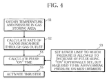
- Preferably, the vapor jet emitting device further comprises a control section for obtaining temperature and pressure in the gas storing area of the tank body, setting a lower limit to which the pressure in the gas storing area is allowed to decrease by vapor discharge through the gas outlet, on the basis of a minimum pressure value allowing a liquid film of the liquid propellant to be maintained on the mesh member, calculating "on" time for a pulse causing vapor discharge through the gas outlet so that the vapor discharge will not result in a pressure decrease below the lower limit, and activating the thruster by feeding a pulse with the "on" time calculated.
- Such control section provides an excellent effect that break of the liquid film on the mesh member, which results in supply of the propellant in liquid form, is prevented.
- In the propellant tank according to the present invention, the mesh member arranged inside the tank body causes the liquid propellant to form a liquid film on it by surface tension, thereby dividing the interior of the tank body into a liquid propellant storing area and a gas storing area. In addition, the gas storing area is kept at higher temperature than temperature in the liquid propellant storing area. This prevents reversal of the liquid propellant storing area and the gas storing area and establishes almost complete separation between a liquid layer and a gas layer inside the tank body, and thus, enables supply of only vapor produced by evaporation of the propellant to an external location.
- Further, the propellant tank according to the present invention, which does not require that the foamed metal fill approximately the whole interior of the tank body, can be lightweight.
- In the propellant tank according to the present invention, the tank body may be made of a material such as aluminum or SUS (stainless used steel). The mesh member may be made of a material such as SUS or titanium. The mesh size may be chosen within a range of values ensuring that the liquid propellant forms a liquid film on the mesh member by surface tension at any phase of the satellite. Here, the "mesh" refers to not only a common net structure, but also a porous structure that a sintered metal has, and a porous structure made by boring a lot of minute holes in a plate.
- The liquid propellant to be stored in the tank body of the propellant tank according to the present invention may be chosen from those which easily evaporate without heating. It may be isobutane, which is a liquefied petroleum gas, or an alternative for chlorofluorocarbon, such as HFC-134a, for example. HFC-134a is however preferable because it is nonflammable and atoxic, and does not cause corrosion of the tank body and the mesh member.
- In the propellant tank according to the present invention, in place of the heating means such as a heater, solar thermal radiation may be used to keep the gas storing area of the tank body at higher temperature than the temperature in the liquid propellant storing area.
- When the heating means such as a heater is used for this purpose, the heating means may be arranged either outside or inside the tank body. It is however preferable to arrange it outside the tank body, because in that case, the heating means dose not require insulating.
- The heating means such as a heater, provided in this manner, can keep the gas storing area of the tank body at higher temperature than the temperature in the liquid propellant storing area, thereby reliably preventing reversal of the liquid propellant storing area and the gas storing area.
- When solar thermal radiation is used for the above purpose, it is desirable to control the attitude of a spacecraft and the orientation of a reflection panel so that sunlight will desirably always impinge on the gas storing area side of the tank body.
- The use of solar thermal radiation obviates the need to mount a heating means such as a heater, resulting in a more lightweight propellant tank.
- Temperature in the gas storing area is measured with a temperature sensor provided on the gas storing area side of the tank body, while temperature in the liquid propellant storing area, or temperature of the liquid propellant is measured with a temperature sensor provided on the liquid propellant area side of the tank body. The gas supply line, or piping may be kept at higher temperature than the temperature inside the tank body by using either a heating means such as a heater or solar thermal radiation, as is the case with the tank body.
- The propellant holding member arranged in the liquid propellant storing area of the tank body of the propellant tank according to the present invention may be made of foam of a lightweight and high thermal conductive metal, such as nickel. The foamed metal arranged adjacent to the mesh member can reduce sloshing of the liquid propellant and improve heat transfer to the propellant.
- The liquid droplet retaining member arranged in the gas storing area of the propellant tank according to the present invention may be a flat plate of a lightweight metal, such as aluminum. The propellant tank according to the present invention intended to be mounted on a spin-stabilized satellite should have a plurality of such flat plates arranged around the axis of the propellant tank (spin axis) at appropriate intervals so that droplets of the liquid propellant floating in the gas storing area can be reliably caught and retained thereon.
- The propellant tank according to the present invention however does not necessarily need to have the propellant holding member or the liquid droplet retaining member.
- The vapor jet emitting device according to the present invention does not require a gas accumulator or a combustion device, and thus, can be a more lightweight and simpler system than otherwise.
- The control section in the vapor jet emitting device according to the present invention sets a lower limit to which the pressure in the gas storing area is allowed to decrease by vapor discharge through the gas outlet, calculates "on" time for a pulse causing vapor discharge through the gas outlet so that the vapor discharge will not result in a pressure decrease below the lower limit, and activates the thruster by feeding a pulse with the "on" time calculated. This ensures that only the vapor produced by evaporation of the liquid propellant is supplied from the propellant tank.
- The vapor jet emitting device according to the present invention may be arranged such that the above control is performed by the control section on the basis of manual operation.
- The propellant tank or the vapor jet emitting device according to the present invention can be mounted on spin-stabilized satellites and 3-axis stabilized satellites placed in the microgravity environment.
- The present invention will become more fully understood from the detailed description given hereinafter and the accompanying drawings which are given by way of illustration only, and thus, are not limitative of the present invention, and wherein:
-
FIG. 1 is a schematic diagram illustrating the configuration of a vapor jet emitting device including a propellant tank, according to an embodiment of the present invention; -
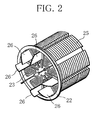
FIG. 2 is a perspective view illustrating a component to be arranged inside a tank body of the propellant tank ofFIG. 1 ; -
FIG. 3 is a graph representing relation between temperature in a gas storing area in the tank and pulse "on" time, on the basis of which control over the vapor jet emitting device ofFIG. 1 is performed; and -
FIG. 4 is a flow chart giving a summary of control over the vapor jet emitting device ofFIG. 1 . - With reference to the drawings attached, a propellant tank and a vapor jet emitting device according to the present invention will be described below.
-
FIGS. 1 to 4 show a vapor jet emitting device including a propellant tank according to an embodiment of the present invention. Here, the embodiment of the present invention will be described with an example in which a vapor jet emitting device including a propellant tank is mounted on a spin-stabilized satellite. - As seen in
FIG. 1 , a vaporjet emitting device 1 comprises a propellant tank 2, a plurality ofthrusters 3 and a control section 4 as main components. - The propellant tank 2 includes a
cylindrical tank body 21 for storing a liquid propellant A. Thetank body 21 is made of aluminum and has an axis L to be aligned with a spin axis of the spin-stabilized satellite. The tank body has agas outlet 21D at the top and apropellant inlet 21F at the bottom, each located on the axis L. The terms "top" and "bottom" are used with respect to the propellant tank shown inFIG. 1 . The spin-stabilized satellite is launched with the propellant tank arranged with this top side up. - As also seen in
FIG. 2 , the propellant tank 2 includes amesh member 23 fixed by means of asupport member 22 to cover the liquid surface of the liquid propellant A, inside thetank body 21. Themesh member 23 is made of SUS (stainless used steel) and provided to divide the interior of thetank body 21 into a liquid propellant storing area LA adjacent to thepropellant inlet 21F and a gas storing area GA adjacent to thegas outlet 21D, by utilizing surface tension of the liquid propellant. Themesh member 23 has a mesh size determined to ensure that the liquid propellant A forms a liquid film on the mesh member by surface tension, and thus, is held in the liquid propellant storing area LA, at any phase of the spin-stabilized satellite. - The propellant tank 2 further includes, as a heating means, a
heater 24 arranged outside thetank body 21, adjacent to the gas storing area GA. Theheater 24 is provided to heat the gas storing area GA to keep the gas storing area GA always at higher temperature than the temperature in the liquid propellant storing area LA, thereby preventing reversal of the gas storing area GA and the liquid propellant storing area LA. - The temperature in the gas storing area GA is measured with a
temperature sensor 8 described below, while the temperature in the liquid propellant storing area LA, or temperature of the liquid propellant A is measured with a propellant temperature sensor not shown. - The propellant tank 2 has foamed metal (propellant holding member) 25 arranged in the liquid storing area LA of the
tank body 21, adjacent to themesh member 23, to hold the liquid propellant A in its pores. - The propellant tank 2 further has a plurality of flat plates (liquid droplet retaining member) 26 to cause droplets of the liquid propellant floating in the gas storing area GA of the
tank body 21 to adhere to them. Theflat plates 26 are arranged around the axis L of thetank body 21 at intervals of 45° and fixed to asupport member 22. - In the vapor
jet emitting device 1, thethrusters 3 are connected to thegas outlet 21D of thetank body 21 of the propellant tank 2 by piping 5. On thepiping 5, or gas supply line, a liquid introduction/discharge valve 6, apressure meter 7, and a piping temperature instrument not shown are fitted. By keeping thepiping 5 always at higher temperature than the temperature in thetank body 21 with a heating means such as a heater, vapor discharged through thegas outlet 21D is prevented from becoming liquefied in thepiping 5. - The control section 4 of the vapor
jet emitting device 1 is electrically connected to the gas storingarea temperature sensor 8 fitted to thetank body 21 of the propellant tank 2, thepressure meter 7, and thethrusters 3.Reference character 9 inFIG. 1 indicates a liquid introduction/discharge valve to allow a flow to or from thepropellant inlet 21F. - In the present embodiment, the control section 4 performs control on the basis of relation between temperature in the gas storing area GA of the
tank body 21 and pulse "on" time, represented by a graph shown inFIG. 3 . - The control performed by the control section 4 is open loop control to limit the pulse "on" time on the basis of temperature and pressure in the gas storing area GA. As shown in
FIG. 4 , first at step S1, temperature and pressure in the gas storing area GA of thetank body 21 of the propellant tank 2 are obtained from thetemperature sensor 8 and thepressure meter 7. As seen inFIG. 3 , as the temperature in the gas storing area GA increases, the pressure in the gas storing area GA increases, so that vapor discharges through thegas outlet 21D at an increased rate. Thus, at step S2, the rate of vapor discharge through thegas outlet 21D is calculated from the pressure in the gas storing area GA. - When vapor discharges through the
gas outlet 21D at an increased rate, the pulse "on" time needs to be shortened. Thus, at step S3, a lower limit to which the pressure in the gas storing area GA is allowed to decrease by vapor discharge through thegas outlet 21D is set on the basis of pressure values allowing the liquid film of the liquid propellant to be maintained on the mesh member 23 (break pressure on the mesh member 23). Specifically, the lower limit to which the pressure is allowed to decrease by the pulse being "on" is set above the break pressure. - Then, at step S4, the "on" time for a pulse causing vapor discharge through the
gas outlet 21D is so calculated that the vapor discharge will not result in a pressure decrease below the lower limit, and at step S5, thethrusters 3 are activated by feeding a pulse with the "on" time calculated. - As stated above, in the propellant tank 2 according to the present embodiment, the
mesh member 23 arranged inside thetank body 21 causes the liquid propellant to form a liquid film on it by surface tension, thereby dividing the interior of thetank body 21 into a liquid propellant storing area LA and a gas storing area GA. In addition, of the two areas, only the gas storing area GA is heated with theheater 24 to ensure that it is kept at higher temperature than the temperature in the liquid propellant storing area LA. This not only establishes almost complete separation between a liquid layer and a gas layer inside thetank body 21 but also prevents reversal of the two layers, and thus, enables only the vapor produced by evaporation of the propellant A to be supplied to thethrusters 3. - Unlike the prior art, the foamed metal does not need to fill approximately the whole interior of the tank body, resulting in a great reduction in weight as compared with the prior art.
- Further, in the propellant tank 2 according to the present embodiment, the foamed
metal 25 is arranged adjacent to themesh member 23, which reduces sloshing of the liquid propellant A and improves heat transfer to the propellant A. - Further, the propellant tank 2 according to the present embodiment has, in the gas storing area GA, eight
flat plates 26 arranged around the axis L of thetank body 21 at intervals of 45°. Thus, if droplets of the liquid propellant enter and float in the gas storing area GA, the eightflat plates 26 rotating around the axis L can reliably catch and retain such liquid droplets by causing the liquid droplets to adhere to them. - The vapor
jet emitting device 1 according to the present embodiment does not require a gas accumulator or a combustion device, and thus, can be a more lightweight and simpler system than otherwise. In addition, the control section 4 controls the "on" time for a pulse causing vapor discharge to prevent discharge of liquid droplets from the propellant tank 2 through thegas outlet 21D. As a result, only the vapor produced by evaporation of the propellant A is supplied from the propellant tank 2 to thethrusters 3. - In the above, an embodiment of the present invention has been described with an example in which a vapor jet emitting device including a propellant tank is mounted on a spin-stabilized satellite. The application of the present invention is however not limited to this. A propellant tank or a vapor jet emitting device according to the present invention can be mounted on a 3-axis stabilized satellite.
- Although, in the described embodiment, a
heater 24 is arranged outside thetank body 21, adjacent to the gas storing area GA, as a heating means to keep the gas storing area GA of thetank body 21 at higher temperature than that in the propellant storing area LA, the configuration is not limited to this. For example, theheater 24 may be arranged inside thetank body 21, in the gas storing area GA, or a heating means other than theheater 24 may be used as a heat source. - Alternatively, solar thermal radiation may be used to keep the gas storing area GA at higher temperature than that in the liquid propellant storing area LA. In the use of solar thermal radiation, the attitude of a spacecraft and the orientation of a reflection panel are controlled so that sunlight will desirably always impinge on the gas storing area GA side of the
tank body 21. - Although, in the described embodiment, foamed
metal 25 as a propellant holding member and a plurality offlat plates 26 as a liquid droplet retaining member are provided inside thetank body 21, the configuration is not limited to this. Thetank body 21 does not necessarily need to have foamedmetal 25 orflat plates 26.
Claims (6)
- A propellant tank for storing a liquid propellant and supplying vapor produced by evaporation of part of the liquid propellant to an external location, characterized by comprising
a tank body (21) for storing the liquid propellant, and
a mesh member (23) arranged inside the tank body to cover a liquid surface of the liquid propellant to divide an interior of the tank body into a liquid propellant storing area and a gas storing area by utilizing surface tension of the liquid propellant,
the gas storing area of the tank body being kept at higher temperature than temperature in the liquid propellant storing area, and
the tank body having a propellant inlet (21F) opening into the liquid propellant storing area and a gas outlet (21D) opening into the gas storing area. - The propellant tank according to claim 1, characterized by further comprising a heating means (24) arranged to a gas storing area side of the tank body (21) to keep the gas storing area at higher temperature than the temperature in the liquid propellant storing area.
- The propellant tank according to claim 1 or 2, characterized by further comprising a propellant holding member (25) arranged in the liquid propellant storing area of the tank body (21), adjacent to the mesh member (23), to hold the liquid propellant in pores thereof.
- The propellant tank according to any of claims 1 to 3, characterized by further comprising a liquid droplet retaining member (26) arranged in the gas storing area of the tank body (21) to cause droplets of the liquid propellant floating in the gas storing area to adhere thereto.
- A vapor jet emitting device for producing thrust by emitting a jet of vapor produced from a liquid propellant, characterized by comprising:a propellant tank according to any of claims 1 to 4 for storing the liquid propellant, anda thruster (3) connected to the gas outlet of the tank body (21) of the propellant tank by a gas supply line to emit a jet of vapor produced inside the tank body and supplied through the gas outlet,the gas supply line between the tank body and the thruster being kept at higher temperature than temperature inside the tank body.
- The vapor jet emitting device according to claim 5, characterized by further comprising a control section (4) for obtaining temperature and pressure in the gas storing area of the tank body (21), setting a lower limit to which the pressure in the gas storing area is allowed to decrease by vapor discharge through the gas outlet, on the basis of a minimum pressure value allowing a liquid film of the liquid propellant to be maintained on the mesh member (23), calculating "on" time for a pulse causing vapor discharge through the gas outlet so that the vapor discharge will not result in a pressure decrease below the lower limit, and activating the thruster (3) by feeding a pulse with the "on" time calculated.
Applications Claiming Priority (1)
| Application Number | Priority Date | Filing Date | Title |
|---|---|---|---|
| JP2010048224A JP5509429B2 (en) | 2010-03-04 | 2010-03-04 | Propellant tank and steam injection device using the propellant tank |
Publications (2)
| Publication Number | Publication Date |
|---|---|
| EP2366627A1 true EP2366627A1 (en) | 2011-09-21 |
| EP2366627B1 EP2366627B1 (en) | 2012-11-07 |
Family
ID=43875481
Family Applications (1)
| Application Number | Title | Priority Date | Filing Date |
|---|---|---|---|
| EP11156836A Not-in-force EP2366627B1 (en) | 2010-03-04 | 2011-03-03 | Propellant tank and vapor jet emitting device including same |
Country Status (3)
| Country | Link |
|---|---|
| US (1) | US8881501B2 (en) |
| EP (1) | EP2366627B1 (en) |
| JP (1) | JP5509429B2 (en) |
Cited By (2)
| Publication number | Priority date | Publication date | Assignee | Title |
|---|---|---|---|---|
| JP2011183841A (en) * | 2010-03-04 | 2011-09-22 | Japan Aerospace Exploration Agency | Propellant tank and vapor jet emitting device using the same |
| IT201900021129A1 (en) * | 2019-11-13 | 2021-05-13 | Tech For Propulsion And Innovation S P A | POWER SUPPLY UNIT FOR PROPULSIVE SYSTEMS OPERATING IN THE ABSENCE OF GRAVITY OR MICROGRAVITY |
Families Citing this family (11)
| Publication number | Priority date | Publication date | Assignee | Title |
|---|---|---|---|---|
| JP6019123B2 (en) | 2012-08-10 | 2016-11-02 | 株式会社Ihi | Steam injection device and spacecraft |
| JP6063817B2 (en) * | 2013-05-27 | 2017-01-18 | アストリウム ゲゼルシャフト ミット ベシュレンクテル ハフツング | Tank for separating liquid in orbit |
| JP6507400B2 (en) * | 2014-05-13 | 2019-05-08 | 国立研究開発法人宇宙航空研究開発機構 | Steam injection system that enables long-time injection using multiple types of liquefied gases that are insoluble to each other as fuel |
| JP6590502B2 (en) * | 2015-03-31 | 2019-10-16 | 三菱重工業株式会社 | Propellant tank and spacecraft for spacecraft |
| US11738889B2 (en) * | 2019-03-20 | 2023-08-29 | California Institute Of Technology | Integrated satellite chassis with internal propellant tank structure |
| EP4350196A4 (en) * | 2021-06-01 | 2025-05-07 | IHI Corporation | LIQUID TANK, ROCKET AND METHOD FOR MANUFACTURING A LIQUID TANK |
| CN114109653B (en) * | 2021-11-26 | 2023-04-04 | 西安交通大学 | Screen cloth passageway formula liquid acquisition device based on storage tank strengthening rib structure |
| CN114635810B (en) * | 2022-03-28 | 2023-06-20 | 上海交通大学 | Cryogenic propellant on-orbit management device for complex overload |
| KR102671438B1 (en) * | 2022-03-31 | 2024-05-30 | 세종대학교산학협력단 | Field emission electric propulsion system for satellites using liquid metal gallium as propellant |
| CN114738218A (en) * | 2022-05-05 | 2022-07-12 | 苏州纳飞卫星动力科技有限公司 | Feeding device |
| CN115158678B (en) * | 2022-09-06 | 2022-12-27 | 北京凌空天行科技有限责任公司 | Aircraft liquid propellant storage tank |
Citations (3)
| Publication number | Priority date | Publication date | Assignee | Title |
|---|---|---|---|---|
| US3222498A (en) * | 1962-05-11 | 1965-12-07 | American Radiator & Standard | Vapor generator |
| WO2006106204A2 (en) * | 2005-04-07 | 2006-10-12 | Astrium Sas | Two-phase cold gas propulsion system and tank for such a space craft propulsion system |
| EP2101056A1 (en) * | 2008-03-10 | 2009-09-16 | Japan Aerospace Exploration Agency | Liquid-fuel storage vessell and vapor jet system using the same |
Family Cites Families (7)
| Publication number | Priority date | Publication date | Assignee | Title |
|---|---|---|---|---|
| DE1248374C2 (en) * | 1964-06-10 | 1968-03-07 | Hughes Aircraft Co | Propulsion device with a jet engine |
| US3486302A (en) * | 1968-02-26 | 1969-12-30 | Martin Marietta Corp | Zero or reduced gravity storage system for two phase fluid |
| JPS59165551U (en) * | 1983-04-20 | 1984-11-06 | 三菱電機株式会社 | Surface tension tank for satellites |
| US5427334A (en) * | 1993-09-17 | 1995-06-27 | Martin Marieta Corporation | Method for making nonmetallic pressure vessel with integral propellant management vane, and pressure vessel made by the method |
| US5901557A (en) * | 1996-10-04 | 1999-05-11 | Mcdonnell Douglas Corporation | Passive low gravity cryogenic storage vessel |
| DE102009019002B3 (en) * | 2009-04-16 | 2010-11-25 | Astrium Gmbh | Bubble trap for fuel tanks in spacecraft |
| JP5509429B2 (en) * | 2010-03-04 | 2014-06-04 | 独立行政法人 宇宙航空研究開発機構 | Propellant tank and steam injection device using the propellant tank |
-
2010
- 2010-03-04 JP JP2010048224A patent/JP5509429B2/en not_active Expired - Fee Related
-
2011
- 2011-03-03 US US13/039,915 patent/US8881501B2/en not_active Expired - Fee Related
- 2011-03-03 EP EP11156836A patent/EP2366627B1/en not_active Not-in-force
Patent Citations (4)
| Publication number | Priority date | Publication date | Assignee | Title |
|---|---|---|---|---|
| US3222498A (en) * | 1962-05-11 | 1965-12-07 | American Radiator & Standard | Vapor generator |
| WO2006106204A2 (en) * | 2005-04-07 | 2006-10-12 | Astrium Sas | Two-phase cold gas propulsion system and tank for such a space craft propulsion system |
| EP2101056A1 (en) * | 2008-03-10 | 2009-09-16 | Japan Aerospace Exploration Agency | Liquid-fuel storage vessell and vapor jet system using the same |
| JP2009214695A (en) | 2008-03-10 | 2009-09-24 | Japan Aerospace Exploration Agency | Liquid fuel storage container and vapor injection system with liquid fuel storage container |
Cited By (2)
| Publication number | Priority date | Publication date | Assignee | Title |
|---|---|---|---|---|
| JP2011183841A (en) * | 2010-03-04 | 2011-09-22 | Japan Aerospace Exploration Agency | Propellant tank and vapor jet emitting device using the same |
| IT201900021129A1 (en) * | 2019-11-13 | 2021-05-13 | Tech For Propulsion And Innovation S P A | POWER SUPPLY UNIT FOR PROPULSIVE SYSTEMS OPERATING IN THE ABSENCE OF GRAVITY OR MICROGRAVITY |
Also Published As
| Publication number | Publication date |
|---|---|
| US20110214410A1 (en) | 2011-09-08 |
| US8881501B2 (en) | 2014-11-11 |
| JP2011183841A (en) | 2011-09-22 |
| EP2366627B1 (en) | 2012-11-07 |
| JP5509429B2 (en) | 2014-06-04 |
Similar Documents
| Publication | Publication Date | Title |
|---|---|---|
| US8881501B2 (en) | Propellant tank and vapor jet emitting device including same | |
| EP2366626B1 (en) | Liquid propellant tank and vapor jet emitting device including same | |
| JP5352821B2 (en) | Liquid fuel storage container and vapor injection system using the container | |
| US6581882B2 (en) | Low-thrust cryogenic propulsion module | |
| US8281566B2 (en) | Thermally-integrated fluid storage and pressurization system | |
| US12104559B1 (en) | Vapor retention device | |
| EP3348822B1 (en) | Rocket propellant tank arrangement, rocket propulsion unit, and rocket | |
| EP3133283B1 (en) | Vapor jet system | |
| US9395048B1 (en) | Thermally protected liquid acquisition device for cryogenic fluids | |
| JP7428799B2 (en) | Cold gas thruster using solid propellant | |
| JP2017137997A (en) | Cryogenic tank and method of storing cryogenic liquids | |
| CN101596939A (en) | Containers for storage of cryogenic liquids and storable power fuels | |
| EP3260378B1 (en) | Propellant tank for spacecraft, and spacecraft | |
| Amri et al. | In orbit performance of butane propulsion system | |
| JP5144365B2 (en) | Propellant tank pressure control system | |
| US4829784A (en) | Method and system for storing inert gas for electric impulse space drives | |
| US11352150B2 (en) | Spacecraft structure configured to store frozen propellant | |
| US20220204188A1 (en) | Propulsion system for satellites | |
| Chujo et al. | Development of solid-gas equilibrium propulsion system for small spacecraft |
Legal Events
| Date | Code | Title | Description |
|---|---|---|---|
| PUAI | Public reference made under article 153(3) epc to a published international application that has entered the european phase |
Free format text: ORIGINAL CODE: 0009012 |
|
| AK | Designated contracting states |
Kind code of ref document: A1 Designated state(s): AL AT BE BG CH CY CZ DE DK EE ES FI FR GB GR HR HU IE IS IT LI LT LU LV MC MK MT NL NO PL PT RO RS SE SI SK SM TR |
|
| AX | Request for extension of the european patent |
Extension state: BA ME |
|
| 17P | Request for examination filed |
Effective date: 20120319 |
|
| RIC1 | Information provided on ipc code assigned before grant |
Ipc: B64G 1/40 20060101AFI20120413BHEP |
|
| GRAP | Despatch of communication of intention to grant a patent |
Free format text: ORIGINAL CODE: EPIDOSNIGR1 |
|
| GRAS | Grant fee paid |
Free format text: ORIGINAL CODE: EPIDOSNIGR3 |
|
| GRAA | (expected) grant |
Free format text: ORIGINAL CODE: 0009210 |
|
| AK | Designated contracting states |
Kind code of ref document: B1 Designated state(s): AL AT BE BG CH CY CZ DE DK EE ES FI FR GB GR HR HU IE IS IT LI LT LU LV MC MK MT NL NO PL PT RO RS SE SI SK SM TR |
|
| REG | Reference to a national code |
Ref country code: GB Ref legal event code: FG4D |
|
| REG | Reference to a national code |
Ref country code: CH Ref legal event code: EP Ref country code: AT Ref legal event code: REF Ref document number: 582881 Country of ref document: AT Kind code of ref document: T Effective date: 20121115 |
|
| REG | Reference to a national code |
Ref country code: IE Ref legal event code: FG4D |
|
| REG | Reference to a national code |
Ref country code: DE Ref legal event code: R096 Ref document number: 602011000404 Country of ref document: DE Effective date: 20130103 |
|
| REG | Reference to a national code |
Ref country code: AT Ref legal event code: MK05 Ref document number: 582881 Country of ref document: AT Kind code of ref document: T Effective date: 20121107 |
|
| REG | Reference to a national code |
Ref country code: NL Ref legal event code: VDEP Effective date: 20121107 |
|
| REG | Reference to a national code |
Ref country code: LT Ref legal event code: MG4D |
|
| PG25 | Lapsed in a contracting state [announced via postgrant information from national office to epo] |
Ref country code: SE Free format text: LAPSE BECAUSE OF FAILURE TO SUBMIT A TRANSLATION OF THE DESCRIPTION OR TO PAY THE FEE WITHIN THE PRESCRIBED TIME-LIMIT Effective date: 20121107 Ref country code: HR Free format text: LAPSE BECAUSE OF FAILURE TO SUBMIT A TRANSLATION OF THE DESCRIPTION OR TO PAY THE FEE WITHIN THE PRESCRIBED TIME-LIMIT Effective date: 20121107 Ref country code: FI Free format text: LAPSE BECAUSE OF FAILURE TO SUBMIT A TRANSLATION OF THE DESCRIPTION OR TO PAY THE FEE WITHIN THE PRESCRIBED TIME-LIMIT Effective date: 20121107 Ref country code: NO Free format text: LAPSE BECAUSE OF FAILURE TO SUBMIT A TRANSLATION OF THE DESCRIPTION OR TO PAY THE FEE WITHIN THE PRESCRIBED TIME-LIMIT Effective date: 20130207 Ref country code: LT Free format text: LAPSE BECAUSE OF FAILURE TO SUBMIT A TRANSLATION OF THE DESCRIPTION OR TO PAY THE FEE WITHIN THE PRESCRIBED TIME-LIMIT Effective date: 20121107 Ref country code: NL Free format text: LAPSE BECAUSE OF FAILURE TO SUBMIT A TRANSLATION OF THE DESCRIPTION OR TO PAY THE FEE WITHIN THE PRESCRIBED TIME-LIMIT Effective date: 20121107 Ref country code: IS Free format text: LAPSE BECAUSE OF FAILURE TO SUBMIT A TRANSLATION OF THE DESCRIPTION OR TO PAY THE FEE WITHIN THE PRESCRIBED TIME-LIMIT Effective date: 20130307 |
|
| PG25 | Lapsed in a contracting state [announced via postgrant information from national office to epo] |
Ref country code: SI Free format text: LAPSE BECAUSE OF FAILURE TO SUBMIT A TRANSLATION OF THE DESCRIPTION OR TO PAY THE FEE WITHIN THE PRESCRIBED TIME-LIMIT Effective date: 20121107 Ref country code: GR Free format text: LAPSE BECAUSE OF FAILURE TO SUBMIT A TRANSLATION OF THE DESCRIPTION OR TO PAY THE FEE WITHIN THE PRESCRIBED TIME-LIMIT Effective date: 20130208 Ref country code: PL Free format text: LAPSE BECAUSE OF FAILURE TO SUBMIT A TRANSLATION OF THE DESCRIPTION OR TO PAY THE FEE WITHIN THE PRESCRIBED TIME-LIMIT Effective date: 20121107 Ref country code: PT Free format text: LAPSE BECAUSE OF FAILURE TO SUBMIT A TRANSLATION OF THE DESCRIPTION OR TO PAY THE FEE WITHIN THE PRESCRIBED TIME-LIMIT Effective date: 20130307 Ref country code: LV Free format text: LAPSE BECAUSE OF FAILURE TO SUBMIT A TRANSLATION OF THE DESCRIPTION OR TO PAY THE FEE WITHIN THE PRESCRIBED TIME-LIMIT Effective date: 20121107 Ref country code: BE Free format text: LAPSE BECAUSE OF FAILURE TO SUBMIT A TRANSLATION OF THE DESCRIPTION OR TO PAY THE FEE WITHIN THE PRESCRIBED TIME-LIMIT Effective date: 20121107 |
|
| PG25 | Lapsed in a contracting state [announced via postgrant information from national office to epo] |
Ref country code: AT Free format text: LAPSE BECAUSE OF FAILURE TO SUBMIT A TRANSLATION OF THE DESCRIPTION OR TO PAY THE FEE WITHIN THE PRESCRIBED TIME-LIMIT Effective date: 20121107 |
|
| PG25 | Lapsed in a contracting state [announced via postgrant information from national office to epo] |
Ref country code: CZ Free format text: LAPSE BECAUSE OF FAILURE TO SUBMIT A TRANSLATION OF THE DESCRIPTION OR TO PAY THE FEE WITHIN THE PRESCRIBED TIME-LIMIT Effective date: 20121107 Ref country code: RS Free format text: LAPSE BECAUSE OF FAILURE TO SUBMIT A TRANSLATION OF THE DESCRIPTION OR TO PAY THE FEE WITHIN THE PRESCRIBED TIME-LIMIT Effective date: 20121107 Ref country code: EE Free format text: LAPSE BECAUSE OF FAILURE TO SUBMIT A TRANSLATION OF THE DESCRIPTION OR TO PAY THE FEE WITHIN THE PRESCRIBED TIME-LIMIT Effective date: 20121107 Ref country code: BG Free format text: LAPSE BECAUSE OF FAILURE TO SUBMIT A TRANSLATION OF THE DESCRIPTION OR TO PAY THE FEE WITHIN THE PRESCRIBED TIME-LIMIT Effective date: 20130207 Ref country code: DK Free format text: LAPSE BECAUSE OF FAILURE TO SUBMIT A TRANSLATION OF THE DESCRIPTION OR TO PAY THE FEE WITHIN THE PRESCRIBED TIME-LIMIT Effective date: 20121107 Ref country code: SK Free format text: LAPSE BECAUSE OF FAILURE TO SUBMIT A TRANSLATION OF THE DESCRIPTION OR TO PAY THE FEE WITHIN THE PRESCRIBED TIME-LIMIT Effective date: 20121107 |
|
| PG25 | Lapsed in a contracting state [announced via postgrant information from national office to epo] |
Ref country code: RO Free format text: LAPSE BECAUSE OF FAILURE TO SUBMIT A TRANSLATION OF THE DESCRIPTION OR TO PAY THE FEE WITHIN THE PRESCRIBED TIME-LIMIT Effective date: 20121107 |
|
| PLBE | No opposition filed within time limit |
Free format text: ORIGINAL CODE: 0009261 |
|
| STAA | Information on the status of an ep patent application or granted ep patent |
Free format text: STATUS: NO OPPOSITION FILED WITHIN TIME LIMIT |
|
| 26N | No opposition filed |
Effective date: 20130808 |
|
| PG25 | Lapsed in a contracting state [announced via postgrant information from national office to epo] |
Ref country code: MC Free format text: LAPSE BECAUSE OF NON-PAYMENT OF DUE FEES Effective date: 20130331 Ref country code: ES Free format text: LAPSE BECAUSE OF FAILURE TO SUBMIT A TRANSLATION OF THE DESCRIPTION OR TO PAY THE FEE WITHIN THE PRESCRIBED TIME-LIMIT Effective date: 20130218 |
|
| PG25 | Lapsed in a contracting state [announced via postgrant information from national office to epo] |
Ref country code: CY Free format text: LAPSE BECAUSE OF FAILURE TO SUBMIT A TRANSLATION OF THE DESCRIPTION OR TO PAY THE FEE WITHIN THE PRESCRIBED TIME-LIMIT Effective date: 20121107 |
|
| REG | Reference to a national code |
Ref country code: DE Ref legal event code: R097 Ref document number: 602011000404 Country of ref document: DE Effective date: 20130808 |
|
| REG | Reference to a national code |
Ref country code: IE Ref legal event code: MM4A |
|
| PG25 | Lapsed in a contracting state [announced via postgrant information from national office to epo] |
Ref country code: AL Free format text: LAPSE BECAUSE OF FAILURE TO SUBMIT A TRANSLATION OF THE DESCRIPTION OR TO PAY THE FEE WITHIN THE PRESCRIBED TIME-LIMIT Effective date: 20121107 Ref country code: IE Free format text: LAPSE BECAUSE OF NON-PAYMENT OF DUE FEES Effective date: 20130303 |
|
| PG25 | Lapsed in a contracting state [announced via postgrant information from national office to epo] |
Ref country code: MT Free format text: LAPSE BECAUSE OF FAILURE TO SUBMIT A TRANSLATION OF THE DESCRIPTION OR TO PAY THE FEE WITHIN THE PRESCRIBED TIME-LIMIT Effective date: 20121107 |
|
| REG | Reference to a national code |
Ref country code: CH Ref legal event code: PL |
|
| PG25 | Lapsed in a contracting state [announced via postgrant information from national office to epo] |
Ref country code: CH Free format text: LAPSE BECAUSE OF NON-PAYMENT OF DUE FEES Effective date: 20140331 Ref country code: LI Free format text: LAPSE BECAUSE OF NON-PAYMENT OF DUE FEES Effective date: 20140331 |
|
| PG25 | Lapsed in a contracting state [announced via postgrant information from national office to epo] |
Ref country code: SM Free format text: LAPSE BECAUSE OF FAILURE TO SUBMIT A TRANSLATION OF THE DESCRIPTION OR TO PAY THE FEE WITHIN THE PRESCRIBED TIME-LIMIT Effective date: 20121107 |
|
| PG25 | Lapsed in a contracting state [announced via postgrant information from national office to epo] |
Ref country code: TR Free format text: LAPSE BECAUSE OF FAILURE TO SUBMIT A TRANSLATION OF THE DESCRIPTION OR TO PAY THE FEE WITHIN THE PRESCRIBED TIME-LIMIT Effective date: 20121107 |
|
| PG25 | Lapsed in a contracting state [announced via postgrant information from national office to epo] |
Ref country code: LU Free format text: LAPSE BECAUSE OF NON-PAYMENT OF DUE FEES Effective date: 20130303 Ref country code: HU Free format text: LAPSE BECAUSE OF FAILURE TO SUBMIT A TRANSLATION OF THE DESCRIPTION OR TO PAY THE FEE WITHIN THE PRESCRIBED TIME-LIMIT; INVALID AB INITIO Effective date: 20110303 Ref country code: MK Free format text: LAPSE BECAUSE OF FAILURE TO SUBMIT A TRANSLATION OF THE DESCRIPTION OR TO PAY THE FEE WITHIN THE PRESCRIBED TIME-LIMIT Effective date: 20121107 |
|
| REG | Reference to a national code |
Ref country code: FR Ref legal event code: PLFP Year of fee payment: 6 |
|
| REG | Reference to a national code |
Ref country code: FR Ref legal event code: PLFP Year of fee payment: 7 |
|
| REG | Reference to a national code |
Ref country code: FR Ref legal event code: PLFP Year of fee payment: 8 |
|
| PGFP | Annual fee paid to national office [announced via postgrant information from national office to epo] |
Ref country code: FR Payment date: 20230322 Year of fee payment: 13 |
|
| PGFP | Annual fee paid to national office [announced via postgrant information from national office to epo] |
Ref country code: GB Payment date: 20230321 Year of fee payment: 13 Ref country code: DE Payment date: 20230321 Year of fee payment: 13 |
|
| PGFP | Annual fee paid to national office [announced via postgrant information from national office to epo] |
Ref country code: IT Payment date: 20230328 Year of fee payment: 13 |
|
| REG | Reference to a national code |
Ref country code: DE Ref legal event code: R119 Ref document number: 602011000404 Country of ref document: DE |
|
| GBPC | Gb: european patent ceased through non-payment of renewal fee |
Effective date: 20240303 |
|
| PG25 | Lapsed in a contracting state [announced via postgrant information from national office to epo] |
Ref country code: DE Free format text: LAPSE BECAUSE OF NON-PAYMENT OF DUE FEES Effective date: 20241001 |
|
| PG25 | Lapsed in a contracting state [announced via postgrant information from national office to epo] |
Ref country code: GB Free format text: LAPSE BECAUSE OF NON-PAYMENT OF DUE FEES Effective date: 20240303 |
|
| PG25 | Lapsed in a contracting state [announced via postgrant information from national office to epo] |
Ref country code: FR Free format text: LAPSE BECAUSE OF NON-PAYMENT OF DUE FEES Effective date: 20240331 |
|
| PG25 | Lapsed in a contracting state [announced via postgrant information from national office to epo] |
Ref country code: GB Free format text: LAPSE BECAUSE OF NON-PAYMENT OF DUE FEES Effective date: 20240303 Ref country code: FR Free format text: LAPSE BECAUSE OF NON-PAYMENT OF DUE FEES Effective date: 20240331 Ref country code: DE Free format text: LAPSE BECAUSE OF NON-PAYMENT OF DUE FEES Effective date: 20241001 |
|
| PG25 | Lapsed in a contracting state [announced via postgrant information from national office to epo] |
Ref country code: IT Free format text: LAPSE BECAUSE OF NON-PAYMENT OF DUE FEES Effective date: 20240303 |