EP2366577A2 - Transmission and control system for vehicles - Google Patents
Transmission and control system for vehicles Download PDFInfo
- Publication number
- EP2366577A2 EP2366577A2 EP11170374A EP11170374A EP2366577A2 EP 2366577 A2 EP2366577 A2 EP 2366577A2 EP 11170374 A EP11170374 A EP 11170374A EP 11170374 A EP11170374 A EP 11170374A EP 2366577 A2 EP2366577 A2 EP 2366577A2
- Authority
- EP
- European Patent Office
- Prior art keywords
- clutch
- pedal
- vehicle
- engine
- accelerator
- Prior art date
- Legal status (The legal status is an assumption and is not a legal conclusion. Google has not performed a legal analysis and makes no representation as to the accuracy of the status listed.)
- Withdrawn
Links
Images


Classifications
-
- B—PERFORMING OPERATIONS; TRANSPORTING
- B60—VEHICLES IN GENERAL
- B60K—ARRANGEMENT OR MOUNTING OF PROPULSION UNITS OR OF TRANSMISSIONS IN VEHICLES; ARRANGEMENT OR MOUNTING OF PLURAL DIVERSE PRIME-MOVERS IN VEHICLES; AUXILIARY DRIVES FOR VEHICLES; INSTRUMENTATION OR DASHBOARDS FOR VEHICLES; ARRANGEMENTS IN CONNECTION WITH COOLING, AIR INTAKE, GAS EXHAUST OR FUEL SUPPLY OF PROPULSION UNITS IN VEHICLES
- B60K6/00—Arrangement or mounting of plural diverse prime-movers for mutual or common propulsion, e.g. hybrid propulsion systems comprising electric motors and internal combustion engines
- B60K6/08—Prime-movers comprising combustion engines and mechanical or fluid energy storing means
- B60K6/12—Prime-movers comprising combustion engines and mechanical or fluid energy storing means by means of a chargeable fluidic accumulator
-
- B—PERFORMING OPERATIONS; TRANSPORTING
- B60—VEHICLES IN GENERAL
- B60K—ARRANGEMENT OR MOUNTING OF PROPULSION UNITS OR OF TRANSMISSIONS IN VEHICLES; ARRANGEMENT OR MOUNTING OF PLURAL DIVERSE PRIME-MOVERS IN VEHICLES; AUXILIARY DRIVES FOR VEHICLES; INSTRUMENTATION OR DASHBOARDS FOR VEHICLES; ARRANGEMENTS IN CONNECTION WITH COOLING, AIR INTAKE, GAS EXHAUST OR FUEL SUPPLY OF PROPULSION UNITS IN VEHICLES
- B60K17/00—Arrangement or mounting of transmissions in vehicles
- B60K17/04—Arrangement or mounting of transmissions in vehicles characterised by arrangement, location or kind of gearing
- B60K17/043—Transmission unit disposed in on near the vehicle wheel, or between the differential gear unit and the wheel
-
- B—PERFORMING OPERATIONS; TRANSPORTING
- B60—VEHICLES IN GENERAL
- B60K—ARRANGEMENT OR MOUNTING OF PROPULSION UNITS OR OF TRANSMISSIONS IN VEHICLES; ARRANGEMENT OR MOUNTING OF PLURAL DIVERSE PRIME-MOVERS IN VEHICLES; AUXILIARY DRIVES FOR VEHICLES; INSTRUMENTATION OR DASHBOARDS FOR VEHICLES; ARRANGEMENTS IN CONNECTION WITH COOLING, AIR INTAKE, GAS EXHAUST OR FUEL SUPPLY OF PROPULSION UNITS IN VEHICLES
- B60K6/00—Arrangement or mounting of plural diverse prime-movers for mutual or common propulsion, e.g. hybrid propulsion systems comprising electric motors and internal combustion engines
- B60K6/20—Arrangement or mounting of plural diverse prime-movers for mutual or common propulsion, e.g. hybrid propulsion systems comprising electric motors and internal combustion engines the prime-movers consisting of electric motors and internal combustion engines, e.g. HEVs
- B60K6/42—Arrangement or mounting of plural diverse prime-movers for mutual or common propulsion, e.g. hybrid propulsion systems comprising electric motors and internal combustion engines the prime-movers consisting of electric motors and internal combustion engines, e.g. HEVs characterised by the architecture of the hybrid electric vehicle
- B60K6/48—Parallel type
-
- B—PERFORMING OPERATIONS; TRANSPORTING
- B60—VEHICLES IN GENERAL
- B60L—PROPULSION OF ELECTRICALLY-PROPELLED VEHICLES; SUPPLYING ELECTRIC POWER FOR AUXILIARY EQUIPMENT OF ELECTRICALLY-PROPELLED VEHICLES; ELECTRODYNAMIC BRAKE SYSTEMS FOR VEHICLES IN GENERAL; MAGNETIC SUSPENSION OR LEVITATION FOR VEHICLES; MONITORING OPERATING VARIABLES OF ELECTRICALLY-PROPELLED VEHICLES; ELECTRIC SAFETY DEVICES FOR ELECTRICALLY-PROPELLED VEHICLES
- B60L15/00—Methods, circuits, or devices for controlling the traction-motor speed of electrically-propelled vehicles
- B60L15/20—Methods, circuits, or devices for controlling the traction-motor speed of electrically-propelled vehicles for control of the vehicle or its driving motor to achieve a desired performance, e.g. speed, torque, programmed variation of speed
- B60L15/2054—Methods, circuits, or devices for controlling the traction-motor speed of electrically-propelled vehicles for control of the vehicle or its driving motor to achieve a desired performance, e.g. speed, torque, programmed variation of speed by controlling transmissions or clutches
-
- B—PERFORMING OPERATIONS; TRANSPORTING
- B60—VEHICLES IN GENERAL
- B60W—CONJOINT CONTROL OF VEHICLE SUB-UNITS OF DIFFERENT TYPE OR DIFFERENT FUNCTION; CONTROL SYSTEMS SPECIALLY ADAPTED FOR HYBRID VEHICLES; ROAD VEHICLE DRIVE CONTROL SYSTEMS FOR PURPOSES NOT RELATED TO THE CONTROL OF A PARTICULAR SUB-UNIT
- B60W10/00—Conjoint control of vehicle sub-units of different type or different function
- B60W10/02—Conjoint control of vehicle sub-units of different type or different function including control of driveline clutches
-
- B—PERFORMING OPERATIONS; TRANSPORTING
- B60—VEHICLES IN GENERAL
- B60W—CONJOINT CONTROL OF VEHICLE SUB-UNITS OF DIFFERENT TYPE OR DIFFERENT FUNCTION; CONTROL SYSTEMS SPECIALLY ADAPTED FOR HYBRID VEHICLES; ROAD VEHICLE DRIVE CONTROL SYSTEMS FOR PURPOSES NOT RELATED TO THE CONTROL OF A PARTICULAR SUB-UNIT
- B60W10/00—Conjoint control of vehicle sub-units of different type or different function
- B60W10/04—Conjoint control of vehicle sub-units of different type or different function including control of propulsion units
- B60W10/06—Conjoint control of vehicle sub-units of different type or different function including control of propulsion units including control of combustion engines
-
- B—PERFORMING OPERATIONS; TRANSPORTING
- B60—VEHICLES IN GENERAL
- B60W—CONJOINT CONTROL OF VEHICLE SUB-UNITS OF DIFFERENT TYPE OR DIFFERENT FUNCTION; CONTROL SYSTEMS SPECIALLY ADAPTED FOR HYBRID VEHICLES; ROAD VEHICLE DRIVE CONTROL SYSTEMS FOR PURPOSES NOT RELATED TO THE CONTROL OF A PARTICULAR SUB-UNIT
- B60W30/00—Purposes of road vehicle drive control systems not related to the control of a particular sub-unit, e.g. of systems using conjoint control of vehicle sub-units
- B60W30/18—Propelling the vehicle
- B60W30/18181—Propulsion control with common controlling member for different functions
-
- B—PERFORMING OPERATIONS; TRANSPORTING
- B60—VEHICLES IN GENERAL
- B60L—PROPULSION OF ELECTRICALLY-PROPELLED VEHICLES; SUPPLYING ELECTRIC POWER FOR AUXILIARY EQUIPMENT OF ELECTRICALLY-PROPELLED VEHICLES; ELECTRODYNAMIC BRAKE SYSTEMS FOR VEHICLES IN GENERAL; MAGNETIC SUSPENSION OR LEVITATION FOR VEHICLES; MONITORING OPERATING VARIABLES OF ELECTRICALLY-PROPELLED VEHICLES; ELECTRIC SAFETY DEVICES FOR ELECTRICALLY-PROPELLED VEHICLES
- B60L2240/00—Control parameters of input or output; Target parameters
- B60L2240/40—Drive Train control parameters
- B60L2240/48—Drive Train control parameters related to transmissions
- B60L2240/486—Operating parameters
-
- B—PERFORMING OPERATIONS; TRANSPORTING
- B60—VEHICLES IN GENERAL
- B60W—CONJOINT CONTROL OF VEHICLE SUB-UNITS OF DIFFERENT TYPE OR DIFFERENT FUNCTION; CONTROL SYSTEMS SPECIALLY ADAPTED FOR HYBRID VEHICLES; ROAD VEHICLE DRIVE CONTROL SYSTEMS FOR PURPOSES NOT RELATED TO THE CONTROL OF A PARTICULAR SUB-UNIT
- B60W2540/00—Input parameters relating to occupants
- B60W2540/10—Accelerator pedal position
-
- B—PERFORMING OPERATIONS; TRANSPORTING
- B60—VEHICLES IN GENERAL
- B60W—CONJOINT CONTROL OF VEHICLE SUB-UNITS OF DIFFERENT TYPE OR DIFFERENT FUNCTION; CONTROL SYSTEMS SPECIALLY ADAPTED FOR HYBRID VEHICLES; ROAD VEHICLE DRIVE CONTROL SYSTEMS FOR PURPOSES NOT RELATED TO THE CONTROL OF A PARTICULAR SUB-UNIT
- B60W2710/00—Output or target parameters relating to a particular sub-units
- B60W2710/02—Clutches
- B60W2710/021—Clutch engagement state
-
- B—PERFORMING OPERATIONS; TRANSPORTING
- B60—VEHICLES IN GENERAL
- B60W—CONJOINT CONTROL OF VEHICLE SUB-UNITS OF DIFFERENT TYPE OR DIFFERENT FUNCTION; CONTROL SYSTEMS SPECIALLY ADAPTED FOR HYBRID VEHICLES; ROAD VEHICLE DRIVE CONTROL SYSTEMS FOR PURPOSES NOT RELATED TO THE CONTROL OF A PARTICULAR SUB-UNIT
- B60W2710/00—Output or target parameters relating to a particular sub-units
- B60W2710/06—Combustion engines, Gas turbines
- B60W2710/0644—Engine speed
-
- Y—GENERAL TAGGING OF NEW TECHNOLOGICAL DEVELOPMENTS; GENERAL TAGGING OF CROSS-SECTIONAL TECHNOLOGIES SPANNING OVER SEVERAL SECTIONS OF THE IPC; TECHNICAL SUBJECTS COVERED BY FORMER USPC CROSS-REFERENCE ART COLLECTIONS [XRACs] AND DIGESTS
- Y02—TECHNOLOGIES OR APPLICATIONS FOR MITIGATION OR ADAPTATION AGAINST CLIMATE CHANGE
- Y02T—CLIMATE CHANGE MITIGATION TECHNOLOGIES RELATED TO TRANSPORTATION
- Y02T10/00—Road transport of goods or passengers
- Y02T10/60—Other road transportation technologies with climate change mitigation effect
- Y02T10/62—Hybrid vehicles
-
- Y—GENERAL TAGGING OF NEW TECHNOLOGICAL DEVELOPMENTS; GENERAL TAGGING OF CROSS-SECTIONAL TECHNOLOGIES SPANNING OVER SEVERAL SECTIONS OF THE IPC; TECHNICAL SUBJECTS COVERED BY FORMER USPC CROSS-REFERENCE ART COLLECTIONS [XRACs] AND DIGESTS
- Y02—TECHNOLOGIES OR APPLICATIONS FOR MITIGATION OR ADAPTATION AGAINST CLIMATE CHANGE
- Y02T—CLIMATE CHANGE MITIGATION TECHNOLOGIES RELATED TO TRANSPORTATION
- Y02T10/00—Road transport of goods or passengers
- Y02T10/60—Other road transportation technologies with climate change mitigation effect
- Y02T10/64—Electric machine technologies in electromobility
-
- Y—GENERAL TAGGING OF NEW TECHNOLOGICAL DEVELOPMENTS; GENERAL TAGGING OF CROSS-SECTIONAL TECHNOLOGIES SPANNING OVER SEVERAL SECTIONS OF THE IPC; TECHNICAL SUBJECTS COVERED BY FORMER USPC CROSS-REFERENCE ART COLLECTIONS [XRACs] AND DIGESTS
- Y02—TECHNOLOGIES OR APPLICATIONS FOR MITIGATION OR ADAPTATION AGAINST CLIMATE CHANGE
- Y02T—CLIMATE CHANGE MITIGATION TECHNOLOGIES RELATED TO TRANSPORTATION
- Y02T10/00—Road transport of goods or passengers
- Y02T10/60—Other road transportation technologies with climate change mitigation effect
- Y02T10/72—Electric energy management in electromobility
Definitions
- the invention concerns a transmission system for vehicles.
- the invention concerns a transmission system for motor vehicles, for example automobiles.
- the invention can be applied to two and four-wheeled vehicles, and it is advantageous both in light vehicles like for example automobiles, and in heavy vehicles.
- the set-up is the following: the engine, through a clutch, drive a manual or automatic gearbox, which allows the transmission ratio to be varied; downstream of the gearbox there is a drive shaft and a differential gear; at the output of the differential gear there are two axles that connect the differential gear itself to the driving wheels.
- the drive shaft is not necessary, but the set-up is substantially the same and foresees, in order: engine, gearbox, differential gear (if present), and driving wheels. It follows that the driving wheels are driven by a shaft or axle that rotates at the speed set by the gearbox and possibly by the rear-axle ratio at the differential gear.
- the transmission is generally by chain or in some cases by cardan shaft, but it substantially follows the engine-gearbox-driving wheel set-up.
- the problem forming the basis of the invention is to provide a system that is simple in construction but adapted to improve efficiency, increase performance and reduce fuel-consumption of vehicles and automobiles.
- An embodiment of the invention comprises a modification of the set-up of the transmission system, with respect to the known one which is common to substantially all vehicles currently produced.
- the idea consists of decentring the point of transmission of motion to the driving wheel, or to the driving wheels if there is more than one.
- the vehicle comprises at least one driving wheel, and the transmission system comprises at least one pinion in decentred position with respect to said driving wheel, which transmits motion to a crown arranged on the inner circumference of said driving wheel.
- the system comprises a crown gear on the inner circumference of said driving wheel, and at least one motor pinion engaged on said crown gear.
- the invention can be applied to vehicles of any kind, for example bicycles, motorcycles, automobiles and light or heavy vehicles.
- each driving wheel is equipped with a crown gear on the inner diameter and with a respective actuation pinion.
- the transmission system essentially comprises a gearshift, a differential gear, two axles at the output of the differential gear; each axle is fixedly connected to a pinion engaged with the inner crown gear of a respective driving wheel.
- the invention can be applied in vehicles with four driving wheels, with a pinion-crown engagement for each wheel.
- a system for boosting and/or recovering the kinetic energy during braking, actuated by at least one of the axles comprises at least one air compressor, which accumulates compressed air in a suitable tank, and said compressed air is used to supercharge the engine.
- the recovery system comprises an alternator that supplies electrical energy to a battery; said electrical energy can be used for the on-board accessories or for traction, also having an electric motor.
- the braking system of the automobile for example with brake discs directly associated with the axles, can be associated with the axles.
- An advantage of the invention consists of the fact that the traction point is displaced from the centre of the driving wheels to the edge of the wheel itself, where the engagement between the pinion and the inner crown takes place.
- the applicant has found that such a displacement of the traction point is advantageous because it decreases the torque required for traction and it improves the efficiency of the transmission.
- Said change of the traction point increases the thrust that can be obtained for the same available power of the engine, with all the related advantages: possibility of adopting smaller and less polluting engines, for the same performance, greater possibilities of application for electric motors.
- the axles rotate at a much higher speed than in the prior art; this promotes the recovery of kinetic energy in the ways that have been described above.
- the axles of the wheels rotate at the same speed as the wheels, since they are downstream of the gearbox and of the differential gear; such a speed is generally insufficient to directly drive an air compressor or an alternator for energy recovery.
- the axles rotate at a higher speed, of the order of 5000 revs/min for an average travel speed of the vehicle, since downstream there is the gear reduction ratio between pinion and crown gear, and they can usefully actuate a supercharger and/or energy recovery system like those mentioned above.
- the advantage is that an efficient energy recovery is obtained with relatively simple interventions on the mechanics, without modifying the engine or the upstream transmission members.
- the higher speed of the axles also allows the axles themselves to be exploited more efficiently for braking.
- vehicles are known with inboard disc brakes, i.e. mounted on the axles, but such a provision has up to now proven inefficient and has not been applied widely.
- the required braking torque on the axles is smaller, due to their high speed, and therefore the braking can be more efficient and smaller and more effective brake discs and calipers can be used, for the same braking effect.
- By mounting the brake discs and relative calipers at the axles instead of inside the wheels, the non-suspended masses are reduced, to the benefit of road handling.
- a control system for motor vehicles essentially comprises a normally open clutch, which can be combined with a conventional gearshift.
- a normally closed clutch is used, which opens by acting upon the control pedal.
- the clutch stays open; by pressing the pedal a start-of-stroke sensor is activated that closes the clutch and mechanically connects the engine to the gearbox.
- a second sensor activated by the stroke of the pedal itself, allows the accelerator to be controlled. Consequently, a control system with just two pedals is obtained.
- An advantage of the system is that the normally open clutch allows the kinetic energy to be better exploited and to reduce pollution and energy consumption.
- the engine acts as a brake.
- the clutch is normally open (NO).
- Fig. 1 schematically shows a driving wheel 1 of a motor vehicle, which mounts a tyre 2 on a suitable bearing carcass.
- the wheel 1 is equipped with a crown gear 3 that extends over the entire inner circumference of the wheel 1 itself, and is engaged by a motor pinion 4.
- Said pinion 4 when in use, is set in rotation by the engine of the vehicle, through a suitable transmission comprising, for example, a clutch and a gearshift.
- the wheel 1 is supported by a central axis or hub at the point indicated with 5.
- the pinion 4 can have a diameter of about 35-40 mm. Considering that the wheel 1 has an external diameter of about 600 mm (including the tyre) and a diameter of the crown gear 3 of about 400 mm, this is equivalent to a transmission ratio of about 10:1 or 11:1. It can thus be seen that there is a high gear reduction ratio between pinion 4 and crown 3.
- Fig. 1 it can also be seen how, in the invention, the traction point is decentred, going from the axis through point 5, as occurs in the prior art, to the engagement point between pinion 4 and crown 3, which, on the other hand, is located near to the outer circumference of the wheel itself, in contact with the ground.
- the preferred positioning of the pinion is opposite the ground, at "twelve o'clock".
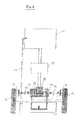
- FIG. 2 The diagram of a preferred application is shown in Fig. 2 .
- An automobile with rear wheel drive comprises an internal combustion engine 10 and a transmission system comprising a gearbox 11 and a differential gear 12.
- Said differential gear 12 has two axles 13 which actuate the driving wheels 14, right and left respectively, through a pinion-crown coupling of the type in Fig. 1 .
- each of the wheels 14 has an inner crown gear 3 engaged by a pinion 4 ( Fig. 1 ), the latter being fixedly connected to the respective axle 13.
- the aforementioned axles 13 each actuate a compressor 20, which is preferably fitted directly onto the axle.
- the compressors 20 supply compressed air to a tank 21, and the compressed air, through a line 22, is used to boost the engine 10.
- the compressors 20 can be selectively connected in the release and/or braking step, for example with an automatic clutch, so as to recover the kinetic energy of the vehicle.
- the described boosting system is more advantageous than known turbocompressors actuated by the exhaust gases, which as known suffer of delayed response and also do not allow energy recovery, but rather generally increase consumption.
- a pulley 23 is also shown, fitted onto one of the axles, which can be used to actuate an alternator and supply electrical energy to the on-board systems or to a battery pack.
- Such a system can be foreseen in combination with, or as an alternative to, the air compressors 20, and it allows further recovery of kinetic energy during braking.
- the vehicle can thus be equipped with a hybrid motorisation, which comprises the thermal engine 10 and a further electric motor (not shown); said electric motor is actuated by batteries charged through an alternator driven by the pulley 23.
- a hybrid motorisation which comprises the thermal engine 10 and a further electric motor (not shown); said electric motor is actuated by batteries charged through an alternator driven by the pulley 23.
- the axles 13 also have per se known disc brakes 24 associated with them, for the braking of the wheels 14.
- the engine 10 in the example an internal combustion engine running on petrol or diesel, drives the gearbox 11 and the differential gear 12.
- the axles 13 rotate at a speed that depends upon the operating speed of the engine and the gear engaged, but in any case higher than in conventional vehicles.
- each of the axles 13 actuates the respective wheel 14 through a pinion that engages a crown gear inside the wheel, with an analogous coupling to that between pinion 4 and crown 3 of Fig. 1 .
- the reduction ratio between axle 13 and wheel 14 is therefore of the order of 10:1 1 or even more.
- the compressors 20 feed compressed air to the tank 21, and the compressed air through the pipe 22 is used to boost the engine 10, i.e. injected into the cylinders during the intake step.
- the alternator 23 can be used to recover energy in the form of electrical energy, in particular during braking. If the vehicle is equipped with it, the electrical energy recovered during braking can then be used to feed an electric motor (hybrid drive).
- the described transmission system is not limited to use with thermal engines, but it can also be advantageously used in electric vehicles. It can also be used in motorcycles as well as in heavy vehicles, like trucks and lorries.
- the control system is based substantially upon the two pedals 113 and 114.
- the pedal 113 acts both as clutch and as accelerator.
- the clutch is opened through the effect of the springs 107 and the gearbox 101 is idle with respect to the engine 103.
- the contact A makes the valve 111 open and feeds pressurised oil generated by the pump 112 to the hydraulic cylinder 110.
- the actuation of said hydraulic cylinder 110 counteracts the thrusting of the springs 107 and automatically closes the clutch 105.
- the contact B controls the supply line 115 of the engine (e.g. flow of air and fuel), allowing the same pedal 113 to be used as accelerator.
- the pedal is released, the engine goes back to the minimum operating speed; the valve 111 closes due to the lack of the contact A, and the clutch opens placing the vehicle in idle state.
- An example of use is the following. While driving in the city centre, the engine can be kept at an operating speed of about 1000 revs/min with one gear always engaged, ideally 3rd gear. In order to set off from traffic lights, it is sufficient to press the combined pedal 113. By pressing for a few seconds and releasing, the automobile is taken to about 50-60 km/h with the engine at 1000 revs/min and in 3rd gear.
- the inventor from practical tests, has found that an automobile with medium cylinder displacement, modified according to the invention, consumes about 1.8 litres of fuel for one hour of travel in or outside of the city (100-120 km/h). Atmospheric pollution is reduced, compared to the current system, thanks to the reduced fuel consumption. The absence of continuous gearshifting also reduces sound pollution.
Landscapes
- Engineering & Computer Science (AREA)
- Chemical & Material Sciences (AREA)
- Combustion & Propulsion (AREA)
- Transportation (AREA)
- Mechanical Engineering (AREA)
- Power Engineering (AREA)
- Automation & Control Theory (AREA)
- Structure Of Transmissions (AREA)
- Control Of Transmission Device (AREA)
- Arrangement And Mounting Of Devices That Control Transmission Of Motive Force (AREA)
- Electric Propulsion And Braking For Vehicles (AREA)
- Arrangement Of Transmissions (AREA)
Abstract
Description
- The invention concerns a transmission system for vehicles. In particular, the invention concerns a transmission system for motor vehicles, for example automobiles. The invention can be applied to two and four-wheeled vehicles, and it is advantageous both in light vehicles like for example automobiles, and in heavy vehicles.
- In the prior art, the transmission system of a motor vehicle, and in particular of an automobile, always follows a predetermined set-up.
- With reference, for the sake of simplicity, to an automobile with two driving wheels and rear wheel drive, the set-up is the following: the engine, through a clutch, drive a manual or automatic gearbox, which allows the transmission ratio to be varied; downstream of the gearbox there is a drive shaft and a differential gear; at the output of the differential gear there are two axles that connect the differential gear itself to the driving wheels. In front wheel drive vehicles the drive shaft is not necessary, but the set-up is substantially the same and foresees, in order: engine, gearbox, differential gear (if present), and driving wheels. It follows that the driving wheels are driven by a shaft or axle that rotates at the speed set by the gearbox and possibly by the rear-axle ratio at the differential gear.
- In motorcycles the transmission is generally by chain or in some cases by cardan shaft, but it substantially follows the engine-gearbox-driving wheel set-up.
- There is ever-increasing interest in trying to improve efficiency and particularly to reduce the fuel consumption of automobiles, both due to the known problems of pollution, and due to the high cost of fuel.
- In recent years, various and numerous technical solutions have been proposed for this purpose, including boosting with a turbocompressor, especially for diesel engines, the adoption of increasingly complex power supply systems and, more recently, making hybrid vehicles moved by a thermal engine and by an electric motor, or else hydrogen-powered vehicles. Such solutions, however, are not entirely satisfactory particularly because they always involve greater cost and complication. Moreover, they have proven to only be applicable to certain types of vehicles, like for example medium-high class vehicles, whereas they are absolutely not applicable, for example, to commercial and/or heavy vehicles.
- There are also vehicles moved just by an electric motor, but they are not widely used due to the limited autonomy and performance, and the costs that are too high.
- With regard to the transmission, there is increasing use of automatic gearboxes. It is known that conventional automatic gearboxes, with torque converter, reduce efficiency and bring about a certain increase in consumption; consequently, there is increasing use of semiautomatic and continuously variable transmissions, which are however quite expensive and generally do not improve fuel consumption, apart from to a negligible extent, with respect to a manual gearbox. All transmission systems, both manual and automatic, still remain to the set-up that has been described above.
- The problem forming the basis of the invention is to provide a system that is simple in construction but adapted to improve efficiency, increase performance and reduce fuel-consumption of vehicles and automobiles.
- The problem is solved with a control system for vehicles and a transmission system according to the claims.
- An embodiment of the invention comprises a modification of the set-up of the transmission system, with respect to the known one which is common to substantially all vehicles currently produced. The idea consists of decentring the point of transmission of motion to the driving wheel, or to the driving wheels if there is more than one.
- The vehicle comprises at least one driving wheel, and the transmission system comprises at least one pinion in decentred position with respect to said driving wheel, which transmits motion to a crown arranged on the inner circumference of said driving wheel.
- In a preferred aspect of the invention, the system comprises a crown gear on the inner circumference of said driving wheel, and at least one motor pinion engaged on said crown gear.
- The invention can be applied to vehicles of any kind, for example bicycles, motorcycles, automobiles and light or heavy vehicles. In vehicles having a plurality of driving wheels, each driving wheel is equipped with a crown gear on the inner diameter and with a respective actuation pinion.
- In a preferred application to an automobile with two driving wheels, the transmission system according to the invention essentially comprises a gearshift, a differential gear, two axles at the output of the differential gear; each axle is fixedly connected to a pinion engaged with the inner crown gear of a respective driving wheel. Similarly, the invention can be applied in vehicles with four driving wheels, with a pinion-crown engagement for each wheel.
- According to a further aspect of the invention, it is provided a system for boosting and/or recovering the kinetic energy during braking, actuated by at least one of the axles. In a preferred embodiment, said system comprises at least one air compressor, which accumulates compressed air in a suitable tank, and said compressed air is used to supercharge the engine. In another embodiment, the recovery system comprises an alternator that supplies electrical energy to a battery; said electrical energy can be used for the on-board accessories or for traction, also having an electric motor.
- According to a further aspect of the invention, the braking system of the automobile, for example with brake discs directly associated with the axles, can be associated with the axles.
- An advantage of the invention consists of the fact that the traction point is displaced from the centre of the driving wheels to the edge of the wheel itself, where the engagement between the pinion and the inner crown takes place. The applicant has found that such a displacement of the traction point is advantageous because it decreases the torque required for traction and it improves the efficiency of the transmission. Said change of the traction point increases the thrust that can be obtained for the same available power of the engine, with all the related advantages: possibility of adopting smaller and less polluting engines, for the same performance, greater possibilities of application for electric motors.
- Another advantage is given by the fact that between the pinion and the crown inside the driving wheel there is a high reduction ratio, typically at least 10:1. It follows from this that simpler and less expensive gearshifts can be used, with 3 or 4 speeds only instead of the 5-6 speeds of current gearboxes.
- Moreover, due to said reduction ratio, the axles rotate at a much higher speed than in the prior art; this promotes the recovery of kinetic energy in the ways that have been described above. In particular, in the prior art the axles of the wheels rotate at the same speed as the wheels, since they are downstream of the gearbox and of the differential gear; such a speed is generally insufficient to directly drive an air compressor or an alternator for energy recovery. Thanks to the invention, however, the axles rotate at a higher speed, of the order of 5000 revs/min for an average travel speed of the vehicle, since downstream there is the gear reduction ratio between pinion and crown gear, and they can usefully actuate a supercharger and/or energy recovery system like those mentioned above. The advantage is that an efficient energy recovery is obtained with relatively simple interventions on the mechanics, without modifying the engine or the upstream transmission members.
- The higher speed of the axles also allows the axles themselves to be exploited more efficiently for braking. Indeed, vehicles are known with inboard disc brakes, i.e. mounted on the axles, but such a provision has up to now proven inefficient and has not been applied widely. Thanks to the invention, the required braking torque on the axles is smaller, due to their high speed, and therefore the braking can be more efficient and smaller and more effective brake discs and calipers can be used, for the same braking effect. By mounting the brake discs and relative calipers at the axles, instead of inside the wheels, the non-suspended masses are reduced, to the benefit of road handling.
- A control system for motor vehicles according to the invention essentially comprises a normally open clutch, which can be combined with a conventional gearshift. In conventional vehicles a normally closed clutch is used, which opens by acting upon the control pedal. In the system of the invention, on the other hand, by releasing the control pedal the clutch stays open; by pressing the pedal a start-of-stroke sensor is activated that closes the clutch and mechanically connects the engine to the gearbox. A second sensor, activated by the stroke of the pedal itself, allows the accelerator to be controlled. Consequently, a control system with just two pedals is obtained. An advantage of the system is that the normally open clutch allows the kinetic energy to be better exploited and to reduce pollution and energy consumption. In the current system, indeed, during the release step the engine acts as a brake. In the system according to the invention, on the other hand, during the release of the combined clutch/accelerator pedal, as often occurs especially in city centres, the vehicle continues to run thanks to the fact that the clutch is normally open (NO).
- The characteristics and advantages of the invention shall become clearer from the following detailed description and with the help of the attached figures.
-
-
Fig. 1 schematically shows a driving wheel of an automobile, actuated in accordance with an embodiment of the invention. - La
Fig. 2 shows the transmission diagram of an automobile with a front-mounted engine and rear wheel drive, equipped with a transmission system made according to an embodiment of the invention. - La
Fig. 3 shows the diagram of a control system for an automobile, according to a preferred embodiment. -
Fig. 1 schematically shows a driving wheel 1 of a motor vehicle, which mounts atyre 2 on a suitable bearing carcass. The wheel 1 is equipped with acrown gear 3 that extends over the entire inner circumference of the wheel 1 itself, and is engaged by amotor pinion 4. Saidpinion 4, when in use, is set in rotation by the engine of the vehicle, through a suitable transmission comprising, for example, a clutch and a gearshift. The wheel 1 is supported by a central axis or hub at the point indicated with 5. - For use in an automobile, the
pinion 4 can have a diameter of about 35-40 mm. Considering that the wheel 1 has an external diameter of about 600 mm (including the tyre) and a diameter of thecrown gear 3 of about 400 mm, this is equivalent to a transmission ratio of about 10:1 or 11:1. It can thus be seen that there is a high gear reduction ratio betweenpinion 4 andcrown 3. - From
Fig. 1 it can also be seen how, in the invention, the traction point is decentred, going from the axis through point 5, as occurs in the prior art, to the engagement point betweenpinion 4 andcrown 3, which, on the other hand, is located near to the outer circumference of the wheel itself, in contact with the ground. The preferred positioning of the pinion is opposite the ground, at "twelve o'clock". - The diagram of a preferred application is shown in
Fig. 2 . An automobile with rear wheel drive comprises aninternal combustion engine 10 and a transmission system comprising agearbox 11 and a differential gear 12. Said differential gear 12 has twoaxles 13 which actuate the drivingwheels 14, right and left respectively, through a pinion-crown coupling of the type inFig. 1 . In practice, each of thewheels 14 has aninner crown gear 3 engaged by a pinion 4 (Fig. 1 ), the latter being fixedly connected to therespective axle 13. - In accordance with further preferred aspects of the invention, the
aforementioned axles 13 each actuate acompressor 20, which is preferably fitted directly onto the axle. Thecompressors 20 supply compressed air to atank 21, and the compressed air, through a line 22, is used to boost theengine 10. Thecompressors 20 can be selectively connected in the release and/or braking step, for example with an automatic clutch, so as to recover the kinetic energy of the vehicle. - The described boosting system is more advantageous than known turbocompressors actuated by the exhaust gases, which as known suffer of delayed response and also do not allow energy recovery, but rather generally increase consumption.
- A pulley 23 is also shown, fitted onto one of the axles, which can be used to actuate an alternator and supply electrical energy to the on-board systems or to a battery pack. Such a system can be foreseen in combination with, or as an alternative to, the
air compressors 20, and it allows further recovery of kinetic energy during braking. - The vehicle can thus be equipped with a hybrid motorisation, which comprises the
thermal engine 10 and a further electric motor (not shown); said electric motor is actuated by batteries charged through an alternator driven by the pulley 23. - The
axles 13 also have per se knowndisc brakes 24 associated with them, for the braking of thewheels 14. - It all operates in the following way. During use, the
engine 10, in the example an internal combustion engine running on petrol or diesel, drives thegearbox 11 and the differential gear 12. At the output of the differential gear 12, theaxles 13 rotate at a speed that depends upon the operating speed of the engine and the gear engaged, but in any case higher than in conventional vehicles. Indeed, each of theaxles 13 actuates therespective wheel 14 through a pinion that engages a crown gear inside the wheel, with an analogous coupling to that betweenpinion 4 andcrown 3 ofFig. 1 . The reduction ratio betweenaxle 13 andwheel 14 is therefore of the order of 10:1 1 or even more. - The
compressors 20 feed compressed air to thetank 21, and the compressed air through the pipe 22 is used to boost theengine 10, i.e. injected into the cylinders during the intake step. If present, the alternator 23 can be used to recover energy in the form of electrical energy, in particular during braking. If the vehicle is equipped with it, the electrical energy recovered during braking can then be used to feed an electric motor (hybrid drive). - It must be noted that the described transmission system is not limited to use with thermal engines, but it can also be advantageously used in electric vehicles. It can also be used in motorcycles as well as in heavy vehicles, like trucks and lorries.
- The control system of
Fig. 3 is now described. The main components of the system are: - 101
- Gearshift
- 102
- Bell
- 103
- Engine
- 104
- Flywheel
- 105
- Clutch disc
- 106
- Plate
- 107
- Plate opening springs
- 108
- Sliding plate attachment screws
- 109
- Thrust bearing
- 110
- Hydraulic cylinder
- 111
- Hydraulic cylinder control valve
- 112
- Hydraulic pump
- 113
- Combined clutch/accelerator pedal
- 114
- Brake pedal
- 115
- Engine feed
- 116
-
Cylinder control 110 - 117
-
Cylinder control 110 - A
-
Valve opening contact 111 - The control system is based substantially upon the two
pedals pedal 113 is released, the clutch is opened through the effect of thesprings 107 and thegearbox 101 is idle with respect to theengine 103. By actuating thepedal 113, the contact A makes thevalve 111 open and feeds pressurised oil generated by the pump 112 to thehydraulic cylinder 110. The actuation of saidhydraulic cylinder 110 counteracts the thrusting of thesprings 107 and automatically closes the clutch 105. By pressing the combinedpedal 113 further, the contact B controls thesupply line 115 of the engine (e.g. flow of air and fuel), allowing thesame pedal 113 to be used as accelerator. When the pedal is released, the engine goes back to the minimum operating speed; thevalve 111 closes due to the lack of the contact A, and the clutch opens placing the vehicle in idle state. - An example of use is the following. While driving in the city centre, the engine can be kept at an operating speed of about 1000 revs/min with one gear always engaged, ideally 3rd gear. In order to set off from traffic lights, it is sufficient to press the combined
pedal 113. By pressing for a few seconds and releasing, the automobile is taken to about 50-60 km/h with the engine at 1000 revs/min and in 3rd gear. The inventor, from practical tests, has found that an automobile with medium cylinder displacement, modified according to the invention, consumes about 1.8 litres of fuel for one hour of travel in or outside of the city (100-120 km/h). Atmospheric pollution is reduced, compared to the current system, thanks to the reduced fuel consumption. The absence of continuous gearshifting also reduces sound pollution.
Claims (4)
- A control system for motor vehicles, said control system comprising a normally open clutch (105) with a first start-of-stroke sensor (A) and a second sensor (B), where: by releasing the control pedal of said clutch, the clutch stays open; by pressing said control pedal the start-of-stroke sensor (A) is activated and closes the clutch mechanically connecting the engine of the vehicle to a gearbox, said second sensor is activated by the stroke of said control pedal and allows the accelerator to be controlled.
- Transmission system for a vehicle, the vehicle comprising at least one driving wheel (1), said transmission system comprising at least one driving pinion (4) in decentred position with respect to said driving wheel, which transmits the motion to a crown (3) arranged on the inner circumference of said driving wheel, characterized by a control system having at least:- a motor (103);- a gearshift (101);- a clutch (105) that is normally open, between said motor and said gearbox;- a combined pedal (113) with clutch and accelerator function;and wherein said combined pedal, through a start-of-stroke contact (A), controls the closing of said clutch, and through a second contact (B) controls the revolution speed of the motor, operating as an accelerator.
- Transmission system according to claim 2, said control system comprising two pedals (113 and 114), wherein a pedal (113) acts both as clutch and accelerator, and where: when said pedal (113) is released, the clutch is opened through the effect of springs (107) and the gearbox (101) is idle with respect to the engine; by actuating said pedal 113, the start-of-stroke contact (A) opens a valve (111) and feeds pressurised oil generated by a pump to a hydraulic cylinder (110); the actuation of said hydraulic cylinder counteracts the thrusting of said springs and automatically closes the clutch; by pressing the combined pedal further, said second contact (B) controls a fuel supply line (115) of the engine allowing the same pedal to be used as accelerator; when the pedal is released, the engine goes back to the minimum operating speed; said valve closes due to the lack of the contact, and the clutch opens placing the vehicle in idle state.
- Vehicle, in particular a light or heavy motor vehicle, comprising at least one electric or thermal motor (10), and a transmission system according to any one of the previous claims.
Applications Claiming Priority (2)
| Application Number | Priority Date | Filing Date | Title |
|---|---|---|---|
| CH01618/08A CH699712A2 (en) | 2008-10-13 | 2008-10-13 | Transmission system for motor vehicles. |
| EP09740757A EP2346708A2 (en) | 2008-10-13 | 2009-09-21 | Transmission system for vehicles |
Related Parent Applications (1)
| Application Number | Title | Priority Date | Filing Date |
|---|---|---|---|
| EP09740757.1 Division | 2009-09-21 |
Publications (2)
| Publication Number | Publication Date |
|---|---|
| EP2366577A2 true EP2366577A2 (en) | 2011-09-21 |
| EP2366577A3 EP2366577A3 (en) | 2012-03-28 |
Family
ID=41508002
Family Applications (2)
| Application Number | Title | Priority Date | Filing Date |
|---|---|---|---|
| EP09740757A Withdrawn EP2346708A2 (en) | 2008-10-13 | 2009-09-21 | Transmission system for vehicles |
| EP11170374A Withdrawn EP2366577A3 (en) | 2008-10-13 | 2009-09-21 | Transmission and control system for vehicles |
Family Applications Before (1)
| Application Number | Title | Priority Date | Filing Date |
|---|---|---|---|
| EP09740757A Withdrawn EP2346708A2 (en) | 2008-10-13 | 2009-09-21 | Transmission system for vehicles |
Country Status (3)
| Country | Link |
|---|---|
| EP (2) | EP2346708A2 (en) |
| CH (1) | CH699712A2 (en) |
| WO (1) | WO2010043990A2 (en) |
Cited By (1)
| Publication number | Priority date | Publication date | Assignee | Title |
|---|---|---|---|---|
| CN104760510A (en) * | 2015-02-27 | 2015-07-08 | 张先明 | Electric motor vehicle |
Families Citing this family (1)
| Publication number | Priority date | Publication date | Assignee | Title |
|---|---|---|---|---|
| CN115476686A (en) * | 2022-09-28 | 2022-12-16 | 重庆长安汽车股份有限公司 | An integrated pedal and manual transmission car |
Family Cites Families (16)
| Publication number | Priority date | Publication date | Assignee | Title |
|---|---|---|---|---|
| US1447959A (en) * | 1918-03-05 | 1923-03-13 | Brown Lipe Gear Co | Driving-axle construction |
| US1455084A (en) * | 1922-03-20 | 1923-05-15 | William W Diller | Motor axle drive |
| US1527696A (en) * | 1922-11-24 | 1925-02-24 | Perry B Newkirk | Transmission mechanism for motor vehicles |
| US2625285A (en) * | 1947-05-28 | 1953-01-13 | Towmotor Corp | Industrial truck |
| FR996421A (en) * | 1949-07-10 | 1951-12-19 | Tractor rear wheel drive device | |
| FR2387813A1 (en) * | 1977-04-18 | 1978-11-17 | Lacombe Jacques | TRACTION DEVICE FOR AGRICULTURAL VEHICLES |
| DE3209645A1 (en) * | 1982-03-17 | 1983-09-29 | Dr.Ing.H.C. F. Porsche Ag, 7000 Stuttgart | DEVICE FOR REGULATING A MOTOR VEHICLE DRIVE UNIT |
| GB8329735D0 (en) * | 1983-11-08 | 1983-12-14 | Self Changing Gears Ltd | Power drive system |
| DE3823387C2 (en) * | 1988-07-09 | 2000-11-02 | Mannesmann Sachs Ag | Arrangement for controlling an automatically operated friction clutch |
| DE3926236C2 (en) * | 1989-08-09 | 1998-04-23 | Mannesmann Sachs Ag | Method and arrangement for controlling a motor vehicle friction clutch |
| JP2576240B2 (en) * | 1989-10-19 | 1997-01-29 | トヨタ自動車株式会社 | Control device for semi-automatic transmission |
| IT1272684B (en) * | 1993-09-27 | 1997-06-26 | Gianluigi Reis | DISSIPATED ENERGY RECOVERY SYSTEM, DURING ITS RUNNING, FROM AN INTERNAL COMBUSTION MOTOR VEHICLE |
| GB9421324D0 (en) * | 1994-10-22 | 1994-12-07 | Automotive Products Plc | Clutch control system |
| JP2002525013A (en) * | 1998-09-09 | 2002-08-06 | ルーク ラメレン ウント クツプルングスバウ ベタイリグングス コマンディートゲゼルシャフト | Drive train |
| DE10043413B4 (en) * | 1999-10-19 | 2010-08-05 | Luk Lamellen Und Kupplungsbau Beteiligungs Kg | motor vehicle |
| FR2910848B3 (en) * | 2006-12-29 | 2009-04-03 | Claude Jules Joseph Vansuyt | AUXILIARY DRIVE DEVICE FOR MOTOR VEHICLE AND AUTOMOTIVE VEHICLE OBTAINED |
-
2008
- 2008-10-13 CH CH01618/08A patent/CH699712A2/en not_active Application Discontinuation
-
2009
- 2009-09-21 EP EP09740757A patent/EP2346708A2/en not_active Withdrawn
- 2009-09-21 WO PCT/IB2009/054130 patent/WO2010043990A2/en not_active Ceased
- 2009-09-21 EP EP11170374A patent/EP2366577A3/en not_active Withdrawn
Non-Patent Citations (1)
| Title |
|---|
| None |
Cited By (1)
| Publication number | Priority date | Publication date | Assignee | Title |
|---|---|---|---|---|
| CN104760510A (en) * | 2015-02-27 | 2015-07-08 | 张先明 | Electric motor vehicle |
Also Published As
| Publication number | Publication date |
|---|---|
| WO2010043990A2 (en) | 2010-04-22 |
| WO2010043990A3 (en) | 2010-09-30 |
| EP2346708A2 (en) | 2011-07-27 |
| CH699712A2 (en) | 2010-04-15 |
| EP2366577A3 (en) | 2012-03-28 |
Similar Documents
| Publication | Publication Date | Title |
|---|---|---|
| EP2971640B1 (en) | Adaptive state of charge regulation and control of variable speed hybrid electric supercharger assembly for efficient vehicle operation | |
| EP2831388B1 (en) | Electric energy generation using variable speed hybrid electric supercharger assembly | |
| US7017348B2 (en) | Control device for a hybrid vehicle | |
| US7191859B2 (en) | Driving apparatus for an electric vehicle | |
| US20030104900A1 (en) | Automotive internal combustion engine control system | |
| JPH11502482A (en) | Pedal bicycle with auxiliary power | |
| US20230202286A1 (en) | Hybrid Power Train Structure In Off-Road Vehicle | |
| CN101336187A (en) | Hydraulic regenerative braking for vehicles | |
| CN204623112U (en) | A hybrid drive system | |
| CN100367634C (en) | An electric variable speed transmission device for vehicles with braking and electric energy recovery | |
| US20070123384A1 (en) | Electrodynamic power plant and operation method therefor | |
| EP2366577A2 (en) | Transmission and control system for vehicles | |
| EP3768984A1 (en) | Hydraulic clutches, gearboxes, transmissions, energy recovery systems, mechanical one way clutches, mechanical diodes, and variable friction clutches | |
| CN104005836B (en) | The plenum mechanism of recyclable braking energy | |
| CN1843795A (en) | A hybrid vehicle powertrain | |
| CN101780766A (en) | Drive axle shaft clutch | |
| CN201061993Y (en) | Tandem type pneumatic auxiliary power device for large vehicle | |
| CN113715956A (en) | Severe hybrid power system and motorcycle | |
| CN111907525A (en) | Vehicle transmission system and method thereof | |
| WO2005100068A1 (en) | Vehicle driving device and vehicle using the same | |
| Dawson et al. | Some experiences with a differentially supercharged diesel engine | |
| CN2206751Y (en) | Power driving apparatus for bicycle | |
| CN2243411Y (en) | Inertial moving device for motorcycle | |
| CN2329550Y (en) | Energy-saving potentiating device for automobile | |
| CN2242846Y (en) | Booster |
Legal Events
| Date | Code | Title | Description |
|---|---|---|---|
| PUAI | Public reference made under article 153(3) epc to a published international application that has entered the european phase |
Free format text: ORIGINAL CODE: 0009012 |
|
| AC | Divisional application: reference to earlier application |
Ref document number: 2346708 Country of ref document: EP Kind code of ref document: P |
|
| AK | Designated contracting states |
Kind code of ref document: A2 Designated state(s): AT BE BG CH CY CZ DE DK EE ES FI FR GB GR HR HU IE IS IT LI LT LU LV MC MK MT NL NO PL PT RO SE SI SK SM TR |
|
| PUAL | Search report despatched |
Free format text: ORIGINAL CODE: 0009013 |
|
| AK | Designated contracting states |
Kind code of ref document: A3 Designated state(s): AT BE BG CH CY CZ DE DK EE ES FI FR GB GR HR HU IE IS IT LI LT LU LV MC MK MT NL NO PL PT RO SE SI SK SM TR |
|
| RIC1 | Information provided on ipc code assigned before grant |
Ipc: B60W 10/02 20060101ALI20120221BHEP Ipc: B60W 30/18 20120101ALI20120221BHEP Ipc: B60K 6/26 20071001ALI20120221BHEP Ipc: B60K 26/02 20060101ALI20120221BHEP Ipc: B60W 10/04 20060101ALI20120221BHEP Ipc: B60K 17/04 20060101AFI20120221BHEP Ipc: B60K 6/12 20060101ALI20120221BHEP |
|
| STAA | Information on the status of an ep patent application or granted ep patent |
Free format text: STATUS: THE APPLICATION IS DEEMED TO BE WITHDRAWN |
|
| 18D | Application deemed to be withdrawn |
Effective date: 20120929 |