EP2366276A1 - Protective cover mounting structure for bush cutter - Google Patents
Protective cover mounting structure for bush cutter Download PDFInfo
- Publication number
- EP2366276A1 EP2366276A1 EP11158479A EP11158479A EP2366276A1 EP 2366276 A1 EP2366276 A1 EP 2366276A1 EP 11158479 A EP11158479 A EP 11158479A EP 11158479 A EP11158479 A EP 11158479A EP 2366276 A1 EP2366276 A1 EP 2366276A1
- Authority
- EP
- European Patent Office
- Prior art keywords
- protective cover
- bolts
- plate member
- hole
- cutter
- Prior art date
- Legal status (The legal status is an assumption and is not a legal conclusion. Google has not performed a legal analysis and makes no representation as to the accuracy of the status listed.)
- Granted
Links
- 230000001681 protective effect Effects 0.000 title claims abstract description 86
- 230000002093 peripheral effect Effects 0.000 claims description 36
- 230000000717 retained effect Effects 0.000 description 4
- 244000025254 Cannabis sativa Species 0.000 description 2
- 241000196324 Embryophyta Species 0.000 description 2
- 239000012141 concentrate Substances 0.000 description 2
- 238000010276 construction Methods 0.000 description 2
- 239000004677 Nylon Substances 0.000 description 1
- 230000003213 activating effect Effects 0.000 description 1
- 230000004048 modification Effects 0.000 description 1
- 238000012986 modification Methods 0.000 description 1
- 229920001778 nylon Polymers 0.000 description 1
Images






Classifications
-
- A—HUMAN NECESSITIES
- A01—AGRICULTURE; FORESTRY; ANIMAL HUSBANDRY; HUNTING; TRAPPING; FISHING
- A01D—HARVESTING; MOWING
- A01D75/00—Accessories for harvesters or mowers
- A01D75/20—Devices for protecting men or animals
-
- A—HUMAN NECESSITIES
- A01—AGRICULTURE; FORESTRY; ANIMAL HUSBANDRY; HUNTING; TRAPPING; FISHING
- A01D—HARVESTING; MOWING
- A01D34/00—Mowers; Mowing apparatus of harvesters
- A01D34/835—Mowers; Mowing apparatus of harvesters specially adapted for particular purposes
- A01D34/90—Mowers; Mowing apparatus of harvesters specially adapted for particular purposes for carrying by the operator
Definitions
- the present invention relates to a protective cover mounting structure for a bush cutter which includes an operating rod extending from a cutter body, a cutter blade rotatably and replaceably attached to the cutter body, and a protective cover covering the cutter blade.
- any one of various types of cutter blades such as a rotary cutter blade and a string-type cutter blade, is replaceably attached to the cutter body depending on a purpose of cutting (e.g., what is to be cut by the cutter), and a protective cover is changeable or adjustable in its mounted position so as to cover a rear upper portion of the newly attached cutter blade (i.e., cutter blade having replaced the previous one).
- a cover support member for supporting a protective cover has an elongated hole formed therein, the protective cover is lapped on the cover support member, a bolt is inserted through a mounting hole of the protective cover and then through the elongated hole, and a threaded portion of the bolt projecting out of the elongated hole is screwed into a nut so that the protective cover is fixedly supported by the cover support member.
- a protective cover mounting structure is disclosed in Japanese Patent Application Laid-Open Publication No. H09-205843 , according to which, at the time of replacement of the cutter blade with another available type of cutter blade, such as a rotary cutter blade or a string-type cutter blade, the protective cover can be changed or adjusted in its mounted position in correspondence with the newly attached cutter blade (rotary cutter blade or string-type cutter blade) by the bolt being loosened and moved along the elongated hole.
- the bolt loosened to change or adjust the mounted position of the protective cover, may sometimes be detached from the nut, so that the bolt might undesirably fall off the mounting hole and get lost.
- the present invention provides an improved protective cover mounting structure for a bush cutter that includes an operating rod extending from a cutter body and a cutter blade replaceably attached to the cutter body, the protective cover mounting structure mounting a protective cover to the cutter body by means of a plurality of bolts, near a proximal end portion of the operating rod, in such a manner that the protective cover is adjustable in mounted position in correspondence with a type of the cutter blade attached to the cutter body.
- the protective cover mounting structure of the present invention comprises a sheet member engageable with respective head portions of the plurality of bolts so that the plurality of bolts are connected together by the sheet member, and the sheet member has a through-hole formed therein for passage therethrough of the operating rod.
- the plurality of bolts can be connected to the operating rod via the sheet member.
- the present invention can reliably prevent the bolts from falling off the operating rod to get lost.
- the head portions of the bolts each have an annular engaging groove formed in the outer peripheral surface thereof
- the sheet member has a plurality of engaging hole portions engageable with the annular engaging grooves of corresponding ones of the bolts.
- each of the engaging hole portions formed in the sheet member has at least one slit formed to extend radially outwardly from the outer peripheral edge of the engaging hole portion.
- the slit formed to extend radially outwardly from the outer peripheral edge of the engaging hole portion forms a region near the outer peripheral edge as a plurality of divided regions (which may be called peripheral flaps).
- each of the engaging hole portions formed in the sheet member in the present invention has at least one slit formed to extend radially outwardly from the outer peripheral edge of the engaging hole portion so that the region near the outer peripheral edge is formed as the plurality of peripheral flaps.
- the present invention allows the peripheral flaps to resiliently deform as the human operator tightens or loosens the bolt and thereby prevents stress from concentrating on the region near any of the engaging hole portions.
- the present invention can prevent a crack from occurring in the region near the outer peripheral edge of any of the engaging hole portions and prevent the region near the outer peripheral edge from being damaged, with the result that it can reliably prevent the bolts from falling off the engaging hole portions.
- the protective cover mounting structure further comprises a plate member mountable to the protective cover by means of the plurality of bolts, and a projecting portion provided on the protective cover for positioning the plate member at a predetermined position corresponding to a type (e.g., rotary or string type) of the cutter blade attached.
- a type e.g., rotary or string type
- the plate member is prevented by the projecting portion from being erroneously mounted to the protective cover.
- the human operator can readily know that he or she is mounting the plate member at a wrong position deviated from the predetermined position, and thus can readily mount the plate member at the predetermined position corresponding to the cutter blade newly attached to the cutter body.
- the human operator can mount the protective cover at the predetermined position by use of the plate member.
- the human operator can readily mount the protective cover at the predetermined position corresponding to the cutter blade attached to the cutter body, which can therefore achieve an enhanced operability of the bush cutter.
- the plate member has a through-hole formed therein for passage therethrough of the operating rod.
- the plate member can be appropriately connected to the operating rod by just the operating rod being passed through the through-hole of the plate member.
- the present invention can prevent the plate member from falling off the operating rod to get lost
- the bush cutter 10 includes a cutter blade 13 replaceably attached to a bush cutter body 11, an operating rod (operating frame) 17 extending from a frame support section 12 (see also Fig. 2 ) of the bush cutter body 11, and the protective cover mounting structure 20 provided on the frame support section 12 near a proximal end portion 17a of the operating rod 17.
- the bush cutter 10 also includes an engine 22 provided on a distal end portion 17b of the operating rod 17, a drive shaft 23 inserted through the operating rod 17 for transmitting rotation of the engine 22 to the cutter blade 13, an engagement section 24 provided on the operating rod 17 near the distal end portion 17b, and an operating handle 25 provided on a substantial longitudinally-middle portion of the operating rod 17.
- the human operator When cutting weed and grass 27 using the bush cutter 10, the human operator hangs a shoulder belt 29 on his or her upper body or shoulder 28a and engages a distal end portion of the belt 29 with the engagement section 24 to thereby support the bush cutter 10 by the upper body shoulder 28a. In this state, the human operator can cut weed, grass or bush 27 by activating the engine 22 to rotate the cutter blade 13 and swinging the operating rod 17 in left-right and up-down directions while holding left and right grips 25a with both hands.
- the cutter blade 13 to be replaceably attached to the cutter body 11 is selectable from among a rotary blade 14 ( Fig. 2 ), a string-type cutter blade (nylon blade) ( Fig. 13 ) and the like, depending on an intended purpose.
- the protective cover mounting structure 20 is constructed to allow a mounted position of a protective cover 34 to be changed or adjusted when the cutter blade 13 has been replaced with the rotary cutter blade 14, string-type cutter blade 15 or the like, so as to appropriately cover a rear upper portion of the newly attached rotary cutter blade 14, string-type cutter blade 15 or the like.
- the proximal end portion 17a of the operating rod 17 is connected to the frame support section 12, and the frame support section 12 has left and right upper threaded holes 30 and 31 and left and right lower threaded holes 32 and 33 (see Figs. 10 and 12 for the right lower threaded hole 33) in such a manner that the threaded holes 30, 31, 32 and 33 are located around the outer periphery of the operating rod 17.
- the protective cover mounting structure 20 includes: the protective cover 34 for covering a rear upper portion of the cutter blade 13 (in this case, rotary cutter blade 14) attached to the cutter body 11; a plate member 35 for positioning the protective cover 34; first to fourth bolts (i.e., a plurality of bolts) 36 screwable into the above-mentioned threaded holes 30, 31, 32 and 33 for fastening the plate member 35 and the protective cover 34 to the frame support section 12; and a sheet member 42 for connecting together the first to fourth bolts 36.
- first to fourth bolts i.e., a plurality of bolts
- the protective cover 34 includes a cover body 44 for covering a rear upper portion of the rotary cutter blade 14 attached to the cutter body 11, and a cover mounting section 45 extending upward from a front end portion 44a of the cover body 44.
- the cover mounting section 45 has a substantially U-shaped mounting groove portion 46 having an upward opening 46a, a left projecting portion 47 projecting rearward from the upper end of a left wall portion defining the left edge of the opening 46a, and a right projecting portion 48 projecting rearward from the upper end of a right wall portion defining the right edge of the opening 46a.
- the left projecting portion 47 is provided adjacent to the upper left side of the mounting groove portion 46, while the right projecting portion 48 is provided adjacent to the upper right side of the mounting groove portion 46.
- the left and right projecting portions 47 and 48 on the cover mounting section 45, it is possible to prevent the plate member 35 from being mounted at a wrong position deviated from a predetermined position corresponding to a type of the cutter blade 13 attached to the cutter body 11. Therefore, the plate member 35 can be reliably mounted at the predetermined position, so that the protective cover 34 can be mounted at a predetermined position corresponding to the attached cutter blade. Functions of the left and right projecting portions 47 and 48 will be described in greater detail later, with reference to Figs. 10 and 11 .
- the operating rod 17 is fittable in the mounting groove portion 46 through the upward opening 46a. Namely, the operating rod 17 can be positioned in the upward opening 46a closed to the bottom surface 46b (i.e., in a lower position) as shown in Fig. 4 and positioned in the upward opening 46a away from the bottom surface 46b (i.e., in an upper position) as shown in Figs. 10 and 12 .
- the cover mounting section 45 has: left and right upper adjusting holes 51 formed in upper end regions of the left and right wall portions with a predetermined horizontal interval S1 therebetween; left and right middle adjusting holes 52 formed in middle regions of the left and right wall portions with the predetermined horizontal interval S1 therebetween; and left and right lower adjusting holes 53 formed in lower end regions of the left and right wall portions with the predetermined horizontal interval S1 therebetween.
- left upper adjusting hole 51, left middle adjusting hole 52 and left lower adjusting hole 53 are aligned vertically on an imaginary straight line with predetermined equal vertical intervals S2 therebetween.
- right upper adjusting hole 51, right middle adjusting hole 52 and right lower adjusting hole 53 are aligned vertically on an imaginary straight line with predetermined intervals S2 therebetween.
- the plate member 35 is in the form of a vertically elongated plate member; that is, a vertical dimension between one end side 35a and the other end side 35b of the plate member 35 is greater than a horizontal dimension between left and right sides 35d and 35c of the plate member 35.
- the plate member 35 has a plate through-hole 55 formed in a region 35d thereof close to the one end side 35a, and first to fourth mounting holes 56 to 59 formed around the plate through-hole 55.
- the human operator positions the plate member 35 in such a manner that the plate through-hole 55 is located in a lower position close to the bottom surface 46b. Because the plate member 35 is in the form of a vertically elongated plate member as noted above, the substantially U-shaped mounting groove portion 46 can be covered with the plate member 35 mounted to the cover mounting section 45; namely, the mounting groove portion 46 can be masked with the plate member 35 in such a manner that it is invisible to the human operator.
- the plate through-hole 55 is a circular hole formed for passage therethrough of the operating rod 17.
- the plate member 35 can be connected to the operating rod 17 by the operating rod 17 being passed through the plate through-hole 55. In this way, the plate member 35 can be prevented from falling off the operating rod 17 to get lost, when the first to fourth bolts 36 are loosened to change or adjust the mounted position of the protective cover 34.
- the first and second mounting holes 56 and 57 of the plate member 35 are located with the predetermined horizontal interval S1 therebetween, and the third and fourth mounting holes 58 and 59 of the plate member 35 are located with the predetermined horizontal interval S1 therebetween. Further, the first and third mounting holes 56 and 58 are located with the predetermined vertical interval S2 therebetween, and the second and fourth mounting holes 57 and 59 are located with the predetermined vertical interval S2 therebetween.
- the sheet member 42 which is in the form of a rectangular resin-made plate, has a sheet through-hole 62 formed centrally therein, and first to fourth engaging hole portions 63 formed therein around the sheet through-hole 62.
- the sheet through-hole 62 is a circular hole formed for passage therethrough of the operating rod 17.
- the first and second engaging hole portions 63 are located with the predetermined horizontal interval S1 therebetween, and the third and fourth engaging hole portions 63 are located with the predetermined horizontal interval S1 therebetween.
- the first and third engaging hole portions 63 are located with the predetermined vertical interval S2 therebetween, and the second and fourth engaging hole portions 63 are located with the predetermined vertical interval S2 therebetween.
- the first to fourth bolts 36 are engaged in corresponding ones of the engaging hole portions 63.
- the sheet member 42 has, for each of the engaging hole portions 63 (only the second engaging hole portion 63 is shown in the figure), a plurality of slits 68 formed to extend radially outwardly from an outer peripheral edge 63a of the engaging hole portion 63, and a small hole 69 formed at the distal end of each of the slits 68.
- peripheral flaps 71 By the provision of the radial slits 68 formed in angularly spaced apart relation to one another along the outer peripheral edge 63a of the engaging hole portion 63, a portion of the sheet member 42 near the outer peripheral edge 63a of each of the engaging hole portion 63 is formed as a plurality of divided regions (hereinafter referred to as "peripheral flaps") 71.
- the peripheral flaps 71 of the res-in-made sheet member 42 can be resiliently deformed.
- each of the bolts 36 includes a head portion 36a having a hexagonal hole 36b formed in its top surface and engaged at its annular groove portion 36e in the second engaging hole portion 63, a neck portion 36c extending coaxially from the head portion 36a, and a threaded portion 36d extending coaxially from the neck portion 36c.
- a lock washer (spring washer) 73 and a flat washer 74 are fitted over the neck portion 36c.
- the lock washer 73 and the flat washer 74 each have an inner diameter smaller than an outer diameter D of the threaded portion 36d, so that the lock washer 73 and the flat washer 74 can be retained on the neck portion 36c.
- the head portion 36a of the second bolt 36 has the annular engaging groove 36e formed in the outer peripheral surface thereof between the hexagonal hole 36b and the neck portion 36c and engageable in the second engaging hole portion 63.
- the sheet member 42 has the resiliently deformable peripheral flaps 71 extending radially outwardly from the outer peripheral edge 63a of each of the engaging hole portions 63 (only the second engaging hole portions 63 is shown in the figure).
- the peripheral flaps 71 can be resiliently deformed.
- the head portion 36a of the bolt 36 can be easily inserted into the engaging hole portion 63, so that the annular engaging groove 36e can be readily fitted and engaged in the engaging hole portion 63 of the sheet member 42.
- first, third and fourth bolts 36 are constructed similarly to one another, i.e. each have the engaging groove 36e in its head portion 36a, as shown in Fig. 4
- first, third and fourth engaging hole portions 63 are constructed similarly to one another, i.e. each have the plurality of slits 68 extending radially outwardly from the outer peripheral edge 63a, as shown in Fig. 6 .
- the engaging grooves 36e of the first, second, third and fourth bolts 36 can be readily engaged in the first, second, third and fourth engaging hole portions 63, respectively, of the sheet member 42.
- the sheet member 42 can snugly engage the head portions 36a of the first to fourth bolts 36, so that the first to fourth bolts 36 can be connected together by the sheet member 42.
- the first to fourth bolts 36 can be connected to the operating rod 17 via the sheet member 42.
- the first to fourth bolts 36 can be prevented from falling off the operating rod 17 to get lost, when the first to fourth bolts 36 are loosened to adjust the mounted position of the protective cover 34.
- the sheet member 42 engages the respective head portions 36 of the first to fourth bolts 36 with the first and second bolts 36 located with the predetermined horizontal interval S1 therebetween and the third to fourth bolts 36 located with the predetermined horizontal interval S1 therebetween, and with the first and third bolts 36 located with the predetermined vertical interval S2 therebetween and the second and fourth bolts 36 located with the predetermined vertical interval S2 therebetween.
- first to fourth bolts 36 will hereinafter be referred as "first bolt 36A”, “second bolt 36B”, “third bolt 36C” and “fourth bolt 36D”, respectively.
- the human operator positions the plate member 35 in such a manner that the plate through-hole 55 is located in the lower position, as shown in Fig. 4 .
- the threaded portion 36d of the second bolt 36B is passed through the second mounting hole 57 of the plate member 35 and right middle adjusting hole 52 of the cover mounting section 45, and then screwed into the right upper threaded hole 31 of the frame support section 12.
- the threaded portion 36d of the third bolt 36C is passed through the third mounting hole 58 of the plate member 35 and left lower adjusting hole 53 of the cover mounting section 45, and then screwed into the left lower threaded hole 32 of the frame support section 12.
- the threaded portion 36d of the fourth bolt 36D is passed through the four mounting hole 59 of the plate member 35 and right lower adjusting hole 53 of the cover mounting section 45, and then screwed into the right lower threaded hole 33 (see Figs. 10 and 12 ) of the frame support section 12.
- the first and second bolts 36A and 36B are screwed into the left and right upper threaded holes 30 and 31, while the third and fourth bolts 36C and 36D are screwed into the left and right lower threaded holes 32 and 33.
- cover mounting section 45 and the plate member 35 can be fixed to the frame support section 12 with the plate member 35 lapped on the cover mounting section 45. More specifically, the cover mounting section 45 and the plate member 35 are fixed to a region 12a of the frame support section 12 near the proximal end portion 17a of the operating rod 17.
- the other end side 35b of the plate member 35 is located under the left and right projecting portions 47 and 48 of the cover mounting section 45 and hence does not interfere with the left and right projecting portions 47 and 48. Because the other end side 35b of the plate member 35 does not interfere with the left and right projecting portions 47 and 48, the plate member 35 can be mounted at the predetermined position with the plate through-hole 55 located in the lower position (see Fig. 4 ).
- the plate through-hole 55 is located adjacent to the bottom surface 46b of the mounting groove portion 46, and the operating rod 17 passed through the plate through-hole 55 is retained adjacent to the bottom surface 46b of the mounting groove portion 46, as shown in Fig. 6 .
- the protective cover 34 can be mounted at the predetermined position, corresponding to the rotary cutter blade 14, by use of the plate member 35. Because the mounting groove portion 46 can be covered with the plate member 35 duly mounted to the cover mounting section 45, the mounting groove portion 46 can be masked in such a manner that it is invisible to the human operator.
- the protective cover 34 when the mounted position of the protective cover 34 is to be adjusted in response to the cutter blade 13 being replaced with the rotary cutter blade 14 or string-type cutter blade 15 (see Fig. 13 ), the protective cover 34 can be detached and re-attached by loosening and tightening the first to fourth bolts 36A to 36D.
- the human operator When loosening or tightening the first to fourth bolts 36A to 36D, the human operator normally tries to loosen or tighten all of the first to fourth bolts 36A to 36D by uniform amounts, in order to prevent stress from concentrating on a particular region near any of the first to fourth engaging hole portions 63.
- the human operator may sometimes tighten or loosen only one of the first to fourth bolts 36A to 36D, in which case a region rear the outer peripheral edge 63a ( Fig. 6 ) of the corresponding engaging hole portion 63 may undesirably deform locally and stress may concentrate on the region rear the outer peripheral edge 63a, thereby causing a crack.
- the plurality of slits 68 are formed to extend radially outwardly from the outer peripheral edge 63a of each of the engaging hole portions 63 of the sheet member 42 so that the region near the outer peripheral edge 63a is provided as the plurality peripheral flaps 71 (see Fig. 7 ).
- the instant embodiment allows the peripheral flaps 71 to resiliently deform as the human operator tightens or loosens only one of the bolts 36A to 36D and prevents stress from concentrating on the region near the corresponding engaging hole portion 63.
- the instant embodiment can present a crack from occurring in the region near the outer peripheral edge 63a of any of the engaging hole portion 63 and prevent the region near the outer peripheral edge 63a from being damaged, with the result that it can reliably prevent the bolts 36A to 36D from falling off the engaging hole portions 63.
- the human operator might mistakenly insert the first and second bolts 36A and 36B into the left and right upper adjusting holes 51 and insert the third and fourth bolts 36C and 36D into the left and right middle adjusting holes 52 with the proximal end portion 17a of the operating rod 17 and plate through-hole 55 positioned in the upper position in the upward opening 46a away from the bottom surface 46b.
- the protective cover 34 would be mounted at a wrong position that does not correspond, for example, to the rotary cutter blade 14. If the protective cover 34 is mounted at a wrong position like this, there would occur the inconvenience, among others, that the mounting groove portion 46 of the cover mounting section 45 cannot be covered with the plate member 35.
- the instant embodiment of the protective cover mounting structure includes the left projecting portion 47 projecting rearward from the upper end of the left wall portion defining the left edge of the opening 46a, and the right projecting portion 48 projecting rearward from the upper end of the right wall portion defining the edge of the opening 46a.
- the plate member 35 With the plate member 35 abutting against the left and right projecting portions 47 and 48 as above, the plate member 35 is retained floating at a predetermined distance from the cover mounting section 45, so that the first and second bolts 36A and 36B would be located short of the left and right upper threaded holes 30 and 31 while the third and fourth bolts 36C and 36D would be located short of the left and right lower threaded holes 32 and 33.
- the instant embodiment can prevent the first to fourth bolts 36 from being mistakenly screwed into the upper threaded holes 30 and 31 and left and right lower threaded holes 32 and 33.
- the human operator can readily know that he or she is mounting the plate member 35 at a wrong position, and thus can mount the plate member 35 at the predetermined position with increased ease.
- the human operator can readily mount the protective cover 34 at the predetermined position (as shown in Fig. 2 ) by use of the plate member 35.
- the human operator can readily mount the protective cover 34 at the predetermined position corresponding to the cutter blade (in this case, rotary cutter blade 14) attached to the cutter body, which can therefore achieve an enhanced operability of the bush cutter.
- the human operator positions the plate member 35 in such a manner that the plate through-hole 55 is located in the upper position in the upward opening 46a remote from the bottom surface 46b.
- the human operator inserts the threaded portion 36d of the first bolt 36A into the fourth mounting hole 59 of the plate member 35 and into the left upper adjusting hole 51 of the cover mounting section 45, and then screws the threaded portion 36d, having passed through the left upper adjusting hole 51, into the left upper threaded hole 30. Further, the human operator inserts the threaded portion 36d of the second bolt 36B into the third mounting hole 58 of the plate member 35 and into the right upper adjusting hole 51 of the cover mounting section 45, and then screws the threaded portion 36d, having passed through the right upper adjusting hole 51, into the right upper threaded hole 31.
- the human operator inserts the threaded portion 36d of the third bolt 36C into the second mounting hole 57 of the plate member 35 and into the right middle adjusting hole 52 of the cover mounting section 45, and then screws the threaded portion 36d, having passed through the left middle adjusting hole 52, into the left lower threaded hole 32. Furthermore, the human operator inserts the threaded portion 36d of the fourth bolt 36D into the first mounting hole 56 of the plate member 35 and into the right middle adjusting hole 52 of the cover mounting section 45, and then screws the threaded portion 36d, having passed through the right middle adjusting hole 52, into the right lower threaded hole 33.
- first and second bolts 36A and 36B are screwed into the left and right upper threaded holes 30 and 31 while the third and fourth bolts 36C and 36D are screwed into the left and right lower threaded holes 32 and 33, as shown in Fig. 14 .
- cover mounting section 45 and the plate member 35 can be fixed to the frame support section 12 with the plate member 35 lapped on the cover mounting section 45. More specifically, the cover mounting section 45 and the plate member 35 are fixed to the region 12a of the frame support section 12 near the proximal end portion 17a of the operating rod 17.
- the one end side 35a of the plate member 35 is located under the left and right projecting portions 47 and 48 and hence does not interfere with the left and right projecting portions 47 and 48. Because the one end side 35a of the plate member 35 does not interfere with the left and right projecting portions 47 and 48, the plate member 35 can be mounted at th predetermined position with the plate through-hole 55 located in the upper position (see Fig. 12 ) in the opening 46a away from the bottom surface 46b.
- the protective cover 34 can be mounted at the predetermined position, corresponding to the string-type cutter blade 15, by use of the plate member 35. Because the mounting groove portion 46 of the cover mounting section 45 can be covered with the plate member 35 mounted to the cover mounting section 45, the mounting groove portion 46 can be masked in such a manner that it is invisible to the human operator.
- protective cover mounting structure 20 is not limited to the above-described embodiment and may be modified variously.
- bush cutter 10, cutter body 11, cutter blade 13, rotary cutter blade 14, string-type cutter blade 15, operating rod 17, protective cover 34, plate member 35, bolt 36 (36A, 36B, 36C or 36D), head portion 36a, engaging groove 36e, sheet member 42, left and right projecting portions 47 and 48, plate through-hole 55, sheet through-hole 62, engaging hole portion 63, outer peripheral edge 63a, slit 68, etc. are not limited to the above-described shapes and constructions and may be modified as necessary.
- the present invention is well suited for application to bush cutters which include an operating rod extending from a cutter body, a cutter blade rotatably mounted on the cutter body, and a protective cover covering the cutter blade.
- the protective cover mounting structure includes a sheet member (42) engageable with respective head portions (36a) of the plurality of bolts (36) so that the plurality of bolts (36) are connected together by the sheet member, and the sheet member has a through-hole (62) formed therein for passage therethrough of the operating rod.
Landscapes
- Life Sciences & Earth Sciences (AREA)
- Environmental Sciences (AREA)
- Harvester Elements (AREA)
- Details Of Cutting Devices (AREA)
Abstract
Description
- The present invention relates to a protective cover mounting structure for a bush cutter which includes an operating rod extending from a cutter body, a cutter blade rotatably and replaceably attached to the cutter body, and a protective cover covering the cutter blade.
- In some of the conventionally-known bush cutters, any one of various types of cutter blades, such as a rotary cutter blade and a string-type cutter blade, is replaceably attached to the cutter body depending on a purpose of cutting (e.g., what is to be cut by the cutter), and a protective cover is changeable or adjustable in its mounted position so as to cover a rear upper portion of the newly attached cutter blade (i.e., cutter blade having replaced the previous one).
- Among the conventionally-known protective cover mounting structures for such bush cutters is one in which a cover support member for supporting a protective cover has an elongated hole formed therein, the protective cover is lapped on the cover support member, a bolt is inserted through a mounting hole of the protective cover and then through the elongated hole, and a threaded portion of the bolt projecting out of the elongated hole is screwed into a nut so that the protective cover is fixedly supported by the cover support member.
- One example of such a protective cover mounting structure is disclosed in Japanese Patent Application Laid-Open Publication No.
H09-205843 - However, with the bush cutter disclosed in the H09-205843 publication, the bolt, loosened to change or adjust the mounted position of the protective cover, may sometimes be detached from the nut, so that the bolt might undesirably fall off the mounting hole and get lost.
- In view of the foregoing prior art problems, it is an object of the present invention to provide an improved protective cover mounting structure for a bush cutter which can reliably prevent the bolt from falling off to get lost when the bolt is loosened to permit adjustment of the mounted position of the protective cover.
- In order to accomplish the above-mentioned object, the present invention provides an improved protective cover mounting structure for a bush cutter that includes an operating rod extending from a cutter body and a cutter blade replaceably attached to the cutter body, the protective cover mounting structure mounting a protective cover to the cutter body by means of a plurality of bolts, near a proximal end portion of the operating rod, in such a manner that the protective cover is adjustable in mounted position in correspondence with a type of the cutter blade attached to the cutter body. The protective cover mounting structure of the present invention comprises a sheet member engageable with respective head portions of the plurality of bolts so that the plurality of bolts are connected together by the sheet member, and the sheet member has a through-hole formed therein for passage therethrough of the operating rod.
- According to the invention thus arranged, the plurality of bolts can be connected to the operating rod via the sheet member. Thus, when the bolts are loosened to change or adjust the mounted position of the protective cover at the time of replacement of the cutter blade, the present invention can reliably prevent the bolts from falling off the operating rod to get lost.
- Preferably, the head portions of the bolts each have an annular engaging groove formed in the outer peripheral surface thereof, and the sheet member has a plurality of engaging hole portions engageable with the annular engaging grooves of corresponding ones of the bolts. Further, each of the engaging hole portions formed in the sheet member has at least one slit formed to extend radially outwardly from the outer peripheral edge of the engaging hole portion. The slit formed to extend radially outwardly from the outer peripheral edge of the engaging hole portion forms a region near the outer peripheral edge as a plurality of divided regions (which may be called peripheral flaps). Thus, the engaging hole portions of the sheet can be readily fitted in the annular engaging grooves of the bolts while resiliently deforming the peripheral flaps.
- With the conventionally-known bush cutters, when detaching or attaching the protective cover, a human operator normally tries to loosen or tighten all of the bolts by substantially uniform amounts, with a view to preventing stress from concentrating on a particular region near any of the engaging hole portions. However, the human operator may sometimes tighten or loosen only one of the bolts by a much greater amount than the others, in which case a region near the outer peripheral edge of the corresponding engaging hole portion may undesirably deform locally and stress may concentrate on the region rear the outer peripheral edge, thereby causing a crack. This is why each of the engaging hole portions formed in the sheet member in the present invention has at least one slit formed to extend radially outwardly from the outer peripheral edge of the engaging hole portion so that the region near the outer peripheral edge is formed as the plurality of peripheral flaps. Thus, the present invention allows the peripheral flaps to resiliently deform as the human operator tightens or loosens the bolt and thereby prevents stress from concentrating on the region near any of the engaging hole portions. In this way, the present invention can prevent a crack from occurring in the region near the outer peripheral edge of any of the engaging hole portions and prevent the region near the outer peripheral edge from being damaged, with the result that it can reliably prevent the bolts from falling off the engaging hole portions.
- Preferably, the protective cover mounting structure further comprises a plate member mountable to the protective cover by means of the plurality of bolts, and a projecting portion provided on the protective cover for positioning the plate member at a predetermined position corresponding to a type (e.g., rotary or string type) of the cutter blade attached. When the plate member is positioned at a wrong position deviated from the predetermined position, the plate member is prevented by the projecting portion from being erroneously mounted to the protective cover. Namely, by the provision of the projecting portion on the protective cover, the human operator can readily know that he or she is mounting the plate member at a wrong position deviated from the predetermined position, and thus can readily mount the plate member at the predetermined position corresponding to the cutter blade newly attached to the cutter body. By merely mounting the plate member at the predetermined position, the human operator can mount the protective cover at the predetermined position by use of the plate member. As a consequence, the human operator can readily mount the protective cover at the predetermined position corresponding to the cutter blade attached to the cutter body, which can therefore achieve an enhanced operability of the bush cutter.
- Preferably, the plate member has a through-hole formed therein for passage therethrough of the operating rod. Thus, the plate member can be appropriately connected to the operating rod by just the operating rod being passed through the through-hole of the plate member. As a result, when the bolts are loosened to adjust the mounted position of the protective cover, the present invention can prevent the plate member from falling off the operating rod to get lost
- The following will describe embodiments of the present invention, but it should be appreciated that the present invention is not limited to the described embodiments and various modifications of the invention are possible without departing from the basic principles. The scope of the present invention is therefore to be determined solely by the appended claims.
- Certain preferred embodiments of the present invention will be described in detail below, by way of example only, with reference to the accompanying drawings, in which:
-
Fig. 1 is a side view of a bush cutter to which is applied an embodiment of a protective cover mounting structure of the present invention; -
Fig. 2 is a perspective view of the protective cover mounting structure for the bush cutter having a rotary cutter blade attached to a cutter body; -
Fig. 3 is a perspective view of the protective cover mounting structure of the present invention taken in a direction ofarrow 3 ofFig. 2 ; -
Fig. 4 is an exploded perspective view of the protective cover mounting structure shown inFig. 3 ; -
Fig. 5 is a sectional view taken along line 5 - 5 ofFig. 4 ; -
Fig. 6 is a sectional view taken along line 6 - 6 ofFig. 3 ; -
Fig. 7 is a view showing in enlarged scale a section encircled at 7 inFig. 6 ; -
Fig. 8 is a sectional view of the protective cover mounting structure shown inFig. 4 ; -
Fig. 9 is a sectional view taken along line 9 - 9 ofFig. 3 ; -
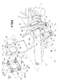
Fig. 10 is an exploded perspective view showing an example in which the protective cover is mounted at a wrong position; -
Fig. 11 is a sectional view showing an example manner in which the protective cover is prevented from being mounted at a wrong position; -
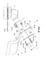
Fig. 12 is an exploded perspective view of the protective cover mounting structure for the bush cutter having a string-type cutter blade attached to the cutter body; -
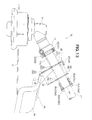
Fig. 13 is a sectional view of the protective cover mounting structure shown inFig. 12 ; and -
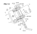
Fig. 14 is a sectional view of the protective cover mounting structure ofFig. 13 duly assembled to the bush cutter. - Now, a description will be given about an embodiment of a protective cover mounting structure for a bush cutter, with reference to the accompanying drawings, in which the terms "front" and "rear" are used hereinbelow to refer to directions as viewed from a human operator operating a bush cutter.
- As shown in
Fig. 1 , thebush cutter 10 includes acutter blade 13 replaceably attached to abush cutter body 11, an operating rod (operating frame) 17 extending from a frame support section 12 (see alsoFig. 2 ) of thebush cutter body 11, and the protectivecover mounting structure 20 provided on theframe support section 12 near aproximal end portion 17a of theoperating rod 17. - The
bush cutter 10 also includes anengine 22 provided on adistal end portion 17b of theoperating rod 17, adrive shaft 23 inserted through theoperating rod 17 for transmitting rotation of theengine 22 to thecutter blade 13, anengagement section 24 provided on theoperating rod 17 near thedistal end portion 17b, and anoperating handle 25 provided on a substantial longitudinally-middle portion of theoperating rod 17. - When cutting weed and
grass 27 using thebush cutter 10, the human operator hangs ashoulder belt 29 on his or her upper body orshoulder 28a and engages a distal end portion of thebelt 29 with theengagement section 24 to thereby support thebush cutter 10 by theupper body shoulder 28a. In this state, the human operator can cut weed, grass orbush 27 by activating theengine 22 to rotate thecutter blade 13 and swinging theoperating rod 17 in left-right and up-down directions while holding left andright grips 25a with both hands. - With the
bush cutter 10, thecutter blade 13 to be replaceably attached to thecutter body 11 is selectable from among a rotary blade 14 (Fig. 2 ), a string-type cutter blade (nylon blade) (Fig. 13 ) and the like, depending on an intended purpose. - Further, the protective
cover mounting structure 20 is constructed to allow a mounted position of aprotective cover 34 to be changed or adjusted when thecutter blade 13 has been replaced with therotary cutter blade 14, string-type cutter blade 15 or the like, so as to appropriately cover a rear upper portion of the newly attachedrotary cutter blade 14, string-type cutter blade 15 or the like. - Next, the construction of the protective
cover mounting structure 20 will be described in greater detail. First, with reference toFigs. 2 to 11 , the following describe an example where therotary cutter blade 14 is attached to thecutter body 11 as thecutter blade 13. - As shown in
Fig. 2 to 4 , theproximal end portion 17a of theoperating rod 17 is connected to theframe support section 12, and theframe support section 12 has left and right upper threadedholes holes 32 and 33 (seeFigs. 10 and12 for the right lower threaded hole 33) in such a manner that the threadedholes operating rod 17. - The protective
cover mounting structure 20 includes: theprotective cover 34 for covering a rear upper portion of the cutter blade 13 (in this case, rotary cutter blade 14) attached to thecutter body 11; aplate member 35 for positioning theprotective cover 34; first to fourth bolts (i.e., a plurality of bolts) 36 screwable into the above-mentioned threadedholes plate member 35 and theprotective cover 34 to theframe support section 12; and asheet member 42 for connecting together the first tofourth bolts 36. - The
protective cover 34 includes acover body 44 for covering a rear upper portion of therotary cutter blade 14 attached to thecutter body 11, and acover mounting section 45 extending upward from afront end portion 44a of thecover body 44. - The
cover mounting section 45 has a substantially U-shapedmounting groove portion 46 having an upward opening 46a, a left projectingportion 47 projecting rearward from the upper end of a left wall portion defining the left edge of the opening 46a, and a right projectingportion 48 projecting rearward from the upper end of a right wall portion defining the right edge of the opening 46a. - Namely, the left projecting
portion 47 is provided adjacent to the upper left side of themounting groove portion 46, while the right projectingportion 48 is provided adjacent to the upper right side of themounting groove portion 46. By the provision of the left and right projectingportions cover mounting section 45, it is possible to prevent theplate member 35 from being mounted at a wrong position deviated from a predetermined position corresponding to a type of thecutter blade 13 attached to thecutter body 11. Therefore, theplate member 35 can be reliably mounted at the predetermined position, so that theprotective cover 34 can be mounted at a predetermined position corresponding to the attached cutter blade. Functions of the left and right projectingportions Figs. 10 and11 . - The
operating rod 17 is fittable in themounting groove portion 46 through the upward opening 46a. Namely, theoperating rod 17 can be positioned in theupward opening 46a closed to thebottom surface 46b (i.e., in a lower position) as shown inFig. 4 and positioned in theupward opening 46a away from thebottom surface 46b (i.e., in an upper position) as shown inFigs. 10 and12 . - Further, the
cover mounting section 45 has: left and right upper adjustingholes 51 formed in upper end regions of the left and right wall portions with a predetermined horizontal interval S1 therebetween; left and right middle adjustingholes 52 formed in middle regions of the left and right wall portions with the predetermined horizontal interval S1 therebetween; and left and right lower adjustingholes 53 formed in lower end regions of the left and right wall portions with the predetermined horizontal interval S1 therebetween. - Further, the left
upper adjusting hole 51, leftmiddle adjusting hole 52 and leftlower adjusting hole 53 are aligned vertically on an imaginary straight line with predetermined equal vertical intervals S2 therebetween. Similarly, the rightupper adjusting hole 51, rightmiddle adjusting hole 52 and rightlower adjusting hole 53 are aligned vertically on an imaginary straight line with predetermined intervals S2 therebetween. - The
plate member 35 is in the form of a vertically elongated plate member; that is, a vertical dimension between oneend side 35a and theother end side 35b of theplate member 35 is greater than a horizontal dimension between left andright sides 35d and 35c of theplate member 35. - The
plate member 35 has a plate through-hole 55 formed in a region 35d thereof close to the oneend side 35a, and first to fourth mounting holes 56 to 59 formed around the plate through-hole 55. - When the
rotary cutter blade 14 is to be attached to thebush cutter 10, the human operator positions theplate member 35 in such a manner that the plate through-hole 55 is located in a lower position close to thebottom surface 46b. Because theplate member 35 is in the form of a vertically elongated plate member as noted above, the substantially U-shaped mountinggroove portion 46 can be covered with theplate member 35 mounted to thecover mounting section 45; namely, the mountinggroove portion 46 can be masked with theplate member 35 in such a manner that it is invisible to the human operator. - The plate through-
hole 55 is a circular hole formed for passage therethrough of the operatingrod 17. Thus, theplate member 35 can be connected to the operatingrod 17 by the operatingrod 17 being passed through the plate through-hole 55. In this way, theplate member 35 can be prevented from falling off the operatingrod 17 to get lost, when the first tofourth bolts 36 are loosened to change or adjust the mounted position of theprotective cover 34. - The first and second mounting holes 56 and 57 of the
plate member 35 are located with the predetermined horizontal interval S1 therebetween, and the third and fourth mounting holes 58 and 59 of theplate member 35 are located with the predetermined horizontal interval S1 therebetween. Further, the first and third mountingholes holes - As shown in
Figs. 4 to 6 , thesheet member 42, which is in the form of a rectangular resin-made plate, has a sheet through-hole 62 formed centrally therein, and first to fourthengaging hole portions 63 formed therein around the sheet through-hole 62. The sheet through-hole 62 is a circular hole formed for passage therethrough of the operatingrod 17. - The first and second
engaging hole portions 63 are located with the predetermined horizontal interval S1 therebetween, and the third and fourthengaging hole portions 63 are located with the predetermined horizontal interval S1 therebetween. The first and thirdengaging hole portions 63 are located with the predetermined vertical interval S2 therebetween, and the second and fourthengaging hole portions 63 are located with the predetermined vertical interval S2 therebetween. The first tofourth bolts 36 are engaged in corresponding ones of the engaginghole portions 63. - As shown in
Fig. 7 , thesheet member 42 has, for each of the engaging hole portions 63 (only the secondengaging hole portion 63 is shown in the figure), a plurality ofslits 68 formed to extend radially outwardly from an outerperipheral edge 63a of the engaginghole portion 63, and asmall hole 69 formed at the distal end of each of theslits 68. By the provision of the radial slits 68 formed in angularly spaced apart relation to one another along the outerperipheral edge 63a of the engaginghole portion 63, a portion of thesheet member 42 near the outerperipheral edge 63a of each of the engaginghole portion 63 is formed as a plurality of divided regions (hereinafter referred to as "peripheral flaps") 71. Thus, theperipheral flaps 71 of the res-in-madesheet member 42 can be resiliently deformed. - As shown in
Fig. 5 , each of thebolts 36 includes ahead portion 36a having ahexagonal hole 36b formed in its top surface and engaged at itsannular groove portion 36e in the secondengaging hole portion 63, aneck portion 36c extending coaxially from thehead portion 36a, and a threadedportion 36d extending coaxially from theneck portion 36c. - A lock washer (spring washer) 73 and a
flat washer 74 are fitted over theneck portion 36c. Thelock washer 73 and theflat washer 74 each have an inner diameter smaller than an outer diameter D of the threadedportion 36d, so that thelock washer 73 and theflat washer 74 can be retained on theneck portion 36c. - The
head portion 36a of thesecond bolt 36 has the annularengaging groove 36e formed in the outer peripheral surface thereof between thehexagonal hole 36b and theneck portion 36c and engageable in the secondengaging hole portion 63. As shown inFig. 7 , thesheet member 42 has the resiliently deformableperipheral flaps 71 extending radially outwardly from the outerperipheral edge 63a of each of the engaging hole portions 63 (only the secondengaging hole portions 63 is shown in the figure). Thus, as thehead portion 36a is inserted into the corresponding engaginghole portion 63 from itstop end region 36f (Fig. 5 ), theperipheral flaps 71 can be resiliently deformed. - By such resilient deformation of the
peripheral flaps 71, thehead portion 36a of thebolt 36 can be easily inserted into the engaginghole portion 63, so that the annularengaging groove 36e can be readily fitted and engaged in the engaginghole portion 63 of thesheet member 42. - Although not particularly described, the first, third and
fourth bolts 36 are constructed similarly to one another, i.e. each have the engaginggroove 36e in itshead portion 36a, as shown inFig. 4 , and the first, third and fourthengaging hole portions 63 are constructed similarly to one another, i.e. each have the plurality ofslits 68 extending radially outwardly from the outerperipheral edge 63a, as shown inFig. 6 . - Thus, the engaging
grooves 36e of the first, second, third andfourth bolts 36 can be readily engaged in the first, second, third and fourthengaging hole portions 63, respectively, of thesheet member 42. In this manner, thesheet member 42 can snugly engage thehead portions 36a of the first tofourth bolts 36, so that the first tofourth bolts 36 can be connected together by thesheet member 42. - Further, because the sheet through-
hole 62 is formed to permit passage therethrough of the operatingrod 17, the first tofourth bolts 36 can be connected to the operatingrod 17 via thesheet member 42. Thus, the first tofourth bolts 36 can be prevented from falling off the operatingrod 17 to get lost, when the first tofourth bolts 36 are loosened to adjust the mounted position of theprotective cover 34. - Further, as shown in
Fig. 4 , thesheet member 42 engages therespective head portions 36 of the first tofourth bolts 36 with the first andsecond bolts 36 located with the predetermined horizontal interval S1 therebetween and the third tofourth bolts 36 located with the predetermined horizontal interval S1 therebetween, and with the first andthird bolts 36 located with the predetermined vertical interval S2 therebetween and the second andfourth bolts 36 located with the predetermined vertical interval S2 therebetween. - The following describe an example manner in which the
protective cover 34 is fixed by means of the first tofourth bolts 36. To facilitate understanding, the first tofourth bolts 36 will hereinafter be referred as "first bolt 36A", "second bolt 36B", "third bolt 36C" and "fourth bolt 36D", respectively. - When the
rotary cutter blade 14 is attached to thebush cutter 10, the human operator positions theplate member 35 in such a manner that the plate through-hole 55 is located in the lower position, as shown inFig. 4 . - Then, as shown in
Figs. 4 and8 , the threadedportion 36d of thefirst bolt 36A is passed through the first mountinghole 56 of theplate member 35 and leftmiddle adjusting hole 52 of thecover mounting section 45, and then screwed into the left upper threadedhole 30 of theframe support section 12. - Further, the threaded
portion 36d of thesecond bolt 36B is passed through the second mountinghole 57 of theplate member 35 and rightmiddle adjusting hole 52 of thecover mounting section 45, and then screwed into the right upper threadedhole 31 of theframe support section 12. - Further, the threaded
portion 36d of thethird bolt 36C is passed through the third mountinghole 58 of theplate member 35 and leftlower adjusting hole 53 of thecover mounting section 45, and then screwed into the left lower threadedhole 32 of theframe support section 12. - Furthermore, the threaded
portion 36d of thefourth bolt 36D is passed through the four mountinghole 59 of theplate member 35 and rightlower adjusting hole 53 of thecover mounting section 45, and then screwed into the right lower threaded hole 33 (seeFigs. 10 and12 ) of theframe support section 12. - Namely, as shown in
Fig. 9 , the first andsecond bolts holes fourth bolts holes - Thus, the
cover mounting section 45 and theplate member 35 can be fixed to theframe support section 12 with theplate member 35 lapped on thecover mounting section 45. More specifically, thecover mounting section 45 and theplate member 35 are fixed to aregion 12a of theframe support section 12 near theproximal end portion 17a of the operatingrod 17. - In this state, the
other end side 35b of theplate member 35 is located under the left and right projectingportions cover mounting section 45 and hence does not interfere with the left and right projectingportions other end side 35b of theplate member 35 does not interfere with the left and right projectingportions plate member 35 can be mounted at the predetermined position with the plate through-hole 55 located in the lower position (seeFig. 4 ). - Thus, the plate through-
hole 55 is located adjacent to thebottom surface 46b of the mountinggroove portion 46, and the operatingrod 17 passed through the plate through-hole 55 is retained adjacent to thebottom surface 46b of the mountinggroove portion 46, as shown inFig. 6 . - In this way, the
protective cover 34 can be mounted at the predetermined position, corresponding to therotary cutter blade 14, by use of theplate member 35. Because the mountinggroove portion 46 can be covered with theplate member 35 duly mounted to thecover mounting section 45, the mountinggroove portion 46 can be masked in such a manner that it is invisible to the human operator. - In the
bush cutter 10, when the mounted position of theprotective cover 34 is to be adjusted in response to thecutter blade 13 being replaced with therotary cutter blade 14 or string-type cutter blade 15 (seeFig. 13 ), theprotective cover 34 can be detached and re-attached by loosening and tightening the first tofourth bolts 36A to 36D. - When loosening or tightening the first to
fourth bolts 36A to 36D, the human operator normally tries to loosen or tighten all of the first tofourth bolts 36A to 36D by uniform amounts, in order to prevent stress from concentrating on a particular region near any of the first to fourthengaging hole portions 63. However, the human operator may sometimes tighten or loosen only one of the first tofourth bolts 36A to 36D, in which case a region rear the outerperipheral edge 63a (Fig. 6 ) of the corresponding engaginghole portion 63 may undesirably deform locally and stress may concentrate on the region rear the outerperipheral edge 63a, thereby causing a crack. - This is why the plurality of
slits 68 are formed to extend radially outwardly from the outerperipheral edge 63a of each of the engaginghole portions 63 of thesheet member 42 so that the region near the outerperipheral edge 63a is provided as the plurality peripheral flaps 71 (seeFig. 7 ). - With the aforementioned arrangements, the instant embodiment allows the
peripheral flaps 71 to resiliently deform as the human operator tightens or loosens only one of thebolts 36A to 36D and prevents stress from concentrating on the region near the corresponding engaginghole portion 63. In this way, the instant embodiment can present a crack from occurring in the region near the outerperipheral edge 63a of any of the engaginghole portion 63 and prevent the region near the outerperipheral edge 63a from being damaged, with the result that it can reliably prevent thebolts 36A to 36D from falling off the engaginghole portions 63. - With reference to
Figs. 10 and11 , a description will be given about an example manner in which the embodiment of the protective cover mounting structure prevents theprotective cover 34 from being mounted at a wrong position. - The human operator might mistakenly insert the first and
second bolts fourth bolts middle adjusting holes 52 with theproximal end portion 17a of the operatingrod 17 and plate through-hole 55 positioned in the upper position in theupward opening 46a away from thebottom surface 46b. In such a case, theprotective cover 34 would be mounted at a wrong position that does not correspond, for example, to therotary cutter blade 14. If theprotective cover 34 is mounted at a wrong position like this, there would occur the inconvenience, among others, that the mountinggroove portion 46 of thecover mounting section 45 cannot be covered with theplate member 35. - This is why the instant embodiment of the protective cover mounting structure includes the
left projecting portion 47 projecting rearward from the upper end of the left wall portion defining the left edge of theopening 46a, and theright projecting portion 48 projecting rearward from the upper end of the right wall portion defining the edge of theopening 46a. Thus, if theplate member 35 is positioned at a wrong position, deviated from the predetermined position, in such a manner that theproximal end portion 17a of the operatingrod 17 and plate through-hole 55 are positioned in theupward opening 46a away from thebottom surface 46b, theplate member 35 would abut against the left and right projectingportions - With the
plate member 35 abutting against the left and right projectingportions plate member 35 is retained floating at a predetermined distance from thecover mounting section 45, so that the first andsecond bolts holes fourth bolts holes fourth bolts 36 from being mistakenly screwed into the upper threadedholes holes - Namely, by the provision of the left and right projecting
portions cover mounting section 45, the human operator can readily know that he or she is mounting theplate member 35 at a wrong position, and thus can mount theplate member 35 at the predetermined position with increased ease. - By merely mounting the
plate member 35 at the predetermined position, the human operator can readily mount theprotective cover 34 at the predetermined position (as shown inFig. 2 ) by use of theplate member 35. As a consequence, the human operator can readily mount theprotective cover 34 at the predetermined position corresponding to the cutter blade (in this case, rotary cutter blade 14) attached to the cutter body, which can therefore achieve an enhanced operability of the bush cutter. - Next, with reference to
Figs. 12 to 14 , a description will be given about an example where the string-type cutter blade 15 is attached to thecutter body 11 as thecutter blade 13. - When the string-
type cutter blade 15 is attached to thecutter body 11, the human operator positions theplate member 35 in such a manner that the plate through-hole 55 is located in the upper position in theupward opening 46a remote from thebottom surface 46b. - Then, the human operator inserts the threaded
portion 36d of thefirst bolt 36A into the fourth mountinghole 59 of theplate member 35 and into the leftupper adjusting hole 51 of thecover mounting section 45, and then screws the threadedportion 36d, having passed through the leftupper adjusting hole 51, into the left upper threadedhole 30. Further, the human operator inserts the threadedportion 36d of thesecond bolt 36B into the third mountinghole 58 of theplate member 35 and into the rightupper adjusting hole 51 of thecover mounting section 45, and then screws the threadedportion 36d, having passed through the rightupper adjusting hole 51, into the right upper threadedhole 31. - Further, the human operator inserts the threaded
portion 36d of thethird bolt 36C into the second mountinghole 57 of theplate member 35 and into the rightmiddle adjusting hole 52 of thecover mounting section 45, and then screws the threadedportion 36d, having passed through the leftmiddle adjusting hole 52, into the left lower threadedhole 32. Furthermore, the human operator inserts the threadedportion 36d of thefourth bolt 36D into the first mountinghole 56 of theplate member 35 and into the rightmiddle adjusting hole 52 of thecover mounting section 45, and then screws the threadedportion 36d, having passed through the rightmiddle adjusting hole 52, into the right lower threadedhole 33. - In the aforementioned manner, the first and
second bolts holes fourth bolts holes Fig. 14 . - Thus, the
cover mounting section 45 and theplate member 35 can be fixed to theframe support section 12 with theplate member 35 lapped on thecover mounting section 45. More specifically, thecover mounting section 45 and theplate member 35 are fixed to theregion 12a of theframe support section 12 near theproximal end portion 17a of the operatingrod 17. - In this state, the one
end side 35a of theplate member 35 is located under the left and right projectingportions portions end side 35a of theplate member 35 does not interfere with the left and right projectingportions plate member 35 can be mounted at th predetermined position with the plate through-hole 55 located in the upper position (seeFig. 12 ) in theopening 46a away from thebottom surface 46b. - With the plate through-
hole 55 located in the upper position in theopening 46a away from thebottom surface 46b, the operatingrod 17 passed through the plate through-hole 55 is retained in the upper position away from thebottom surface 46b of the mountinggroove portion 46. - In this way, the
protective cover 34 can be mounted at the predetermined position, corresponding to the string-type cutter blade 15, by use of theplate member 35. Because the mountinggroove portion 46 of thecover mounting section 45 can be covered with theplate member 35 mounted to thecover mounting section 45, the mountinggroove portion 46 can be masked in such a manner that it is invisible to the human operator. - It should be appreciated that the protective
cover mounting structure 20 is not limited to the above-described embodiment and may be modified variously. - For example, whereas the embodiment has been described above in relation to the case where the left and right projecting
portions cover mounting section 45, such projectingportions cover mounting section 45. - Further, whereas the embodiment has been described above in relation to the case where the four, i.e. first to fourth, bolts 36 (36A, 36B, 36C and 36D) are used as bolts for mounting the
protective cover 34 to thecutter body 11, the present invention is not so limited, and any other number of the mounting bolts than four, such as three, may be used. - Further, the
bush cutter 10,cutter body 11,cutter blade 13,rotary cutter blade 14, string-type cutter blade 15, operatingrod 17,protective cover 34,plate member 35, bolt 36 (36A, 36B, 36C or 36D),head portion 36a, engaginggroove 36e,sheet member 42, left and right projectingportions hole 55, sheet through-hole 62, engaginghole portion 63, outerperipheral edge 63a, slit 68, etc. are not limited to the above-described shapes and constructions and may be modified as necessary. - The present invention is well suited for application to bush cutters which include an operating rod extending from a cutter body, a cutter blade rotatably mounted on the cutter body, and a protective cover covering the cutter blade.
- A protective cover mounting structure (20) for a bush cutter (10), which includes an operating rod (17) extending from a cutter body (11), mounts a protective cover (34) to the cutter body by means of a plurality of bolts (36) near a proximal end portion (17a) of the operating rod. The protective cover mounting structure includes a sheet member (42) engageable with respective head portions (36a) of the plurality of bolts (36) so that the plurality of bolts (36) are connected together by the sheet member, and the sheet member has a through-hole (62) formed therein for passage therethrough of the operating rod.
Claims (4)
- A protective cover mounting structure (20) for a bush cutter (10) that includes an operating rod (17) extending from a cutter body (11), a cutter blade (13) replaceably attached to the cutter body (11) and a protective cover (34) for covering the cutter blade, the protective cover mounting structure (20) mounting the protective cover (34) to the cutter body by means of a plurality of bolts (36), near a proximal end portion (17a) of the operating rod (17), in such a manner that the protective cover (34) is adjustable in mounted position in correspondence with a type of the cutter blade (13) attached to the cutter body,
characterized in that the protective cover mounting structure (20) comprises a sheet member (42) engageable with respective head portions (36a) of the plurality of bolts (36) so that the plurality of bolts are connected together by the sheet member (42), and in that the sheet member (42) has a through-hole (62) formed therein for passage therethrough of the operating rod. - The protective cover mounting structure of claim 1, wherein the head portions (36a) of the bolts each have an annular engaging groove (36e) formed in an outer peripheral surface thereof and the sheet member (42) has a plurality of engaging hole portions (63) engageable with the annular engaging grooves (36e) of corresponding ones of the bolts, and in that each of the engaging hole portions (63) in the sheet member (42) has at least one slit (68) formed to extend radially outwardly from an outer peripheral edge (63a) of the engaging hole portion.
- The protective cover mounting structure of claim 2, further comprising: a plate member (35) mountable to the protective cover (34) by means of the plurality of bolts (36); and a projecting portion (47, 48) provided on the protective cover (34) for positioning the plate member (35) at a predetermined position corresponding to a type of the cutter blade attached to the cutter body, wherein, when the plate member (35) is positioned at a wrong position deviated from the predetermined position, the plate member (35) is prevented by the projecting portion (47, 48) from being mounted to the protective cover (34).
- The protective cover mounting structure of claim 3, wherein the plate member (35) has a through-hole (55) formed therein for passage therethrough of the operating rod.
Applications Claiming Priority (1)
| Application Number | Priority Date | Filing Date | Title |
|---|---|---|---|
| JP2010061294A JP4926259B2 (en) | 2010-03-17 | 2010-03-17 | Brush cover protective cover mounting structure |
Publications (2)
| Publication Number | Publication Date |
|---|---|
| EP2366276A1 true EP2366276A1 (en) | 2011-09-21 |
| EP2366276B1 EP2366276B1 (en) | 2013-06-05 |
Family
ID=44201199
Family Applications (1)
| Application Number | Title | Priority Date | Filing Date |
|---|---|---|---|
| EP20110158479 Not-in-force EP2366276B1 (en) | 2010-03-17 | 2011-03-16 | Protective cover mounting structure for bush cutter |
Country Status (3)
| Country | Link |
|---|---|
| EP (1) | EP2366276B1 (en) |
| JP (1) | JP4926259B2 (en) |
| ES (1) | ES2413284T3 (en) |
Citations (3)
| Publication number | Priority date | Publication date | Assignee | Title |
|---|---|---|---|---|
| US5493784A (en) * | 1992-11-20 | 1996-02-27 | Kioritz Corporation | Blade cover for cutting machine |
| JPH09205843A (en) | 1996-01-29 | 1997-08-12 | Nikkari Co Ltd | Mowing-off machine |
| EP2263440A1 (en) * | 2009-06-18 | 2010-12-22 | Makita Corporation | Coupling apparatus for coupling blade protector to tool body of gardening tool |
Family Cites Families (2)
| Publication number | Priority date | Publication date | Assignee | Title |
|---|---|---|---|---|
| JPS5733124A (en) * | 1980-08-04 | 1982-02-23 | Kubota Ltd | Conveyor for particulate material |
| JPS59196017A (en) * | 1983-04-23 | 1984-11-07 | 吉川 毅 | Wall material and block having grass planting holes |
-
2010
- 2010-03-17 JP JP2010061294A patent/JP4926259B2/en not_active Expired - Fee Related
-
2011
- 2011-03-16 EP EP20110158479 patent/EP2366276B1/en not_active Not-in-force
- 2011-03-16 ES ES11158479T patent/ES2413284T3/en active Active
Patent Citations (3)
| Publication number | Priority date | Publication date | Assignee | Title |
|---|---|---|---|---|
| US5493784A (en) * | 1992-11-20 | 1996-02-27 | Kioritz Corporation | Blade cover for cutting machine |
| JPH09205843A (en) | 1996-01-29 | 1997-08-12 | Nikkari Co Ltd | Mowing-off machine |
| EP2263440A1 (en) * | 2009-06-18 | 2010-12-22 | Makita Corporation | Coupling apparatus for coupling blade protector to tool body of gardening tool |
Also Published As
| Publication number | Publication date |
|---|---|
| EP2366276B1 (en) | 2013-06-05 |
| ES2413284T3 (en) | 2013-07-16 |
| JP4926259B2 (en) | 2012-05-09 |
| JP2011193746A (en) | 2011-10-06 |
Similar Documents
| Publication | Publication Date | Title |
|---|---|---|
| US10874048B2 (en) | Convertible cap and head system | |
| EP2482631B1 (en) | Plant-cutting assembly for a header | |
| CA2242213C (en) | String trimmer with fixed string head | |
| US6829878B1 (en) | Quick change disc knife mounting mechanism | |
| EP3888441B1 (en) | Mowing device for a lawnmower and / or a strimmer, lawnmower and / or a strimmer and method for mounting a mowing device and / or a lawnmower and / or a strimmer | |
| US6189307B1 (en) | Fastener assembly for attachment of composite insert to mower deck | |
| US20150305236A1 (en) | Rock guard for quick change knives on a disc mower | |
| DK2988585T3 (en) | DOUBLE CUTTING CUTTER | |
| EP3385017A1 (en) | Hand-held cutter | |
| US5940973A (en) | Trimmer guide | |
| KR20160002308A (en) | Slicer | |
| EP2366276B1 (en) | Protective cover mounting structure for bush cutter | |
| JP3735322B2 (en) | Tillage claw attachment device and forward / reverse rotary tillage device | |
| CA1120334A (en) | Double disk opener assembly and disk blade therefor | |
| CA2359598A1 (en) | Crop harvesting header with angle adjustment of the knife guards | |
| EP2366277B1 (en) | Protective cover mounting structure for bush cutter | |
| AU2009279338B2 (en) | Offset guard bolt attachment system | |
| JPH09205843A (en) | Mowing-off machine | |
| US20060179663A1 (en) | Trimmer head | |
| KR102425045B1 (en) | Combined structure of mower blade safety device | |
| US20080293313A1 (en) | Demountable Cable Cutter | |
| CA2722060A1 (en) | Sickle assembly | |
| JPH0137374Y2 (en) | ||
| KR101808703B1 (en) | Lawn trimmer | |
| KR101570807B1 (en) | cutter for weeding and mowing |
Legal Events
| Date | Code | Title | Description |
|---|---|---|---|
| PUAI | Public reference made under article 153(3) epc to a published international application that has entered the european phase |
Free format text: ORIGINAL CODE: 0009012 |
|
| 17P | Request for examination filed |
Effective date: 20110316 |
|
| AK | Designated contracting states |
Kind code of ref document: A1 Designated state(s): AL AT BE BG CH CY CZ DE DK EE ES FI FR GB GR HR HU IE IS IT LI LT LU LV MC MK MT NL NO PL PT RO RS SE SI SK SM TR |
|
| AX | Request for extension of the european patent |
Extension state: BA ME |
|
| 17Q | First examination report despatched |
Effective date: 20120730 |
|
| GRAP | Despatch of communication of intention to grant a patent |
Free format text: ORIGINAL CODE: EPIDOSNIGR1 |
|
| GRAS | Grant fee paid |
Free format text: ORIGINAL CODE: EPIDOSNIGR3 |
|
| GRAA | (expected) grant |
Free format text: ORIGINAL CODE: 0009210 |
|
| AK | Designated contracting states |
Kind code of ref document: B1 Designated state(s): AL AT BE BG CH CY CZ DE DK EE ES FI FR GB GR HR HU IE IS IT LI LT LU LV MC MK MT NL NO PL PT RO RS SE SI SK SM TR |
|
| REG | Reference to a national code |
Ref country code: GB Ref legal event code: FG4D |
|
| REG | Reference to a national code |
Ref country code: CH Ref legal event code: EP |
|
| REG | Reference to a national code |
Ref country code: AT Ref legal event code: REF Ref document number: 615080 Country of ref document: AT Kind code of ref document: T Effective date: 20130615 |
|
| REG | Reference to a national code |
Ref country code: IE Ref legal event code: FG4D |
|
| REG | Reference to a national code |
Ref country code: ES Ref legal event code: FG2A Ref document number: 2413284 Country of ref document: ES Kind code of ref document: T3 Effective date: 20130716 |
|
| REG | Reference to a national code |
Ref country code: DE Ref legal event code: R096 Ref document number: 602011001880 Country of ref document: DE Effective date: 20130801 |
|
| REG | Reference to a national code |
Ref country code: AT Ref legal event code: MK05 Ref document number: 615080 Country of ref document: AT Kind code of ref document: T Effective date: 20130605 |
|
| PG25 | Lapsed in a contracting state [announced via postgrant information from national office to epo] |
Ref country code: AT Free format text: LAPSE BECAUSE OF FAILURE TO SUBMIT A TRANSLATION OF THE DESCRIPTION OR TO PAY THE FEE WITHIN THE PRESCRIBED TIME-LIMIT Effective date: 20130605 Ref country code: SI Free format text: LAPSE BECAUSE OF FAILURE TO SUBMIT A TRANSLATION OF THE DESCRIPTION OR TO PAY THE FEE WITHIN THE PRESCRIBED TIME-LIMIT Effective date: 20130605 Ref country code: NO Free format text: LAPSE BECAUSE OF FAILURE TO SUBMIT A TRANSLATION OF THE DESCRIPTION OR TO PAY THE FEE WITHIN THE PRESCRIBED TIME-LIMIT Effective date: 20130905 Ref country code: LT Free format text: LAPSE BECAUSE OF FAILURE TO SUBMIT A TRANSLATION OF THE DESCRIPTION OR TO PAY THE FEE WITHIN THE PRESCRIBED TIME-LIMIT Effective date: 20130605 Ref country code: GR Free format text: LAPSE BECAUSE OF FAILURE TO SUBMIT A TRANSLATION OF THE DESCRIPTION OR TO PAY THE FEE WITHIN THE PRESCRIBED TIME-LIMIT Effective date: 20130906 Ref country code: SE Free format text: LAPSE BECAUSE OF FAILURE TO SUBMIT A TRANSLATION OF THE DESCRIPTION OR TO PAY THE FEE WITHIN THE PRESCRIBED TIME-LIMIT Effective date: 20130605 Ref country code: FI Free format text: LAPSE BECAUSE OF FAILURE TO SUBMIT A TRANSLATION OF THE DESCRIPTION OR TO PAY THE FEE WITHIN THE PRESCRIBED TIME-LIMIT Effective date: 20130605 |
|
| REG | Reference to a national code |
Ref country code: NL Ref legal event code: VDEP Effective date: 20130605 |
|
| REG | Reference to a national code |
Ref country code: LT Ref legal event code: MG4D |
|
| PG25 | Lapsed in a contracting state [announced via postgrant information from national office to epo] |
Ref country code: BG Free format text: LAPSE BECAUSE OF FAILURE TO SUBMIT A TRANSLATION OF THE DESCRIPTION OR TO PAY THE FEE WITHIN THE PRESCRIBED TIME-LIMIT Effective date: 20130905 Ref country code: RS Free format text: LAPSE BECAUSE OF FAILURE TO SUBMIT A TRANSLATION OF THE DESCRIPTION OR TO PAY THE FEE WITHIN THE PRESCRIBED TIME-LIMIT Effective date: 20130605 Ref country code: HR Free format text: LAPSE BECAUSE OF FAILURE TO SUBMIT A TRANSLATION OF THE DESCRIPTION OR TO PAY THE FEE WITHIN THE PRESCRIBED TIME-LIMIT Effective date: 20130605 |
|
| PG25 | Lapsed in a contracting state [announced via postgrant information from national office to epo] |
Ref country code: LV Free format text: LAPSE BECAUSE OF FAILURE TO SUBMIT A TRANSLATION OF THE DESCRIPTION OR TO PAY THE FEE WITHIN THE PRESCRIBED TIME-LIMIT Effective date: 20130605 |
|
| PG25 | Lapsed in a contracting state [announced via postgrant information from national office to epo] |
Ref country code: PT Free format text: LAPSE BECAUSE OF FAILURE TO SUBMIT A TRANSLATION OF THE DESCRIPTION OR TO PAY THE FEE WITHIN THE PRESCRIBED TIME-LIMIT Effective date: 20131007 Ref country code: IS Free format text: LAPSE BECAUSE OF FAILURE TO SUBMIT A TRANSLATION OF THE DESCRIPTION OR TO PAY THE FEE WITHIN THE PRESCRIBED TIME-LIMIT Effective date: 20131005 Ref country code: CZ Free format text: LAPSE BECAUSE OF FAILURE TO SUBMIT A TRANSLATION OF THE DESCRIPTION OR TO PAY THE FEE WITHIN THE PRESCRIBED TIME-LIMIT Effective date: 20130605 Ref country code: EE Free format text: LAPSE BECAUSE OF FAILURE TO SUBMIT A TRANSLATION OF THE DESCRIPTION OR TO PAY THE FEE WITHIN THE PRESCRIBED TIME-LIMIT Effective date: 20130605 Ref country code: BE Free format text: LAPSE BECAUSE OF FAILURE TO SUBMIT A TRANSLATION OF THE DESCRIPTION OR TO PAY THE FEE WITHIN THE PRESCRIBED TIME-LIMIT Effective date: 20130605 Ref country code: SK Free format text: LAPSE BECAUSE OF FAILURE TO SUBMIT A TRANSLATION OF THE DESCRIPTION OR TO PAY THE FEE WITHIN THE PRESCRIBED TIME-LIMIT Effective date: 20130605 |
|
| PG25 | Lapsed in a contracting state [announced via postgrant information from national office to epo] |
Ref country code: PL Free format text: LAPSE BECAUSE OF FAILURE TO SUBMIT A TRANSLATION OF THE DESCRIPTION OR TO PAY THE FEE WITHIN THE PRESCRIBED TIME-LIMIT Effective date: 20130605 Ref country code: RO Free format text: LAPSE BECAUSE OF FAILURE TO SUBMIT A TRANSLATION OF THE DESCRIPTION OR TO PAY THE FEE WITHIN THE PRESCRIBED TIME-LIMIT Effective date: 20130605 Ref country code: NL Free format text: LAPSE BECAUSE OF FAILURE TO SUBMIT A TRANSLATION OF THE DESCRIPTION OR TO PAY THE FEE WITHIN THE PRESCRIBED TIME-LIMIT Effective date: 20130605 |
|
| PLBE | No opposition filed within time limit |
Free format text: ORIGINAL CODE: 0009261 |
|
| STAA | Information on the status of an ep patent application or granted ep patent |
Free format text: STATUS: NO OPPOSITION FILED WITHIN TIME LIMIT |
|
| PG25 | Lapsed in a contracting state [announced via postgrant information from national office to epo] |
Ref country code: DK Free format text: LAPSE BECAUSE OF FAILURE TO SUBMIT A TRANSLATION OF THE DESCRIPTION OR TO PAY THE FEE WITHIN THE PRESCRIBED TIME-LIMIT Effective date: 20130605 |
|
| 26N | No opposition filed |
Effective date: 20140306 |
|
| REG | Reference to a national code |
Ref country code: DE Ref legal event code: R097 Ref document number: 602011001880 Country of ref document: DE Effective date: 20140306 |
|
| PG25 | Lapsed in a contracting state [announced via postgrant information from national office to epo] |
Ref country code: LU Free format text: LAPSE BECAUSE OF FAILURE TO SUBMIT A TRANSLATION OF THE DESCRIPTION OR TO PAY THE FEE WITHIN THE PRESCRIBED TIME-LIMIT Effective date: 20140316 |
|
| REG | Reference to a national code |
Ref country code: CH Ref legal event code: PL |
|
| REG | Reference to a national code |
Ref country code: IE Ref legal event code: MM4A |
|
| PG25 | Lapsed in a contracting state [announced via postgrant information from national office to epo] |
Ref country code: CH Free format text: LAPSE BECAUSE OF NON-PAYMENT OF DUE FEES Effective date: 20140331 Ref country code: LI Free format text: LAPSE BECAUSE OF NON-PAYMENT OF DUE FEES Effective date: 20140331 Ref country code: IE Free format text: LAPSE BECAUSE OF NON-PAYMENT OF DUE FEES Effective date: 20140316 |
|
| REG | Reference to a national code |
Ref country code: FR Ref legal event code: PLFP Year of fee payment: 6 |
|
| PG25 | Lapsed in a contracting state [announced via postgrant information from national office to epo] |
Ref country code: MT Free format text: LAPSE BECAUSE OF FAILURE TO SUBMIT A TRANSLATION OF THE DESCRIPTION OR TO PAY THE FEE WITHIN THE PRESCRIBED TIME-LIMIT Effective date: 20130605 |
|
| PG25 | Lapsed in a contracting state [announced via postgrant information from national office to epo] |
Ref country code: SM Free format text: LAPSE BECAUSE OF FAILURE TO SUBMIT A TRANSLATION OF THE DESCRIPTION OR TO PAY THE FEE WITHIN THE PRESCRIBED TIME-LIMIT Effective date: 20130605 |
|
| PG25 | Lapsed in a contracting state [announced via postgrant information from national office to epo] |
Ref country code: MC Free format text: LAPSE BECAUSE OF FAILURE TO SUBMIT A TRANSLATION OF THE DESCRIPTION OR TO PAY THE FEE WITHIN THE PRESCRIBED TIME-LIMIT Effective date: 20130605 |
|
| PG25 | Lapsed in a contracting state [announced via postgrant information from national office to epo] |
Ref country code: CY Free format text: LAPSE BECAUSE OF FAILURE TO SUBMIT A TRANSLATION OF THE DESCRIPTION OR TO PAY THE FEE WITHIN THE PRESCRIBED TIME-LIMIT Effective date: 20130605 |
|
| PG25 | Lapsed in a contracting state [announced via postgrant information from national office to epo] |
Ref country code: TR Free format text: LAPSE BECAUSE OF FAILURE TO SUBMIT A TRANSLATION OF THE DESCRIPTION OR TO PAY THE FEE WITHIN THE PRESCRIBED TIME-LIMIT Effective date: 20130605 Ref country code: HU Free format text: LAPSE BECAUSE OF FAILURE TO SUBMIT A TRANSLATION OF THE DESCRIPTION OR TO PAY THE FEE WITHIN THE PRESCRIBED TIME-LIMIT; INVALID AB INITIO Effective date: 20110316 |
|
| REG | Reference to a national code |
Ref country code: FR Ref legal event code: PLFP Year of fee payment: 7 |
|
| REG | Reference to a national code |
Ref country code: FR Ref legal event code: PLFP Year of fee payment: 8 |
|
| PG25 | Lapsed in a contracting state [announced via postgrant information from national office to epo] |
Ref country code: MK Free format text: LAPSE BECAUSE OF FAILURE TO SUBMIT A TRANSLATION OF THE DESCRIPTION OR TO PAY THE FEE WITHIN THE PRESCRIBED TIME-LIMIT Effective date: 20130605 |
|
| PG25 | Lapsed in a contracting state [announced via postgrant information from national office to epo] |
Ref country code: AL Free format text: LAPSE BECAUSE OF FAILURE TO SUBMIT A TRANSLATION OF THE DESCRIPTION OR TO PAY THE FEE WITHIN THE PRESCRIBED TIME-LIMIT Effective date: 20130605 |
|
| PGFP | Annual fee paid to national office [announced via postgrant information from national office to epo] |
Ref country code: DE Payment date: 20190319 Year of fee payment: 18 |
|
| PGFP | Annual fee paid to national office [announced via postgrant information from national office to epo] |
Ref country code: ES Payment date: 20190401 Year of fee payment: 9 |
|
| PGFP | Annual fee paid to national office [announced via postgrant information from national office to epo] |
Ref country code: IT Payment date: 20200221 Year of fee payment: 10 Ref country code: GB Payment date: 20200304 Year of fee payment: 10 |
|
| REG | Reference to a national code |
Ref country code: DE Ref legal event code: R119 Ref document number: 602011001880 Country of ref document: DE |
|
| PG25 | Lapsed in a contracting state [announced via postgrant information from national office to epo] |
Ref country code: DE Free format text: LAPSE BECAUSE OF NON-PAYMENT OF DUE FEES Effective date: 20201001 |
|
| PGFP | Annual fee paid to national office [announced via postgrant information from national office to epo] |
Ref country code: FR Payment date: 20210210 Year of fee payment: 11 |
|
| REG | Reference to a national code |
Ref country code: ES Ref legal event code: FD2A Effective date: 20210804 |
|
| GBPC | Gb: european patent ceased through non-payment of renewal fee |
Effective date: 20210316 |
|
| PG25 | Lapsed in a contracting state [announced via postgrant information from national office to epo] |
Ref country code: ES Free format text: LAPSE BECAUSE OF NON-PAYMENT OF DUE FEES Effective date: 20200317 |
|
| PG25 | Lapsed in a contracting state [announced via postgrant information from national office to epo] |
Ref country code: GB Free format text: LAPSE BECAUSE OF NON-PAYMENT OF DUE FEES Effective date: 20210316 |
|
| PG25 | Lapsed in a contracting state [announced via postgrant information from national office to epo] |
Ref country code: IT Free format text: LAPSE BECAUSE OF NON-PAYMENT OF DUE FEES Effective date: 20210316 |
|
| PG25 | Lapsed in a contracting state [announced via postgrant information from national office to epo] |
Ref country code: FR Free format text: LAPSE BECAUSE OF NON-PAYMENT OF DUE FEES Effective date: 20220331 |