EP2365708A2 - Method and apparatus for handling SRVCC in an inter radio access technology handover - Google Patents
Method and apparatus for handling SRVCC in an inter radio access technology handover Download PDFInfo
- Publication number
- EP2365708A2 EP2365708A2 EP11001411A EP11001411A EP2365708A2 EP 2365708 A2 EP2365708 A2 EP 2365708A2 EP 11001411 A EP11001411 A EP 11001411A EP 11001411 A EP11001411 A EP 11001411A EP 2365708 A2 EP2365708 A2 EP 2365708A2
- Authority
- EP
- European Patent Office
- Prior art keywords
- rab
- information
- handover
- command message
- rat system
- Prior art date
- Legal status (The legal status is an assumption and is not a legal conclusion. Google has not performed a legal analysis and makes no representation as to the accuracy of the status listed.)
- Granted
Links
Images



Classifications
-
- H—ELECTRICITY
- H04—ELECTRIC COMMUNICATION TECHNIQUE
- H04W—WIRELESS COMMUNICATION NETWORKS
- H04W36/00—Hand-off or reselection arrangements
- H04W36/0005—Control or signalling for completing the hand-off
- H04W36/0011—Control or signalling for completing the hand-off for data sessions of end-to-end connection
- H04W36/0022—Control or signalling for completing the hand-off for data sessions of end-to-end connection for transferring data sessions between adjacent core network technologies
- H04W36/00224—Control or signalling for completing the hand-off for data sessions of end-to-end connection for transferring data sessions between adjacent core network technologies between packet switched [PS] and circuit switched [CS] network technologies, e.g. circuit switched fallback [CSFB]
- H04W36/00226—Control or signalling for completing the hand-off for data sessions of end-to-end connection for transferring data sessions between adjacent core network technologies between packet switched [PS] and circuit switched [CS] network technologies, e.g. circuit switched fallback [CSFB] wherein the core network technologies comprise IP multimedia system [IMS], e.g. single radio voice call continuity [SRVCC]
Definitions
- an evolved universal terrestrial radio access network (“EUTRAN”) includes a plurality of evolved Node-Bs (“eNode B”s) and communicates with a plurality of mobile stations, also referred to as user equipments (“UE”s).
- eNode B evolved Node-Bs
- UE user equipments
- Intersystem handovers between LTE networks and Universal Terrestrial Radio Access Networks are expected to play an increasingly important role as many cellular network operators will likely provide wide-area coverage with UTRAN and use LTE in relatively small traffic hotspots. This will be particularly common as LTE networks are implemented and expanded.
- a multisystem UE e.g., a mobile phone or other wireless device, is capable of working on both LTE and UTRAN systems. Each time the UE moves between the two types of coverage areas, an intersystem handover is performed. These handovers are generally referred to as inter-Radio Access Technology (“inter-RAT”) handovers.
- An inter-RAT handover to UTRAN procedure hands the UE over from an LTE system to a UTRAN system.
- Single Radio Voice Call Continuity provides voice call continuity in a handover between a packet-switched (“PS”) network and a circuit-switched (“CS”) network for calls that are anchored in the IP Multimedia Subsystem when the UE is capable of transmitting/receiving on only one of those access networks at a given time.
- PS packet-switched
- CS circuit-switched
- the LTE network sends a Handover to UTRAN Command Message to the UE.
- the techniques introduced here provide a system and method for determining whether an inter-RAT handover is an SRVCC handover, and for performing the subsequent SRVCC handover.
- the techniques include receiving a handover command message that does not include SRVCC related information elements, for example, a "RAB info to replace" information element.
- SRVCC related information elements for example, a "RAB info to replace” information element.
- the UE continues with an SRVCC handover using a circuit-switched RAB provided in a "RAB information for setup" information element.
- the techniques include receiving a handover command message that does include SRVCC related information elements, though the SRVCC handover is performed by an alternative method.
- a wireless device receives a handover command message containing the "RAB info to replace" information element.
- the wireless device uses a circuit-switched RAB from the "RAB information for setup" information element to replace the packet-switched bearer currently in use by the wireless device, which is identified by a bearer identity in the "RAB info to replace" information element.
- a handover command message that does not include a "RAB info to replace" information element is considered by the wireless device as invalid.
- the invalid message is discarded and no handover is initiated.
- the wireless device may also send a handover failure message to the RAT system.
- Figure 1 shows an example of a UE.
- Figure 2 shows example architecture of an inter-working cellular network.
- Figure 3 is a high-level block diagram showing an example of the architecture of a UE.
- Figure 4 is a schematic illustration of example architecture of a UE operating system.
- Figure 5 is an example of a sequence chart for performing an inter-RAT handover procedure.
- Figure 6A is an example diagram of a Handover to UTRAN Command Message that does not include an "RAB info to replace" information element.
- Figure 6B is an example diagram of a Handover to UTRAN Command Message that does include an "RAB info to replace" information element.
- Figure 8 is a flow diagram of an alternative process for inter-RAT handover.
- FIG. 1 shows an example of a UE 100 in which the techniques introduced here can be implemented.
- the UE described here is an illustration of one type of wireless device in which the techniques can be implemented; other wireless devices may also be used for implementing the techniques.
- UEs may include cell phones, personal digital assistants ("PDA"s), portable email devices (e.g., a Blackberry ® device), portable media players (e.g., an Apple iPod Touch R ), tablet or slate computers (e.g., an Apple iPad R ), netbook computers, notebook computers, e-readers, or any other device having wireless communication capability.
- PDA personal digital assistants
- portable email devices e.g., a Blackberry ® device
- portable media players e.g., an Apple iPod Touch R
- tablet or slate computers e.g., an Apple iPad R
- netbook computers notebook computers, e-readers, or any other device having wireless communication capability.
- the UE 100 includes a display 110 used to make and receive telephone calls and display data services.
- the display 110 includes a touch-sensitive screen that allows for the direct manipulation of displayed data.
- the UE 100 has a multifunction input module 104 to operate the UE, navigate the display, and perform selections on any data.
- the input module 104 can be, for example, a keyboard, mouse, trackball, touch-sensitive screen, or any other input module capable of communicating a user selection.
- the UE 100 operates an antenna system 106 to send and receive information on a wireless network.
- FIG. 2 shows example architecture of an inter-working cellular network.
- the example network includes the UE 100, an Evolved UMTS Terrestrial Radio Access Network (“EUTRAN”) 202, an UMTS Terrestrial Radio Access Network (“UTRAN”) 204, base transceiver stations 206 and 208, evolved packet core (“EPC”) 210, and UTRAN core network 212.
- EUTRAN Evolved UMTS Terrestrial Radio Access Network
- UTRAN UMTS Terrestrial Radio Access Network
- EPC evolved packet core
- the EUTRAN 202 is a wireless communication network using the air interface defined by the 3GPP's LTE standards.
- EUTRAN is also referred to as the 3GPP work item on the Long Term Evolution and the evolved universal terrestrial radio access (EUTRA) in early drafts of the 3GPP LTE specification.
- the EUTRAN is a radio access network standard meant to replace the UMTS, High-Speed Downlink Packet Access (HSDPA), and High-Speed Uplink Packet Access (HSUPA) technologies specified in 3GPP releases 5 and beyond.
- EUTRAN provides higher data rates, lower latency, and is optimized for packet data.
- the communication infrastructure 214 is an interface that is standardized in order to allow multivendor interoperability.
- the communication infrastructure 214 can be the Internet (not shown), which allows for the transmission of information in packets over Internet Protocol (IP).
- IP Internet Protocol
- the communication infrastructure 214 can be a serial or parallel transmission line allowing for the transfer of analog and/or digital information between the evolved packet core 210 and the UTRAN core network 212.
- UE 100 is a multisystem UE configured to communicate with both the eNode Bs 206 of the EUTRAN 202 and the Node Bs 208 of the UTRAN 204.
- the UE 100 connects to an eNode B 206 or a Node B 208 using a wireless communication link 216 and 218, respectively. While the UE 100 is configured to communicate in both the EUTRAN 202 and the UTRAN 204, the UE is typically only connected to one network at a time.
- FIG. 3 is a high-level block diagram showing an example of the architecture of the UE 100.
- UE architecture 300 is a processing system that includes a processor subsystem 302 that can include one or more processors.
- the UE architecture 300 further includes a memory 304, a storage module 310, an input device 312, a display device 110, and an antenna system 106 each interconnected by an interconnect 306 and powered by a power supply 309.
- the display device 110 is configured to display information for viewing.
- Information for display can consist of textual, graphical, and/or multimedia information and is presentable in a graphical user interface.
- the display 110 includes a touch-sensitive screen that allows for the direct manipulation of displayed information.
- the displayed information can also be manipulated by the input device 312.
- the input device 312 is configured to produce a signal based on user input.
- the signal may include a user selection that conveys the user input to the processor subsystem 302 and an operating system 308, via the interconnect 306.
- the memory 304 illustratively comprises storage locations that can be addressed by the processor subsystem 302 and the UE architecture's other components for storing software program code and data structures associated with the present invention.
- the processor subsystem 302 and the associated components may, in turn, include processing elements and/or logic circuitry configured to execute the software code and manipulate the data structures.
- the operating system 308, portions of which are typically resident 304 in memory and executed by the processor subsystem 302, functionally organizes the UE architecture 300 by (among other things) configuring the processor subsystem 302 to invoke handover and proximity indication related operations according to the techniques introduced herein. It will be apparent to those skilled in the art that other processing and memory implementations, including various computer readable storage media, may be used for storing and executing program instructions pertaining to the technique introduced herein.
- the internal architecture of the base transceiver stations 206 and 208 include a communication module 106, processor subsystem 302, memory 304, and storage module 310, each configured to communicate via an interconnect 306.
- FIG 4 is a schematic illustration of an example architecture of a UE operating system.
- the UE memory 304 includes a UE operating system 400.
- the operating system 400 includes an upper layer 402, a radio resource control (RRC) layer 404, and a lower layer 406. Because the UE 100 is a multisystem device, the operating system 400 will support a protocol stack to communicate with both the UTRAN 204 and EUTRAN 202.
- the RRC layer 404 is responsible for managing radio resources by communicating with the UTRAN 204 and EUTRAN 202. Relative to the RRC layer 404, there is an upper layer 402 and a lower layer 406, each of which may include multiple protocol layers.
- the lower layer 406 can include, for example, a radio link control ("RLC") layer.
- the upper layer can include, for example, a mobility management layer.
- FIG. 5 is an example of a sequence chart for performing an inter-RAT handover procedure.
- a typical inter-RAT handover procedure includes additional steps not shown in Figure 5 .
- An inter-RAT handover procedure from EUTRAN to UTRAN is described fully in 3GPP TS 23.216 version 9.2.0 Release 9 Section 6.2, which is incorporated herein by reference.
- the sequence of the example handover in Figure 5 starts at step 501 with the UE taking and submitting measurement reports to the EUTRAN, for example, EUTRAN 202. As the UE moves farther from the EUTRAN, the communication link 216 becomes weaker and the UE updates EUTRAN with measurement reports regarding communication link strength. When the communication link strength reaches a threshold value, beyond which reliable communication is not possible, the EUTRAN decides at step 502 to initiate a handover to UTRAN.
- the EPC then, at step 504, sends a Prepare Handover Request Message to the UTRAN core.
- the Prepare Handover Request Message includes information relating to an EUTRAN radio bearer that the UE is currently using for voice data.
- the radio bearer carries packet-switched data between the UE and the EUTRAN.
- the radio bearer used for the voice signal in the EUTRAN connection is commonly referred to as an Evolved Packet System ("EPS") bearer.
- EPS Evolved Packet System
- the evolved packet core 210 performs resource allocation with the target UTRAN by sending a Relocation Request, step 505, and receiving a Relocation Acknowledgment, step 506.
- the Relocation Acknowledgment, step 506, includes a Handover to UTRAN Command Message containing the prepared CS handover information, such as the radio access bearer ("RAB”) information.
- RAB radio access bearer
- the EPS bearer identity associated with the EPS bearer that was sent from the EPC to the UTRAN through the UTRAN core is used as the bearer identity in the "RAB info to replace" information element in the Handover to UTRAN Command Message.
- the Handover to UTRAN Command Message is packaged in a target to source transparent container, step 507.
- the target to source transparent container is used to contain the Handover to UTRAN Command Message in a format that allows the UTRAN and EUTRAN to exchange information in an unchanged form.
- the EPC 210 forwards the Handover Command Message containing the target to source transparent container to the EUTRAN at step 508.
- the EUTRAN extracts the Handover to UTRAN Command Message from the target to source transparent container.
- the EUTRAN then sends the Handover to UTRAN Command Message to the UE.
- An example of a Handover to UTRAN Command Message is illustrated in Figures 6A and 6B and is described in greater detail below.
- the RRC layer 404 of the UE parses the message and determines what connections are being handed over. Having obtained the necessary information from the Handover to UTRAN Command Message, the UE 100 tunes to the UTRAN 204.
- the UE 100 After connecting to the UTRAN 204, the UE 100 transmits a Handover to UTRAN Complete Message to the UTRAN 204 at step 511.
- the UTRAN 204 sends a Relocation Complete to the UTRAN core network 212 at step 512.
- the UTRAN core network 212 then sends a Handover Complete Message to the EPC 210 at step 513.
- the "RAB identity” information element 608 uniquely identifies a radio access bearer within a core network ("CN") domain.
- the "RAB identity” information element 608 includes a circuit-switched RAB that has the same identity as the EPS bearer that is used between the UE 100 and EUTRAN 202. This allows the UE 100, during a handover, to easily swap the EPS bearer with the circuit-switched RAB that has the same identity.
- the "CN domain entity” information element 610 identifies the type of core network domain that the UTRAN employs.
- Figure 6B is an example diagram of a Handover to UTRAN Command Message 622 that includes a "RAB info to replace" information element 628.
- the example handover message of Figure 6B includes similar elements to those of the handover message of Figure 6A .
- the Handover to UTRAN Command Message 622 includes a "RAB information for setup" information element 624 and a "RAB info” information element 626, which includes a "RAB identity" information element 630 and a "CN domain entity” information element 632.
- the Handover to UTRAN Command Message 622 of Figure 6B further includes the "RAB info to replace" information element 628.
- the "RAB info to replace" information element 628 includes information to be used in completing the handover.
- the information element includes an indication of the EPS bearer currently used for the EUTRAN voice connection. This indication lets the UE 100 know which EPS bearer is to be replaced with the circuit-switched RAB associated with the UTRAN connection that is received in the handover message. Similar to the "RAB info" information element 626, the "RAB info to replace” information element includes a RAB identity 634 (i.e., the EPS bearer to be replaced) and a CN domain entity 636.
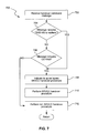
- Figure 7 is a flow diagram of a process for inter-RAT handover.
- the process is organized as a sequence of operations in the flowchart 700. However, it should be understood that at least some of the operations associated with this process can potentially be reordered, supplemented, or substituted for while still performing the same overall technique.
- a first RAT for example EUTRAN 202
- the packet-switched service is a voice call.
- the process begins at step 702, where the UE 100 receives a handover command message from the first RAT.
- the first RAT is an EUTRAN 202 and the handover is to take place to a second RAT that is a UTRAN 204
- the handover command message is a Handover to UTRAN Command Message.
- the RRC layer 404 determines whether the handover command message includes a circuit-switched RAB (CS RAB) in the "RAB information for setup" information element. If the "RAB information for setup" information element does not include a CS RAB, the RRC layer 404 determines that the handover procedure is not an SRVCC handover and, at step 712, the UE performs a non-SRVCC handover procedure.
- CS RAB circuit-switched RAB
- FIG. 8 is a flow diagram of an alternative process for inter-RAT handover.
- the process is organized as a sequence of operations in the flowchart 800. However, it should be understood that at least some of the operations associated with this process can potentially be reordered, supplemented, or substituted for while still performing the same overall technique.
- a first RAT for example, EUTRAN 202
- EUTRAN 202 has established a packet-switched service with a UE 100.
- the packet-switched service is a voice call.
- the process begins at step 802, where the UE 100 receives from the first RAT a handover command message that includes a "RAB info to replace" information element.
- the handover command message is a Handover to UTRAN Command Message.
- the process continues to step 806, where the RRC layer 404 determines that the handover is an SRVCC handover but ignores the "RAB info to replace" information element.
- the UE 100 replaces the current EPS bearer with a CS RAB in the "RAB information for setup" information element that has the same identity as the current EPS bearer.
- the RRC layer 404 determines a bearer identity for the EPS bearer that is currently used for voice service in the first RAT.
- the UE 100 finds the CS RAB in the "RAB information for setup" information element that has a corresponding bearer identity, and replaces the EPS bearer with the CS RAB.
Landscapes
- Engineering & Computer Science (AREA)
- Multimedia (AREA)
- Computer Networks & Wireless Communication (AREA)
- Signal Processing (AREA)
- Mobile Radio Communication Systems (AREA)
Abstract
Description
- In the past few decades, telephone systems have evolved continuously at an accelerated rate. Networks operating under the Universal Mobile Telecommunications System ("UMTS") Long Term Evolution ("LTE") standard, initiated by the third-generation partnership project ("3GPP"), include new radio access technology ("RAT") and core radio network architecture that provide high data rate, low latency, packet optimization, and improved system capacity and coverage. In LTE networks, an evolved universal terrestrial radio access network ("EUTRAN") includes a plurality of evolved Node-Bs ("eNode B"s) and communicates with a plurality of mobile stations, also referred to as user equipments ("UE"s).
- Intersystem handovers between LTE networks and Universal Terrestrial Radio Access Networks ("UTRAN") are expected to play an increasingly important role as many cellular network operators will likely provide wide-area coverage with UTRAN and use LTE in relatively small traffic hotspots. This will be particularly common as LTE networks are implemented and expanded. A multisystem UE, e.g., a mobile phone or other wireless device, is capable of working on both LTE and UTRAN systems. Each time the UE moves between the two types of coverage areas, an intersystem handover is performed. These handovers are generally referred to as inter-Radio Access Technology ("inter-RAT") handovers. An inter-RAT handover to UTRAN procedure hands the UE over from an LTE system to a UTRAN system.
- Single Radio Voice Call Continuity ("SRVCC") provides voice call continuity in a handover between a packet-switched ("PS") network and a circuit-switched ("CS") network for calls that are anchored in the IP Multimedia Subsystem when the UE is capable of transmitting/receiving on only one of those access networks at a given time. To perform an SRVCC handover from LTE to UTRAN, the LTE network sends a Handover to UTRAN Command Message to the UE.
- The techniques introduced here provide a system and method for determining whether an inter-RAT handover is an SRVCC handover, and for performing the subsequent SRVCC handover. The techniques according to one embodiment include receiving a handover command message that does not include SRVCC related information elements, for example, a "RAB info to replace" information element. Despite the lack of SRVCC related information elements, the UE continues with an SRVCC handover using a circuit-switched RAB provided in a "RAB information for setup" information element.
- The techniques include receiving a handover command message that does include SRVCC related information elements, though the SRVCC handover is performed by an alternative method. For example, in one embodiment, a wireless device receives a handover command message containing the "RAB info to replace" information element. The wireless device uses a circuit-switched RAB from the "RAB information for setup" information element to replace the packet-switched bearer currently in use by the wireless device, which is identified by a bearer identity in the "RAB info to replace" information element.
- In another embodiment, a handover command message that does not include a "RAB info to replace" information element is considered by the wireless device as invalid. The invalid message is discarded and no handover is initiated. The wireless device may also send a handover failure message to the RAT system.
- Other aspects of the techniques summarized above will be apparent from the accompanying figures and the detailed description that follows.
- One or more embodiments of the present invention are illustrated by way of example and not limited by the figures of the accompanying drawings, in which like references indicate similar elements.
-
Figure 1 shows an example of a UE. -
Figure 2 shows example architecture of an inter-working cellular network. -
Figure 3 is a high-level block diagram showing an example of the architecture of a UE. -
Figure 4 is a schematic illustration of example architecture of a UE operating system. -
Figure 5 is an example of a sequence chart for performing an inter-RAT handover procedure. -
Figure 6A is an example diagram of a Handover to UTRAN Command Message that does not include an "RAB info to replace" information element. -
Figure 6B is an example diagram of a Handover to UTRAN Command Message that does include an "RAB info to replace" information element. -
Figure 7 is a flow diagram of a process for inter-RAT handover. -
Figure 8 is a flow diagram of an alternative process for inter-RAT handover. - References in this specification to "an embodiment," "one embodiment," or the like, mean that the particular feature, structure or characteristic being described is included in at least one embodiment of the present invention. Occurrences of such phrases in this specification do not necessarily all refer to the same embodiment.
-
Figure 1 shows an example of a UE 100 in which the techniques introduced here can be implemented. The UE described here is an illustration of one type of wireless device in which the techniques can be implemented; other wireless devices may also be used for implementing the techniques. For example, UEs may include cell phones, personal digital assistants ("PDA"s), portable email devices (e.g., a Blackberry® device), portable media players (e.g., an Apple iPod TouchⓇ), tablet or slate computers (e.g., an Apple iPadⓇ), netbook computers, notebook computers, e-readers, or any other device having wireless communication capability. - The UE 100 includes a
display 110 used to make and receive telephone calls and display data services. In some embodiments, thedisplay 110 includes a touch-sensitive screen that allows for the direct manipulation of displayed data. The UE 100 has amultifunction input module 104 to operate the UE, navigate the display, and perform selections on any data. Theinput module 104 can be, for example, a keyboard, mouse, trackball, touch-sensitive screen, or any other input module capable of communicating a user selection. Additionally, the UE 100 operates anantenna system 106 to send and receive information on a wireless network. -
Figure 2 shows example architecture of an inter-working cellular network. The example network includes the UE 100, an Evolved UMTS Terrestrial Radio Access Network ("EUTRAN") 202, an UMTS Terrestrial Radio Access Network ("UTRAN") 204,base transceiver stations core network 212. - The EUTRAN 202 is a wireless communication network using the air interface defined by the 3GPP's LTE standards. EUTRAN is also referred to as the 3GPP work item on the Long Term Evolution and the evolved universal terrestrial radio access (EUTRA) in early drafts of the 3GPP LTE specification. The EUTRAN is a radio access network standard meant to replace the UMTS, High-Speed Downlink Packet Access (HSDPA), and High-Speed Uplink Packet Access (HSUPA) technologies specified in 3GPP releases 5 and beyond. EUTRAN provides higher data rates, lower latency, and is optimized for packet data.
- The EUTRAN 202 includes one or more base transceiver stations ("eNode B"s) 206. The eNode Bs 206 communicate with the evolved
packet core 210 and other eNodeBs 206 of the EUTRAN 202. The UTRAN 204 includes one or more base transceiver stations ("Node B"s) 208. The NodeBs 208 communicate with the UTRANcore network 212 andother Node Bs 208 of the UTRAN 204. Additionally, the components of the evolvedpacket core 210 can communicate via acommunication infrastructure 214 to network core components using other RATs, for example, UTRANcore network 212. - The
communication infrastructure 214 is an interface that is standardized in order to allow multivendor interoperability. In one embodiment, thecommunication infrastructure 214 can be the Internet (not shown), which allows for the transmission of information in packets over Internet Protocol (IP). In another embodiment, thecommunication infrastructure 214 can be a serial or parallel transmission line allowing for the transfer of analog and/or digital information between the evolvedpacket core 210 and the UTRANcore network 212. - UE 100 is a multisystem UE configured to communicate with both the eNode
Bs 206 of the EUTRAN 202 and the NodeBs 208 of the UTRAN 204. The UE 100 connects to an eNode B 206 or a Node B 208 using awireless communication link -
Figure 3 is a high-level block diagram showing an example of the architecture of the UE 100. In the illustrated embodiment, UEarchitecture 300 is a processing system that includes aprocessor subsystem 302 that can include one or more processors. The UEarchitecture 300 further includes amemory 304, astorage module 310, aninput device 312, adisplay device 110, and anantenna system 106 each interconnected by aninterconnect 306 and powered by apower supply 309. - The
UE architecture 300 can be embodied as a single- or multi-processor system that preferably implements a high-level module to send and receivedata 318 to and from a base transceiver station, for example,eNode B 206 orNode B 208. Thedata 318 is communicated via theantenna system 106, which can include a single antenna or multiple antenna system capable of receiving and transmitting data on one or more frequencies. Thedata 318 can be stored in thestorage module 310 so that it can be retrieved by theprocessor subsystem 302 andmemory 304. Thedata 318 can include, among other things, UE configuration information. - The
display device 110 is configured to display information for viewing. Information for display can consist of textual, graphical, and/or multimedia information and is presentable in a graphical user interface. In some embodiments, thedisplay 110 includes a touch-sensitive screen that allows for the direct manipulation of displayed information. The displayed information can also be manipulated by theinput device 312. Theinput device 312 is configured to produce a signal based on user input. The signal may include a user selection that conveys the user input to theprocessor subsystem 302 and anoperating system 308, via theinterconnect 306. - The
memory 304 illustratively comprises storage locations that can be addressed by theprocessor subsystem 302 and the UE architecture's other components for storing software program code and data structures associated with the present invention. Theprocessor subsystem 302 and the associated components may, in turn, include processing elements and/or logic circuitry configured to execute the software code and manipulate the data structures. Theoperating system 308, portions of which are typically resident 304 in memory and executed by theprocessor subsystem 302, functionally organizes theUE architecture 300 by (among other things) configuring theprocessor subsystem 302 to invoke handover and proximity indication related operations according to the techniques introduced herein. It will be apparent to those skilled in the art that other processing and memory implementations, including various computer readable storage media, may be used for storing and executing program instructions pertaining to the technique introduced herein. - One skilled in the art will appreciate that a structure similar to
system 300 may also be used to operatebase transceiver stations base transceiver stations communication module 106,processor subsystem 302,memory 304, andstorage module 310, each configured to communicate via aninterconnect 306. -
Figure 4 is a schematic illustration of an example architecture of a UE operating system. In one embodiment, theUE memory 304 includes aUE operating system 400. Theoperating system 400 includes anupper layer 402, a radio resource control (RRC)layer 404, and alower layer 406. Because theUE 100 is a multisystem device, theoperating system 400 will support a protocol stack to communicate with both theUTRAN 204 andEUTRAN 202. TheRRC layer 404 is responsible for managing radio resources by communicating with theUTRAN 204 andEUTRAN 202. Relative to theRRC layer 404, there is anupper layer 402 and alower layer 406, each of which may include multiple protocol layers. Thelower layer 406 can include, for example, a radio link control ("RLC") layer. The upper layer can include, for example, a mobility management layer. -
Figure 5 is an example of a sequence chart for performing an inter-RAT handover procedure. A typical inter-RAT handover procedure includes additional steps not shown inFigure 5 . An inter-RAT handover procedure from EUTRAN to UTRAN is described fully in 3GPP TS 23.216 version 9.2.0 Release 9 Section 6.2, which is incorporated herein by reference. The sequence of the example handover inFigure 5 starts atstep 501 with the UE taking and submitting measurement reports to the EUTRAN, for example,EUTRAN 202. As the UE moves farther from the EUTRAN, thecommunication link 216 becomes weaker and the UE updates EUTRAN with measurement reports regarding communication link strength. When the communication link strength reaches a threshold value, beyond which reliable communication is not possible, the EUTRAN decides atstep 502 to initiate a handover to UTRAN. - At
step 503 the EUTRAN sends a Handover Required Message to the evolved packet core. The Handover Required Message includes an indication that the handover is an SRVCC handover. The SRVCC handover indication tells the EPC that the handover is an SRVCC handover to the CS domain. - The EPC then, at
step 504, sends a Prepare Handover Request Message to the UTRAN core. In one embodiment, the Prepare Handover Request Message includes information relating to an EUTRAN radio bearer that the UE is currently using for voice data. The radio bearer carries packet-switched data between the UE and the EUTRAN. The radio bearer used for the voice signal in the EUTRAN connection is commonly referred to as an Evolved Packet System ("EPS") bearer. The evolvedpacket core 210 performs resource allocation with the target UTRAN by sending a Relocation Request,step 505, and receiving a Relocation Acknowledgment,step 506. The Relocation Acknowledgment,step 506, includes a Handover to UTRAN Command Message containing the prepared CS handover information, such as the radio access bearer ("RAB") information. - In one embodiment, the EPS bearer identity associated with the EPS bearer that was sent from the EPC to the UTRAN through the UTRAN core is used as the bearer identity in the "RAB info to replace" information element in the Handover to UTRAN Command Message. This allows the
UE 100, during a handover, to easily swap out the EPS bearer associated with a EPS bearer identity equal to the bearer identity in the "RAB info to replace" information element with the circuit switched RAB. The Handover to UTRAN Command Message is packaged in a target to source transparent container,step 507. The target to source transparent container is used to contain the Handover to UTRAN Command Message in a format that allows the UTRAN and EUTRAN to exchange information in an unchanged form. - The
EPC 210 forwards the Handover Command Message containing the target to source transparent container to the EUTRAN atstep 508. Atstep 509, the EUTRAN extracts the Handover to UTRAN Command Message from the target to source transparent container. The EUTRAN then sends the Handover to UTRAN Command Message to the UE. An example of a Handover to UTRAN Command Message is illustrated inFigures 6A and 6B and is described in greater detail below. In response to receiving the Handover to UTRAN Command Message,step 510, theRRC layer 404 of the UE parses the message and determines what connections are being handed over. Having obtained the necessary information from the Handover to UTRAN Command Message, theUE 100 tunes to theUTRAN 204. After connecting to theUTRAN 204, theUE 100 transmits a Handover to UTRAN Complete Message to theUTRAN 204 atstep 511. TheUTRAN 204 sends a Relocation Complete to theUTRAN core network 212 atstep 512. TheUTRAN core network 212 then sends a Handover Complete Message to theEPC 210 atstep 513. -
Figure 6A is an example diagram of a Handover toUTRAN Command Message 602 that does not include a "RAB info to replace" information element. The Handover toUTRAN Command Message 602 includes, for example, "RAB information for setup"information element 604, which is used by the UE to prepare a connection to theUTRAN 208. The "RAB information for setup"information element 604 includes, among other things, a "RAB info"information element 606. The "RAB info"information element 606 defines a RAB that is to be used when the UE connects to the UTRAN. The "RAB info"information element 606 includes a "RAB identity"information element 608 and a "CN domain identity"information element 610. The "RAB identity"information element 608 uniquely identifies a radio access bearer within a core network ("CN") domain. As described above, in one embodiment the "RAB identity"information element 608 includes a circuit-switched RAB that has the same identity as the EPS bearer that is used between theUE 100 andEUTRAN 202. This allows theUE 100, during a handover, to easily swap the EPS bearer with the circuit-switched RAB that has the same identity. The "CN domain entity"information element 610 identifies the type of core network domain that the UTRAN employs. -
Figure 6B is an example diagram of a Handover toUTRAN Command Message 622 that includes a "RAB info to replace"information element 628. The example handover message ofFigure 6B includes similar elements to those of the handover message ofFigure 6A . In particular, the Handover toUTRAN Command Message 622 includes a "RAB information for setup"information element 624 and a "RAB info"information element 626, which includes a "RAB identity"information element 630 and a "CN domain entity"information element 632. However, the Handover toUTRAN Command Message 622 ofFigure 6B further includes the "RAB info to replace"information element 628. The "RAB info to replace"information element 628 includes information to be used in completing the handover. For example, the information element includes an indication of the EPS bearer currently used for the EUTRAN voice connection. This indication lets theUE 100 know which EPS bearer is to be replaced with the circuit-switched RAB associated with the UTRAN connection that is received in the handover message. Similar to the "RAB info"information element 626, the "RAB info to replace" information element includes a RAB identity 634 (i.e., the EPS bearer to be replaced) and aCN domain entity 636. -
Figure 7 is a flow diagram of a process for inter-RAT handover. The process is organized as a sequence of operations in theflowchart 700. However, it should be understood that at least some of the operations associated with this process can potentially be reordered, supplemented, or substituted for while still performing the same overall technique. - In the example of
Figure 7 , a first RAT, forexample EUTRAN 202, has established a packet-switched service with aUE 100. In one embodiment, the packet-switched service is a voice call. The process begins atstep 702, where theUE 100 receives a handover command message from the first RAT. In one embodiment, where the first RAT is anEUTRAN 202 and the handover is to take place to a second RAT that is aUTRAN 204, the handover command message is a Handover to UTRAN Command Message. - The
lower layer 406 of theUE 100 receives the handover command message and passes the handover command message to theRRC layer 404. Upon receiving the handover command message, theRRC layer 404 determines, atdecision step 704, whether the handover command message includes a "RAB info to replace" information element. If the handover command message includes a "RAB info to replace" information element, the process continues to step 708 where theRRC layer 404 indicates to theupper layer 402 of theUE 100 that the handover is an SRVCC handover procedure. Atstep 710, the UE then performs the SRVCC handover procedure from the first RAT to the second RAT. - However, if the
RRC layer 404 determines, atdecision step 704, that the handover command message does not include the "RAB info to replace" information element, processing proceeds todecision step 706. Atdecision step 706, theRRC layer 404 determines whether the handover command message includes a circuit-switched RAB (CS RAB) in the "RAB information for setup" information element. If the "RAB information for setup" information element does not include a CS RAB, theRRC layer 404 determines that the handover procedure is not an SRVCC handover and, atstep 712, the UE performs a non-SRVCC handover procedure. However, if the "RAB information for setup" information element does include a CS RAB, the process continues to step 708, where theRRC layer 404 indicates to theupper layer 402 of theUE 100 that the handover is an SRVCC handover procedure. Atstep 710, the UE then performs the SRVCC handover procedure from the first RAT to the second RAT. -
Figure 8 is a flow diagram of an alternative process for inter-RAT handover. The process is organized as a sequence of operations in theflowchart 800. However, it should be understood that at least some of the operations associated with this process can potentially be reordered, supplemented, or substituted for while still performing the same overall technique. - In the example of
Figure 8 , a first RAT, for example,EUTRAN 202, has established a packet-switched service with aUE 100. In one embodiment, the packet-switched service is a voice call. The process begins atstep 802, where theUE 100 receives from the first RAT a handover command message that includes a "RAB info to replace" information element. In one embodiment, where the first RAT isEUTRAN 202 and the handover is to take place to a second RAT that is aUTRAN 204, the handover command message is a Handover to UTRAN Command Message. - The
lower layer 406 of theUE 100 receives the handover command message with the "RAB info to replace" information element and passes the handover command message to theRRC layer 404. Upon receiving the handover command message, atdecision step 804, theRRC layer 404 determines whether the "RAB information for setup" information element includes a CS RAB. If the "RAB info to replace" information element does not include a CS RAB, theRRC layer 404 determines that the handover is not an SRVCC handover and, atstep 810, the UE performs a non-SRVCC handover procedure. However, if the "RAB information for setup" information element does include a CS RAB, the process continues to step 806, where theRRC layer 404 determines that the handover is an SRVCC handover but ignores the "RAB info to replace" information element. Atstep 808, instead of using the "RAB info to replace" information element for the SRVCC handover, theUE 100 replaces the current EPS bearer with a CS RAB in the "RAB information for setup" information element that has the same identity as the current EPS bearer. First, theRRC layer 404 determines a bearer identity for the EPS bearer that is currently used for voice service in the first RAT. TheUE 100 then finds the CS RAB in the "RAB information for setup" information element that has a corresponding bearer identity, and replaces the EPS bearer with the CS RAB.
Claims (15)
- A method for performing an inter-radio access technology ("Inter-RAT") handover procedure, the method comprising:establishing a packet-switched (PS) service between a wireless device and a first RAT system;receiving a network directed handover command message from the first RAT system, wherein the network directed handover command message includes circuit-switched radio access bearer (CS RAB) configuration information for a second RAT system but does not include single radio voice call continuity (SRVCC) related information;determining that the network directed handover command message does not include SRVCC related information;determining, based on the presence of CS RAB configuration information, that an SRVCC handover procedure should be performed; andperforming the SRVCC handover procedure from the first RAT system to the second RAT system by switching transfer of data from a PS radio access bearer of the PS service in the first RAT system to a CS RAB in the second RAT system, wherein the CS RAB is included in the CS RAB configuration information.
- The method of claim 1 wherein determining that the network directed handover command message does not include SRVCC related information includes determining that the network directed handover command message does not include a "RAB info to replace" information element.
- The method of claim 1 wherein the CS RAB configuration information includes a "RAB information for setup" information element and wherein the "RAB information for setup" information element includes CS RAB information.
- The method of claim 1 wherein the network directed handover command is a Handover to UTRAN Command Message.
- The method of claim 4 wherein the first RAT system receives the Handover to UTRAN Command Message from the second RAT system.
- A method for performing an inter-radio access technology (Inter-RAT) handover procedure, the method comprising:establishing a packet-switched (PS) service between a wireless device and a first RAT system;receiving at the wireless device a network directed handover command message directing a handover from the first RAT system to a second RAT system, wherein the network directed handover command message includes circuit-switched radio access bearer (CS RAB) configuration information but does not include single radio voice call continuity (SRVCC) related information;determining that the network directed handover command message does not include SRVCC related information;identifying, by the wireless device, that the network directed handover command message is invalid; anddiscarding the invalid message without acting on the command.
- The method of claim 6 wherein determining that the network directed handover command message does not include SRVCC related information includes determining that the network directed handover command message does not include a "RAB info to replace" information element.
- The method of claim 6 wherein the CS RAB configuration information includes a "RAB information for setup" information element and the "RAB information for setup" information element includes CS RAB information.
- The method of claim 6 wherein the network directed handover command message is generated by the second RAT system.
- The method of claim 9 wherein the network directed handover command message is received by the first RAT system from the second RAT system and wherein the network directed handover command message is forwarded from the first RAT system to the wireless device.
- The method of claim 6 further comprising sending a network directed handover failure message to the first RAT system.
- A method for performing an inter-radio access technology (Inter-RAT) handover procedure, the method comprising:establishing a packet-switched (PS) service between a wireless device and a first RAT system;receiving at the wireless device a network directed handover command message from the first RAT system, wherein the network directed handover command message includes circuit-switched radio access bearer (CS RAB) configuration information and a "RAB info to replace" information element; andswitching the transfer of data from an evolved packet system (EPS) bearer used for the PS service to a CS RAB specified by the CS RAB configuration information;wherein a RAB identity in the "RAB info to replace" information element is equal to an EPS bearer identity of the EPS bearer.
- The method of claim 12 wherein the CS RAB configuration information includes a "RAB information for setup" information element and the "RAB information for setup" information element includes information specifying the CS RAB.
- The method of claim 12 wherein the network directed handover message is generated by a second RAT system and the network directed handover message includes the RAB identity in the "RAB info to replace" information element that is equal to the EPS bearer identity received by the second RAT system from the first RAT system.
- The method of claim 14 wherein the EPS bearer identity received by the second RAT system from the first RAT system is the EPS bearer identity of the EPS bearer used for the PS service in the first RAT system.
Priority Applications (2)
| Application Number | Priority Date | Filing Date | Title |
|---|---|---|---|
| EP12005060.4A EP2512180A3 (en) | 2010-02-22 | 2011-02-21 | Method and apparatus for handling srvcc in an inter radio access technology handover |
| EP11006077A EP2384051A3 (en) | 2010-02-22 | 2011-02-21 | Method and apparatus for handling SRVCC in an inter radio access technology handover |
Applications Claiming Priority (4)
| Application Number | Priority Date | Filing Date | Title |
|---|---|---|---|
| US30654810P | 2010-02-22 | 2010-02-22 | |
| US32387910P | 2010-04-14 | 2010-04-14 | |
| US32476610P | 2010-04-16 | 2010-04-16 | |
| US13/019,195 US8081604B2 (en) | 2010-02-22 | 2011-02-01 | Method and apparatus for handling SRVCC in an inter radio access technology handover |
Related Child Applications (4)
| Application Number | Title | Priority Date | Filing Date |
|---|---|---|---|
| EP12005060.4A Division-Into EP2512180A3 (en) | 2010-02-22 | 2011-02-21 | Method and apparatus for handling srvcc in an inter radio access technology handover |
| EP12005060.4A Division EP2512180A3 (en) | 2010-02-22 | 2011-02-21 | Method and apparatus for handling srvcc in an inter radio access technology handover |
| EP11006077A Division-Into EP2384051A3 (en) | 2010-02-22 | 2011-02-21 | Method and apparatus for handling SRVCC in an inter radio access technology handover |
| EP11006077.9 Division-Into | 2011-07-25 |
Publications (3)
| Publication Number | Publication Date |
|---|---|
| EP2365708A2 true EP2365708A2 (en) | 2011-09-14 |
| EP2365708A3 EP2365708A3 (en) | 2011-10-19 |
| EP2365708B1 EP2365708B1 (en) | 2015-11-11 |
Family
ID=44675357
Family Applications (1)
| Application Number | Title | Priority Date | Filing Date |
|---|---|---|---|
| EP11001411.5A Active EP2365708B1 (en) | 2010-02-22 | 2011-02-21 | Method and apparatus for handling SRVCC in an inter radio access technology handover |
Country Status (1)
| Country | Link |
|---|---|
| EP (1) | EP2365708B1 (en) |
-
2011
- 2011-02-21 EP EP11001411.5A patent/EP2365708B1/en active Active
Non-Patent Citations (1)
| Title |
|---|
| None |
Also Published As
| Publication number | Publication date |
|---|---|
| EP2365708A3 (en) | 2011-10-19 |
| EP2365708B1 (en) | 2015-11-11 |
Similar Documents
| Publication | Publication Date | Title |
|---|---|---|
| US8270372B2 (en) | Method and apparatus for handling SRVCC in an inter radio access technology handover | |
| US20220232443A1 (en) | Communication Method, Access Network Device, Core Network Device, and User Equipment | |
| US11323920B2 (en) | Handover method, base station, and communications system | |
| CN106489282B (en) | Procedures for 3GPP Circuit Switched Fallback | |
| KR102068679B1 (en) | A methdo and apparatus for control the re-direction between heterogeneous system | |
| US10805844B2 (en) | Method and apparatus for performing communication by UE in wireless communication system supporting circuit switched fallback service | |
| EP3389331B1 (en) | Mobility management methods, apparatus, and computer-readable storage medium | |
| US9479970B2 (en) | Bearer switching method, home NodeB gateway, and home NodeB | |
| US9635591B2 (en) | Wireless communication method and wireless terminal | |
| EP3621349B1 (en) | Information processing method and device | |
| CN115811766A (en) | Cell switching method and communication device | |
| US11246062B2 (en) | Method for accessing inter-RAT cell and related device | |
| KR102836989B1 (en) | How to switch modes, terminal and network side devices | |
| CN114828127B (en) | Voice communication method, device and storage medium | |
| EP2365708B1 (en) | Method and apparatus for handling SRVCC in an inter radio access technology handover | |
| CN116208977B (en) | Switching configuration method, system, base station and storage medium | |
| US20260025718A1 (en) | Method and apparatus for dual connectivity conditional handover recovery |
Legal Events
| Date | Code | Title | Description |
|---|---|---|---|
| PUAI | Public reference made under article 153(3) epc to a published international application that has entered the european phase |
Free format text: ORIGINAL CODE: 0009012 |
|
| 17P | Request for examination filed |
Effective date: 20110221 |
|
| AK | Designated contracting states |
Kind code of ref document: A2 Designated state(s): AL AT BE BG CH CY CZ DE DK EE ES FI FR GB GR HR HU IE IS IT LI LT LU LV MC MK MT NL NO PL PT RO RS SE SI SK SM TR |
|
| AX | Request for extension of the european patent |
Extension state: BA ME |
|
| PUAL | Search report despatched |
Free format text: ORIGINAL CODE: 0009013 |
|
| AK | Designated contracting states |
Kind code of ref document: A3 Designated state(s): AL AT BE BG CH CY CZ DE DK EE ES FI FR GB GR HR HU IE IS IT LI LT LU LV MC MK MT NL NO PL PT RO RS SE SI SK SM TR |
|
| AX | Request for extension of the european patent |
Extension state: BA ME |
|
| RIC1 | Information provided on ipc code assigned before grant |
Ipc: H04W 36/00 20090101AFI20110915BHEP |
|
| 17Q | First examination report despatched |
Effective date: 20111219 |
|
| GRAP | Despatch of communication of intention to grant a patent |
Free format text: ORIGINAL CODE: EPIDOSNIGR1 |
|
| INTG | Intention to grant announced |
Effective date: 20141219 |
|
| RAP1 | Party data changed (applicant data changed or rights of an application transferred) |
Owner name: HTC CORPORATION |
|
| GRAP | Despatch of communication of intention to grant a patent |
Free format text: ORIGINAL CODE: EPIDOSNIGR1 |
|
| INTG | Intention to grant announced |
Effective date: 20150603 |
|
| GRAS | Grant fee paid |
Free format text: ORIGINAL CODE: EPIDOSNIGR3 |
|
| GRAA | (expected) grant |
Free format text: ORIGINAL CODE: 0009210 |
|
| AK | Designated contracting states |
Kind code of ref document: B1 Designated state(s): AL AT BE BG CH CY CZ DE DK EE ES FI FR GB GR HR HU IE IS IT LI LT LU LV MC MK MT NL NO PL PT RO RS SE SI SK SM TR |
|
| REG | Reference to a national code |
Ref country code: GB Ref legal event code: FG4D |
|
| REG | Reference to a national code |
Ref country code: CH Ref legal event code: EP |
|
| REG | Reference to a national code |
Ref country code: IE Ref legal event code: FG4D |
|
| REG | Reference to a national code |
Ref country code: AT Ref legal event code: REF Ref document number: 760991 Country of ref document: AT Kind code of ref document: T Effective date: 20151215 |
|
| REG | Reference to a national code |
Ref country code: DE Ref legal event code: R096 Ref document number: 602011021300 Country of ref document: DE |
|
| REG | Reference to a national code |
Ref country code: FR Ref legal event code: PLFP Year of fee payment: 6 |
|
| REG | Reference to a national code |
Ref country code: NL Ref legal event code: FP |
|
| REG | Reference to a national code |
Ref country code: LT Ref legal event code: MG4D |
|
| REG | Reference to a national code |
Ref country code: AT Ref legal event code: MK05 Ref document number: 760991 Country of ref document: AT Kind code of ref document: T Effective date: 20151111 |
|
| PG25 | Lapsed in a contracting state [announced via postgrant information from national office to epo] |
Ref country code: LT Free format text: LAPSE BECAUSE OF FAILURE TO SUBMIT A TRANSLATION OF THE DESCRIPTION OR TO PAY THE FEE WITHIN THE PRESCRIBED TIME-LIMIT Effective date: 20151111 Ref country code: IT Free format text: LAPSE BECAUSE OF FAILURE TO SUBMIT A TRANSLATION OF THE DESCRIPTION OR TO PAY THE FEE WITHIN THE PRESCRIBED TIME-LIMIT Effective date: 20151111 Ref country code: NO Free format text: LAPSE BECAUSE OF FAILURE TO SUBMIT A TRANSLATION OF THE DESCRIPTION OR TO PAY THE FEE WITHIN THE PRESCRIBED TIME-LIMIT Effective date: 20160211 Ref country code: ES Free format text: LAPSE BECAUSE OF FAILURE TO SUBMIT A TRANSLATION OF THE DESCRIPTION OR TO PAY THE FEE WITHIN THE PRESCRIBED TIME-LIMIT Effective date: 20151111 Ref country code: HR Free format text: LAPSE BECAUSE OF FAILURE TO SUBMIT A TRANSLATION OF THE DESCRIPTION OR TO PAY THE FEE WITHIN THE PRESCRIBED TIME-LIMIT Effective date: 20151111 Ref country code: IS Free format text: LAPSE BECAUSE OF FAILURE TO SUBMIT A TRANSLATION OF THE DESCRIPTION OR TO PAY THE FEE WITHIN THE PRESCRIBED TIME-LIMIT Effective date: 20160311 |
|
| PG25 | Lapsed in a contracting state [announced via postgrant information from national office to epo] |
Ref country code: BE Free format text: LAPSE BECAUSE OF NON-PAYMENT OF DUE FEES Effective date: 20160229 Ref country code: PT Free format text: LAPSE BECAUSE OF FAILURE TO SUBMIT A TRANSLATION OF THE DESCRIPTION OR TO PAY THE FEE WITHIN THE PRESCRIBED TIME-LIMIT Effective date: 20160311 Ref country code: RS Free format text: LAPSE BECAUSE OF FAILURE TO SUBMIT A TRANSLATION OF THE DESCRIPTION OR TO PAY THE FEE WITHIN THE PRESCRIBED TIME-LIMIT Effective date: 20151111 Ref country code: SE Free format text: LAPSE BECAUSE OF FAILURE TO SUBMIT A TRANSLATION OF THE DESCRIPTION OR TO PAY THE FEE WITHIN THE PRESCRIBED TIME-LIMIT Effective date: 20151111 Ref country code: GR Free format text: LAPSE BECAUSE OF FAILURE TO SUBMIT A TRANSLATION OF THE DESCRIPTION OR TO PAY THE FEE WITHIN THE PRESCRIBED TIME-LIMIT Effective date: 20160212 Ref country code: PL Free format text: LAPSE BECAUSE OF FAILURE TO SUBMIT A TRANSLATION OF THE DESCRIPTION OR TO PAY THE FEE WITHIN THE PRESCRIBED TIME-LIMIT Effective date: 20151111 Ref country code: FI Free format text: LAPSE BECAUSE OF FAILURE TO SUBMIT A TRANSLATION OF THE DESCRIPTION OR TO PAY THE FEE WITHIN THE PRESCRIBED TIME-LIMIT Effective date: 20151111 Ref country code: LV Free format text: LAPSE BECAUSE OF FAILURE TO SUBMIT A TRANSLATION OF THE DESCRIPTION OR TO PAY THE FEE WITHIN THE PRESCRIBED TIME-LIMIT Effective date: 20151111 Ref country code: AT Free format text: LAPSE BECAUSE OF FAILURE TO SUBMIT A TRANSLATION OF THE DESCRIPTION OR TO PAY THE FEE WITHIN THE PRESCRIBED TIME-LIMIT Effective date: 20151111 |
|
| PG25 | Lapsed in a contracting state [announced via postgrant information from national office to epo] |
Ref country code: CZ Free format text: LAPSE BECAUSE OF FAILURE TO SUBMIT A TRANSLATION OF THE DESCRIPTION OR TO PAY THE FEE WITHIN THE PRESCRIBED TIME-LIMIT Effective date: 20151111 |
|
| REG | Reference to a national code |
Ref country code: DE Ref legal event code: R097 Ref document number: 602011021300 Country of ref document: DE |
|
| PG25 | Lapsed in a contracting state [announced via postgrant information from national office to epo] |
Ref country code: RO Free format text: LAPSE BECAUSE OF FAILURE TO SUBMIT A TRANSLATION OF THE DESCRIPTION OR TO PAY THE FEE WITHIN THE PRESCRIBED TIME-LIMIT Effective date: 20151111 Ref country code: DK Free format text: LAPSE BECAUSE OF FAILURE TO SUBMIT A TRANSLATION OF THE DESCRIPTION OR TO PAY THE FEE WITHIN THE PRESCRIBED TIME-LIMIT Effective date: 20151111 Ref country code: SK Free format text: LAPSE BECAUSE OF FAILURE TO SUBMIT A TRANSLATION OF THE DESCRIPTION OR TO PAY THE FEE WITHIN THE PRESCRIBED TIME-LIMIT Effective date: 20151111 Ref country code: SM Free format text: LAPSE BECAUSE OF FAILURE TO SUBMIT A TRANSLATION OF THE DESCRIPTION OR TO PAY THE FEE WITHIN THE PRESCRIBED TIME-LIMIT Effective date: 20151111 Ref country code: EE Free format text: LAPSE BECAUSE OF FAILURE TO SUBMIT A TRANSLATION OF THE DESCRIPTION OR TO PAY THE FEE WITHIN THE PRESCRIBED TIME-LIMIT Effective date: 20151111 |
|
| PLBE | No opposition filed within time limit |
Free format text: ORIGINAL CODE: 0009261 |
|
| STAA | Information on the status of an ep patent application or granted ep patent |
Free format text: STATUS: NO OPPOSITION FILED WITHIN TIME LIMIT |
|
| PG25 | Lapsed in a contracting state [announced via postgrant information from national office to epo] |
Ref country code: LU Free format text: LAPSE BECAUSE OF FAILURE TO SUBMIT A TRANSLATION OF THE DESCRIPTION OR TO PAY THE FEE WITHIN THE PRESCRIBED TIME-LIMIT Effective date: 20160221 Ref country code: MC Free format text: LAPSE BECAUSE OF FAILURE TO SUBMIT A TRANSLATION OF THE DESCRIPTION OR TO PAY THE FEE WITHIN THE PRESCRIBED TIME-LIMIT Effective date: 20151111 |
|
| REG | Reference to a national code |
Ref country code: CH Ref legal event code: PL |
|
| 26N | No opposition filed |
Effective date: 20160812 |
|
| PG25 | Lapsed in a contracting state [announced via postgrant information from national office to epo] |
Ref country code: LI Free format text: LAPSE BECAUSE OF NON-PAYMENT OF DUE FEES Effective date: 20160229 Ref country code: CH Free format text: LAPSE BECAUSE OF NON-PAYMENT OF DUE FEES Effective date: 20160229 |
|
| PG25 | Lapsed in a contracting state [announced via postgrant information from national office to epo] |
Ref country code: SI Free format text: LAPSE BECAUSE OF FAILURE TO SUBMIT A TRANSLATION OF THE DESCRIPTION OR TO PAY THE FEE WITHIN THE PRESCRIBED TIME-LIMIT Effective date: 20151111 |
|
| REG | Reference to a national code |
Ref country code: IE Ref legal event code: MM4A |
|
| PG25 | Lapsed in a contracting state [announced via postgrant information from national office to epo] |
Ref country code: BE Free format text: LAPSE BECAUSE OF FAILURE TO SUBMIT A TRANSLATION OF THE DESCRIPTION OR TO PAY THE FEE WITHIN THE PRESCRIBED TIME-LIMIT Effective date: 20151111 |
|
| PG25 | Lapsed in a contracting state [announced via postgrant information from national office to epo] |
Ref country code: IE Free format text: LAPSE BECAUSE OF NON-PAYMENT OF DUE FEES Effective date: 20160221 |
|
| REG | Reference to a national code |
Ref country code: FR Ref legal event code: PLFP Year of fee payment: 7 |
|
| PG25 | Lapsed in a contracting state [announced via postgrant information from national office to epo] |
Ref country code: MT Free format text: LAPSE BECAUSE OF FAILURE TO SUBMIT A TRANSLATION OF THE DESCRIPTION OR TO PAY THE FEE WITHIN THE PRESCRIBED TIME-LIMIT Effective date: 20151111 |
|
| REG | Reference to a national code |
Ref country code: FR Ref legal event code: PLFP Year of fee payment: 8 |
|
| PG25 | Lapsed in a contracting state [announced via postgrant information from national office to epo] |
Ref country code: CY Free format text: LAPSE BECAUSE OF FAILURE TO SUBMIT A TRANSLATION OF THE DESCRIPTION OR TO PAY THE FEE WITHIN THE PRESCRIBED TIME-LIMIT Effective date: 20151111 Ref country code: HU Free format text: LAPSE BECAUSE OF FAILURE TO SUBMIT A TRANSLATION OF THE DESCRIPTION OR TO PAY THE FEE WITHIN THE PRESCRIBED TIME-LIMIT; INVALID AB INITIO Effective date: 20110221 |
|
| PG25 | Lapsed in a contracting state [announced via postgrant information from national office to epo] |
Ref country code: TR Free format text: LAPSE BECAUSE OF FAILURE TO SUBMIT A TRANSLATION OF THE DESCRIPTION OR TO PAY THE FEE WITHIN THE PRESCRIBED TIME-LIMIT Effective date: 20151111 Ref country code: MK Free format text: LAPSE BECAUSE OF FAILURE TO SUBMIT A TRANSLATION OF THE DESCRIPTION OR TO PAY THE FEE WITHIN THE PRESCRIBED TIME-LIMIT Effective date: 20151111 Ref country code: MT Free format text: LAPSE BECAUSE OF FAILURE TO SUBMIT A TRANSLATION OF THE DESCRIPTION OR TO PAY THE FEE WITHIN THE PRESCRIBED TIME-LIMIT Effective date: 20160229 |
|
| PG25 | Lapsed in a contracting state [announced via postgrant information from national office to epo] |
Ref country code: BG Free format text: LAPSE BECAUSE OF FAILURE TO SUBMIT A TRANSLATION OF THE DESCRIPTION OR TO PAY THE FEE WITHIN THE PRESCRIBED TIME-LIMIT Effective date: 20151111 |
|
| PG25 | Lapsed in a contracting state [announced via postgrant information from national office to epo] |
Ref country code: AL Free format text: LAPSE BECAUSE OF FAILURE TO SUBMIT A TRANSLATION OF THE DESCRIPTION OR TO PAY THE FEE WITHIN THE PRESCRIBED TIME-LIMIT Effective date: 20151111 |
|
| P01 | Opt-out of the competence of the unified patent court (upc) registered |
Effective date: 20230602 |
|
| PGFP | Annual fee paid to national office [announced via postgrant information from national office to epo] |
Ref country code: FR Payment date: 20251208 Year of fee payment: 16 |
|
| PGFP | Annual fee paid to national office [announced via postgrant information from national office to epo] |
Ref country code: NL Payment date: 20260106 Year of fee payment: 16 |
|
| PGFP | Annual fee paid to national office [announced via postgrant information from national office to epo] |
Ref country code: GB Payment date: 20260106 Year of fee payment: 16 |
|
| PGFP | Annual fee paid to national office [announced via postgrant information from national office to epo] |
Ref country code: DE Payment date: 20251230 Year of fee payment: 16 |