EP2365682A1 - Portable electronic device with auxiliary input device and flex connector therefor - Google Patents
Portable electronic device with auxiliary input device and flex connector therefor Download PDFInfo
- Publication number
- EP2365682A1 EP2365682A1 EP11152957A EP11152957A EP2365682A1 EP 2365682 A1 EP2365682 A1 EP 2365682A1 EP 11152957 A EP11152957 A EP 11152957A EP 11152957 A EP11152957 A EP 11152957A EP 2365682 A1 EP2365682 A1 EP 2365682A1
- Authority
- EP
- European Patent Office
- Prior art keywords
- flex connector
- upper housing
- auxiliary input
- input device
- portable electronic
- Prior art date
- Legal status (The legal status is an assumption and is not a legal conclusion. Google has not performed a legal analysis and makes no representation as to the accuracy of the status listed.)
- Granted
Links
Images








Classifications
-
- H—ELECTRICITY
- H04—ELECTRIC COMMUNICATION TECHNIQUE
- H04M—TELEPHONIC COMMUNICATION
- H04M1/00—Substation equipment, e.g. for use by subscribers
- H04M1/02—Constructional features of telephone sets
- H04M1/0202—Portable telephone sets, e.g. cordless phones, mobile phones or bar type handsets
- H04M1/026—Details of the structure or mounting of specific components
- H04M1/0274—Details of the structure or mounting of specific components for an electrical connector module
-
- H—ELECTRICITY
- H04—ELECTRIC COMMUNICATION TECHNIQUE
- H04M—TELEPHONIC COMMUNICATION
- H04M1/00—Substation equipment, e.g. for use by subscribers
- H04M1/02—Constructional features of telephone sets
- H04M1/0202—Portable telephone sets, e.g. cordless phones, mobile phones or bar type handsets
- H04M1/0206—Portable telephones comprising a plurality of mechanically joined movable body parts, e.g. hinged housings
- H04M1/0208—Portable telephones comprising a plurality of mechanically joined movable body parts, e.g. hinged housings characterized by the relative motions of the body parts
- H04M1/0235—Slidable or telescopic telephones, i.e. with a relative translation movement of the body parts; Telephones using a combination of translation and other relative motions of the body parts
- H04M1/0237—Sliding mechanism with one degree of freedom
Definitions
- the present disclosure relates to portable electronic devices, and in particular to portable electronic devices having an upper housing slidable relative to a lower housing.
- Portable electronic devices have gained widespread use and may provide a variety of functions including, for example, telephonic, electronic text messaging and other personal information manager (PIM) application functions.
- Portable electronic devices can include several types of devices including mobile stations such as simple cellular phones, smart phones, Personal Digital Assistants (PDAs), tablets and laptop computers.
- mobile stations such as simple cellular phones, smart phones, Personal Digital Assistants (PDAs), tablets and laptop computers.
- PDAs Personal Digital Assistants
- PDAs or smart phones are generally intended for handheld use and ease of portability. Smaller devices are generally desirable for portability. Smaller portable electronic devices are available in various constructions, including unibody designs, "clamshell” or “flip-phone” styles and “slider” phones.
- a portable electronic device may comprise: a lower housing; an upper housing coupled to the lower housing and slidable relative thereto between a closed position and an open position, the upper housing including a display disposed on a front of the upper housing generally between first and second lateral sides, the upper housing including an auxiliary input device disposed on the front; and a primary flex connector adapted to electrically connect the lower and upper housings.
- “comprising” is to be construed as “including but not limited to” and “comprise” is to be construed as “include at least”.
- the primary flex connector may comprise a first flanking portion arranged in the upper housing generally between the auxiliary input device and the first lateral side.
- the first flanking portion of the primary flex connector may be electrically connected to a first secondary flex connector associated with one of the display and the auxiliary input device.
- the primary flex connector may comprise a second flanking portion arranged in the upper housing generally between the auxiliary input device and the second lateral side.
- the second flanking portion of the primary flex connector may be electrically connected to a second secondary flex connector associated with one of the display and the auxiliary input device.
- the upper housing may comprise a plurality of navigation keys disposed on the front generally between the display and a bottom side of the upper housing.
- the first flanking portion of the primary flex connector may be electrically connected to a third secondary flex connector associated with the navigation keys.
- the navigation keys may comprise first keys arranged generally between the auxiliary input device and the first lateral side, and second keys arranged generally between the auxiliary input device and the second lateral side.
- the third secondary flex connector may comprise a bridging portion adapted to electrically connect the first flanking portion of the primary flex connector to the second keys of the navigation keys.
- the auxiliary input device may be arranged generally intermediate of the bridging portion and the bottom side of the upper housing.
- the upper housing may comprise a cover plate affixed to a rear of the upper housing along a bottom side of the upper housing generally between the first and second lateral sides.
- the cover plate may be removable to allow access to at least a portion of the primary flex connector.
- the portable electronic device may further comprise at least one secondary flex connector, wherein the cover plate may be removable to allow access to at least a portion of the secondary flex connector.
- the secondary flex connector may be arranged directly underneath the cover plate.
- the portable electronic device may further comprise at least one secondary flex connector adapted to electrically connect the primary flex connector to at least one of the auxiliary input device and the display.
- Figure 1 is a simplified block diagram of components including internal components of a portable electronic device according to one embodiment
- Figure 2 is a first side view of a portable electronic device according to one embodiment shown in a closed position
- Figure 3 is a front view of the portable electronic device of Figure 2 ;
- Figure 4 is a second side view of the portable electronic device of Figure 2 ;
- Figure 5 is a back view of the portable electronic device of Figure 2 ;
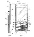
- Figure 6 is a first side view of the portable electronic device of Figure 2 shown in an open position
- Figure 7 is a front view of the portable electronic device of Figure 6 ;
- Figure 8 is a second side view of the portable electronic device of Figure 6 ;
- Figure 9 is a back view of the portable electronic device of Figure 6 ;
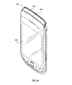
- Figure 10 is a perspective view of the portable electronic device of Figure 2 ;
- Figure 11 is a perspective view of the portable electronic device of Figure 6 ;
- Figure 12 is a back perspective view of an upper housing of the portable electronic device
- Figure 13 is a back perspective view of a portion of the upper housing of Figure 12 with a cover plate separated therefrom;
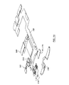
- Figure 14 is a back perspective exploded view of various components of the upper housing
- Figure 15 is a front perspective exploded view of various components of the upper housing
- Figure 16 is a front perspective exploded view of a portion of the upper housing
- Figure 17 is a front, side partial perspective view of the portable electronic device in the open position
- Figure 18 is a front, side partial perspective view of the portable electronic device in the closed position.
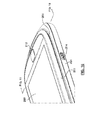
- Figure 19 is a sectional, perspective view of the portable electronic device of Figure 18 .
- the following describes a portable electronic device that includes a lower housing and an upper housing slidable relative to the lower housing between closed and open positions.
- a primary flex connector electrically connects the lower and upper housings.
- the upper housing includes an auxiliary input device and a secondary flex connector for the auxiliary input device.
- Figure 1 shows a simplified block diagram of components including internal components of a portable electronic device 100 according to one embodiment.
- Figure 1 is exemplary only, and those persons skilled in the art will appreciate the additional elements and modifications necessary to make the portable electronic device 100 work in particular network environments.
- the portable electronic device 100 includes multiple components such as a processor 102 that controls the operations of the portable electronic device 100. Communication functions, including data communications, voice communications, or both can be performed through a communication subsystem 104. Data received by the portable electronic device 100 is decompressed and decrypted by a decoder 106. The communication subsystem 104 receives messages from and sends messages to a wireless network 150.
- the wireless network 150 can be any type of wireless network, including, but not limited to, data-centric wireless networks, voice-centric wireless networks, and dual-mode networks that support both voice and data communications over the same physical base stations.
- the portable electronic device 100 can be a battery-powered device and as shown includes a battery interface 142 for receiving one or more rechargeable batteries 144.
- the processor 102 also interacts with additional subsystems such as a Random Access Memory (RAM) 108, a flash memory 110, a display 112 with a touch-sensitive overlay 114 connected to an electronic controller 116 that together comprise a touch-sensitive display 118, an actuator assembly 120, one or more optional force sensors 122, an auxiliary input/output (I/O) subsystem 124, a data port 126, a speaker 128, a microphone 130, short-range communications 132 and other device subsystems 134.
- RAM Random Access Memory
- flash memory 110 a flash memory 110
- display 112 with a touch-sensitive overlay 114 connected to an electronic controller 116 that together comprise a touch-sensitive display 118, an actuator assembly 120, one or more optional force sensors 122, an auxiliary input/output (I/O) subsystem 124, a data port 126, a speaker 128, a microphone 130, short-range communications 132 and other device subsystems 134.
- I/O auxiliary input/output
- User-interaction with the graphical user interface can be performed through the touch-sensitive overlay 114.
- the processor 102 interacts with the touch-sensitive overlay 114 via the electronic controller 116.
- Information such as text, characters, symbols, images, icons, and other items that can be displayed or rendered on a portable electronic device, is displayed on the touch-sensitive display 118 via the processor 102.
- the processor 102 can also interact with an accelerometer 136 as shown in Figure 1 .
- the accelerometer 136 can include a cantilever beam with a proof mass and suitable deflection sensing circuitry.
- the accelerometer 136 can be utilized for detecting direction of gravitational forces or gravity-induced reaction forces.
- the portable electronic device 100 can use a Subscriber Identity Module or a Removable User Identity Module (SIM/RUIM) card 138 inserted into a SIM/RUIM interface 140 for communication with a network such as the wireless network 150.
- SIM/RUIM Removable User Identity Module
- user identification information can be programmed into the flash memory 110.
- the portable electronic device 100 also includes an operating system 146 and software components 148 that are executed by the processor 102 and which can be stored in a persistent store such as the flash memory 110. Additional applications can be loaded onto the portable electronic device 100 through the wireless network 150, the auxiliary I/O subsystem 124, the data port 126, the short-range communications subsystem 132, or any other suitable device subsystem 134.
- a received signal such as a text message, an e-mail message, or web page download is processed by the communication subsystem 104 and input to the processor 102.
- the processor 102 then processes the received signal for output to the display 112 or alternatively to the auxiliary I/O subsystem 124.
- a subscriber can also compose data items, such as e-mail messages, for example, which can be transmitted over the wireless network 150 through the communication subsystem 104.
- the overall operation of the portable electronic device 100 is similar.
- the speaker 128 outputs audible information converted from electrical signals, and the microphone 130 converts audible information into electrical signals for processing.
- the portable electronic device 200 is commonly referred to as a "slider" style device and includes an upper housing 202 (or sliding portion) and a rear, lower housing 204 (or base portion).
- the upper housing 202 and lower housing 204 are coupled together, and the upper housing 202 is slidable relative to the lower housing 204 in a first linear direction between a closed position (e.g., as shown in Figure 2 ) and an open position (e.g., as shown in Figure 6 ).
- the portable electronic device 200 is generally taller than it is wide. In such examples, as the portable electronic device 200 moves between the closed and open positions, the upper housing 202 is moving relative to the lower housing 204 generally parallel to a longitudinal axis of the portable electronic device 200.
- the upper housing 202 generally includes a display 206, which can be an LCD display and which can have touch screen capabilities.
- the display 206 could be the same as or similar to the display 118 as generally described above.
- the display 206 can be a touch-sensitive display.
- the touch-sensitive display can be a capacitive touch-sensitive display, for example, and a user's touch on the touch-sensitive display can be determined by determining an X and Y location of the touch, with the X location determined by a signal generated as a result of capacitive coupling with a touch sensor layer and the Y location determined by the signal generated as a result of capacitive coupling with another touch sensor layer.
- Each of the touch-sensor layers provides a signal to a controller that represents the respective X and Y touch location values.
- a feature such as a virtual button or other feature displayed on the touch-sensitive display can be selected by a mapping of the touch location to a feature on the touch-sensitive display.
- each of the upper housing 202 and lower housing 204 can include one or more input apparatus, such as navigation keys or buttons, a physical or virtual keyboard, a trackpad, trackball, multimedia keys, etc.
- input apparatus such as navigation keys or buttons, a physical or virtual keyboard, a trackpad, trackball, multimedia keys, etc.
- the upper housing 202 as shown includes an auxiliary input device 212 that responds to user interaction, and which can be used for navigating around the display 206, to select objects on the display 206, or for other purposes.
- the auxiliary input device 212 can act as a cursor navigational tool and can be exteriorly located upon a front 203 of the upper housing 202.
- the front location of the auxiliary input device 212 is advantageous because it makes the tool easily thumb-actuatable when the device is in both the open and closed positions.
- auxiliary input device 212 can provide for relatively fine navigation control, for example, as compared with the touch sense capabilities of the display 206.
- the user can quickly and easily switch thumb position to utilize the optically based user input device to scroll around the website and access relatively small links.
- the auxiliary input device 212 can consist of an optically based user input device, which can be referred to as a "trackpad".
- the optically based user input device can be utilized to instruct two-dimensional screen cursor movement in substantially any direction, as well as act as an actuator when the optically based user input device is depressed like a button.
- the auxiliary input device 212 can be a mechanical device that responds to user interaction (e.g., a trackball).
- the display 206 and the auxiliary input device 212 are generally disposed on the front 203 of the upper housing 202 and exposed for user accessibility when the portable electronic device 200 is in either of the open or closed positions.
- the upper housing 202 can also include other input devices, such as a dedicated phone application button, a dedicated "disconnect call” button, a home screen button, etc.
- these input devices include optical sensors, mechanical buttons, or both.
- the upper housing 202 can include a navigation row 240 including a plurality of navigation keys 234 adjacent to the auxiliary input device 212.
- the portable electronic device 200 can be configured to send and receive voice communications such as mobile telephone calls.
- two call keys 230, 238 (“outer keys") are provided in the navigation row 240 at the outer ends of the navigation row 240.
- One of the two call keys is a call initiation key 230 and the other is a call termination key 238.
- the navigation row 240 also includes another pair of keys 232, 236 (“flanking keys") that are located immediately adjacent to the auxiliary input device 212.
- One is a menu call-up key 232 and the other is an escape or back key 236.
- the menu call-up key 232 can be used to bring up a menu on the display 206 and the escape key 236 can be used to return to the previous screen or previous menu selection.
- the functions of the call keys and the menu keys may, of course, be provided by buttons that are located elsewhere on the device, with different functions assigned to the outer keys and the flanking keys.
- the lower housing 204 can include various buttons and other controls, such as buttons 208 and 210, and which could be used for navigation, to control volume or for other purposes.
- the lower housing 204 could also include one or more application buttons 211 that can be used to automatically launch a particular application on the portable electronic device 200 (e.g., a camera application, a phone application, etc.).
- the button 211 can be configurable by a user (e.g., the user can be able to select the particular application launched by the button 211).
- the lower housing 204 could also include one or more input or output ports (e.g., I/O ports), such as a microUSB port 214 (and which could be similar to or the same as data port 126).
- I/O ports e.g., I/O ports
- the port 214 can be used for data communication with the portable electronic device 200, for charging of a battery (not shown, but which could for example be battery 144) on the device 200 or for both.
- the lower housing 204 can also include a battery cover 216 for covering the battery (not shown).
- the battery cover 216 can be removable. In other embodiments, the battery cover 216 can be permanently fixed to the device.
- the lower housing 204 can also include an audio jack 217.
- the audio jack 217 can be used to couple the portable electronic device 200 to a speaker, a microphone, or both, for example for use in voice communication.
- the keypad 220 generally includes a plurality of alphanumeric keys 222, which can be positioned in a plurality of rows and columns.
- the keys 222 can represent the alphabet and can be arranged with a standard keyboard layout (e.g., QWERTY, QWERTZ, DVORAK, etc.).
- the keypad 220 is covered by the upper housing 202.
- This can be beneficial as it can protect the keypad 220 when not in use, and can also inhibit keys from being pressed inadvertently when the user is carrying the portable electronic device 200 (e.g., in a pocket).
- the user can perform functions on the portable electronic device 200 while closed by interacting with the display 206, and/or by interacting with the buttons 208, 210, 211, the keys 230, 232, 236, 238, and the auxiliary input device 212.
- the display 206 and the auxiliary input device 212 are generally disposed on the front 203 of the upper housing 202 and exposed for user accessibility when the portable electronic device 200 is in either of the open or closed positions.
- auxiliary input device 212 is disposed near a bottom side 205 of the upper housing 202 so that, when in the open position (as shown in Figures 6 to 9 and 11 ), the auxiliary input device 212 is arranged between the display 206 and the keypad 220.
- the arrangement of the auxiliary input device 212 between the display 206 and the keypad 220 can reduce interference during keyboarding, does not block the user's view of the display 206 during use, and provides for relatively short distances for a user's thumb to travel back and forth between the display 206 (if touch-sensitive), the auxiliary input device 212 and the keypad 220 during use.
- FIG 12 illustrates an inner or rear side 248 of the upper housing 202.
- a cover plate 250 is affixed to the rear side 248 along the bottom side 205, extending generally between lateral sides 252, 254. Also shown is a portion 264 of a primary flex connector (described below), which provides electrical connectivity between the upper housing 202 and the lower housing 204.
- fasteners 256 can be used to affix the cover plate 250 to the upper housing 202.
- the cover plate 250 can be provided with tabs (not shown) and corresponding receiving slots (not shown) can be provided in the upper housing 202, the tabs and slots enabling a "snap-fit" arrangement.
- the cover plate 250 can be configured to conceal and protect one or more electrical connections housed in the upper housing 202. As shown, a first secondary flex connector 258 associated with the display 206, a second secondary flex connector 262 associated with the auxiliary input device 212 and a third secondary flex connector 260 associated with the navigation keys 230, 232, 236, 238 can be arranged directly underneath the cover plate 250.
- a primary flex connector 268 is shown in Figure 14 .
- the primary flex connector 268 provides electrical connectivity between the upper housing 202 and the lower housing 204, and can be referred to as a "dynamic" flex connector.
- Each of the secondary flex connectors 258, 260, 262 are operably connected to the primary flex connector 268 providing electrical connectivity between the upper housing 202 and the lower housing 204.
- the primary flex connector 268 includes the portion 264 that is arranged externally of the upper housing 202 for connection to the lower housing 204.
- the primary flex connector 268 also includes first and second flanking portions 270, 272.
- the first flanking portion 270 is arranged between the auxiliary input device 212 and the lateral side 252.
- the second flanking portion 272 is arranged between the auxiliary input device 212 and the lateral side 254.
- the first flanking portion 270 includes a connecting segment 274 for connection to the flex connector 262, and a connecting segment 276 for connection to the flex connector 260.
- the second flanking portion 272 includes a connecting segment 278 for connection to the flex connector 258.
- the flanking portions 270, 272 enable a relatively thin design for the upper housing 202 in which the electrical connectors are distributed between the lateral sides 252, 254, and near the bottom side 205.
- the connecting segments 274, 276, 278 are located spaced around to avoid the display 206 and the auxiliary input device 212, thus minimizing thickness of the upper housing 202.
- a thicker design for the upper housing 202 would be necessary if, for example, the connecting segments 274, 276, 278 were located directly underneath the display 206.
- the flex connector 260 includes a bridging portion that leads from the navigation keys on one side of the portable electronic device 200 (i.e. 230 and 232 as shown in Figure 16 ) to the connecting segment 276 on the other side of the portable electronic device 200.
- the bridging portion is spaced apart from the bottom side 205 to physically circumvent the auxiliary input device 212.
- the auxiliary input device 212 is arranged intermediate of the bridging portion of the flex connector 260 and the bottom side 205.
- the secondary flex connectors 258, 260, 262 and the flanking portions 270, 272 of the primary flex connector 268 are all arranged towards the bottom side 205.
- the cover plate 250 can be removable after assembly of the portable electronic device 200 to provide access to the secondary flex connectors 258, 260, 262 and the flanking portions 270, 272 of the primary flex connector 268, and/or other components, either for repairs or troubleshooting.
- the upper housing 202 includes a lens 280, a display 206, a slide housing 282, a slide plate 284, and a guide base 286.
- the guide base 286 includes c-channel structures 288 that allow the guide base 286 to slide relative to the slide plate 284.
- the guide base 286 is affixed to the lower housing 204 (not shown) enabling the upper housing 202 to slide relative thereto.
- the primary flex connector 268 can be installed onto the slide plate 284.
- connecting segments 274, 276 are facing an opposing direction as compared with the connecting segment 278.
- the connecting segment 278 faces forward because the display 206 is assembled in front of the slide plate 284, and thus the secondary flex connector 258 is arranged in front of the connecting segment 278.
- the connecting segments 274, 276 face backward to allow the secondary flex connectors 260, 262 to be connected to the connecting segments 274, 276 in back of the slide plate 284 after the lens 280, the display 206, the slide housing 282 and the slide plate 284 have been assembled into one unit.
- an interior region 290 of the cover plate 250 can provide a backing structure to support the auxiliary input device 212 for examples where the auxiliary input device 212 includes actuator functionality and can be depressed like a button.
- the cover plate 250 can include spacing elements 266 disposed on opposing lateral sides of the cover plate 250.
- the spacing elements 266 engage the lower housing 204 and serve as gap control features for maintaining a generally uniform gap between the upper housing 202 and the lower housing 204 as the upper housing 202 slides between the closed and opened positions, as shown in Figures 17 , 18 and 19 .
- the gap provided by the spacing elements 266 effectively accommodates the keypad 220, which can have a height dimension, preventing the upper portion 202 from rubbing against the keypad 220 as the upper housing 202 slides between the closed and opened positions.
- the spacing elements 266 can be configured to follow a sacrificial wearing surface 292 that is provided on the lower housing 204, disposed about a periphery of the keypad 220.
- the wearing surface 292 can be generally complementary in shape to the spacing elements 266.
Landscapes
- Engineering & Computer Science (AREA)
- Signal Processing (AREA)
- Telephone Set Structure (AREA)
Abstract
Description
- The present disclosure relates to portable electronic devices, and in particular to portable electronic devices having an upper housing slidable relative to a lower housing.
- Electronic devices, including portable electronic devices, have gained widespread use and may provide a variety of functions including, for example, telephonic, electronic text messaging and other personal information manager (PIM) application functions. Portable electronic devices can include several types of devices including mobile stations such as simple cellular phones, smart phones, Personal Digital Assistants (PDAs), tablets and laptop computers.
- Devices such as PDAs or smart phones are generally intended for handheld use and ease of portability. Smaller devices are generally desirable for portability. Smaller portable electronic devices are available in various constructions, including unibody designs, "clamshell" or "flip-phone" styles and "slider" phones.
- In an aspect of the present disclosure, a portable electronic device may comprise: a lower housing; an upper housing coupled to the lower housing and slidable relative thereto between a closed position and an open position, the upper housing including a display disposed on a front of the upper housing generally between first and second lateral sides, the upper housing including an auxiliary input device disposed on the front; and a primary flex connector adapted to electrically connect the lower and upper housings. In the present disclosure, "comprising" is to be construed as "including but not limited to" and "comprise" is to be construed as "include at least".
- The primary flex connector may comprise a first flanking portion arranged in the upper housing generally between the auxiliary input device and the first lateral side. The first flanking portion of the primary flex connector may be electrically connected to a first secondary flex connector associated with one of the display and the auxiliary input device. The primary flex connector may comprise a second flanking portion arranged in the upper housing generally between the auxiliary input device and the second lateral side. The second flanking portion of the primary flex connector may be electrically connected to a second secondary flex connector associated with one of the display and the auxiliary input device. The upper housing may comprise a plurality of navigation keys disposed on the front generally between the display and a bottom side of the upper housing. The first flanking portion of the primary flex connector may be electrically connected to a third secondary flex connector associated with the navigation keys. The navigation keys may comprise first keys arranged generally between the auxiliary input device and the first lateral side, and second keys arranged generally between the auxiliary input device and the second lateral side. The third secondary flex connector may comprise a bridging portion adapted to electrically connect the first flanking portion of the primary flex connector to the second keys of the navigation keys. The auxiliary input device may be arranged generally intermediate of the bridging portion and the bottom side of the upper housing.
- The upper housing may comprise a cover plate affixed to a rear of the upper housing along a bottom side of the upper housing generally between the first and second lateral sides. The cover plate may be removable to allow access to at least a portion of the primary flex connector. The portable electronic device may further comprise at least one secondary flex connector, wherein the cover plate may be removable to allow access to at least a portion of the secondary flex connector. The secondary flex connector may be arranged directly underneath the cover plate.
- The portable electronic device may further comprise at least one secondary flex connector adapted to electrically connect the primary flex connector to at least one of the auxiliary input device and the display.
- Other aspects and features of the teachings disclosed herein will become apparent, to those ordinarily skilled in the art, upon review of the following description of the specific examples of the present disclosure.
- Embodiments of the present disclosure will now be described, by way of example only, with reference to the attached Figures, wherein:
-
Figure 1 is a simplified block diagram of components including internal components of a portable electronic device according to one embodiment; -
Figure 2 is a first side view of a portable electronic device according to one embodiment shown in a closed position; -
Figure 3 is a front view of the portable electronic device ofFigure 2 ; -
Figure 4 is a second side view of the portable electronic device ofFigure 2 ; -
Figure 5 is a back view of the portable electronic device ofFigure 2 ; -
Figure 6 is a first side view of the portable electronic device ofFigure 2 shown in an open position; -
Figure 7 is a front view of the portable electronic device ofFigure 6 ; -
Figure 8 is a second side view of the portable electronic device ofFigure 6 ; -
Figure 9 is a back view of the portable electronic device ofFigure 6 ; -
Figure 10 is a perspective view of the portable electronic device ofFigure 2 ; -
Figure 11 is a perspective view of the portable electronic device ofFigure 6 ; -
Figure 12 is a back perspective view of an upper housing of the portable electronic device; -
Figure 13 is a back perspective view of a portion of the upper housing ofFigure 12 with a cover plate separated therefrom; -
Figure 14 is a back perspective exploded view of various components of the upper housing; -
Figure 15 is a front perspective exploded view of various components of the upper housing; -
Figure 16 is a front perspective exploded view of a portion of the upper housing; -
Figure 17 is a front, side partial perspective view of the portable electronic device in the open position; -
Figure 18 is a front, side partial perspective view of the portable electronic device in the closed position; and -
Figure 19 is a sectional, perspective view of the portable electronic device ofFigure 18 . - The following describes a portable electronic device that includes a lower housing and an upper housing slidable relative to the lower housing between closed and open positions. A primary flex connector electrically connects the lower and upper housings. The upper housing includes an auxiliary input device and a secondary flex connector for the auxiliary input device.
- It will be appreciated that for simplicity and clarity of illustration, where considered appropriate, reference numerals may be repeated among the figures to indicate corresponding or analogous elements. In addition, numerous specific details are set forth in order to provide a thorough understanding of the example embodiments described herein. However, it will be understood by those of ordinary skill in the art that the example embodiments described herein may be practiced without these specific details. In other instances, well-known methods, procedures and components have not been described in detail so as not to obscure the example embodiments described herein. Also, the description is not to be considered as limited to the scope of the example embodiments described herein.
-
Figure 1 shows a simplified block diagram of components including internal components of a portableelectronic device 100 according to one embodiment.Figure 1 is exemplary only, and those persons skilled in the art will appreciate the additional elements and modifications necessary to make the portableelectronic device 100 work in particular network environments. - The portable
electronic device 100 includes multiple components such as aprocessor 102 that controls the operations of the portableelectronic device 100. Communication functions, including data communications, voice communications, or both can be performed through acommunication subsystem 104. Data received by the portableelectronic device 100 is decompressed and decrypted by adecoder 106. Thecommunication subsystem 104 receives messages from and sends messages to awireless network 150. - The
wireless network 150 can be any type of wireless network, including, but not limited to, data-centric wireless networks, voice-centric wireless networks, and dual-mode networks that support both voice and data communications over the same physical base stations. - The portable
electronic device 100 can be a battery-powered device and as shown includes abattery interface 142 for receiving one or morerechargeable batteries 144. - The
processor 102 also interacts with additional subsystems such as a Random Access Memory (RAM) 108, aflash memory 110, adisplay 112 with a touch-sensitive overlay 114 connected to anelectronic controller 116 that together comprise a touch-sensitive display 118, anactuator assembly 120, one or moreoptional force sensors 122, an auxiliary input/output (I/O)subsystem 124, adata port 126, aspeaker 128, amicrophone 130, short-range communications 132 andother device subsystems 134. - User-interaction with the graphical user interface can be performed through the touch-
sensitive overlay 114. Theprocessor 102 interacts with the touch-sensitive overlay 114 via theelectronic controller 116. Information, such as text, characters, symbols, images, icons, and other items that can be displayed or rendered on a portable electronic device, is displayed on the touch-sensitive display 118 via theprocessor 102. - The
processor 102 can also interact with anaccelerometer 136 as shown inFigure 1 . Theaccelerometer 136 can include a cantilever beam with a proof mass and suitable deflection sensing circuitry. Theaccelerometer 136 can be utilized for detecting direction of gravitational forces or gravity-induced reaction forces. - To identify a subscriber for network access according to the present embodiment, the portable
electronic device 100 can use a Subscriber Identity Module or a Removable User Identity Module (SIM/RUIM)card 138 inserted into a SIM/RUIM interface 140 for communication with a network such as thewireless network 150. - Alternatively, user identification information can be programmed into the
flash memory 110. - The portable
electronic device 100 also includes anoperating system 146 andsoftware components 148 that are executed by theprocessor 102 and which can be stored in a persistent store such as theflash memory 110. Additional applications can be loaded onto the portableelectronic device 100 through thewireless network 150, the auxiliary I/O subsystem 124, thedata port 126, the short-range communications subsystem 132, or any othersuitable device subsystem 134. - In use, a received signal such as a text message, an e-mail message, or web page download is processed by the
communication subsystem 104 and input to theprocessor 102. Theprocessor 102 then processes the received signal for output to thedisplay 112 or alternatively to the auxiliary I/O subsystem 124. A subscriber can also compose data items, such as e-mail messages, for example, which can be transmitted over thewireless network 150 through thecommunication subsystem 104. - For voice communications, the overall operation of the portable
electronic device 100 is similar. Thespeaker 128 outputs audible information converted from electrical signals, and themicrophone 130 converts audible information into electrical signals for processing. - Turning now to
Figures 2 to 11 , illustrated generally therein is a portableelectronic device 200 according to one example. The portableelectronic device 200 is commonly referred to as a "slider" style device and includes an upper housing 202 (or sliding portion) and a rear, lower housing 204 (or base portion). Theupper housing 202 andlower housing 204 are coupled together, and theupper housing 202 is slidable relative to thelower housing 204 in a first linear direction between a closed position (e.g., as shown inFigure 2 ) and an open position (e.g., as shown inFigure 6 ). - In some examples, and as shown, the portable
electronic device 200 is generally taller than it is wide. In such examples, as the portableelectronic device 200 moves between the closed and open positions, theupper housing 202 is moving relative to thelower housing 204 generally parallel to a longitudinal axis of the portableelectronic device 200. - As shown, the
upper housing 202 generally includes adisplay 206, which can be an LCD display and which can have touch screen capabilities. In some examples, thedisplay 206 could be the same as or similar to thedisplay 118 as generally described above. - Optionally, in some examples, the
display 206 can be a touch-sensitive display. The touch-sensitive display can be a capacitive touch-sensitive display, for example, and a user's touch on the touch-sensitive display can be determined by determining an X and Y location of the touch, with the X location determined by a signal generated as a result of capacitive coupling with a touch sensor layer and the Y location determined by the signal generated as a result of capacitive coupling with another touch sensor layer. Each of the touch-sensor layers provides a signal to a controller that represents the respective X and Y touch location values. Thus, a feature such as a virtual button or other feature displayed on the touch-sensitive display can be selected by a mapping of the touch location to a feature on the touch-sensitive display. - As shown, each of the
upper housing 202 andlower housing 204 can include one or more input apparatus, such as navigation keys or buttons, a physical or virtual keyboard, a trackpad, trackball, multimedia keys, etc. - The
upper housing 202 as shown includes anauxiliary input device 212 that responds to user interaction, and which can be used for navigating around thedisplay 206, to select objects on thedisplay 206, or for other purposes. Theauxiliary input device 212 can act as a cursor navigational tool and can be exteriorly located upon afront 203 of theupper housing 202. The front location of theauxiliary input device 212 is advantageous because it makes the tool easily thumb-actuatable when the device is in both the open and closed positions. - Implementation of the
auxiliary input device 212 can provide for relatively fine navigation control, for example, as compared with the touch sense capabilities of thedisplay 206. Thus, for example, when using the touch-sensitive display 206 to navigate a website, the user can quickly and easily switch thumb position to utilize the optically based user input device to scroll around the website and access relatively small links. - In some examples, the
auxiliary input device 212 can consist of an optically based user input device, which can be referred to as a "trackpad". The optically based user input device can be utilized to instruct two-dimensional screen cursor movement in substantially any direction, as well as act as an actuator when the optically based user input device is depressed like a button. - In some other examples, the
auxiliary input device 212 can be a mechanical device that responds to user interaction (e.g., a trackball). - The
display 206 and theauxiliary input device 212 are generally disposed on thefront 203 of theupper housing 202 and exposed for user accessibility when the portableelectronic device 200 is in either of the open or closed positions. - The
upper housing 202 can also include other input devices, such as a dedicated phone application button, a dedicated "disconnect call" button, a home screen button, etc. In various embodiments, these input devices include optical sensors, mechanical buttons, or both. - For example, as shown, the
upper housing 202 can include anavigation row 240 including a plurality ofnavigation keys 234 adjacent to theauxiliary input device 212. The portableelectronic device 200 can be configured to send and receive voice communications such as mobile telephone calls. To facilitate telephone calls, twocall keys 230, 238 ("outer keys") are provided in thenavigation row 240 at the outer ends of thenavigation row 240. One of the two call keys is a call initiation key 230 and the other is acall termination key 238. Thenavigation row 240 also includes another pair ofkeys 232, 236 ("flanking keys") that are located immediately adjacent to theauxiliary input device 212. One is a menu call-upkey 232 and the other is an escape or back key 236. The menu call-upkey 232 can be used to bring up a menu on thedisplay 206 and theescape key 236 can be used to return to the previous screen or previous menu selection. The functions of the call keys and the menu keys may, of course, be provided by buttons that are located elsewhere on the device, with different functions assigned to the outer keys and the flanking keys. - Turning now to the
lower housing 204, thelower housing 204 can include various buttons and other controls, such asbuttons - The
lower housing 204 could also include one ormore application buttons 211 that can be used to automatically launch a particular application on the portable electronic device 200 (e.g., a camera application, a phone application, etc.). In some embodiments, thebutton 211 can be configurable by a user (e.g., the user can be able to select the particular application launched by the button 211). - As shown in
Figures 2 and6 , thelower housing 204 could also include one or more input or output ports (e.g., I/O ports), such as a microUSB port 214 (and which could be similar to or the same as data port 126). In some examples, theport 214 can be used for data communication with the portableelectronic device 200, for charging of a battery (not shown, but which could for example be battery 144) on thedevice 200 or for both. - As shown, the
lower housing 204 can also include abattery cover 216 for covering the battery (not shown). In some embodiments, thebattery cover 216 can be removable. In other embodiments, thebattery cover 216 can be permanently fixed to the device. - In some embodiments, the
lower housing 204 can also include anaudio jack 217. Theaudio jack 217 can be used to couple the portableelectronic device 200 to a speaker, a microphone, or both, for example for use in voice communication. - Turning now to
Figures 6 to 9 and 11 , as shown when the portableelectronic device 200 is in the open position, akeypad 220 is exposed on alower portion 218 of thelower housing 204. Thekeypad 220 generally includes a plurality ofalphanumeric keys 222, which can be positioned in a plurality of rows and columns. In some embodiments, thekeys 222 can represent the alphabet and can be arranged with a standard keyboard layout (e.g., QWERTY, QWERTZ, DVORAK, etc.). - As shown in
Figures 2 to 5 and 10 , when the portableelectronic device 200 is in the closed position, thekeypad 220 is covered by theupper housing 202. This can be beneficial as it can protect thekeypad 220 when not in use, and can also inhibit keys from being pressed inadvertently when the user is carrying the portable electronic device 200 (e.g., in a pocket). However, in some cases (e.g., when thedisplay 206 is a touch-sensitive display) the user can perform functions on the portableelectronic device 200 while closed by interacting with thedisplay 206, and/or by interacting with thebuttons keys auxiliary input device 212. As mentioned above, thedisplay 206 and theauxiliary input device 212 are generally disposed on thefront 203 of theupper housing 202 and exposed for user accessibility when the portableelectronic device 200 is in either of the open or closed positions. - When the portable
electronic device 200 is in the open position (as shown inFigures 6 to 9 and 11 ), thekeypad 220 is exposed for user accessibility. Furthermore,auxiliary input device 212 is disposed near abottom side 205 of theupper housing 202 so that, when in the open position (as shown inFigures 6 to 9 and 11 ), theauxiliary input device 212 is arranged between thedisplay 206 and thekeypad 220. The arrangement of theauxiliary input device 212 between thedisplay 206 and thekeypad 220 can reduce interference during keyboarding, does not block the user's view of thedisplay 206 during use, and provides for relatively short distances for a user's thumb to travel back and forth between the display 206 (if touch-sensitive), theauxiliary input device 212 and thekeypad 220 during use. - Reference is now made to
Figure 12 , which illustrates an inner orrear side 248 of theupper housing 202. Acover plate 250 is affixed to therear side 248 along thebottom side 205, extending generally betweenlateral sides portion 264 of a primary flex connector (described below), which provides electrical connectivity between theupper housing 202 and thelower housing 204. - Referring to
Figure 13 ,fasteners 256 can be used to affix thecover plate 250 to theupper housing 202. Of course other means of affixing thecover plate 250 are possible. For example, thecover plate 250 can be provided with tabs (not shown) and corresponding receiving slots (not shown) can be provided in theupper housing 202, the tabs and slots enabling a "snap-fit" arrangement. - The
cover plate 250 can be configured to conceal and protect one or more electrical connections housed in theupper housing 202. As shown, a firstsecondary flex connector 258 associated with thedisplay 206, a secondsecondary flex connector 262 associated with theauxiliary input device 212 and a thirdsecondary flex connector 260 associated with thenavigation keys cover plate 250. - A
primary flex connector 268 is shown inFigure 14 . Theprimary flex connector 268 provides electrical connectivity between theupper housing 202 and thelower housing 204, and can be referred to as a "dynamic" flex connector. Each of thesecondary flex connectors primary flex connector 268 providing electrical connectivity between theupper housing 202 and thelower housing 204. - Referring to
Figures 12 ,13 and14 , theprimary flex connector 268 includes theportion 264 that is arranged externally of theupper housing 202 for connection to thelower housing 204. Theprimary flex connector 268 also includes first and second flankingportions 270, 272. Thefirst flanking portion 270 is arranged between theauxiliary input device 212 and thelateral side 252. The second flanking portion 272 is arranged between theauxiliary input device 212 and thelateral side 254. Thefirst flanking portion 270 includes a connectingsegment 274 for connection to theflex connector 262, and a connectingsegment 276 for connection to theflex connector 260. The second flanking portion 272 includes a connectingsegment 278 for connection to theflex connector 258. - The flanking
portions 270, 272 enable a relatively thin design for theupper housing 202 in which the electrical connectors are distributed between thelateral sides bottom side 205. In other words, the connectingsegments display 206 and theauxiliary input device 212, thus minimizing thickness of theupper housing 202. A thicker design for theupper housing 202 would be necessary if, for example, the connectingsegments display 206. - Furthermore, as shown in
Figures 13 and14 , theflex connector 260 includes a bridging portion that leads from the navigation keys on one side of the portable electronic device 200 (i.e. 230 and 232 as shown inFigure 16 ) to the connectingsegment 276 on the other side of the portableelectronic device 200. The bridging portion is spaced apart from thebottom side 205 to physically circumvent theauxiliary input device 212. In other words, theauxiliary input device 212 is arranged intermediate of the bridging portion of theflex connector 260 and thebottom side 205. - It is advantageous that the
secondary flex connectors portions 270, 272 of theprimary flex connector 268 are all arranged towards thebottom side 205. In some examples, thecover plate 250 can be removable after assembly of the portableelectronic device 200 to provide access to thesecondary flex connectors portions 270, 272 of theprimary flex connector 268, and/or other components, either for repairs or troubleshooting. - Referring to
Figure 15 , and with reference back toFigure 12 , in some examples theupper housing 202 includes alens 280, adisplay 206, aslide housing 282, aslide plate 284, and aguide base 286. Theguide base 286 includes c-channel structures 288 that allow theguide base 286 to slide relative to theslide plate 284. Theguide base 286 is affixed to the lower housing 204 (not shown) enabling theupper housing 202 to slide relative thereto. As shown, theprimary flex connector 268 can be installed onto theslide plate 284. - It can be seen in
Figures 14 and15 that the connectingsegments segment 278. The connectingsegment 278 faces forward because thedisplay 206 is assembled in front of theslide plate 284, and thus thesecondary flex connector 258 is arranged in front of the connectingsegment 278. On the other hand, the connectingsegments secondary flex connectors segments slide plate 284 after thelens 280, thedisplay 206, theslide housing 282 and theslide plate 284 have been assembled into one unit. - As shown best in
Figure 16 , aninterior region 290 of thecover plate 250 can provide a backing structure to support theauxiliary input device 212 for examples where theauxiliary input device 212 includes actuator functionality and can be depressed like a button. - As shown in
Figure 13 , thecover plate 250 can includespacing elements 266 disposed on opposing lateral sides of thecover plate 250. Thespacing elements 266 engage thelower housing 204 and serve as gap control features for maintaining a generally uniform gap between theupper housing 202 and thelower housing 204 as theupper housing 202 slides between the closed and opened positions, as shown inFigures 17 ,18 and19 . The gap provided by thespacing elements 266 effectively accommodates thekeypad 220, which can have a height dimension, preventing theupper portion 202 from rubbing against thekeypad 220 as theupper housing 202 slides between the closed and opened positions. Thespacing elements 266 can be configured to follow a sacrificial wearingsurface 292 that is provided on thelower housing 204, disposed about a periphery of thekeypad 220. The wearingsurface 292 can be generally complementary in shape to thespacing elements 266. - While the above description provides examples of one or more processes or apparatuses, it will be appreciated that other processes or apparatuses may be within the scope of the accompanying claims.
Claims (15)
- A portable electronic device (200), comprising:a lower housing (204);an upper housing (202) coupled to the lower housing (204) and slidable relative thereto between a closed position and an open position, the upper housing (202) comprising a display (206) disposed on a front (203) of the upper housing (202) generally between first and second lateral sides (252, 254), the upper housing (202) comprising an auxiliary input device (212) disposed on the front (203); anda primary flex connector (268) adapted to electrically connect the lower and upper housings (204, 202).
- The device of claim 1, wherein the primary flex connector (268) comprises a first flanking portion (270) arranged in the upper housing (202) generally between the auxiliary input device (212) and the first lateral side (252).
- The device of claim 2, wherein the first flanking portion (270) of the primary flex connector (268) is electrically connected to a first secondary flex connector (258) associated with one of the display (206) and the auxiliary input device (212).
- The device of claim 1, 2 or 3, wherein the primary flex connector (268) comprises a second flanking portion (272) arranged in the upper housing (202) generally between the auxiliary input device (212) and the second lateral side (254).
- The device of claim 4, wherein the second flanking portion (272) of the primary flex connector (268) is electrically connected to a second secondary flex connector (262) associated with one of the display (206) and the auxiliary input device (212).
- The device of any preceding claim, wherein the upper housing (202) comprises a plurality of navigation keys (230, 232, 236, 238) disposed on the front (203) generally between the display (206) and a bottom side (205) of the upper housing (202).
- The device of claim 6, wherein the first flanking portion (270) of the primary flex connector (268) is electrically connected to a third secondary flex connector (260) associated with the navigation keys (230, 232, 236, 238).
- The device of claim 7, wherein the navigation keys (230, 232, 236, 238) comprise first keys (230, 232) arranged generally between the auxiliary input device (212) and the first lateral side (252), and second keys (236, 238) arranged generally between the auxiliary input device (212) and the second lateral side (254).
- The device of claim 8, wherein the third secondary flex connector (260) comprises a bridging portion adapted to electrically connect the first flanking portion (270) of the primary flex connector (268) to the second keys (236, 238) of the navigation keys (230, 232, 236, 238).
- The device of claim 9, wherein the auxiliary input device (212) is arranged generally intermediate of the bridging portion and the bottom side (205) of the upper housing (202).
- The device of any preceding claim, wherein the upper housing (202) comprises a cover plate (250) affixed to a rear (248) of the upper housing (202) along a bottom side (205) of the upper housing (202) generally between the first and second lateral sides (252, 254).
- The device of claim 11, wherein the cover plate (250) is removable to allow access to at least a portion of the primary flex connector (268).
- The device of claim 11 or 12, comprising at least one secondary flex connector (258, 262, 260), wherein the cover plate (250) is removable to allow access to at least a portion of the secondary flex connector (258, 262, 260).
- The device of claim 13, wherein the secondary flex connector (258, 262, 260) is arranged directly underneath the cover plate (250).
- The device of any preceding claim, comprising at least one secondary flex connector (258, 262, 260) adapted to electrically connect the primary flex connector (268) to at least one of the auxiliary input device (212) and the display (206).
Applications Claiming Priority (1)
| Application Number | Priority Date | Filing Date | Title |
|---|---|---|---|
| US30469310P | 2010-02-15 | 2010-02-15 |
Publications (2)
| Publication Number | Publication Date |
|---|---|
| EP2365682A1 true EP2365682A1 (en) | 2011-09-14 |
| EP2365682B1 EP2365682B1 (en) | 2012-07-25 |
Family
ID=43799676
Family Applications (1)
| Application Number | Title | Priority Date | Filing Date |
|---|---|---|---|
| EP11152957A Active EP2365682B1 (en) | 2010-02-15 | 2011-02-01 | Portable electronic device with auxiliary input device and flex connector therefor |
Country Status (3)
| Country | Link |
|---|---|
| US (1) | US9020570B2 (en) |
| EP (1) | EP2365682B1 (en) |
| CA (1) | CA2731087C (en) |
Citations (1)
| Publication number | Priority date | Publication date | Assignee | Title |
|---|---|---|---|---|
| WO2009113124A1 (en) * | 2008-03-11 | 2009-09-17 | 住友ベークライト株式会社 | Connector unit and electronic device |
Family Cites Families (15)
| Publication number | Priority date | Publication date | Assignee | Title |
|---|---|---|---|---|
| KR100630559B1 (en) | 2004-08-10 | 2006-09-29 | 주식회사 팬택 | Slim Mobile Communication Terminal |
| US8232969B2 (en) * | 2004-10-08 | 2012-07-31 | Immersion Corporation | Haptic feedback for button and scrolling action simulation in touch input devices |
| KR100640500B1 (en) * | 2005-07-20 | 2006-10-30 | 삼성전자주식회사 | Sliding swing type portable terminal for multimedia |
| KR100810263B1 (en) * | 2005-10-11 | 2008-03-07 | 삼성전자주식회사 | Key pad for portable terminal and sliding module and flexible printed circuit board thereof |
| KR100703466B1 (en) * | 2006-04-03 | 2007-04-03 | 삼성전자주식회사 | Slim portable terminal |
| US20080119248A1 (en) * | 2006-11-21 | 2008-05-22 | Nokia Corporation | Music control key |
| KR101155259B1 (en) * | 2006-12-15 | 2012-06-13 | 엘지전자 주식회사 | Wireless communication terminal and method for selecting an operation mode thereof |
| US7822446B2 (en) * | 2007-02-09 | 2010-10-26 | Nokia Corporation | Portable electronic device with compliant sliding hinge |
| EP2144423A4 (en) * | 2007-04-25 | 2012-05-16 | Nec Corp | Rotation type portable terminal |
| US20090170574A1 (en) * | 2007-12-28 | 2009-07-02 | Motorola Inc | Methods and slider form factor devices with contiguous surfaces when open |
| US8294670B2 (en) | 2008-02-05 | 2012-10-23 | Research In Motion Limited | Optically based input mechanism for a handheld electronic communication device |
| US8108014B2 (en) * | 2008-03-14 | 2012-01-31 | Sony Ericsson Mobile Communications Ab | Portable communication device including a spring lift assembly |
| US8107229B2 (en) * | 2008-03-14 | 2012-01-31 | Sony Ericsson Mobile Communications Ab | Portable communication device having a printed circuit board slider hinge assembly |
| CN101754622B (en) * | 2008-12-15 | 2012-09-19 | 深圳富泰宏精密工业有限公司 | portable electronic device |
| US8244317B2 (en) * | 2009-06-08 | 2012-08-14 | Motorola Mobility Llc | Indicator shelf for portable electronic device |
-
2011
- 2011-02-01 EP EP11152957A patent/EP2365682B1/en active Active
- 2011-02-01 US US13/019,008 patent/US9020570B2/en active Active
- 2011-02-01 CA CA2731087A patent/CA2731087C/en active Active
Patent Citations (2)
| Publication number | Priority date | Publication date | Assignee | Title |
|---|---|---|---|---|
| WO2009113124A1 (en) * | 2008-03-11 | 2009-09-17 | 住友ベークライト株式会社 | Connector unit and electronic device |
| US20100331060A1 (en) * | 2008-03-11 | 2010-12-30 | Sumitomo Bakelite Co. Ltd | Connector unit and electronic equipment |
Also Published As
| Publication number | Publication date |
|---|---|
| US20110201390A1 (en) | 2011-08-18 |
| US9020570B2 (en) | 2015-04-28 |
| CA2731087A1 (en) | 2011-08-15 |
| CA2731087C (en) | 2015-01-27 |
| EP2365682B1 (en) | 2012-07-25 |
Similar Documents
| Publication | Publication Date | Title |
|---|---|---|
| EP2360551B1 (en) | Portable electronic device with upper housing and cover plate therefor | |
| EP2387212A1 (en) | Handheld electronic communication device having sliding display | |
| US8965465B2 (en) | Portable electronic device having at least one of resonator and shield | |
| US10061394B2 (en) | Electronic device including keypad with keys having a ridged surface profile | |
| CA2731087C (en) | Portable electronic device with auxiliary input device and flex connector therefor | |
| CA2731763C (en) | Portable electronic device with upper housing and cover plate therefor | |
| US8638556B2 (en) | Electronic device including a front bezel operable to secure the device together | |
| CA2730825C (en) | Portable electronic device with battery cover and locking mechanism therefor | |
| EP2537079B1 (en) | Portable slidable electronic device having a dynamic flex alignment scheme and methods of assembling same | |
| EP2498478B1 (en) | Slidable portable electronic device with keypad portion adapted for covering display | |
| CA2692875A1 (en) | Electronic device including breakthrough antenna |
Legal Events
| Date | Code | Title | Description |
|---|---|---|---|
| PUAI | Public reference made under article 153(3) epc to a published international application that has entered the european phase |
Free format text: ORIGINAL CODE: 0009012 |
|
| 17P | Request for examination filed |
Effective date: 20110201 |
|
| AK | Designated contracting states |
Kind code of ref document: A1 Designated state(s): AL AT BE BG CH CY CZ DE DK EE ES FI FR GB GR HR HU IE IS IT LI LT LU LV MC MK MT NL NO PL PT RO RS SE SI SK SM TR |
|
| AX | Request for extension of the european patent |
Extension state: BA ME |
|
| GRAP | Despatch of communication of intention to grant a patent |
Free format text: ORIGINAL CODE: EPIDOSNIGR1 |
|
| GRAS | Grant fee paid |
Free format text: ORIGINAL CODE: EPIDOSNIGR3 |
|
| GRAA | (expected) grant |
Free format text: ORIGINAL CODE: 0009210 |
|
| AK | Designated contracting states |
Kind code of ref document: B1 Designated state(s): AL AT BE BG CH CY CZ DE DK EE ES FI FR GB GR HR HU IE IS IT LI LT LU LV MC MK MT NL NO PL PT RO RS SE SI SK SM TR |
|
| REG | Reference to a national code |
Ref country code: GB Ref legal event code: FG4D |
|
| REG | Reference to a national code |
Ref country code: CH Ref legal event code: EP |
|
| REG | Reference to a national code |
Ref country code: AT Ref legal event code: REF Ref document number: 568103 Country of ref document: AT Kind code of ref document: T Effective date: 20120815 Ref country code: IE Ref legal event code: FG4D |
|
| REG | Reference to a national code |
Ref country code: DE Ref legal event code: R096 Ref document number: 602011000120 Country of ref document: DE Effective date: 20120920 |
|
| REG | Reference to a national code |
Ref country code: NL Ref legal event code: T3 |
|
| REG | Reference to a national code |
Ref country code: AT Ref legal event code: MK05 Ref document number: 568103 Country of ref document: AT Kind code of ref document: T Effective date: 20120725 |
|
| REG | Reference to a national code |
Ref country code: LT Ref legal event code: MG4D Effective date: 20120725 |
|
| PG25 | Lapsed in a contracting state [announced via postgrant information from national office to epo] |
Ref country code: IS Free format text: LAPSE BECAUSE OF FAILURE TO SUBMIT A TRANSLATION OF THE DESCRIPTION OR TO PAY THE FEE WITHIN THE PRESCRIBED TIME-LIMIT Effective date: 20121125 Ref country code: BE Free format text: LAPSE BECAUSE OF FAILURE TO SUBMIT A TRANSLATION OF THE DESCRIPTION OR TO PAY THE FEE WITHIN THE PRESCRIBED TIME-LIMIT Effective date: 20120725 Ref country code: FI Free format text: LAPSE BECAUSE OF FAILURE TO SUBMIT A TRANSLATION OF THE DESCRIPTION OR TO PAY THE FEE WITHIN THE PRESCRIBED TIME-LIMIT Effective date: 20120725 Ref country code: AT Free format text: LAPSE BECAUSE OF FAILURE TO SUBMIT A TRANSLATION OF THE DESCRIPTION OR TO PAY THE FEE WITHIN THE PRESCRIBED TIME-LIMIT Effective date: 20120725 Ref country code: NO Free format text: LAPSE BECAUSE OF FAILURE TO SUBMIT A TRANSLATION OF THE DESCRIPTION OR TO PAY THE FEE WITHIN THE PRESCRIBED TIME-LIMIT Effective date: 20121025 Ref country code: LT Free format text: LAPSE BECAUSE OF FAILURE TO SUBMIT A TRANSLATION OF THE DESCRIPTION OR TO PAY THE FEE WITHIN THE PRESCRIBED TIME-LIMIT Effective date: 20120725 Ref country code: HR Free format text: LAPSE BECAUSE OF FAILURE TO SUBMIT A TRANSLATION OF THE DESCRIPTION OR TO PAY THE FEE WITHIN THE PRESCRIBED TIME-LIMIT Effective date: 20120725 Ref country code: CY Free format text: LAPSE BECAUSE OF FAILURE TO SUBMIT A TRANSLATION OF THE DESCRIPTION OR TO PAY THE FEE WITHIN THE PRESCRIBED TIME-LIMIT Effective date: 20120725 |
|
| PG25 | Lapsed in a contracting state [announced via postgrant information from national office to epo] |
Ref country code: LV Free format text: LAPSE BECAUSE OF FAILURE TO SUBMIT A TRANSLATION OF THE DESCRIPTION OR TO PAY THE FEE WITHIN THE PRESCRIBED TIME-LIMIT Effective date: 20120725 Ref country code: GR Free format text: LAPSE BECAUSE OF FAILURE TO SUBMIT A TRANSLATION OF THE DESCRIPTION OR TO PAY THE FEE WITHIN THE PRESCRIBED TIME-LIMIT Effective date: 20121026 Ref country code: SI Free format text: LAPSE BECAUSE OF FAILURE TO SUBMIT A TRANSLATION OF THE DESCRIPTION OR TO PAY THE FEE WITHIN THE PRESCRIBED TIME-LIMIT Effective date: 20120725 Ref country code: PL Free format text: LAPSE BECAUSE OF FAILURE TO SUBMIT A TRANSLATION OF THE DESCRIPTION OR TO PAY THE FEE WITHIN THE PRESCRIBED TIME-LIMIT Effective date: 20120725 Ref country code: SE Free format text: LAPSE BECAUSE OF FAILURE TO SUBMIT A TRANSLATION OF THE DESCRIPTION OR TO PAY THE FEE WITHIN THE PRESCRIBED TIME-LIMIT Effective date: 20120725 Ref country code: PT Free format text: LAPSE BECAUSE OF FAILURE TO SUBMIT A TRANSLATION OF THE DESCRIPTION OR TO PAY THE FEE WITHIN THE PRESCRIBED TIME-LIMIT Effective date: 20121126 |
|
| PG25 | Lapsed in a contracting state [announced via postgrant information from national office to epo] |
Ref country code: RO Free format text: LAPSE BECAUSE OF FAILURE TO SUBMIT A TRANSLATION OF THE DESCRIPTION OR TO PAY THE FEE WITHIN THE PRESCRIBED TIME-LIMIT Effective date: 20120725 Ref country code: DK Free format text: LAPSE BECAUSE OF FAILURE TO SUBMIT A TRANSLATION OF THE DESCRIPTION OR TO PAY THE FEE WITHIN THE PRESCRIBED TIME-LIMIT Effective date: 20120725 Ref country code: EE Free format text: LAPSE BECAUSE OF FAILURE TO SUBMIT A TRANSLATION OF THE DESCRIPTION OR TO PAY THE FEE WITHIN THE PRESCRIBED TIME-LIMIT Effective date: 20120725 Ref country code: CZ Free format text: LAPSE BECAUSE OF FAILURE TO SUBMIT A TRANSLATION OF THE DESCRIPTION OR TO PAY THE FEE WITHIN THE PRESCRIBED TIME-LIMIT Effective date: 20120725 |
|
| PG25 | Lapsed in a contracting state [announced via postgrant information from national office to epo] |
Ref country code: SK Free format text: LAPSE BECAUSE OF FAILURE TO SUBMIT A TRANSLATION OF THE DESCRIPTION OR TO PAY THE FEE WITHIN THE PRESCRIBED TIME-LIMIT Effective date: 20120725 Ref country code: IT Free format text: LAPSE BECAUSE OF FAILURE TO SUBMIT A TRANSLATION OF THE DESCRIPTION OR TO PAY THE FEE WITHIN THE PRESCRIBED TIME-LIMIT Effective date: 20120725 |
|
| PLBE | No opposition filed within time limit |
Free format text: ORIGINAL CODE: 0009261 |
|
| STAA | Information on the status of an ep patent application or granted ep patent |
Free format text: STATUS: NO OPPOSITION FILED WITHIN TIME LIMIT |
|
| 26N | No opposition filed |
Effective date: 20130426 |
|
| PG25 | Lapsed in a contracting state [announced via postgrant information from national office to epo] |
Ref country code: RS Free format text: LAPSE BECAUSE OF FAILURE TO SUBMIT A TRANSLATION OF THE DESCRIPTION OR TO PAY THE FEE WITHIN THE PRESCRIBED TIME-LIMIT Effective date: 20120725 Ref country code: BG Free format text: LAPSE BECAUSE OF FAILURE TO SUBMIT A TRANSLATION OF THE DESCRIPTION OR TO PAY THE FEE WITHIN THE PRESCRIBED TIME-LIMIT Effective date: 20121025 |
|
| REG | Reference to a national code |
Ref country code: DE Ref legal event code: R097 Ref document number: 602011000120 Country of ref document: DE Effective date: 20130426 |
|
| PG25 | Lapsed in a contracting state [announced via postgrant information from national office to epo] |
Ref country code: MC Free format text: LAPSE BECAUSE OF NON-PAYMENT OF DUE FEES Effective date: 20130228 |
|
| PG25 | Lapsed in a contracting state [announced via postgrant information from national office to epo] |
Ref country code: ES Free format text: LAPSE BECAUSE OF FAILURE TO SUBMIT A TRANSLATION OF THE DESCRIPTION OR TO PAY THE FEE WITHIN THE PRESCRIBED TIME-LIMIT Effective date: 20121105 |
|
| REG | Reference to a national code |
Ref country code: IE Ref legal event code: MM4A |
|
| PG25 | Lapsed in a contracting state [announced via postgrant information from national office to epo] |
Ref country code: IE Free format text: LAPSE BECAUSE OF NON-PAYMENT OF DUE FEES Effective date: 20130201 Ref country code: AL Free format text: LAPSE BECAUSE OF FAILURE TO SUBMIT A TRANSLATION OF THE DESCRIPTION OR TO PAY THE FEE WITHIN THE PRESCRIBED TIME-LIMIT Effective date: 20120725 |
|
| PG25 | Lapsed in a contracting state [announced via postgrant information from national office to epo] |
Ref country code: MT Free format text: LAPSE BECAUSE OF FAILURE TO SUBMIT A TRANSLATION OF THE DESCRIPTION OR TO PAY THE FEE WITHIN THE PRESCRIBED TIME-LIMIT Effective date: 20120725 |
|
| REG | Reference to a national code |
Ref country code: DE Ref legal event code: R082 Ref document number: 602011000120 Country of ref document: DE Representative=s name: MERH-IP MATIAS ERNY REICHL HOFFMANN, DE |
|
| REG | Reference to a national code |
Ref country code: CH Ref legal event code: PL |
|
| PG25 | Lapsed in a contracting state [announced via postgrant information from national office to epo] |
Ref country code: LI Free format text: LAPSE BECAUSE OF NON-PAYMENT OF DUE FEES Effective date: 20140228 Ref country code: CH Free format text: LAPSE BECAUSE OF NON-PAYMENT OF DUE FEES Effective date: 20140228 |
|
| REG | Reference to a national code |
Ref country code: DE Ref legal event code: R081 Ref document number: 602011000120 Country of ref document: DE Owner name: BLACKBERRY LIMITED, WATERLOO, CA Free format text: FORMER OWNER: RESEARCH IN MOTION LIMITED, WATERLOO, ONTARIO, CA Effective date: 20140926 Ref country code: DE Ref legal event code: R082 Ref document number: 602011000120 Country of ref document: DE Representative=s name: MERH-IP MATIAS ERNY REICHL HOFFMANN, DE Effective date: 20140926 Ref country code: DE Ref legal event code: R082 Ref document number: 602011000120 Country of ref document: DE Representative=s name: MERH-IP MATIAS ERNY REICHL HOFFMANN PATENTANWA, DE Effective date: 20140926 |
|
| PG25 | Lapsed in a contracting state [announced via postgrant information from national office to epo] |
Ref country code: SM Free format text: LAPSE BECAUSE OF FAILURE TO SUBMIT A TRANSLATION OF THE DESCRIPTION OR TO PAY THE FEE WITHIN THE PRESCRIBED TIME-LIMIT Effective date: 20120725 |
|
| PG25 | Lapsed in a contracting state [announced via postgrant information from national office to epo] |
Ref country code: TR Free format text: LAPSE BECAUSE OF FAILURE TO SUBMIT A TRANSLATION OF THE DESCRIPTION OR TO PAY THE FEE WITHIN THE PRESCRIBED TIME-LIMIT Effective date: 20120725 |
|
| PG25 | Lapsed in a contracting state [announced via postgrant information from national office to epo] |
Ref country code: HU Free format text: LAPSE BECAUSE OF FAILURE TO SUBMIT A TRANSLATION OF THE DESCRIPTION OR TO PAY THE FEE WITHIN THE PRESCRIBED TIME-LIMIT; INVALID AB INITIO Effective date: 20110201 Ref country code: LU Free format text: LAPSE BECAUSE OF NON-PAYMENT OF DUE FEES Effective date: 20130201 Ref country code: MK Free format text: LAPSE BECAUSE OF FAILURE TO SUBMIT A TRANSLATION OF THE DESCRIPTION OR TO PAY THE FEE WITHIN THE PRESCRIBED TIME-LIMIT Effective date: 20120725 |
|
| REG | Reference to a national code |
Ref country code: FR Ref legal event code: PLFP Year of fee payment: 6 |
|
| REG | Reference to a national code |
Ref country code: FR Ref legal event code: PLFP Year of fee payment: 7 |
|
| REG | Reference to a national code |
Ref country code: FR Ref legal event code: PLFP Year of fee payment: 8 |
|
| REG | Reference to a national code |
Ref country code: DE Ref legal event code: R082 Ref document number: 602011000120 Country of ref document: DE Ref country code: DE Ref legal event code: R081 Ref document number: 602011000120 Country of ref document: DE Owner name: MALIKIE INNOVATIONS LTD., IE Free format text: FORMER OWNER: BLACKBERRY LIMITED, WATERLOO, ONTARIO, CA |
|
| PGFP | Annual fee paid to national office [announced via postgrant information from national office to epo] |
Ref country code: NL Payment date: 20260220 Year of fee payment: 16 |
|
| PGFP | Annual fee paid to national office [announced via postgrant information from national office to epo] |
Ref country code: GB Payment date: 20260223 Year of fee payment: 16 |
|
| PGFP | Annual fee paid to national office [announced via postgrant information from national office to epo] |
Ref country code: DE Payment date: 20260220 Year of fee payment: 16 |
|
| PGFP | Annual fee paid to national office [announced via postgrant information from national office to epo] |
Ref country code: FR Payment date: 20260224 Year of fee payment: 16 |