EP2365509A1 - Electrostatic relay - Google Patents
Electrostatic relay Download PDFInfo
- Publication number
- EP2365509A1 EP2365509A1 EP10189070A EP10189070A EP2365509A1 EP 2365509 A1 EP2365509 A1 EP 2365509A1 EP 10189070 A EP10189070 A EP 10189070A EP 10189070 A EP10189070 A EP 10189070A EP 2365509 A1 EP2365509 A1 EP 2365509A1
- Authority
- EP
- European Patent Office
- Prior art keywords
- fixed
- movable
- spring
- movable electrode
- electrode portion
- Prior art date
- Legal status (The legal status is an assumption and is not a legal conclusion. Google has not performed a legal analysis and makes no representation as to the accuracy of the status listed.)
- Granted
Links
Images



Classifications
-
- H—ELECTRICITY
- H01—ELECTRIC ELEMENTS
- H01H—ELECTRIC SWITCHES; RELAYS; SELECTORS; EMERGENCY PROTECTIVE DEVICES
- H01H59/00—Electrostatic relays; Electro-adhesion relays
- H01H59/0009—Electrostatic relays; Electro-adhesion relays making use of micromechanics
-
- H—ELECTRICITY
- H01—ELECTRIC ELEMENTS
- H01H—ELECTRIC SWITCHES; RELAYS; SELECTORS; EMERGENCY PROTECTIVE DEVICES
- H01H45/00—Details of relays
- H01H45/14—Terminal arrangements
-
- H—ELECTRICITY
- H01—ELECTRIC ELEMENTS
- H01H—ELECTRIC SWITCHES; RELAYS; SELECTORS; EMERGENCY PROTECTIVE DEVICES
- H01H1/00—Contacts
- H01H1/0036—Switches making use of microelectromechanical systems [MEMS]
- H01H2001/0078—Switches making use of microelectromechanical systems [MEMS] with parallel movement of the movable contact relative to the substrate
-
- H—ELECTRICITY
- H01—ELECTRIC ELEMENTS
- H01H—ELECTRIC SWITCHES; RELAYS; SELECTORS; EMERGENCY PROTECTIVE DEVICES
- H01H2221/00—Actuators
- H01H2221/036—Return force
-
- H—ELECTRICITY
- H01—ELECTRIC ELEMENTS
- H01H—ELECTRIC SWITCHES; RELAYS; SELECTORS; EMERGENCY PROTECTIVE DEVICES
- H01H2235/00—Springs
- H01H2235/02—Springs between contact and substrate
-
- H—ELECTRICITY
- H01—ELECTRIC ELEMENTS
- H01H—ELECTRIC SWITCHES; RELAYS; SELECTORS; EMERGENCY PROTECTIVE DEVICES
- H01H2239/00—Miscellaneous
- H01H2239/008—Static electricity considerations
Definitions
- the present invention relates to a compact electrostatic relay (electrostatic micro-relay), specifically to a structure of a secondary spring that elastically restores a movable portion in an electrostatic relay.
- an electrostatic actuator is driven to displace the moving contact.
- the moving contact and the fixed contact are separated from each other, the moving contact is separated from the fixed contact by an elastic restoring force of a movable spring that is elastically deformed in driving the electrostatic actuator.
- a DC voltage is applied between a movable electrode and a fixed electrode, and the movable electrode is attracted to the fixed electrode by an electrostatic force that acts between the electrodes, thereby displacing a member in which the movable electrode is provided.
- the electrostatic actuator due to electrostatic induction or induction polarization generated between the electrodes, occasionally the movable electrode is attracted to and not separated from fixed electrode even if the DC voltage applied between the movable electrode and the fixed electrode is turned off. Further, occasionally the moving contact and the fixed contact are not separated by an adhesive force that is generated when the fixed contact and the moving contact come into contact with each other. Therefore, when the movable electrode is attracted to the fixed electrode, or when the moving contact is in contact with the fixed contact, it is necessary to increase a spring modulus of the movable spring.
- Japanese Unexamined Patent Publication No. 6-203726 discloses a contact switchgear in which the spring modulus of the movable spring is increased when the moving contact comes into contact with the fixed contact.
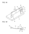
- Fig. 1A is a perspective view showing a structure of the contact switchgear disclosed in Japanese Unexamined Patent Publication No. 6-203726 .
- a base end portion of a movable spring 13 is fixed in a cantilever manner to a moving contact terminal 12 that is vertically provided in an upper surface of a base 11.
- a moving contact 14 is fixed to a leading end portion of the movable spring 13 that extends in parallel with the upper surface of the base 11.
- a fixed contact 16 is fixed opposite the moving contact 14 in an upper end portion of a fixed contact plate 15 that is vertically provided in the upper surface of the base 11.
- An operation controlling member 17 bent into an L-shape is attached to the upper end portion of the fixed contact plate 15, and a leading end 17a of the operation controlling member 17 is opposite the leading end portion of the movable spring 13.
- the movable spring 13 is separated from the leading end 17a of the operation controlling member 17 as shown in Fig. 1B , and the spring modulus of the movable spring 13 is returned to the original spring modulus.
- Japanese Unexamined Patent Publication No. 2000-164104 discloses an electrostatic micro-relay, in which a movable substrate having a spring property is overlapped on a substrate in which a fixed contact and a fixed electrode are provided, and a moving contact that is opposite the fixed contact and a movable electrode that is opposite the fixed electrode are provided in a lower surface of the movable substrate.
- a projection portion is provided in at least one of the movable electrode and the fixed electrode, the projection portion is brought into contact with the other of the movable electrode and the fixed electrode before the moving contact and the fixed contact abut on each other, and the opening force is increased by an elastic deformation partially generated in the movable spring near the projection portion.
- the original spring modulus of the movable spring can arbitrarily be increased by a position or a height of the projection portion, there is a restriction to the position or the height, which results in a problem in that a degree of freedom of design is degraded by processing preciseness or troublesome design.
- the present invention has been devised to solve the problems described above, and an object thereof is to increase an opening force when the movable electrode is separated from the fixed electrode, to simplify the structure, and to enhance the degree of freedom of the design in an electrostatic relay in which the moving contact and the movable electrode are displaced in parallel with the base substrate.
- an electrostatic relay includes: a base substrate; a fixed contact portion that is fixed to the base substrate, the fixed contact portion including a fixed contact; a moving contact portion that includes a moving contact to be brought into contact with or separated from the fixed contact; a fixed electrode portion that is fixed to the base substrate; a movable electrode portion that is displaced along with the moving contact portion toward a direction parallel to the base substrate by an electrostatic force generated between the fixed electrode portion and the movable electrode portion; a first spring member that returns the displaced movable electrode portion to an original position; and a second spring member that abuts on one of a fixed portion fixed to the base substrate and the movable electrode portion or a movable portion displaced along with the movable electrode portion while being not deformed until abutting on one of the fixed portion and the movable electrode portion or the movable portion before the moving contact portion abuts on the fixed contact when the moving contact portion and the movable electrode portion are displaced, the second spring member that abuts on one of
- the fixed portion is a member that is fixed to the base substrate.
- the fixed portion may be the fixed contact portion or the fixed electrode portion or a fixed member (for example, the spring supporting portion) except the fixed contact portion and the fixed electrode portion.
- the movable member may be the moving contact portion or a member except the moving contact portion.
- the member in which the second spring member is provided is the fixed electrode portion or the fixed contact portion while the member on which the second spring member abuts is the movable electrode portion or the moving contact portion
- the member in which the second spring member is provided is the movable electrode portion or the moving contact portion while the member on which the second spring member abuts is the fixed electrode portion or the fixed contact portion
- it is necessary that the second spring member has an insulating property.
- the second spring member that is different from the first spring member is provided in the other of the fixed portion and the movable electrode portion or the movable portion, and the second spring member is not deformed until abutting on one of the fixed member and movable electrode portion or the movable member. Therefore, the structure that elastically returns the movable electrode portion or the movable portion can be simplified to facilitate production of the electrostatic relay. Additionally, because the spring modulus of the second spring member and a moving distance of the movable portion in changing the spring modulus can independently be determined, the degree of freedom of the design is enhanced to facilitate the design of the electrostatic relay.
- the second spring member is a plate spring that is fixed in a cantilever manner to the other of the fixed portion and the movable electrode portion or the movable portion. Accordingly, because the second spring member is formed into the cantilever shape, a displacement amount can be increased compared with the case where the second spring member is provided in a fixed-fixed beam manner, and the cantilever second spring member can deal with the large displacement amount of the movable portion.
- the second spring member is not connected to one of the fixed portion and the movable electrode portion or the movable portion. Accordingly, the second spring member is not deformed until the second spring member abuts on one of the fixed member and the movable electrode portion or the movable member.
- the second spring member abuts on a projection portion that is provided in one of the fixed portion and the movable electrode portion or the movable portion. Accordingly, a point of action of a force applied to the second spring member is changed by changing the position of the projection portion, so that the spring modulus of the second spring member can be changed.
- a plate-shaped second spring member that is provided in a cantilever manner to the other of the fixed portion and the movable electrode portion or the movable portion can abut one a projection portion that is provided in one of the fixed portion and the movable electrode portion or the movable portion, and a length direction of the second spring member that is not deformed is parallel to a surface in which the projection portion is provided. Accordingly, the design is facilitated, because a distance between the projection portion and the second spring member is not changed even if the position of the projection portion is changed along a surface in which the projection portion is provided.
- the second spring member is provided in a spring supporting portion fixed to the base substrate between the movable electrode portion and the fixed contact portion. Accordingly, the spring supporting portion that retains the second spring member can be provided by utilizing spaces on both sides of the moving contact portion.
- second spring members are provided at positions that are symmetrical in relation to a center line of the movable electrode portion. Accordingly, because the second spring members are symmetrically provided, a force applied to the movable portion becomes asymmetric after the fixed portion or the movable portion abuts on the second spring member, and there is no risk of inclining the movable portion.
- the first spring members are provided in both end faces in the direction in which the movable electrode portion is displaced, or the first spring members are provided opposite the end faces, respectively. Accordingly, because the movable electrode portion can float from the base substrate by retaining the movable electrode portion from both sides with the first spring member, the movable electrode portion can be stabilized.
- the first spring member is provided in one of end faces in the direction in which the movable electrode portion is displaced, or the first spring member is provided opposite one of the end faces. Accordingly, because the first spring member is provided only on one side of the movable electrode portion, the structure of the electrostatic relay can be simplified and miniaturized.
- the means for solving the problem in the present invention has the feature that the above constituents are appropriately combined, and many variations can be made by combining the constituents in the present invention.
- Figs 1A is a perspective view of a contact switchgear disclosed in Japanese Unexamined Patent Publication No. 6-203726
- Fig. 1B is a plan view of the contact switchgear when contacts come into contact with each other;
- Fig. 2 is a plan view showing a structure of an electrostatic relay 31 according to a first embodiment of the present invention.
- Fig. 7B is a sectional view taken on a line A-A of Fig. 2 .
- the structure of the electrostatic relay 31 will be described with reference to Figs. 2 and 7B .
- a fixed contact portion 33, a moving contact portion 34, a fixed electrode portion 35, a movable electrode portion 36, movable springs 37a and 37b (first spring member), and spring supporting portions 38 and 39 are provided in an upper surface of a base substrate 32 formed by an Si substrate in the electrostatic relay 31.
- a switch is formed by the fixed contact portion 33 and the moving contact portion 34, and an electrostatic actuator for opening and closing the switch is formed by the fixed electrode portion 35, the movable electrode portion 36, the movable springs 37a and 37b, and the spring supporting portions 38 and 39.
- a lower surface of an Si fixed contact substrate 41 is fixed to an upper surface of the base substrate 32 through a SiO 2 insulating film 42.
- the fixed contact substrate 41 extends long in a width direction (X-direction) in an upper-surface end portion of the base substrate 32.
- An SiN insulating layer 43 is formed in the upper surface of the fixed contact substrate 41, and a pair of wiring pattern portions 44a and 44b is provided on the insulating layer 43.
- the wiring pattern portions 44a and 44b are horizontally divided in the upper surface of the fixed contact substrate 41, and metallic pad portions 45a and 45b are formed in end portions of the wiring pattern portions 44a and 44b.
- a direction in which the moving contact portion 34 and the movable electrode portion 36 move in the electrostatic relay 31 is referred to as a Y-direction, and a width direction of the electrostatic relay 31 is referred to as an X-direction.
- the moving contact portion 34 is provided opposite the fixed contacts 46a and 46b.
- an SiN insulating layer 53 is formed on an upper surface of an Si moving contact substrate 51, and a contact layer 54 is formed on the insulating layer 53.
- An end face of the contact layer 54 that is opposite fixed contacts 46a and 46b is projected from a front face of the moving contact substrate 51 to constitute a moving contact 56.
- the moving contact substrate 51 is supported in a cantilever manner by a support beam 57 that is projected from the movable electrode portion 36.
- the lower surfaces of the moving contact substrate 51 and support beam 57 float from the upper surface of the base substrate 32, and the moving contact substrate 51 and the support beam 57 can move along with the movable electrode portion 36 in a length direction (Y-direction) of the base substrate 32.
- a main circuit (not shown) is connected to the metallic pad portions 45a and 45b of the fixed contact portion 33, and the main circuit can be closed by bringing the moving contact 56 into contact with the fixed contacts 46a and 46b.
- the main circuit can be opened by separating the moving contact 56 from the fixed contacts 46a and 46b.
- An electrostatic actuator that moves the moving contact portion 34 includes the fixed electrode portion 35, the movable electrode portion 36, the movable springs 37a and 37b, and the spring supporting portions 38 and 39.
- plural fixed electrode portions 35 are disposed in parallel with one another in the upper surface of the base substrate 32.
- branch-shaped electrodes 67 extend toward the Y-direction from both surfaces of a rectangular pad portion 66.
- branch portions 68 are projected so as to become horizontally symmetrical, and the branch portions 68 are arrayed in the Y-direction at constant intervals.
- a lower surface of a fixed electrode substrate 61 is fixed to the upper surface of the base substrate 32 by an SiO 2 insulating film 62.
- a conductive layer 63 is formed on the upper surface of the fixed electrode substrate 61 in the pad portion 66, and the pad portion 66 includes an electrode pad layer 64 on the conductive layer 63.
- the movable electrode portion 36 is formed into a frame shape so as to surround each fixed electrode portion 35.
- comb-shaped electrodes 72 are formed so as to sandwich the fixed electrode portions 35 from both sides therebetween (the pair of comb-shaped electrodes 72 is formed into the branch shape between the fixed electrode portions 35).
- the comb-shaped electrode 72 is symmetrical in relation to each fixed electrode portion 35, and comb-shaped portions 73 extend from each comb-shaped electrode 72 toward a gap portion between the branch portions 68.
- a distance from the branch portion 68 that is adjacent to the comb-shaped portion 73 and located closer to the moving contact portion 34 is shorter than a distance from the branch portion 68 that is adjacent to the comb-shaped portion 73 and located farther away from the moving contact portion 34.
- the movable electrode portion 36 is formed by an Si movable electrode substrate 71, and the lower surface of the movable electrode substrate 71 floats from the upper surface of the base substrate 32.
- the support beam 57 is projected in the center of the end face on the moving contact side of the movable electrodes portion 36, and the moving contact substrate 51 is retained at a leading end of the support beam 57.
- the movable electrode portion 36 is retained by the movable spring 37a supported by the spring supporting portion 38 and the movable spring 37b supported by the spring supporting portion 39.
- the two spring supporting portions 38 are symmetrically disposed in a region between the fixed contact portion 33 and the movable electrode portion 36.
- the spring supporting portion 38 made of Si is fixed to the upper surface of the base substrate 32 through an insulating film (not shown).
- coupling portions 81 are projected in the Y-direction from both sides of the support beam 57.
- a leading end of the coupling portion 81 and the spring supporting portion 38 are coupled by the plate-shaped or beam-shaped movable spring 37a made of Si.
- the movable spring 37a is parallel to an X-direction when being not deformed.
- the spring supporting portion 39 made of Si extends in the X-direction in the rear end portion of the base substrate 32.
- the lower surface of the spring supporting portion 39 is fixed to the upper surface of the base substrate 32 by an insulating film 82.
- Coupling portions 83 are projected forward from both ends of the spring supporting portion 39, and the coupling portions 83 and the rear end face of the movable electrode portion 36 are connected by the pair of symmetrically-formed movable springs 37b made of Si.
- the movable spring 37b is formed into the plate shape or beam shape and disposed in parallel with the X-direction.
- the movable electrode portion 36 is retained by the spring supporting portions 38 and 39 with the movable springs 37a and 37b interposed therebetween, and the movable electrode portion 36 is horizontally retained while floating from the upper surface of the base substrate 32.
- the movable electrode portion 36 can be displaced in the Y-direction by elastically deforming the movable springs 37a and 37b, and the movable electrode portion 36 is returned to an original position by elastic restoring forces of the movable springs 37a and 37b when the electrostatic force displacing the movable electrode portion 36 is released.
- each of the pair of movable springs 37a and the pair of movable springs 37b has the symmetrical shape, the movable electrode portion 36 can be displaced in the Y-direction while not being able to be displaced in the X-direction when the movable springs 37a and 37b are deformed to displace the movable electrode portion 36.
- a DC voltage source is connected between the fixed electrode portion 35 and the movable electrode portion 36, and the DC voltage is applied by a control circuit.
- the fixed electrode portion 35 one of terminals of the DC voltage source is connected to the electrode pad layer 64.
- the other terminal of the DC voltage source is connected to the spring supporting portion 39.
- the spring supporting portion 39 and the movable spring 37b have conductivity, and the spring supporting portion 39, the movable spring 37b, and the movable electrode portion 36 are electrically connected. Therefore, the voltage applied to the spring supporting portion 39 is applied to the movable electrode portion 36.
- each come-shaped portion 73 is attracted to the moving contact portion side, and the movable electrode portion 36 moves in the Y-direction while the movable springs 37a and 37b are bent.
- the moving contact portion 34 moves onto the side of the fixed contact portion 33, and the moving contact 56 comes into contact with the fixed contacts 46a and 46b to electrically close (the main circuit) between the fixed contact 46a and the fixed contact 46b.
- the electrostatic actuator is driven by utilizing the electrostatic force, there is a risk that the moving contact 56 is not separated from the fixed contacts 46a and 46b even if the DC voltage applied between the fixed electrode portion 35 and the movable electrode portion 36 is released. This is because the electrodes 35 and 36 remain attracted to each other by the induction polarization or the electrostatic induction or the contacts are not separated by the adhesive force generated between the contacts even if the DC voltage applied between the fixed electrode portion 35 and the movable electrode portion 36 is released. Accordingly, in order to separate the fixed contacts 46a and 46b from the moving contact 56, the movable springs 37a and 37b having the large spring moduli are required to separate the fixed contacts 46a and 46b from the moving contact 56. However, when the spring moduli of the movable springs 37a and 37b are increased, the electrostatic actuator having the stronger electrostatic force is required to displace the movable electrode portion 36.
- secondary springs 84 (second spring member) are provided in the spring supporting portions 38, and the elastic restoring forces of the secondary springs 84 are applied when the fixed contacts 46a and 46b and the moving contact 56 are separated from each other.
- the plate-shaped or beam-shaped secondary springs 84 made of Si are provided in the spring supporting portions 38 at positions at which the secondary springs 84 are opposite the front end face of the movable electrode portion 36.
- the spring supporting portion 38 is a fixed portion that is fixed to the upper surface of the base substrate 32, and the secondary spring 84 is not joined to the movable portions such as the movable electrode portion 36.
- the secondary spring 84 When being not deformed, the secondary spring 84 extends in parallel with the front end face of the movable electrode portion 36. On the other hand, projection portions 85 are projected opposite the leading end portions of the secondary springs 84 from the front end face of the movable electrode portion 36.
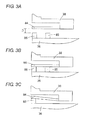
- a length of the projection portion 85 or a distance between the leading end of the projection portion 85 and the secondary spring 84 is determined such that an operation shown in Fig. 3 is performed.
- the movable electrode portion 36 is not displaced, there is a distance D between the secondary spring 84 and the leading end of the projection portion 85 as shown in Fig. 3A .
- the movable electrode portion 36 moves a distance larger than the distance D while bending the movable springs 37a and 37b.
- the leading end of the projection portion 85 abuts on the secondary spring 84 as shown in Fig. 3B . At this point, the moving contact 56 does not yet come into contact with the fixed contacts 46a and 46b.
- the projection portion 85 comes into contact with the secondary spring 84 before the moving contact 56 comes into contact with the fixed contacts 46a and 46b.
- the movable electrode portion 36 moves beyond the distance D, as shown in Fig. 3C , the movable electrode portion 36 moves while bending the movable springs 37a and 37b and the secondary spring 84, and the movable electrode portion 36 stops while bringing the moving contact 56 into contact with the fixed contacts 46a and 46b.
- the movable electrode portion 36 is pushed back by the elastic restoring forces of the movable springs 37a and 37b and secondary spring 84, and the movable electrode portion 36 is separated from the fixed electrode portion 35 by the strong force and returned to the original position.
- the pair of movable springs 37a, the pair of movable springs 37b, the pair of secondary springs 84, and the pair of projection portions 85 are symmetrically formed in relation to the center axis parallel to the Y-direction of the movable electrode portion 36 such that the movable electrode portion 36 moves in the Y-direction without inclining the movable electrode portion 36.
- the pair of movable springs 37a, the pair of movable springs 37b, and the pair of secondary springs 84 has the identical spring modulus.
- the secondary springs 84 that are different from the movable springs 37a and 37b are provided to increase the spring force for returning the movable electrode portion 36, and the secondary springs 84 are not deformed until abutting on the projection portion 85. Therefore, the degree of freedom of the design is enhanced between the secondary spring 84 and the projection portion 85 to facilitate the design.
- the spring modulus of the secondary spring 84 can be increased by moving the position of the projection portion 85 onto the base end side of the secondary spring 84.
- the spring modulus of the secondary spring 84 can be decreased by moving the projection portion 85 onto the leading end side of the secondary spring 84 (because the point of action of the force is changed when the position of the projection portion 85 is changed, moment applied to the secondary spring 84 is changed). Additionally, irrespective of the position of the projection portion 85 even if the position of the projection portion 85 is changed, the projection portion 85 abuts on the secondary spring 84 when the movable electrode portion 36 moves the distance D as shown in Fig. 3B .
- the spring modulus of the secondary spring 84 can be adjusted by the position of the projection portion 85, the moving distance D in which the projection portion 85 abuts on the secondary spring 84 can be adjusted by the length of the projection portion 85, and the spring modulus and the distance D can independently be adjusted, so that the degree of freedom of the design is enhanced.
- the movable electrode portion 36 is pushed back by the elastic restoring forces of the movable spring 37b and movable spring 37a whose spring modulus is increased, and the movable electrode portion 36 is separated from the fixed electrode portion 35 by the strong force.
- the movable spring 37a is bent with the movement of the movable electrode portion 36, and the bent movable spring 37a abuts on the leading end of the projection 86 as shown in Fig. 5B . Therefore, exactly it cannot be said that the movable spring 37a abuts on the projection 86 when the movable electrode portion 36 moves the distance D. That is, because the moving distance of the movable electrode portion 36 depends on the bending shape of the movable spring 37a, the moving distance is larger than the distance D when the movable spring 37a abuts on the projection 86.
- the spring modulus of the movable spring 37a can be changed by moving the position of the projection 86.
- the moving distance of the movable electrode portion 36 is changed only by simply moving the projection 86 when the movable spring 37a abuts on the projection 86. Therefore, in order that the moving distance is not changed when the movable spring 37a abuts on the projection 86, it is necessary to adjust the length (projection length) of the projection 86 according to the position of the projection 86 as shown by an alternate long and two short dashes line in Fig. 5B .
- the spring modulus of the movable spring 37a and the length of the projection 86 cannot independently be determined, and the design becomes complicated.
- the spring modulus of the secondary spring 84 and the moving distance of the movable electrode portion 36 in changing the spring modulus can independently be determined to facilitate the design.
- a substrate shown in Fig. 6A is an SOl substrate 94 in which an Si substrate 91 and an Si substrate 93 are joined while an oxide film (SiO 2 ) 92 is sandwiched between the Si substrate 91 and the Si substrate 93.
- the conductive layer 63 and electrode pad layer 64 of the pad portion 66 are formed on the SOl substrate 94, an SiN insulating layer 95 is formed on the SOl substrate 94, and the wiring pattern portions 44a and 44b of the fixed contact portion 33 and the contact layer 54 of the moving contact portion 34 are formed on the SiN insulating layer 95.
- the Si substrate 91 that is of the lower-most layer constitutes the base substrate 32.
- a photoresist film 96 is deposited on the surface of the Si substrate 93, the photoresist film 96 is patterned such that regions constituting the fixed contact portion 33, the moving contact portion 34, the fixed electrode portion 35, the movable electrode portion 36, the movable springs 37a and 37b, the spring supporting portions 38 and 39, the secondary spring 84, and the projection portion 85 are coated with the photoresist film 96.
- the exposed region of the Si substrate 93 is dry-etched with the photoresist film 96 as an etching mask, and the fixed contact substrate 41 of the fixed contact portion 33, the moving contact substrate 51 of the moving contact portion 34, the fixed electrode substrate 61 of the fixed electrode portion 35, the movable electrode substrate 71 of the movable electrode portion 36, the movable springs 37a and 37b, the spring supporting portions 38 and 39, the secondary spring 84, and the projection portion 85 (electrostatic actuator and a switch substrate portion) are formed as shown in Fig. 6C .
- the exposed portion of the insulating layer 95 is etched to form the insulating layer 43 of the fixed contact portion 33 and the insulating layer 53 of the moving contact portion 34.
- the exposed portion of the oxide film 92 and the oxide films 92 located in the lower surfaces of the moving contact portion 34 and movable portion (the movable electrode portion 36, the movable springs 37a and 37b, and the secondary spring 84) of the electrostatic actuator are removed by wet etching to prepare the electrostatic relay 31 as shown in Fig. 7B .
- Fig. 8 is a plan view showing an electrostatic relay 101 according to a modification of the first embodiment.
- coupling portions 102 are projected from both ends in the front end face of the movable electrodes portion 36, the secondary springs 84 are provided in the cantilever manner in the leading end portions of the coupling portions 102, and the secondary springs 84 are disposed in parallel with the surfaces of the spring supporting portions 38 that are opposite the secondary springs 84.
- the projection portion 85 is provided in the surface that is opposite the secondary spring 84 of the spring supporting portion 38 such that the secondary spring 84 abuts on the projection portion 85.
- Fig. 9 is a plan view showing a structure of an electrostatic relay 111 according to a second embodiment of the present invention.
- a movable spring 37a is provided in a fixed-fixed beam manner in the spring supporting portion 38, and the coupling portion 81 that is projected from the front end portion of the movable electrode portion 36 is coupled to the central portion of the movable spring 37a.
- the movable spring 37a constitutes the fixed-fixed beam, so that the spring modulus of the movable spring 37a can be increased.
- the movable springs 37a and 37b that support the movable electrode portion 36 are provided in the front end face and rear end face of the movable electrode portion 36.
- the movable springs 37a and 37b may be provided in the front end face or rear end face of the movable electrode portion 36.
- the projection portion 85 may be provided in the secondary spring 84 instead of providing the projection portion 85 in the surface that is opposite the secondary spring 84.
- the positions at which the secondary spring 84 and the projection portion 85 are provided are not limited to the region between the front end face of the movable electrode portion 36 and the spring supporting portion 38, but the secondary spring 84 and the projection portion 85 may be provided at any position.
Landscapes
- Physics & Mathematics (AREA)
- Electromagnetism (AREA)
- Micromachines (AREA)
Abstract
Description
- The present invention relates to a compact electrostatic relay (electrostatic micro-relay), specifically to a structure of a secondary spring that elastically restores a movable portion in an electrostatic relay.
- In the electrostatic relay, when a moving contact is brought into contact with a fixed contact, an electrostatic actuator is driven to displace the moving contact. When the moving contact and the fixed contact are separated from each other, the moving contact is separated from the fixed contact by an elastic restoring force of a movable spring that is elastically deformed in driving the electrostatic actuator.
- In driving the electrostatic actuator, a DC voltage is applied between a movable electrode and a fixed electrode, and the movable electrode is attracted to the fixed electrode by an electrostatic force that acts between the electrodes, thereby displacing a member in which the movable electrode is provided. However, in the electrostatic actuator, due to electrostatic induction or induction polarization generated between the electrodes, occasionally the movable electrode is attracted to and not separated from fixed electrode even if the DC voltage applied between the movable electrode and the fixed electrode is turned off. Further, occasionally the moving contact and the fixed contact are not separated by an adhesive force that is generated when the fixed contact and the moving contact come into contact with each other. Therefore, when the movable electrode is attracted to the fixed electrode, or when the moving contact is in contact with the fixed contact, it is necessary to increase a spring modulus of the movable spring.
- For example, Japanese Unexamined Patent Publication No.
6-203726 Fig. 1A is a perspective view showing a structure of the contact switchgear disclosed in Japanese Unexamined Patent Publication No.6-203726 Fig. 1A , a base end portion of amovable spring 13 is fixed in a cantilever manner to a movingcontact terminal 12 that is vertically provided in an upper surface of abase 11. A movingcontact 14 is fixed to a leading end portion of themovable spring 13 that extends in parallel with the upper surface of thebase 11. A fixedcontact 16 is fixed opposite the movingcontact 14 in an upper end portion of afixed contact plate 15 that is vertically provided in the upper surface of thebase 11. Anoperation controlling member 17 bent into an L-shape is attached to the upper end portion of the fixedcontact plate 15, and a leadingend 17a of theoperation controlling member 17 is opposite the leading end portion of themovable spring 13. - When a rear surface of the
movable spring 13 is pressed by adriving member 18, themovable spring 13 is elastically curved, and the leading end portion of themovable spring 13 abuts on the leadingend 17a of theoperation controlling member 17. When themovable spring 13 is further pressed by thedriving member 18, the movingcontact 14 is pressed on the fixedcontact 16 to close between the movingcontact 14 and the fixedcontact 16. In the contact switchgear disclosed in Japanese Unexamined Patent Publication No.6-203726 movable spring 13 abuts on theoperation controlling member 17 before the moving contact and the fixed contact come into contact with each other, thereby achieving shock relaxation of the contact and reduced contact bounce time. - In the contact switchgear disposed in Japanese Unexamined Patent Publication No.
6-203726 contact 14 is brought into contact with the fixedcontact 16, themovable spring 13 abuts on the leadingend 17a of theoperation controlling member 17 to increase the spring modulus of themovable spring 13. However, in the contact switchgear disclosed in Japanese Unexamined Patent Publication No.6-203726 member 18 is the electromagnetic force, the spring modulus of themovable spring 13 is not increased in order to separate the movable electrode and fixed electrode of the electrostatic actuator. Additionally, in the contact switchgear, while the movingcontact 14 is in contact with the fixedcontact 16, themovable spring 13 is separated from the leadingend 17a of theoperation controlling member 17 as shown inFig. 1B , and the spring modulus of themovable spring 13 is returned to the original spring modulus. - Japanese Unexamined Patent Publication No.
2000-164104 - In the electrostatic relay, although the original spring modulus of the movable spring can arbitrarily be increased by a position or a height of the projection portion, there is a restriction to the position or the height, which results in a problem in that a degree of freedom of design is degraded by processing preciseness or troublesome design.
- The present invention has been devised to solve the problems described above, and an object thereof is to increase an opening force when the movable electrode is separated from the fixed electrode, to simplify the structure, and to enhance the degree of freedom of the design in an electrostatic relay in which the moving contact and the movable electrode are displaced in parallel with the base substrate.
- In accordance with an aspect of the present invention, an electrostatic relay includes: a base substrate; a fixed contact portion that is fixed to the base substrate, the fixed contact portion including a fixed contact; a moving contact portion that includes a moving contact to be brought into contact with or separated from the fixed contact; a fixed electrode portion that is fixed to the base substrate; a movable electrode portion that is displaced along with the moving contact portion toward a direction parallel to the base substrate by an electrostatic force generated between the fixed electrode portion and the movable electrode portion; a first spring member that returns the displaced movable electrode portion to an original position; and a second spring member that abuts on one of a fixed portion fixed to the base substrate and the movable electrode portion or a movable portion displaced along with the movable electrode portion while being not deformed until abutting on one of the fixed portion and the movable electrode portion or the movable portion before the moving contact portion abuts on the fixed contact when the moving contact portion and the movable electrode portion are displaced, the second spring member being provided in the other of the fixed portion and the movable portion. The fixed portion is a member that is fixed to the base substrate. The fixed portion may be the fixed contact portion or the fixed electrode portion or a fixed member (for example, the spring supporting portion) except the fixed contact portion and the fixed electrode portion. The movable member may be the moving contact portion or a member except the moving contact portion. However, when the member in which the second spring member is provided is the fixed electrode portion or the fixed contact portion while the member on which the second spring member abuts is the movable electrode portion or the moving contact portion, or when the member in which the second spring member is provided is the movable electrode portion or the moving contact portion while the member on which the second spring member abuts is the fixed electrode portion or the fixed contact portion, it is necessary that the second spring member has an insulating property.
- In the electrostatic relay according to the aspect of the present invention, the second spring member that is different from the first spring member is provided in the other of the fixed portion and the movable electrode portion or the movable portion, and the second spring member is not deformed until abutting on one of the fixed member and movable electrode portion or the movable member. Therefore, the structure that elastically returns the movable electrode portion or the movable portion can be simplified to facilitate production of the electrostatic relay. Additionally, because the spring modulus of the second spring member and a moving distance of the movable portion in changing the spring modulus can independently be determined, the degree of freedom of the design is enhanced to facilitate the design of the electrostatic relay.
- In the electrostatic relay according to the aspect of the present invention, preferably the second spring member is a plate spring that is fixed in a cantilever manner to the other of the fixed portion and the movable electrode portion or the movable portion. Accordingly, because the second spring member is formed into the cantilever shape, a displacement amount can be increased compared with the case where the second spring member is provided in a fixed-fixed beam manner, and the cantilever second spring member can deal with the large displacement amount of the movable portion.
- In the electrostatic relay according to the aspect of the present invention, preferably the second spring member is not connected to one of the fixed portion and the movable electrode portion or the movable portion. Accordingly, the second spring member is not deformed until the second spring member abuts on one of the fixed member and the movable electrode portion or the movable member.
- In the electrostatic relay according to the aspect of the present invention, preferably the second spring member abuts on a projection portion that is provided in one of the fixed portion and the movable electrode portion or the movable portion. Accordingly, a point of action of a force applied to the second spring member is changed by changing the position of the projection portion, so that the spring modulus of the second spring member can be changed.
- In the electrostatic relay according to the aspect of the present invention, preferably a plate-shaped second spring member that is provided in a cantilever manner to the other of the fixed portion and the movable electrode portion or the movable portion can abut one a projection portion that is provided in one of the fixed portion and the movable electrode portion or the movable portion, and a length direction of the second spring member that is not deformed is parallel to a surface in which the projection portion is provided. Accordingly, the design is facilitated, because a distance between the projection portion and the second spring member is not changed even if the position of the projection portion is changed along a surface in which the projection portion is provided.
- In the electrostatic relay according to the aspect of the present invention, preferably the second spring member is provided in a spring supporting portion fixed to the base substrate between the movable electrode portion and the fixed contact portion. Accordingly, the spring supporting portion that retains the second spring member can be provided by utilizing spaces on both sides of the moving contact portion.
- In the electrostatic relay according to the aspect of the present invention, preferably second spring members are provided at positions that are symmetrical in relation to a center line of the movable electrode portion. Accordingly, because the second spring members are symmetrically provided, a force applied to the movable portion becomes asymmetric after the fixed portion or the movable portion abuts on the second spring member, and there is no risk of inclining the movable portion.
- In the electrostatic relay according to the aspect of the present invention, preferably the first spring members are provided in both end faces in the direction in which the movable electrode portion is displaced, or the first spring members are provided opposite the end faces, respectively. Accordingly, because the movable electrode portion can float from the base substrate by retaining the movable electrode portion from both sides with the first spring member, the movable electrode portion can be stabilized.
- In the electrostatic relay according to the aspect of the present invention, preferably the first spring member is provided in one of end faces in the direction in which the movable electrode portion is displaced, or the first spring member is provided opposite one of the end faces. Accordingly, because the first spring member is provided only on one side of the movable electrode portion, the structure of the electrostatic relay can be simplified and miniaturized.
- The means for solving the problem in the present invention has the feature that the above constituents are appropriately combined, and many variations can be made by combining the constituents in the present invention.
-
Figs 1A is a perspective view of a contact switchgear disclosed in Japanese Unexamined Patent Publication No.6-203726 Fig. 1B is a plan view of the contact switchgear when contacts come into contact with each other; -
Fig. 2 is a plan view showing an electrostatic relay according to a first embodiment of the present invention; -
Figs. 3A to 3C are schematic diagrams explaining an operation between a secondary spring and a projection portion in the electrostatic relay of the first embodiment; -
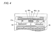
Fig. 4 is a partially cutaway plan view showing an electrostatic relay of a comparative example; -
Figs. 5A to 5C are schematic diagrams explaining an operation between a movable spring and a projection portion in the electrostatic relay of a comparative example; -
Figs. 6A to 6C are sectional views showing a process of producing the electrostatic relay of the first embodiment; -
Figs. 7A and 7B are sectional views showing the process of producing the electrostatic relay of the first embodiment and show a process subsequent toFig. 6C ; -
Fig. 8 is a plan view showing an electrostatic relay according to a modification of the first embodiment; and -
Fig. 9 is a plan view showing an electrostatic relay according to a second embodiment of the present invention. - Hereinafter, preferred embodiments of the present invention will be described with reference to the drawings. However, the present invention is not limited to the following embodiments, but various design changes can be made without departing from the scope of the present invention.
-
Fig. 2 is a plan view showing a structure of anelectrostatic relay 31 according to a first embodiment of the present invention.Fig. 7B is a sectional view taken on a line A-A ofFig. 2 . The structure of theelectrostatic relay 31 will be described with reference toFigs. 2 and7B . - A fixed
contact portion 33, a movingcontact portion 34, a fixedelectrode portion 35, amovable electrode portion 36,movable springs spring supporting portions base substrate 32 formed by an Si substrate in theelectrostatic relay 31. In theelectrostatic relay 31, a switch is formed by the fixedcontact portion 33 and the movingcontact portion 34, and an electrostatic actuator for opening and closing the switch is formed by the fixedelectrode portion 35, themovable electrode portion 36, themovable springs spring supporting portions - As shown in
Figs. 2 and7B , in the fixedcontact portion 33, a lower surface of an Si fixedcontact substrate 41 is fixed to an upper surface of thebase substrate 32 through a SiO2 insulating film 42. The fixedcontact substrate 41 extends long in a width direction (X-direction) in an upper-surface end portion of thebase substrate 32. AnSiN insulating layer 43 is formed in the upper surface of the fixedcontact substrate 41, and a pair ofwiring pattern portions layer 43. Thewiring pattern portions contact substrate 41, andmetallic pad portions wiring pattern portions wiring pattern portions contact substrate 41, extend in parallel with each other, and the end portions located opposite the movingcontact portion 34 constitute fixedcontacts contact portion 34 and themovable electrode portion 36 move in theelectrostatic relay 31 is referred to as a Y-direction, and a width direction of theelectrostatic relay 31 is referred to as an X-direction. - The moving
contact portion 34 is provided opposite the fixedcontacts contact portion 34, anSiN insulating layer 53 is formed on an upper surface of an Si movingcontact substrate 51, and acontact layer 54 is formed on the insulatinglayer 53. An end face of thecontact layer 54 that is opposite fixedcontacts contact substrate 51 to constitute a movingcontact 56. - The moving
contact substrate 51 is supported in a cantilever manner by asupport beam 57 that is projected from themovable electrode portion 36. The lower surfaces of the movingcontact substrate 51 andsupport beam 57 float from the upper surface of thebase substrate 32, and the movingcontact substrate 51 and thesupport beam 57 can move along with themovable electrode portion 36 in a length direction (Y-direction) of thebase substrate 32. - In the
electrostatic relay 31, a main circuit (not shown) is connected to themetallic pad portions contact portion 33, and the main circuit can be closed by bringing the movingcontact 56 into contact with the fixedcontacts contact 56 from the fixedcontacts - An electrostatic actuator that moves the moving
contact portion 34 includes the fixedelectrode portion 35, themovable electrode portion 36, themovable springs spring supporting portions - As shown in
Fig. 2 , plural fixedelectrode portions 35 are disposed in parallel with one another in the upper surface of thebase substrate 32. When the fixedelectrode portion 35 is viewed from above, branch-shapedelectrodes 67 extend toward the Y-direction from both surfaces of arectangular pad portion 66. In the branch-shapedelectrode 67,branch portions 68 are projected so as to become horizontally symmetrical, and thebranch portions 68 are arrayed in the Y-direction at constant intervals. - As shown in
Fig. 7B , in the fixedelectrode portion 35, a lower surface of a fixedelectrode substrate 61 is fixed to the upper surface of thebase substrate 32 by an SiO2 insulating film 62. Aconductive layer 63 is formed on the upper surface of the fixedelectrode substrate 61 in thepad portion 66, and thepad portion 66 includes anelectrode pad layer 64 on theconductive layer 63. - As shown in
Fig. 2 , themovable electrode portion 36 is formed into a frame shape so as to surround each fixedelectrode portion 35. In themovable electrode portion 36, comb-shapedelectrodes 72 are formed so as to sandwich the fixedelectrode portions 35 from both sides therebetween (the pair of comb-shapedelectrodes 72 is formed into the branch shape between the fixed electrode portions 35). The comb-shapedelectrode 72 is symmetrical in relation to each fixedelectrode portion 35, and comb-shapedportions 73 extend from each comb-shapedelectrode 72 toward a gap portion between thebranch portions 68. In each comb-shapedportion 73, a distance from thebranch portion 68 that is adjacent to the comb-shapedportion 73 and located closer to the movingcontact portion 34 is shorter than a distance from thebranch portion 68 that is adjacent to the comb-shapedportion 73 and located farther away from the movingcontact portion 34. - The
movable electrode portion 36 is formed by an Simovable electrode substrate 71, and the lower surface of themovable electrode substrate 71 floats from the upper surface of thebase substrate 32. Thesupport beam 57 is projected in the center of the end face on the moving contact side of themovable electrodes portion 36, and the movingcontact substrate 51 is retained at a leading end of thesupport beam 57. - The
movable electrode portion 36 is retained by themovable spring 37a supported by thespring supporting portion 38 and themovable spring 37b supported by thespring supporting portion 39. As shown inFig. 2 , the twospring supporting portions 38 are symmetrically disposed in a region between thefixed contact portion 33 and themovable electrode portion 36. Thespring supporting portion 38 made of Si is fixed to the upper surface of thebase substrate 32 through an insulating film (not shown). In a front end face of themovable electrode portion 36,coupling portions 81 are projected in the Y-direction from both sides of thesupport beam 57. A leading end of thecoupling portion 81 and thespring supporting portion 38 are coupled by the plate-shaped or beam-shapedmovable spring 37a made of Si. Themovable spring 37a is parallel to an X-direction when being not deformed. - The
spring supporting portion 39 made of Si extends in the X-direction in the rear end portion of thebase substrate 32. The lower surface of thespring supporting portion 39 is fixed to the upper surface of thebase substrate 32 by an insulatingfilm 82. Couplingportions 83 are projected forward from both ends of thespring supporting portion 39, and thecoupling portions 83 and the rear end face of themovable electrode portion 36 are connected by the pair of symmetrically-formedmovable springs 37b made of Si. Themovable spring 37b is formed into the plate shape or beam shape and disposed in parallel with the X-direction. - Accordingly, the
movable electrode portion 36 is retained by thespring supporting portions movable springs movable electrode portion 36 is horizontally retained while floating from the upper surface of thebase substrate 32. Themovable electrode portion 36 can be displaced in the Y-direction by elastically deforming themovable springs movable electrode portion 36 is returned to an original position by elastic restoring forces of themovable springs movable electrode portion 36 is released. Because each of the pair ofmovable springs 37a and the pair ofmovable springs 37b has the symmetrical shape, themovable electrode portion 36 can be displaced in the Y-direction while not being able to be displaced in the X-direction when themovable springs movable electrode portion 36. - In the
electrostatic relay 31 having the above-described structure, a DC voltage source is connected between the fixedelectrode portion 35 and themovable electrode portion 36, and the DC voltage is applied by a control circuit. In the fixedelectrode portion 35, one of terminals of the DC voltage source is connected to theelectrode pad layer 64. The other terminal of the DC voltage source is connected to thespring supporting portion 39. Thespring supporting portion 39 and themovable spring 37b have conductivity, and thespring supporting portion 39, themovable spring 37b, and themovable electrode portion 36 are electrically connected. Therefore, the voltage applied to thespring supporting portion 39 is applied to themovable electrode portion 36. - When the DC voltage is applied between the fixed
electrode portion 35 and themovable electrode portion 36 by the DC voltage source, an electrostatic attractive force is generated between thebranch portion 68 of the branch-shapedelectrode 67 and the comb-shapedportion 73 of the comb-shapedelectrode 72. However, because the structures of the fixedelectrode portion 35 andmovable electrode portion 36 are symmetrically formed in relation to a center line of each fixedelectrode portion 35, the electrostatic attractive forces acting on themovable electrode portion 36 in the X-direction are balanced, and the movable electrode,portion 36 does not move in the X-direction. On the other hand, because the distance from thebranch portion 68 that is adjacent to each comb-shapedportion 73 and located closer to the movingcontact portion 34 is shorter than the distance from thebranch portion 68 that is adjacent to the comb-shapedportion 73 and located farther away from the movingcontact portion 34, each come-shapedportion 73 is attracted to the moving contact portion side, and themovable electrode portion 36 moves in the Y-direction while themovable springs contact portion 34 moves onto the side of the fixedcontact portion 33, and the movingcontact 56 comes into contact with the fixedcontacts fixed contact 46a and the fixedcontact 46b. - When the DC voltage applied between the fixed
electrode portion 35 and themovable electrode portion 36 is released, the electrostatic attractive force disappears between thebranch portion 68 and the comb-shapedportion 73. Therefore, themovable electrode portion 36 is retreated in the Y-direction by the elastic restoring forces of themovable springs contact 56 is separated from the fixedcontacts fixed contact 46a and the fixedcontact 46b. - In the
electrostatic relay 31, because the electrostatic actuator is driven by utilizing the electrostatic force, there is a risk that the movingcontact 56 is not separated from the fixedcontacts electrode portion 35 and themovable electrode portion 36 is released. This is because theelectrodes electrode portion 35 and themovable electrode portion 36 is released. Accordingly, in order to separate the fixedcontacts contact 56, themovable springs contacts contact 56. However, when the spring moduli of themovable springs movable electrode portion 36. - Therefore, in the
electrostatic relay 31, besides themovable spring spring supporting portions 38, and the elastic restoring forces of thesecondary springs 84 are applied when the fixedcontacts contact 56 are separated from each other. As shown inFig. 2 , the plate-shaped or beam-shapedsecondary springs 84 made of Si are provided in thespring supporting portions 38 at positions at which thesecondary springs 84 are opposite the front end face of themovable electrode portion 36. Thespring supporting portion 38 is a fixed portion that is fixed to the upper surface of thebase substrate 32, and thesecondary spring 84 is not joined to the movable portions such as themovable electrode portion 36. When being not deformed, thesecondary spring 84 extends in parallel with the front end face of themovable electrode portion 36. On the other hand,projection portions 85 are projected opposite the leading end portions of thesecondary springs 84 from the front end face of themovable electrode portion 36. - A length of the
projection portion 85 or a distance between the leading end of theprojection portion 85 and thesecondary spring 84 is determined such that an operation shown inFig. 3 is performed. When themovable electrode portion 36 is not displaced, there is a distance D between thesecondary spring 84 and the leading end of theprojection portion 85 as shown inFig. 3A . In driving the electrostatic actuator, themovable electrode portion 36 moves a distance larger than the distance D while bending themovable springs movable electrode portion 36 moves the distance D, the leading end of theprojection portion 85 abuts on thesecondary spring 84 as shown inFig. 3B . At this point, the movingcontact 56 does not yet come into contact with the fixedcontacts projection portion 85 comes into contact with thesecondary spring 84 before the movingcontact 56 comes into contact with the fixedcontacts movable electrode portion 36 moves beyond the distance D, as shown inFig. 3C , themovable electrode portion 36 moves while bending themovable springs secondary spring 84, and themovable electrode portion 36 stops while bringing the movingcontact 56 into contact with the fixedcontacts - Accordingly, when the DC voltage applied to the electrostatic actuator is released, the
movable electrode portion 36 is pushed back by the elastic restoring forces of themovable springs secondary spring 84, and themovable electrode portion 36 is separated from the fixedelectrode portion 35 by the strong force and returned to the original position. - The pair of
movable springs 37a, the pair ofmovable springs 37b, the pair ofsecondary springs 84, and the pair ofprojection portions 85 are symmetrically formed in relation to the center axis parallel to the Y-direction of themovable electrode portion 36 such that themovable electrode portion 36 moves in the Y-direction without inclining themovable electrode portion 36. The pair ofmovable springs 37a, the pair ofmovable springs 37b, and the pair ofsecondary springs 84 has the identical spring modulus. - In the configuration of the
electrostatic relay 31, thesecondary springs 84 that are different from themovable springs movable electrode portion 36, and thesecondary springs 84 are not deformed until abutting on theprojection portion 85. Therefore, the degree of freedom of the design is enhanced between thesecondary spring 84 and theprojection portion 85 to facilitate the design. In the structure shown inFig. 3A , as shown by an alternate long and two short dashes line inFig. 3A , the spring modulus of thesecondary spring 84 can be increased by moving the position of theprojection portion 85 onto the base end side of thesecondary spring 84. On the other hand, the spring modulus of thesecondary spring 84 can be decreased by moving theprojection portion 85 onto the leading end side of the secondary spring 84 (because the point of action of the force is changed when the position of theprojection portion 85 is changed, moment applied to thesecondary spring 84 is changed). Additionally, irrespective of the position of theprojection portion 85 even if the position of theprojection portion 85 is changed, theprojection portion 85 abuts on thesecondary spring 84 when themovable electrode portion 36 moves the distance D as shown inFig. 3B . Therefore, the spring modulus of thesecondary spring 84 can be adjusted by the position of theprojection portion 85, the moving distance D in which theprojection portion 85 abuts on thesecondary spring 84 can be adjusted by the length of theprojection portion 85, and the spring modulus and the distance D can independently be adjusted, so that the degree of freedom of the design is enhanced. - On the other hand, the degree of freedom of the design is degraded, when the movable spring abuts on the operation controlling member after the movable spring is deformed like Japanese Unexamined Patent Publication No.
6-203726 2000-164104 Fig. 4 . In the comparative example ofFig. 4 , a projection 86 (operation controlling member) is provided opposite themovable spring 37a such that themovable electrode portion 36 abuts on theprojection 86 when moving. - In the comparative example, as shown in
Fig. 5A , there is also the distance D between themovable spring 37a and the leading end of theprojection 86 when themovable electrode portion 36 is not displaced. When themovable electrode portion 36 moves, themovable spring 37a abuts on theprojection 86 as shown inFig. 5B . When themovable spring 37a abuts on theprojection 86 to further move themovable electrode portion 36, because themovable spring 37a is deformed with the leading end of theprojection 86 as a supporting point as shown inFig. 5C , themovable spring 37a is deformed with the increased spring modulus. Accordingly, when the DC voltage applied to the electrostatic actuator is released, themovable electrode portion 36 is pushed back by the elastic restoring forces of themovable spring 37b andmovable spring 37a whose spring modulus is increased, and themovable electrode portion 36 is separated from the fixedelectrode portion 35 by the strong force. - However, in the comparative example, the
movable spring 37a is bent with the movement of themovable electrode portion 36, and the bentmovable spring 37a abuts on the leading end of theprojection 86 as shown inFig. 5B . Therefore, exactly it cannot be said that themovable spring 37a abuts on theprojection 86 when themovable electrode portion 36 moves the distance D. That is, because the moving distance of themovable electrode portion 36 depends on the bending shape of themovable spring 37a, the moving distance is larger than the distance D when themovable spring 37a abuts on theprojection 86. - Even in the comparative example, as shown by an alternate long and two short dashes line in
Fig. 5A , the spring modulus of themovable spring 37a can be changed by moving the position of theprojection 86. However, the moving distance of themovable electrode portion 36 is changed only by simply moving theprojection 86 when themovable spring 37a abuts on theprojection 86. Therefore, in order that the moving distance is not changed when themovable spring 37a abuts on theprojection 86, it is necessary to adjust the length (projection length) of theprojection 86 according to the position of theprojection 86 as shown by an alternate long and two short dashes line inFig. 5B . - In the comparative example, because the position and length of the
projection 86 are correlated with each other, the spring modulus of themovable spring 37a and the length of the projection 86 (or the moving distance of themovable electrode portion 36 when the spring modulus is changed) cannot independently be determined, and the design becomes complicated. On the other hand, in the first embodiment, the spring modulus of thesecondary spring 84 and the moving distance of themovable electrode portion 36 in changing the spring modulus can independently be determined to facilitate the design. - A method for producing the
electrostatic relay 31 will briefly be described below. A substrate shown inFig. 6A is anSOl substrate 94 in which anSi substrate 91 and anSi substrate 93 are joined while an oxide film (SiO2) 92 is sandwiched between theSi substrate 91 and theSi substrate 93. Theconductive layer 63 andelectrode pad layer 64 of thepad portion 66 are formed on theSOl substrate 94, anSiN insulating layer 95 is formed on theSOl substrate 94, and thewiring pattern portions contact portion 33 and thecontact layer 54 of the movingcontact portion 34 are formed on theSiN insulating layer 95. TheSi substrate 91 that is of the lower-most layer constitutes thebase substrate 32. - Then, as shown in
Fig. 6B , a photoresist film 96 is deposited on the surface of theSi substrate 93, the photoresist film 96 is patterned such that regions constituting the fixedcontact portion 33, the movingcontact portion 34, the fixedelectrode portion 35, themovable electrode portion 36, themovable springs spring supporting portions secondary spring 84, and theprojection portion 85 are coated with the photoresist film 96. - The exposed region of the
Si substrate 93 is dry-etched with the photoresist film 96 as an etching mask, and the fixedcontact substrate 41 of the fixedcontact portion 33, the movingcontact substrate 51 of the movingcontact portion 34, the fixedelectrode substrate 61 of the fixedelectrode portion 35, themovable electrode substrate 71 of themovable electrode portion 36, themovable springs spring supporting portions secondary spring 84, and the projection portion 85 (electrostatic actuator and a switch substrate portion) are formed as shown inFig. 6C . The exposed portion of the insulatinglayer 95 is etched to form the insulatinglayer 43 of the fixedcontact portion 33 and the insulatinglayer 53 of the movingcontact portion 34. - After the photoresist film 96 is peeled off as shown in
Fig. 7A , the exposed portion of theoxide film 92 and theoxide films 92 located in the lower surfaces of the movingcontact portion 34 and movable portion (themovable electrode portion 36, themovable springs electrostatic relay 31 as shown inFig. 7B . -
Fig. 8 is a plan view showing anelectrostatic relay 101 according to a modification of the first embodiment. In theelectrostatic relay 101,coupling portions 102 are projected from both ends in the front end face of themovable electrodes portion 36, thesecondary springs 84 are provided in the cantilever manner in the leading end portions of thecoupling portions 102, and thesecondary springs 84 are disposed in parallel with the surfaces of thespring supporting portions 38 that are opposite the secondary springs 84. Theprojection portion 85 is provided in the surface that is opposite thesecondary spring 84 of thespring supporting portion 38 such that thesecondary spring 84 abuts on theprojection portion 85. - The effect similar to that of the first embodiment can be obtained in the
coupling portion 102. -
Fig. 9 is a plan view showing a structure of anelectrostatic relay 111 according to a second embodiment of the present invention. In theelectrostatic relay 111, amovable spring 37a is provided in a fixed-fixed beam manner in thespring supporting portion 38, and thecoupling portion 81 that is projected from the front end portion of themovable electrode portion 36 is coupled to the central portion of themovable spring 37a. In the structure of theelectrostatic relay 111, themovable spring 37a constitutes the fixed-fixed beam, so that the spring modulus of themovable spring 37a can be increased. - (Other Modifications)
- In the first and second embodiments, the
movable springs movable electrode portion 36 are provided in the front end face and rear end face of themovable electrode portion 36. Alternatively, only one of themovable springs movable electrode portion 36. - The
projection portion 85 may be provided in thesecondary spring 84 instead of providing theprojection portion 85 in the surface that is opposite thesecondary spring 84. - The positions at which the
secondary spring 84 and theprojection portion 85 are provided are not limited to the region between the front end face of themovable electrode portion 36 and thespring supporting portion 38, but thesecondary spring 84 and theprojection portion 85 may be provided at any position.
Claims (9)
- An electrostatic relay (31,101,111) comprising:a base substrate (32);a fixed contact portion (33) that is fixed to the base substrate (32), the fixed contact portion (33) including a fixed contact (46a,46b);a moving contact portion (34) that includes a moving contact (56) to be brought into contact with or separated from the fixed contact (46a,46b):a fixed electrode portion (35) that is fixed to the base substrate (32);a movable electrode portion (36) that is displaced along with the moving contact portion (34) toward a direction parallel to the base substrate (32) by an electrostatic force generated between the fixed electrode portion (35) and the movable electrode portion (36);a first spring member (37a,37b) that returns the displaced movable electrode portion (36) to an original position; anda second spring member (84) that abuts on one of a fixed portion fixed to the base substrate (32) and the movable electrode portion (36) or a movable portion displaced along with the movable electrode portion (36) while being not deformed until abutting on one of the fixed portion and the movable electrode portion (36) or the movable portion before the moving contact portion (34) abuts on the fixed contact when the moving contact portion (34) and the movable electrode portion (36) are displaced, the second spring member (84) being provided in the other of the fixed portion and the movable portion.
- The (electrostatic relay (31,101,111) according to claim 1, wherein the second spring member (84) is a plate spring that is fixed in a cantilever manner to the other of the fixed portion and the movable electrode portion (36) or the movable portion.
- The electrostatic relay (31,101,111) according to claim 1, wherein the second spring member (84) is not connected to one of the fixed portion and the movable electrode portion (36) or the movable portion.
- The electrostatic relay (31,101,111) according to claim 1, wherein the second spring member (84) abuts on a projection portion (85) that is provided in one of the fixed portion and the movable electrode portion (36) or the movable portion.
- The electrostatic relay (31,101,111) according to claim 1, wherein a plate-shaped second spring member (84) that is provided in a cantilever manner to the other of the fixed portion and the movable electrode portion (36) or the movable portion can abut a projection portion (85) that is provided in one of the fixed portion and the movable electrode portion (36) or the movable portion, and
a length direction of the second spring member (84) that is not deformed is parallel to a surface in which the projection portion (85) is provided. - The electrostatic relay (31,101,111) according to claim 1, wherein the second spring member (84) is provided in a spring supporting portion (38, 39) fixed to the base substrate between the movable electrode portion (36) and the fixed contact portion (33).
- The electrostatic relay (31,101,111) according to claim 1, wherein second spring members (84) are provided at positions that are symmetrical in relation to a center line of the movable electrode portion (36).
- The electrostatic relay (31,101,111) according to claim 1, wherein the first spring members (37a, 37b) are provided in both end faces in the direction in which the movable electrode portion (36) is displaced, or the first spring members (37a,37b) are provided opposite the end faces, respectively.
- The electrostatic relay (31,101,111) according to claim 1, wherein the first spring member (37a, 37b) is provided in one of end faces in the direction in which the movable electrode portion (36) is displaced, or the first spring member (37a,37b) is provided opposite one of the end faces.
Applications Claiming Priority (1)
| Application Number | Priority Date | Filing Date | Title |
|---|---|---|---|
| JP2010055556A JP5263203B2 (en) | 2010-03-12 | 2010-03-12 | Electrostatic relay |
Publications (2)
| Publication Number | Publication Date |
|---|---|
| EP2365509A1 true EP2365509A1 (en) | 2011-09-14 |
| EP2365509B1 EP2365509B1 (en) | 2015-02-25 |
Family
ID=43983630
Family Applications (1)
| Application Number | Title | Priority Date | Filing Date |
|---|---|---|---|
| EP10189070.5A Not-in-force EP2365509B1 (en) | 2010-03-12 | 2010-10-27 | Electrostatic relay |
Country Status (5)
| Country | Link |
|---|---|
| US (2) | US20110220472A1 (en) |
| EP (1) | EP2365509B1 (en) |
| JP (1) | JP5263203B2 (en) |
| KR (1) | KR101148480B1 (en) |
| CN (1) | CN102194612B (en) |
Cited By (2)
| Publication number | Priority date | Publication date | Assignee | Title |
|---|---|---|---|---|
| CN108109881A (en) * | 2017-08-25 | 2018-06-01 | 厦门宏发电力电器有限公司 | The magnetic latching relay that a kind of movable contact spring is obliquely installed |
| WO2022189056A1 (en) * | 2021-03-09 | 2022-09-15 | Robert Bosch Gmbh | Electrically actuatable mems switch |
Families Citing this family (11)
| Publication number | Priority date | Publication date | Assignee | Title |
|---|---|---|---|---|
| WO2014031920A1 (en) * | 2012-08-23 | 2014-02-27 | Harris Corporation | Switches for use in microelectromechanical and other systems, and processes for making same |
| US9165723B2 (en) * | 2012-08-23 | 2015-10-20 | Harris Corporation | Switches for use in microelectromechanical and other systems, and processes for making same |
| US9053873B2 (en) | 2012-09-20 | 2015-06-09 | Harris Corporation | Switches for use in microelectromechanical and other systems, and processes for making same |
| US9053874B2 (en) | 2012-09-20 | 2015-06-09 | Harris Corporation | MEMS switches and other miniaturized devices having encapsulating enclosures, and processes for fabricating same |
| US9096419B2 (en) * | 2012-10-01 | 2015-08-04 | Qualcomm Mems Technologies, Inc. | Electromechanical systems device with protrusions to provide additional stable states |
| US8907849B2 (en) | 2012-10-12 | 2014-12-09 | Harris Corporation | Wafer-level RF transmission and radiation devices |
| US9203133B2 (en) | 2012-10-18 | 2015-12-01 | Harris Corporation | Directional couplers with variable frequency response |
| JP2016066563A (en) * | 2014-09-26 | 2016-04-28 | ソニー株式会社 | Switch device and electronic device |
| US10301172B2 (en) | 2015-05-19 | 2019-05-28 | Sony Corporation | Contact point structure, electronic device, and electronic apparatus |
| CN109269531A (en) * | 2018-11-02 | 2019-01-25 | 杨荣彬 | A kind of capacitance type micro mechanical device and its operating method |
| DE102021203566A1 (en) * | 2021-04-12 | 2022-10-13 | Robert Bosch Gesellschaft mit beschränkter Haftung | MEMS switch with embedded metal contact |
Citations (6)
| Publication number | Priority date | Publication date | Assignee | Title |
|---|---|---|---|---|
| JPH06203726A (en) | 1992-12-28 | 1994-07-22 | Matsushita Electric Works Ltd | Contact opening/closing device |
| JP2000164104A (en) | 1998-11-26 | 2000-06-16 | Omron Corp | Electrostatic microrelay |
| DE102006001321B3 (en) * | 2006-01-09 | 2007-07-26 | Protron Mikrotechnik Gmbh | Switching device, has two signal lines and ground lines which are controlled by plated-through hole through laminar extending substrate, where signal lines surrounded by ground lines |
| DE102007035633A1 (en) * | 2007-07-28 | 2009-02-19 | Protron Mikrotechnik Gmbh | Micromechanical structure e.g. electrostatic drive, manufacturing method, involves using structures etched in silicon substrate as negative region, removing partial regions of substrate and opening galvanically produced metal structures |
| US20090261517A1 (en) * | 2008-04-21 | 2009-10-22 | Formfactor, Inc. | Multi-stage spring system |
| US20090260960A1 (en) * | 2008-04-21 | 2009-10-22 | Formfactor, Inc. | Switch for use in microelectromechanical systems (mems) and mems devices incorporating same |
Family Cites Families (11)
| Publication number | Priority date | Publication date | Assignee | Title |
|---|---|---|---|---|
| US5428259A (en) * | 1990-02-02 | 1995-06-27 | Nec Corporation | Micromotion mechanical structure and a process for the production thereof |
| DE4126107C2 (en) * | 1991-08-07 | 1993-12-16 | Bosch Gmbh Robert | Accelerometer and manufacturing method |
| US6291922B1 (en) * | 1999-08-25 | 2001-09-18 | Jds Uniphase, Inc. | Microelectromechanical device having single crystalline components and metallic components |
| US6798315B2 (en) * | 2001-12-04 | 2004-09-28 | Mayo Foundation For Medical Education And Research | Lateral motion MEMS Switch |
| US6975193B2 (en) * | 2003-03-25 | 2005-12-13 | Rockwell Automation Technologies, Inc. | Microelectromechanical isolating circuit |
| FR2857153B1 (en) * | 2003-07-01 | 2005-08-26 | Commissariat Energie Atomique | BISTABLE MICRO-SWITCH WITH LOW CONSUMPTION. |
| KR100631204B1 (en) * | 2005-07-25 | 2006-10-04 | 삼성전자주식회사 | MEMS switch and its manufacturing method |
| JP2007149370A (en) * | 2005-11-24 | 2007-06-14 | Fujitsu Media Device Kk | switch |
| CN101197226A (en) * | 2006-12-08 | 2008-06-11 | 合肥工业大学 | Low Threshold Voltage Electrostatic Microrelay |
| US7965084B2 (en) * | 2008-04-21 | 2011-06-21 | Formfactor, Inc. | Self-monitoring switch |
| US8207460B2 (en) * | 2009-01-19 | 2012-06-26 | Senda Micro Technologies, Inc. | Electrostatically actuated non-latching and latching RF-MEMS switch |
-
2010
- 2010-03-12 JP JP2010055556A patent/JP5263203B2/en not_active Expired - Fee Related
- 2010-10-27 EP EP10189070.5A patent/EP2365509B1/en not_active Not-in-force
- 2010-11-11 KR KR1020100111978A patent/KR101148480B1/en not_active Expired - Fee Related
- 2010-11-25 CN CN2010105596997A patent/CN102194612B/en not_active Expired - Fee Related
- 2010-12-23 US US12/977,777 patent/US20110220472A1/en not_active Abandoned
-
2015
- 2015-02-27 US US14/634,231 patent/US9508515B2/en active Active
Patent Citations (6)
| Publication number | Priority date | Publication date | Assignee | Title |
|---|---|---|---|---|
| JPH06203726A (en) | 1992-12-28 | 1994-07-22 | Matsushita Electric Works Ltd | Contact opening/closing device |
| JP2000164104A (en) | 1998-11-26 | 2000-06-16 | Omron Corp | Electrostatic microrelay |
| DE102006001321B3 (en) * | 2006-01-09 | 2007-07-26 | Protron Mikrotechnik Gmbh | Switching device, has two signal lines and ground lines which are controlled by plated-through hole through laminar extending substrate, where signal lines surrounded by ground lines |
| DE102007035633A1 (en) * | 2007-07-28 | 2009-02-19 | Protron Mikrotechnik Gmbh | Micromechanical structure e.g. electrostatic drive, manufacturing method, involves using structures etched in silicon substrate as negative region, removing partial regions of substrate and opening galvanically produced metal structures |
| US20090261517A1 (en) * | 2008-04-21 | 2009-10-22 | Formfactor, Inc. | Multi-stage spring system |
| US20090260960A1 (en) * | 2008-04-21 | 2009-10-22 | Formfactor, Inc. | Switch for use in microelectromechanical systems (mems) and mems devices incorporating same |
Cited By (3)
| Publication number | Priority date | Publication date | Assignee | Title |
|---|---|---|---|---|
| CN108109881A (en) * | 2017-08-25 | 2018-06-01 | 厦门宏发电力电器有限公司 | The magnetic latching relay that a kind of movable contact spring is obliquely installed |
| CN108109881B (en) * | 2017-08-25 | 2024-05-14 | 厦门宏发电力电器有限公司 | Magnetic latching relay with movable reed obliquely arranged |
| WO2022189056A1 (en) * | 2021-03-09 | 2022-09-15 | Robert Bosch Gmbh | Electrically actuatable mems switch |
Also Published As
| Publication number | Publication date |
|---|---|
| JP5263203B2 (en) | 2013-08-14 |
| KR20110103301A (en) | 2011-09-20 |
| KR101148480B1 (en) | 2012-05-23 |
| US20150170863A1 (en) | 2015-06-18 |
| CN102194612A (en) | 2011-09-21 |
| EP2365509B1 (en) | 2015-02-25 |
| US20110220472A1 (en) | 2011-09-15 |
| JP2011192424A (en) | 2011-09-29 |
| CN102194612B (en) | 2013-11-06 |
| US9508515B2 (en) | 2016-11-29 |
Similar Documents
| Publication | Publication Date | Title |
|---|---|---|
| EP2365509B1 (en) | Electrostatic relay | |
| JP3796988B2 (en) | Electrostatic micro relay | |
| CN101894711A (en) | Spring structure and actuator using the spring | |
| US8847087B2 (en) | MEMS switch and communication device using the same | |
| KR100726436B1 (en) | MEMS switch driven by electrostatic force and piezoelectric force | |
| CN102782933A (en) | Structure for signal line, manufacturing method for signal line and switch using the signal line | |
| US8207460B2 (en) | Electrostatically actuated non-latching and latching RF-MEMS switch | |
| EP2365500A1 (en) | Switch, method of manufacturing the same, and relay | |
| KR100958503B1 (en) | Micro Switching Device and Manufacturing Method of Micro Switching Device | |
| US20140034465A1 (en) | Switch and method for manufacturing the same, and relay | |
| CN1848344B (en) | Electrostatic micro-contact circuit breaker, manufacturing method thereof, and device using the same | |
| US6639325B1 (en) | Microelectromechanic relay and method for the production thereof | |
| EP2365499A1 (en) | Switch and method for manufacturing the same, and relay | |
| US8723061B2 (en) | MEMS switch and communication device using the same | |
| US20030082917A1 (en) | Method of fabricating vertical actuation comb drives | |
| KR100559079B1 (en) | Optical switch and driving method thereof | |
| EP1321957A1 (en) | A micro relay device having a membrane with slits | |
| JP4910900B2 (en) | Contact device | |
| JP2006269127A (en) | Micromachine switch and electronic equipment | |
| JP2009252516A (en) | Mems switch | |
| JP2000113792A (en) | Electrostatic micro relay | |
| JP2003323840A (en) | relay | |
| WO2016185808A1 (en) | Contact structure, electronic device and electronic apparatus | |
| JP2009252378A (en) | Mems switch | |
| JP2004281412A (en) | Electrostatic micro relay |
Legal Events
| Date | Code | Title | Description |
|---|---|---|---|
| PUAI | Public reference made under article 153(3) epc to a published international application that has entered the european phase |
Free format text: ORIGINAL CODE: 0009012 |
|
| AK | Designated contracting states |
Kind code of ref document: A1 Designated state(s): AL AT BE BG CH CY CZ DE DK EE ES FI FR GB GR HR HU IE IS IT LI LT LU LV MC MK MT NL NO PL PT RO RS SE SI SK SM TR |
|
| AX | Request for extension of the european patent |
Extension state: BA ME |
|
| 17P | Request for examination filed |
Effective date: 20120209 |
|
| GRAP | Despatch of communication of intention to grant a patent |
Free format text: ORIGINAL CODE: EPIDOSNIGR1 |
|
| INTG | Intention to grant announced |
Effective date: 20140905 |
|
| GRAS | Grant fee paid |
Free format text: ORIGINAL CODE: EPIDOSNIGR3 |
|
| GRAA | (expected) grant |
Free format text: ORIGINAL CODE: 0009210 |
|
| AK | Designated contracting states |
Kind code of ref document: B1 Designated state(s): AL AT BE BG CH CY CZ DE DK EE ES FI FR GB GR HR HU IE IS IT LI LT LU LV MC MK MT NL NO PL PT RO RS SE SI SK SM TR |
|
| REG | Reference to a national code |
Ref country code: GB Ref legal event code: FG4D |
|
| REG | Reference to a national code |
Ref country code: CH Ref legal event code: EP |
|
| REG | Reference to a national code |
Ref country code: IE Ref legal event code: FG4D |
|
| REG | Reference to a national code |
Ref country code: DE Ref legal event code: R096 Ref document number: 602010022457 Country of ref document: DE Effective date: 20150409 |
|
| REG | Reference to a national code |
Ref country code: AT Ref legal event code: REF Ref document number: 712611 Country of ref document: AT Kind code of ref document: T Effective date: 20150415 |
|
| REG | Reference to a national code |
Ref country code: DE Ref legal event code: R082 Ref document number: 602010022457 Country of ref document: DE Representative=s name: KILIAN KILIAN & PARTNER, DE |
|
| REG | Reference to a national code |
Ref country code: DE Ref legal event code: R081 Ref document number: 602010022457 Country of ref document: DE Owner name: OMRON CORPORATION, KYOTO-SHI, JP Free format text: FORMER OWNER: OMRON CORP., KYOTO, JP Effective date: 20150512 Ref country code: DE Ref legal event code: R082 Ref document number: 602010022457 Country of ref document: DE Representative=s name: KILIAN KILIAN & PARTNER, DE Effective date: 20150512 Ref country code: DE Ref legal event code: R082 Ref document number: 602010022457 Country of ref document: DE Representative=s name: KILIAN KILIAN & PARTNER MBB PATENTANWAELTE, DE Effective date: 20150512 Ref country code: DE Ref legal event code: R081 Ref document number: 602010022457 Country of ref document: DE Owner name: OMRON CORPORATION, JP Free format text: FORMER OWNER: OMRON CORP., KYOTO, JP Effective date: 20150512 |
|
| REG | Reference to a national code |
Ref country code: NL Ref legal event code: VDEP Effective date: 20150225 |
|
| REG | Reference to a national code |
Ref country code: AT Ref legal event code: MK05 Ref document number: 712611 Country of ref document: AT Kind code of ref document: T Effective date: 20150225 |
|
| REG | Reference to a national code |
Ref country code: LT Ref legal event code: MG4D |
|
| PG25 | Lapsed in a contracting state [announced via postgrant information from national office to epo] |
Ref country code: FI Free format text: LAPSE BECAUSE OF FAILURE TO SUBMIT A TRANSLATION OF THE DESCRIPTION OR TO PAY THE FEE WITHIN THE PRESCRIBED TIME-LIMIT Effective date: 20150225 Ref country code: LT Free format text: LAPSE BECAUSE OF FAILURE TO SUBMIT A TRANSLATION OF THE DESCRIPTION OR TO PAY THE FEE WITHIN THE PRESCRIBED TIME-LIMIT Effective date: 20150225 Ref country code: NO Free format text: LAPSE BECAUSE OF FAILURE TO SUBMIT A TRANSLATION OF THE DESCRIPTION OR TO PAY THE FEE WITHIN THE PRESCRIBED TIME-LIMIT Effective date: 20150525 Ref country code: HR Free format text: LAPSE BECAUSE OF FAILURE TO SUBMIT A TRANSLATION OF THE DESCRIPTION OR TO PAY THE FEE WITHIN THE PRESCRIBED TIME-LIMIT Effective date: 20150225 Ref country code: SE Free format text: LAPSE BECAUSE OF FAILURE TO SUBMIT A TRANSLATION OF THE DESCRIPTION OR TO PAY THE FEE WITHIN THE PRESCRIBED TIME-LIMIT Effective date: 20150225 Ref country code: ES Free format text: LAPSE BECAUSE OF FAILURE TO SUBMIT A TRANSLATION OF THE DESCRIPTION OR TO PAY THE FEE WITHIN THE PRESCRIBED TIME-LIMIT Effective date: 20150225 |
|
| PG25 | Lapsed in a contracting state [announced via postgrant information from national office to epo] |
Ref country code: RS Free format text: LAPSE BECAUSE OF FAILURE TO SUBMIT A TRANSLATION OF THE DESCRIPTION OR TO PAY THE FEE WITHIN THE PRESCRIBED TIME-LIMIT Effective date: 20150225 Ref country code: IS Free format text: LAPSE BECAUSE OF FAILURE TO SUBMIT A TRANSLATION OF THE DESCRIPTION OR TO PAY THE FEE WITHIN THE PRESCRIBED TIME-LIMIT Effective date: 20150625 Ref country code: LV Free format text: LAPSE BECAUSE OF FAILURE TO SUBMIT A TRANSLATION OF THE DESCRIPTION OR TO PAY THE FEE WITHIN THE PRESCRIBED TIME-LIMIT Effective date: 20150225 Ref country code: AT Free format text: LAPSE BECAUSE OF FAILURE TO SUBMIT A TRANSLATION OF THE DESCRIPTION OR TO PAY THE FEE WITHIN THE PRESCRIBED TIME-LIMIT Effective date: 20150225 Ref country code: GR Free format text: LAPSE BECAUSE OF FAILURE TO SUBMIT A TRANSLATION OF THE DESCRIPTION OR TO PAY THE FEE WITHIN THE PRESCRIBED TIME-LIMIT Effective date: 20150526 |
|
| PG25 | Lapsed in a contracting state [announced via postgrant information from national office to epo] |
Ref country code: NL Free format text: LAPSE BECAUSE OF FAILURE TO SUBMIT A TRANSLATION OF THE DESCRIPTION OR TO PAY THE FEE WITHIN THE PRESCRIBED TIME-LIMIT Effective date: 20150225 |
|
| PG25 | Lapsed in a contracting state [announced via postgrant information from national office to epo] |
Ref country code: SK Free format text: LAPSE BECAUSE OF FAILURE TO SUBMIT A TRANSLATION OF THE DESCRIPTION OR TO PAY THE FEE WITHIN THE PRESCRIBED TIME-LIMIT Effective date: 20150225 Ref country code: EE Free format text: LAPSE BECAUSE OF FAILURE TO SUBMIT A TRANSLATION OF THE DESCRIPTION OR TO PAY THE FEE WITHIN THE PRESCRIBED TIME-LIMIT Effective date: 20150225 Ref country code: CZ Free format text: LAPSE BECAUSE OF FAILURE TO SUBMIT A TRANSLATION OF THE DESCRIPTION OR TO PAY THE FEE WITHIN THE PRESCRIBED TIME-LIMIT Effective date: 20150225 Ref country code: RO Free format text: LAPSE BECAUSE OF FAILURE TO SUBMIT A TRANSLATION OF THE DESCRIPTION OR TO PAY THE FEE WITHIN THE PRESCRIBED TIME-LIMIT Effective date: 20150225 Ref country code: DK Free format text: LAPSE BECAUSE OF FAILURE TO SUBMIT A TRANSLATION OF THE DESCRIPTION OR TO PAY THE FEE WITHIN THE PRESCRIBED TIME-LIMIT Effective date: 20150225 |
|
| REG | Reference to a national code |
Ref country code: DE Ref legal event code: R097 Ref document number: 602010022457 Country of ref document: DE |
|
| PG25 | Lapsed in a contracting state [announced via postgrant information from national office to epo] |
Ref country code: PL Free format text: LAPSE BECAUSE OF FAILURE TO SUBMIT A TRANSLATION OF THE DESCRIPTION OR TO PAY THE FEE WITHIN THE PRESCRIBED TIME-LIMIT Effective date: 20150225 |
|
| PG25 | Lapsed in a contracting state [announced via postgrant information from national office to epo] |
Ref country code: IT Free format text: LAPSE BECAUSE OF FAILURE TO SUBMIT A TRANSLATION OF THE DESCRIPTION OR TO PAY THE FEE WITHIN THE PRESCRIBED TIME-LIMIT Effective date: 20150225 |
|
| PLBE | No opposition filed within time limit |
Free format text: ORIGINAL CODE: 0009261 |
|
| STAA | Information on the status of an ep patent application or granted ep patent |
Free format text: STATUS: NO OPPOSITION FILED WITHIN TIME LIMIT |
|
| 26N | No opposition filed |
Effective date: 20151126 |
|
| PG25 | Lapsed in a contracting state [announced via postgrant information from national office to epo] |
Ref country code: SI Free format text: LAPSE BECAUSE OF FAILURE TO SUBMIT A TRANSLATION OF THE DESCRIPTION OR TO PAY THE FEE WITHIN THE PRESCRIBED TIME-LIMIT Effective date: 20150225 |
|
| PG25 | Lapsed in a contracting state [announced via postgrant information from national office to epo] |
Ref country code: BE Free format text: LAPSE BECAUSE OF FAILURE TO SUBMIT A TRANSLATION OF THE DESCRIPTION OR TO PAY THE FEE WITHIN THE PRESCRIBED TIME-LIMIT Effective date: 20150225 Ref country code: LU Free format text: LAPSE BECAUSE OF FAILURE TO SUBMIT A TRANSLATION OF THE DESCRIPTION OR TO PAY THE FEE WITHIN THE PRESCRIBED TIME-LIMIT Effective date: 20151027 |
|
| REG | Reference to a national code |
Ref country code: CH Ref legal event code: PL |
|
| GBPC | Gb: european patent ceased through non-payment of renewal fee |
Effective date: 20151027 |
|
| PG25 | Lapsed in a contracting state [announced via postgrant information from national office to epo] |
Ref country code: MC Free format text: LAPSE BECAUSE OF FAILURE TO SUBMIT A TRANSLATION OF THE DESCRIPTION OR TO PAY THE FEE WITHIN THE PRESCRIBED TIME-LIMIT Effective date: 20150225 |
|
| REG | Reference to a national code |
Ref country code: IE Ref legal event code: MM4A |
|
| PG25 | Lapsed in a contracting state [announced via postgrant information from national office to epo] |
Ref country code: LI Free format text: LAPSE BECAUSE OF NON-PAYMENT OF DUE FEES Effective date: 20151031 Ref country code: GB Free format text: LAPSE BECAUSE OF NON-PAYMENT OF DUE FEES Effective date: 20151027 Ref country code: CH Free format text: LAPSE BECAUSE OF NON-PAYMENT OF DUE FEES Effective date: 20151031 |
|
| REG | Reference to a national code |
Ref country code: FR Ref legal event code: ST Effective date: 20160630 |
|
| PG25 | Lapsed in a contracting state [announced via postgrant information from national office to epo] |
Ref country code: FR Free format text: LAPSE BECAUSE OF NON-PAYMENT OF DUE FEES Effective date: 20151102 |
|
| PG25 | Lapsed in a contracting state [announced via postgrant information from national office to epo] |
Ref country code: IE Free format text: LAPSE BECAUSE OF NON-PAYMENT OF DUE FEES Effective date: 20151027 |
|
| PG25 | Lapsed in a contracting state [announced via postgrant information from national office to epo] |
Ref country code: BG Free format text: LAPSE BECAUSE OF FAILURE TO SUBMIT A TRANSLATION OF THE DESCRIPTION OR TO PAY THE FEE WITHIN THE PRESCRIBED TIME-LIMIT Effective date: 20150225 Ref country code: HU Free format text: LAPSE BECAUSE OF FAILURE TO SUBMIT A TRANSLATION OF THE DESCRIPTION OR TO PAY THE FEE WITHIN THE PRESCRIBED TIME-LIMIT; INVALID AB INITIO Effective date: 20101027 Ref country code: SM Free format text: LAPSE BECAUSE OF FAILURE TO SUBMIT A TRANSLATION OF THE DESCRIPTION OR TO PAY THE FEE WITHIN THE PRESCRIBED TIME-LIMIT Effective date: 20150225 |
|
| PG25 | Lapsed in a contracting state [announced via postgrant information from national office to epo] |
Ref country code: CY Free format text: LAPSE BECAUSE OF FAILURE TO SUBMIT A TRANSLATION OF THE DESCRIPTION OR TO PAY THE FEE WITHIN THE PRESCRIBED TIME-LIMIT Effective date: 20150225 |
|
| PG25 | Lapsed in a contracting state [announced via postgrant information from national office to epo] |
Ref country code: MT Free format text: LAPSE BECAUSE OF FAILURE TO SUBMIT A TRANSLATION OF THE DESCRIPTION OR TO PAY THE FEE WITHIN THE PRESCRIBED TIME-LIMIT Effective date: 20150225 Ref country code: TR Free format text: LAPSE BECAUSE OF FAILURE TO SUBMIT A TRANSLATION OF THE DESCRIPTION OR TO PAY THE FEE WITHIN THE PRESCRIBED TIME-LIMIT Effective date: 20150225 |
|
| PG25 | Lapsed in a contracting state [announced via postgrant information from national office to epo] |
Ref country code: PT Free format text: LAPSE BECAUSE OF FAILURE TO SUBMIT A TRANSLATION OF THE DESCRIPTION OR TO PAY THE FEE WITHIN THE PRESCRIBED TIME-LIMIT Effective date: 20150225 Ref country code: MK Free format text: LAPSE BECAUSE OF FAILURE TO SUBMIT A TRANSLATION OF THE DESCRIPTION OR TO PAY THE FEE WITHIN THE PRESCRIBED TIME-LIMIT Effective date: 20150225 |
|
| PG25 | Lapsed in a contracting state [announced via postgrant information from national office to epo] |
Ref country code: AL Free format text: LAPSE BECAUSE OF FAILURE TO SUBMIT A TRANSLATION OF THE DESCRIPTION OR TO PAY THE FEE WITHIN THE PRESCRIBED TIME-LIMIT Effective date: 20150225 |
|
| PGFP | Annual fee paid to national office [announced via postgrant information from national office to epo] |
Ref country code: DE Payment date: 20230830 Year of fee payment: 14 |
|
| REG | Reference to a national code |
Ref country code: DE Ref legal event code: R119 Ref document number: 602010022457 Country of ref document: DE |
|
| PG25 | Lapsed in a contracting state [announced via postgrant information from national office to epo] |
Ref country code: DE Free format text: LAPSE BECAUSE OF NON-PAYMENT OF DUE FEES Effective date: 20250501 |