EP2365508A1 - Sealed contact device - Google Patents
Sealed contact device Download PDFInfo
- Publication number
- EP2365508A1 EP2365508A1 EP10196547A EP10196547A EP2365508A1 EP 2365508 A1 EP2365508 A1 EP 2365508A1 EP 10196547 A EP10196547 A EP 10196547A EP 10196547 A EP10196547 A EP 10196547A EP 2365508 A1 EP2365508 A1 EP 2365508A1
- Authority
- EP
- European Patent Office
- Prior art keywords
- movable
- ceramic case
- contact
- fixed
- annular
- Prior art date
- Legal status (The legal status is an assumption and is not a legal conclusion. Google has not performed a legal analysis and makes no representation as to the accuracy of the status listed.)
- Granted
Links
Images




Classifications
-
- H—ELECTRICITY
- H01—ELECTRIC ELEMENTS
- H01H—ELECTRIC SWITCHES; RELAYS; SELECTORS; EMERGENCY PROTECTIVE DEVICES
- H01H50/00—Details of electromagnetic relays
- H01H50/54—Contact arrangements
-
- H—ELECTRICITY
- H01—ELECTRIC ELEMENTS
- H01H—ELECTRIC SWITCHES; RELAYS; SELECTORS; EMERGENCY PROTECTIVE DEVICES
- H01H51/00—Electromagnetic relays
- H01H51/29—Relays having armature, contacts, and operating coil within a sealed casing
-
- H—ELECTRICITY
- H01—ELECTRIC ELEMENTS
- H01H—ELECTRIC SWITCHES; RELAYS; SELECTORS; EMERGENCY PROTECTIVE DEVICES
- H01H1/00—Contacts
- H01H1/64—Protective enclosures, baffle plates, or screens for contacts
- H01H1/66—Contacts sealed in an evacuated or gas-filled envelope, e.g. magnetic dry-reed contacts
-
- H—ELECTRICITY
- H01—ELECTRIC ELEMENTS
- H01H—ELECTRIC SWITCHES; RELAYS; SELECTORS; EMERGENCY PROTECTIVE DEVICES
- H01H50/00—Details of electromagnetic relays
- H01H50/02—Bases; Casings; Covers
- H01H50/023—Details concerning sealing, e.g. sealing casing with resin
-
- H—ELECTRICITY
- H01—ELECTRIC ELEMENTS
- H01H—ELECTRIC SWITCHES; RELAYS; SELECTORS; EMERGENCY PROTECTIVE DEVICES
- H01H51/00—Electromagnetic relays
- H01H51/02—Non-polarised relays
- H01H51/04—Non-polarised relays with single armature; with single set of ganged armatures
- H01H51/06—Armature is movable between two limit positions of rest and is moved in one direction due to energisation of an electromagnet and after the electromagnet is de-energised is returned by energy stored during the movement in the first direction, e.g. by using a spring, by using a permanent magnet, by gravity
- H01H51/065—Relays having a pair of normally open contacts rigidly fixed to a magnetic core movable along the axis of a solenoid, e.g. relays for starting automobiles
-
- H—ELECTRICITY
- H01—ELECTRIC ELEMENTS
- H01H—ELECTRIC SWITCHES; RELAYS; SELECTORS; EMERGENCY PROTECTIVE DEVICES
- H01H9/00—Details of switching devices, not covered by groups H01H1/00 - H01H7/00
- H01H9/30—Means for extinguishing or preventing arc between current-carrying parts
- H01H9/34—Stationary parts for restricting or subdividing the arc, e.g. barrier plate
-
- H—ELECTRICITY
- H01—ELECTRIC ELEMENTS
- H01H—ELECTRIC SWITCHES; RELAYS; SELECTORS; EMERGENCY PROTECTIVE DEVICES
- H01H9/00—Details of switching devices, not covered by groups H01H1/00 - H01H7/00
- H01H9/30—Means for extinguishing or preventing arc between current-carrying parts
- H01H9/44—Means for extinguishing or preventing arc between current-carrying parts using blow-out magnet
- H01H9/443—Means for extinguishing or preventing arc between current-carrying parts using blow-out magnet using permanent magnets
Definitions
- the present invention relates to a sealed contact device, particularly to a sealed contact device suitable to a power-load relay or an electromagnetic switch.
- Japanese Patent No. 3107288 discloses a sealed contact device in which a fixed contact 2a is brought into contact with and separated from a movable contact 3a in a sealed space formed by brazing an opening edge portion 1 b of a sealed container 1 made of an insulating material to a second coupling member 12.
- an object of the invention is to provide a sealed contact device in which the sealing performance is not degraded even if the arc is generated.
- a sealed contact device wherein an opening edge portion of a closed-ended cylinder is integrated with lower-surface edge portion of a center hole made in a plate-like yoke to form a sealed space while a lower end surface of a ceramic case is brazed to an upper surface of an annular flange whose outer peripheral edge portion is integrally welded to an upper surface of the plate-like yoke, a movable contact of a movable touch piece fixed to one end portion of a movable shaft is brought into contact with and separated from a fixed contact disposed in the ceramic case by reciprocating the movable shaft whose the other end is fixed to a movable iron core reciprocating in the closed-ended cylinder based on excitation and demagnetization of an electromagnetic unit disposed in an outer periphery of the closed-ended cylinder, and an annular rib is projected in the upper surface of the annular flange such that the brazed portion provided in the lower end surface of the ceramic case is
- the brazed portion provided between the ceramic case and the angular flange is covered from the inside with the annular rib provided in the annular flange. Therefore, even if the arc is generated in separating the movable contact from the fixed contact, because the heat of the arc does not reach the brazed portion, advantageously the sealing performance is not degraded.
- the ceramic case is assembled in the annular flange, the ceramic case is aligned by utilizing the annular rib, so that workability can be improved to enhance assembly accuracy.
- annular projection is provided in the upper surface of the annular flange, the annular projection being able to be brazed while abutting on the lower end surface of the ceramic case. Accordingly, the melted brazing material flows in a gap generated between the annular flange and the ceramic case, and the brazing material is solidified in the gap. Therefore, brazing work is facilitated to obtain the sealed contact device having high sealing performance, high strength, and high reliability.
- annular groove is provided such that the lower end portion of the ceramic case can be fitted on the upper surface of the annular flange. Accordingly, the alignment work between the annular flange and the ceramic case is precisely and easily performed, and the support strength is increased while the assembly accuracy and workability are improved.
- a cylindrical insulating member is disposed between a cylindrical fixed iron core and the movable shaft, the cylindrical fixed iron core being disposed in the closed-end cylinder and fixed to a lower surface of the plate-like yoke, the movable shaft being inserted in the cylindrical fixed iron core while being reciprocable.
- Fig. 1 is a perspective view illustrating a sealed contact device according to an embodiment of the invention
- a contact mechanism unit 30 and an electromagnet unit 50 are accommodated in a housing.
- the housing is formed by assembling a cover 20 in a case 10.
- the contact mechanism unit 30 is incorporated in a sealed space including a ceramic case 31, an annular flange 34, a plate-like first yoke 35, and a closed-end cylinder 41.
- the contact mechanism unit 30 is driven by the electromagnet unit 50.
- the case 10 is a resin molding product having a substantially box shape.
- a reinforcing ring 13 is press-fitted in an attaching hole 12 in an attaching base 11 that is projected outside of a corner portion.
- the cover 20 has a planar shape that can be fitted in an opening of the case 10, and terminal holes 22 and 22 are made on both sides of a partition wall 21 that is projected in the center of an upper surface of the cover 20.
- a holder 23 is fitted in an inside surface of the cover 20.
- the holder 23 made of a magnetic material has a substantial U-shape when viewed from above. Permanent magnets 25 and 25 are assembled inside the arm portions 24 and 24 of the holder 23.
- fixed iron core 36 a movable iron core 40, a movable shaft 45, and movable touch piece 48 are incorporated in the sealed space including the ceramic case 31 the annular flange 34, the plate-like first yoke 35, and the closed-end cylinder 41.
- the ceramic case 31 has the planar shape that can be fitted in an opening of the case 10.
- metallic layers (not illustrated) are formed in an upper-surface edge portion of a pair of terminal holes 31 a and 31 a made in an upper surface of the ceramic case 31 and a lower end surface of the ceramic case 31.
- a fixed contact terminal 32 in which a fixed contact 32a is rigidly fixed to a lower end portion is inserted in the terminal hole 31 a, and the fixed contact terminal 32 is brazed to the ceramic case 31 with a connection ring 33 interposed therebetween.
- a brazing annular projection 34b is provided along an annular step portion 34a formed by pressing a metallic plate, and a defensive annular rib 34c is bent and raised inside the brazed annular projection 34b.
- the lower end surface of the ceramic case 31 is brazed to the brazed annular projection 34b, and an outer peripheral edge portion of the annular flange 34 is integrally welded to the upper surface of the plate-like first yoke 35.
- the upper end portion of the cylindrical fixed iron core 36 is caulked to a center hole 35a of the plate-like first yoke 35, and a degassing pipe 37 is coupled to an end portion of the plate-like first yoke 35 in a sealed manner.
- the movable shaft 45 is slidably inserted in the cylindrical fixed iron core 36 while a stepped cylindrical insulating member 38 inserted in a through-hole 36a is interposed therebetween.
- the movable shaft 45 inserted in the stepped cylindrical insulating member 38 is inserted in a return spring 39, and the movable iron core 40 is welded to the lower end portion of the movable shaft 45.
- a shock absorber 42 and a stainless-steel thin plate 43 are accommodated in a bottom surface, and an opening edge portion is coupled to a lower-surface edge portion of the center hole 35a made in the plate-like first yoke 35 in the sealed manner, thereby forming a sealed space.
- the movable shaft 45 prevents drop-off of the contact spring 47 and movable touch piece 48 by an E ring 46 assembled in an upper portion of the movable shaft 45, and drop-off of the movable shaft 45 is prevented by a retaining ring 49 caulked to the upper end portion of the movable shaft 45.
- the movable contacts 48a provided in both end portions in the upper surface of the movable touch piece 48 are opposite the fixed contact 32a disposed in the ceramic case 31 so as to be brought into contact with and separated from the fixed contact 32a.
- a spool 52 around which a coil 51 is wound are covered with resin molding products 53 and 54 that are of insulating material, and the coil 51 is connected to a lead 55.
- the closed-end cylinder 41 is inserted in a through-hole 52 of the spool 52.
- Both end portions 57 and 57 of a second yoke 56 in which an auxiliary yoke 58 is assembled in a center hole 56a are engaged in and fixed both the end portion of the plate-like first yoke 35, thereby integrating the electromagnet unit 50 with the contact mechanism unit 30.
- the movable iron core 40 When the voltage is applied to the coil 51, the movable iron core 40 is attracted by the fixed iron core 36, and the movable shaft 45 slide-moves against the spring force of the return spring 39. Even after the movable contact 48a comes into contact with the fixed contact 32a, the movable shaft 45 is pushed up against the spring forces of the return spring 39 and contact spring 47, the upper end portion of the movable shaft 45 is projected from the shaft hole 48b of the movable touch piece 48, and the movable iron core 40 is stuck to the fixed iron core 36.
- the movable iron core 40 When the application of the voltage to the coil 51 is stopped to release magnetic excitation, the movable iron core 40 is separated from the fixed iron core 36 based on the spring forces of the contact spring 47 and return spring 39. Therefore, the movable shaft 45 slide-moves downward, the movable contact 48a is separated from the fixed contact 32a. Then the movable icon core 40 abuts on the shock absorber 42 with the stainless-steelthin plate 43 interposed therebetween, whereby the movable contact 48a returns to the original state.
- the brazed portion provided between the ceramic case 31 and the annular projection 34b of the annular flange 34 is covered from the inside with the annular rib 34c provided in the annular flange 34. Therefore, even if the arc generated in separating the movable contact 48a from the fixed contact 32a is attracted outward by the magnetic forces of the permanent magnets 25 and 25, because the heat of the arc does not reach the brazed portion, advantageously the sealing performance is not degraded.
- annular groove may be formed along an outside base portion of the annular rib 34c of the annular flange 34 such that the lower end portion of the ceramic case 31 can be fitted in the groove.
- the alignment work is facilitated by forming the annular groove, and advantageously the sealing performance is further improved while the assembling work is improved.
- the annular projection may be provided in the bottom surface of the annular groove.
- the sealed contact device of the invention is applied to not only the sealed electromagnetic relay but also other electromagnetic switches,
Landscapes
- Physics & Mathematics (AREA)
- Electromagnetism (AREA)
- Contacts (AREA)
Abstract
Description
- The present invention relates to a sealed contact device, particularly to a sealed contact device suitable to a power-load relay or an electromagnetic switch.
- For example, Japanese Patent No.
3107288 second coupling member 12. - However, as illustrated in
Fig. 1 and Fig. 9 of the sealed contact device disclosed in Japanese Patent No.3107288
In view of the foregoing, an object of the invention is to provide a sealed contact device in which the sealing performance is not degraded even if the arc is generated. - In accordance with an aspect of the invention, a sealed contact device, wherein an opening edge portion of a closed-ended cylinder is integrated with lower-surface edge portion of a center hole made in a plate-like yoke to form a sealed space while a lower end surface of a ceramic case is brazed to an upper surface of an annular flange whose outer peripheral edge portion is integrally welded to an upper surface of the plate-like yoke, a movable contact of a movable touch piece fixed to one end portion of a movable shaft is brought into contact with and separated from a fixed contact disposed in the ceramic case by reciprocating the movable shaft whose the other end is fixed to a movable iron core reciprocating in the closed-ended cylinder based on excitation and demagnetization of an electromagnetic unit disposed in an outer periphery of the closed-ended cylinder, and an annular rib is projected in the upper surface of the annular flange such that the brazed portion provided in the lower end surface of the ceramic case is covered from an inside with the annular rib, is configured to solve the above problem.
- According to the aspect of the invention, the brazed portion provided between the ceramic case and the angular flange is covered from the inside with the annular rib provided in the annular flange. Therefore, even if the arc is generated in separating the movable contact from the fixed contact, because the heat of the arc does not reach the brazed portion, advantageously the sealing performance is not degraded.
When the ceramic case is assembled in the annular flange, the ceramic case is aligned by utilizing the annular rib, so that workability can be improved to enhance assembly accuracy. - In the aspect of the invention, an annular projection is provided in the upper surface of the annular flange, the annular projection being able to be brazed while abutting on the lower end surface of the ceramic case.
Accordingly, the melted brazing material flows in a gap generated between the annular flange and the ceramic case, and the brazing material is solidified in the gap. Therefore, brazing work is facilitated to obtain the sealed contact device having high sealing performance, high strength, and high reliability. - In the aspect of the invention, an annular groove is provided such that the lower end portion of the ceramic case can be fitted on the upper surface of the annular flange.
Accordingly, the alignment work between the annular flange and the ceramic case is precisely and easily performed, and the support strength is increased while the assembly accuracy and workability are improved. - In the aspect of the invention, a cylindrical insulating member is disposed between a cylindrical fixed iron core and the movable shaft, the cylindrical fixed iron core being disposed in the closed-end cylinder and fixed to a lower surface of the plate-like yoke, the movable shaft being inserted in the cylindrical fixed iron core while being reciprocable.
According to the invention, even if the arc is generated to become a high voltage in a path of the annular flange, plate-like yoke, and fixed iron core, because the cylindrical fixed iron core and the movable shaft are insulated by the cylindrical insulating member, advantageously the cylindrical fixed iron core and the movable shaft can be prevented from being integrally welded. -
Fig. 1 is a perspective view illustrating a sealed contact device according to an embodiment of the invention; -
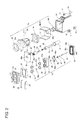
Fig. 2 is an exploded perspective view of the sealed contact device illustrated inFig. 1 ; -
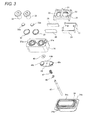
Fig. 3 is a partially enlarged perspective view of the sealed contact device illustrated inFig. 2 ; -
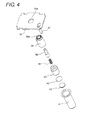
Fig. 4 is a partially enlarged perspective view of the sealed contact device illustrated inFig. 2 ; -
Fig. 5 is a partially enlarged perspective view of the sealed contact device illustrated inFig. 2 ; -
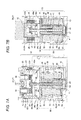
Fig. 6A and Fig. 6B are a front sectional view and a side sectional view illustrating a pre-operation of the sealed contact device illustrated inFig. 1 , respectively; -
Fig. 7A and Fig. 7B are a front sectional view and a side sectional view illustrating a post-operation of the sealed contact device illustrated inFig. 1 , respectively; and -
Fig. 8 is a partially enlarged sectional view ofFig. 6A . - The case where a sealed contact device according to an embodiment of the invention is applied to a sealed electromagnetic relay will be described with reference to
Fig. 1 to Fig. 8 .
In the sealed electromagnetic relay according to an embodiment of the invention, acontact mechanism unit 30 and anelectromagnet unit 50 are accommodated in a housing. The housing is formed by assembling acover 20 in acase 10. Thecontact mechanism unit 30 is incorporated in a sealed space including aceramic case 31, anannular flange 34, a plate-likefirst yoke 35, and a closed-end cylinder 41. Thecontact mechanism unit 30 is driven by theelectromagnet unit 50. - The
case 10 is a resin molding product having a substantially box shape. In thecase 10, a reinforcingring 13 is press-fitted in an attachinghole 12 in an attachingbase 11 that is projected outside of a corner portion. - The
cover 20 has a planar shape that can be fitted in an opening of thecase 10, andterminal holes partition wall 21 that is projected in the center of an upper surface of thecover 20.
Aholder 23 is fitted in an inside surface of thecover 20. Theholder 23 made of a magnetic material has a substantial U-shape when viewed from above.Permanent magnets arm portions holder 23. - In the
contact mechanism unit 30 fixediron core 36, amovable iron core 40, amovable shaft 45, andmovable touch piece 48 are incorporated in the sealed space including theceramic case 31 theannular flange 34, the plate-likefirst yoke 35, and the closed-end cylinder 41. - The
ceramic case 31 has the planar shape that can be fitted in an opening of thecase 10. As illustrated inFig. 3 , metallic layers (not illustrated) are formed in an upper-surface edge portion of a pair ofterminal holes ceramic case 31 and a lower end surface of theceramic case 31. As illustrated inFig. 6 andFig. 7 , afixed contact terminal 32 in which afixed contact 32a is rigidly fixed to a lower end portion is inserted in theterminal hole 31 a, and thefixed contact terminal 32 is brazed to theceramic case 31 with aconnection ring 33 interposed therebetween. - As illustrated in
Fig. 3 , in theannular flange 34 brazed to the lower end surface of theceramic case 31, a brazingannular projection 34b is provided along anannular step portion 34a formed by pressing a metallic plate, and a defensiveannular rib 34c is bent and raised inside the brazed annular projection 34b. in theannular flange 34, the lower end surface of theceramic case 31 is brazed to the brazedannular projection 34b, and an outer peripheral edge portion of theannular flange 34 is integrally welded to the upper surface of the plate-likefirst yoke 35. - As illustrated in
Fig. 4 , the upper end portion of the cylindrical fixediron core 36 is caulked to acenter hole 35a of the plate-likefirst yoke 35, and adegassing pipe 37 is coupled to an end portion of the plate-likefirst yoke 35 in a sealed manner. - The
movable shaft 45 is slidably inserted in the cylindrical fixediron core 36 while a stepped cylindrical insulatingmember 38 inserted in a through-hole 36a is interposed therebetween. Themovable shaft 45 inserted in the stepped cylindrical insulatingmember 38 is inserted in areturn spring 39, and themovable iron core 40 is welded to the lower end portion of themovable shaft 45. - In the closed-
end cylinder 41 in which themovable iron core 40 is accommodated, a shock absorber 42 and a stainless-steelthin plate 43 are accommodated in a bottom surface, and an opening edge portion is coupled to a lower-surface edge portion of thecenter hole 35a made in the plate-likefirst yoke 35 in the sealed manner, thereby forming a sealed space. - As illustrated in
Fig. 3 , themovable shaft 45 prevents drop-off of thecontact spring 47 andmovable touch piece 48 by anE ring 46 assembled in an upper portion of themovable shaft 45, and drop-off of themovable shaft 45 is prevented by a retainingring 49 caulked to the upper end portion of themovable shaft 45. Themovable contacts 48a provided in both end portions in the upper surface of themovable touch piece 48 are opposite the fixedcontact 32a disposed in theceramic case 31 so as to be brought into contact with and separated from thefixed contact 32a. - As illustrated in
Fig. 5 , in theelectromagnet unit 50, upper and lower end portions of aspool 52 around which acoil 51 is wound are covered withresin molding products coil 51 is connected to alead 55. The closed-end cylinder 41 is inserted in a through-hole 52 of thespool 52. Bothend portions second yoke 56 in which anauxiliary yoke 58 is assembled in acenter hole 56a are engaged in and fixed both the end portion of the plate-likefirst yoke 35, thereby integrating theelectromagnet unit 50 with thecontact mechanism unit 30. - An operation of the seated electromagnetic relay having the above-described configuration will be described below. When a voltage is not applied to the
coil 51, themovable iron core 40 is biased downward by a spring force of thereturn spring 39, thereby pressing down themovable shaft 45. Therefore, themovable touch piece 48 is dragged down, and themovable contact 48a is separated from the fixedcontact 32a. - When the voltage is applied to the
coil 51, themovable iron core 40 is attracted by the fixediron core 36, and themovable shaft 45 slide-moves against the spring force of thereturn spring 39. Even after themovable contact 48a comes into contact with the fixedcontact 32a, themovable shaft 45 is pushed up against the spring forces of thereturn spring 39 and contactspring 47, the upper end portion of themovable shaft 45 is projected from theshaft hole 48b of themovable touch piece 48, and themovable iron core 40 is stuck to the fixediron core 36. - When the application of the voltage to the
coil 51 is stopped to release magnetic excitation, themovable iron core 40 is separated from the fixediron core 36 based on the spring forces of thecontact spring 47 and returnspring 39. Therefore, themovable shaft 45 slide-moves downward, themovable contact 48a is separated from the fixedcontact 32a. Then themovable icon core 40 abuts on theshock absorber 42 with the stainless-steelthin plate 43 interposed therebetween, whereby themovable contact 48a returns to the original state. - According to the embodiment, as illustrated in
Fig. 8 , the brazed portion provided between theceramic case 31 and theannular projection 34b of theannular flange 34 is covered from the inside with theannular rib 34c provided in theannular flange 34. Therefore, even if the arc generated in separating themovable contact 48a from the fixedcontact 32a is attracted outward by the magnetic forces of thepermanent magnets - In the sealed contact device of the embodiment, an annular groove may be formed along an outside base portion of the
annular rib 34c of theannular flange 34 such that the lower end portion of theceramic case 31 can be fitted in the groove. The alignment work is facilitated by forming the annular groove, and advantageously the sealing performance is further improved while the assembling work is improved.
Obviously the annular projection may be provided in the bottom surface of the annular groove. - The sealed contact device of the invention is applied to not only the sealed electromagnetic relay but also other electromagnetic switches,
Claims (4)
- A sealed contact device, characterized in that an opening edge portion of a closed-ended cylinder (41) is integrated with lower-surface edge portion of a center hole (35a) made in a plate-like yoke (35) to form a sealed space while a lower end surface of a ceramic case (31) is brazed to an upper surface of an annular flange (34) whose outer peripheral edge portion is integrally welded to an upper surface of the plate-like yoke (35), a movable contact (48a) of a movable touch piece (48) fixed to one end portion of a movable shaft (45) is brought into contact with and separated from a fixed contact (32a) disposed in the ceramic case (31) by reciprocating the movable shaft (45) whose the other end is fixed to a movable iron core (40) reciprocating in the closed-ended cylinder (41) based on excitation and demagnetization of an electromagnetic unit (50) disposed in an outer periphery of the closed-ended cylinder (41) and an annular rib (34c) is projected in the upper surface of the annular flange (34) such that the brazed portion provided in the lower end surface of the ceramic case (31) is covered from an inside with the annular rib (34c).
- The sealed contact device according to claim 1, characterized in that an annular projection (34b) is provided in the upper surface of the annular flange (34), the annular projection (34b) being able to be brazed while abutting on the lower end surface of the ceramic case (31),
- The sealed contact device according to claim 1 or 2, characterized in that an annular groove is provided such that the lower end portion of the ceramic case (31) can be fitted on the upper surface of the annular flange (34).
- The sealed contact device as in any one of claims 1 to 3, characterized in that a cylindrical insulating member (38) is disposed between a cylindrical fixed iron core (36) and the movable shaft (45), the cylindrical fixed iron core (36) being disposed in the closed-end cylinder (41) and fixed to a lower surface of the plate-like yoke (35), the movable shaft (45) being inserted in the cylindrical fixed iron core (36) while being reciprocable.
Applications Claiming Priority (1)
| Application Number | Priority Date | Filing Date | Title |
|---|---|---|---|
| JP2010052043A JP5573250B2 (en) | 2010-03-09 | 2010-03-09 | Sealed contact device |
Publications (2)
| Publication Number | Publication Date |
|---|---|
| EP2365508A1 true EP2365508A1 (en) | 2011-09-14 |
| EP2365508B1 EP2365508B1 (en) | 2012-10-03 |
Family
ID=44123239
Family Applications (1)
| Application Number | Title | Priority Date | Filing Date |
|---|---|---|---|
| EP10196547A Active EP2365508B1 (en) | 2010-03-09 | 2010-12-22 | Sealed contact device |
Country Status (8)
| Country | Link |
|---|---|
| US (1) | US8198964B2 (en) |
| EP (1) | EP2365508B1 (en) |
| JP (1) | JP5573250B2 (en) |
| KR (1) | KR101175039B1 (en) |
| CN (1) | CN102194611B (en) |
| BR (1) | BRPI1100455A2 (en) |
| MY (1) | MY159674A (en) |
| RU (1) | RU2460165C1 (en) |
Cited By (4)
| Publication number | Priority date | Publication date | Assignee | Title |
|---|---|---|---|---|
| CN104810205A (en) * | 2014-01-23 | 2015-07-29 | 昆山国力真空电器有限公司 | Direct current contactor ceramic sealing improvement structure |
| DE102014004665A1 (en) * | 2014-03-31 | 2015-10-01 | Schaltbau Gmbh | Multi-pole contactor |
| EP2975626A1 (en) * | 2014-07-11 | 2016-01-20 | LSIS Co., Ltd. | Magnetic switch |
| EP3258476A1 (en) * | 2016-06-14 | 2017-12-20 | Fuji Electric FA Components & Systems Co., Ltd. | Contact device and electromagnetic contactor using the same |
Families Citing this family (35)
| Publication number | Priority date | Publication date | Assignee | Title |
|---|---|---|---|---|
| KR101357084B1 (en) | 2010-03-15 | 2014-02-03 | 오므론 가부시키가이샤 | Contact switching device |
| JP5488233B2 (en) * | 2010-06-11 | 2014-05-14 | 株式会社デンソー | Electromagnetic switch |
| KR101406357B1 (en) * | 2010-07-16 | 2014-06-12 | 파나소닉 주식회사 | Contact apparatus |
| KR101354405B1 (en) * | 2011-06-07 | 2014-01-22 | 후지쯔 콤포넌트 가부시끼가이샤 | Electromagnetic relay and manufacturing method therefor |
| JP5914065B2 (en) * | 2012-03-12 | 2016-05-11 | 富士電機機器制御株式会社 | Switch |
| JP5990028B2 (en) * | 2012-04-13 | 2016-09-07 | 富士電機機器制御株式会社 | Contact device and electromagnetic switch using the same |
| JP5938745B2 (en) * | 2012-07-06 | 2016-06-22 | パナソニックIpマネジメント株式会社 | Contact device and electromagnetic relay equipped with the contact device |
| CN104620348B (en) * | 2012-08-23 | 2017-05-17 | 松下知识产权经营株式会社 | Contact device |
| JP6064223B2 (en) * | 2012-12-28 | 2017-01-25 | パナソニックIpマネジメント株式会社 | Contact device and electromagnetic relay equipped with the contact device |
| DE102013210195A1 (en) * | 2013-05-31 | 2014-12-04 | Tyco Electronics Amp Gmbh | Arrangement for an electrical switching element and switching element |
| CN108417448B (en) * | 2013-06-28 | 2021-03-05 | 松下知识产权经营株式会社 | Contact device and electromagnetic relay having the same |
| JP6202943B2 (en) * | 2013-08-26 | 2017-09-27 | 富士通コンポーネント株式会社 | Electromagnetic relay |
| JP6265657B2 (en) * | 2013-08-26 | 2018-01-24 | 富士通コンポーネント株式会社 | Electromagnetic relay |
| CN104795278A (en) * | 2014-01-21 | 2015-07-22 | 昆山国力真空电器有限公司 | Sealing structure of DC contactor |
| KR101519784B1 (en) * | 2014-04-18 | 2015-05-12 | 현대자동차주식회사 | Battery relay for automobile |
| KR101626365B1 (en) * | 2014-09-30 | 2016-06-01 | 엘에스산전 주식회사 | Actuator for circuit breaker and method for manufacturing the same |
| KR101943363B1 (en) * | 2015-04-13 | 2019-04-17 | 엘에스산전 주식회사 | Magnetic Switch |
| KR101943364B1 (en) * | 2015-04-23 | 2019-04-17 | 엘에스산전 주식회사 | Magnetic Switch |
| KR20170009348A (en) * | 2015-07-16 | 2017-01-25 | 엘에스산전 주식회사 | Relay for electronic vehicle including permanent magnet and method of fabricating thereof |
| KR101943365B1 (en) * | 2015-10-14 | 2019-01-29 | 엘에스산전 주식회사 | Direct Relay |
| CN105513897A (en) * | 2016-01-10 | 2016-04-20 | 深圳巴斯巴科技发展有限公司 | Sealed type direct current contactor with high breaking capacity |
| JP6536472B2 (en) * | 2016-04-28 | 2019-07-03 | 株式会社デンソー | solenoid |
| KR102108894B1 (en) * | 2016-09-23 | 2020-05-11 | 엘에스일렉트릭(주) | Relay |
| DE102016121345B4 (en) * | 2016-11-08 | 2018-08-02 | Epcos Ag | Power contactor and method for producing a housing body for the power contactor |
| KR101888275B1 (en) * | 2016-12-23 | 2018-08-14 | 엘에스오토모티브테크놀로지스 주식회사 | Relay device |
| DE102017220503B3 (en) * | 2017-11-16 | 2019-01-17 | Te Connectivity Germany Gmbh | Double interrupting switch |
| KR20200000311A (en) * | 2018-08-31 | 2020-01-02 | 엘에스산전 주식회사 | Direct Current Relay |
| KR102324514B1 (en) * | 2018-08-31 | 2021-11-10 | 엘에스일렉트릭 (주) | Direct Current Relay |
| EP3879553B1 (en) * | 2018-11-09 | 2024-01-10 | Xiamen Hongfa Electric Power Controls Co., Ltd. | Direct-current relay resistant to short-circuit current |
| JP7036047B2 (en) * | 2019-01-18 | 2022-03-15 | オムロン株式会社 | relay |
| JP7351155B2 (en) * | 2019-09-13 | 2023-09-27 | オムロン株式会社 | electromagnetic relay |
| CN110853984A (en) * | 2019-12-06 | 2020-02-28 | 宁波天波港联电子有限公司 | Multi-section arc relay |
| JP7505213B2 (en) * | 2020-03-13 | 2024-06-25 | オムロン株式会社 | Electromagnetic Relay |
| PL4143867T3 (en) * | 2020-04-30 | 2026-03-09 | Xiamen Hongfa Electric Power Controls Co., Ltd. | High-voltage dc relay |
| KR20250017600A (en) * | 2023-07-27 | 2025-02-04 | 엘에스이모빌리티솔루션 주식회사 | Magnetic Contactor |
Citations (2)
| Publication number | Priority date | Publication date | Assignee | Title |
|---|---|---|---|---|
| EP0798752A2 (en) * | 1996-03-26 | 1997-10-01 | Matsushita Electric Works, Ltd. | Sealed contact device with contact gap adjustment capability |
| JPH09259728A (en) * | 1996-03-26 | 1997-10-03 | Matsushita Electric Works Ltd | Sealing contact device |
Family Cites Families (14)
| Publication number | Priority date | Publication date | Assignee | Title |
|---|---|---|---|---|
| SU838790A1 (en) * | 1979-09-07 | 1981-06-15 | Предприятие П/Я А-7374 | Sealed magnetically-operated switching device |
| JPS6326906Y2 (en) * | 1981-02-10 | 1988-07-21 | ||
| DE3537598A1 (en) * | 1985-10-23 | 1987-05-27 | Bosch Gmbh Robert | ELECTROMAGNETIC SWITCHES, IN PARTICULAR FOR TURNING DEVICES OF INTERNAL COMBUSTION ENGINES |
| DE3632469A1 (en) * | 1986-09-24 | 1988-03-31 | Bosch Gmbh Robert | ELECTROMAGNETIC SWITCHES, IN PARTICULAR FOR TURNING DEVICES OF INTERNAL COMBUSTION ENGINES |
| JP3690009B2 (en) | 1996-11-27 | 2005-08-31 | 松下電工株式会社 | Sealed contact device |
| FR2768259B1 (en) * | 1997-09-09 | 1999-10-08 | Valeo Equip Electr Moteur | STARTER CONTACTOR COMPRISING A SEALING PARTITION |
| DE19910148C2 (en) * | 1999-02-26 | 2001-03-22 | Siemens Ag | Vacuum interrupter with annular isolator |
| KR100505438B1 (en) * | 2001-11-29 | 2005-07-29 | 마츠시다 덴코 가부시키가이샤 | Electromagnetic switching device |
| JP2005026183A (en) | 2003-07-02 | 2005-01-27 | Matsushita Electric Works Ltd | Electromagnetic switching device |
| WO2006104080A1 (en) * | 2005-03-28 | 2006-10-05 | Matsushita Electric Works, Ltd. | Contact device |
| WO2007060945A1 (en) * | 2005-11-25 | 2007-05-31 | Matsushita Electric Works, Ltd. | Electromagnetic switch |
| KR20090119276A (en) * | 2008-05-15 | 2009-11-19 | 엘에스산전 주식회사 | Low noise electronic switch and its manufacturing method |
| JP5206157B2 (en) * | 2008-06-30 | 2013-06-12 | オムロン株式会社 | Electromagnetic relay |
| JP5163318B2 (en) * | 2008-06-30 | 2013-03-13 | オムロン株式会社 | Electromagnet device |
-
2010
- 2010-03-09 JP JP2010052043A patent/JP5573250B2/en active Active
- 2010-12-22 EP EP10196547A patent/EP2365508B1/en active Active
-
2011
- 2011-01-28 US US13/016,539 patent/US8198964B2/en active Active
- 2011-01-30 CN CN201110033331.1A patent/CN102194611B/en active Active
- 2011-02-10 KR KR1020110011695A patent/KR101175039B1/en active Active
- 2011-02-10 MY MYPI2011000595A patent/MY159674A/en unknown
- 2011-02-22 RU RU2011106655/07A patent/RU2460165C1/en not_active IP Right Cessation
- 2011-02-28 BR BRPI1100455-0A patent/BRPI1100455A2/en not_active IP Right Cessation
Patent Citations (3)
| Publication number | Priority date | Publication date | Assignee | Title |
|---|---|---|---|---|
| EP0798752A2 (en) * | 1996-03-26 | 1997-10-01 | Matsushita Electric Works, Ltd. | Sealed contact device with contact gap adjustment capability |
| JPH09259728A (en) * | 1996-03-26 | 1997-10-03 | Matsushita Electric Works Ltd | Sealing contact device |
| JP3107288B2 (en) | 1996-03-26 | 2000-11-06 | 松下電工株式会社 | Sealed contact device |
Cited By (8)
| Publication number | Priority date | Publication date | Assignee | Title |
|---|---|---|---|---|
| CN104810205A (en) * | 2014-01-23 | 2015-07-29 | 昆山国力真空电器有限公司 | Direct current contactor ceramic sealing improvement structure |
| DE102014004665A1 (en) * | 2014-03-31 | 2015-10-01 | Schaltbau Gmbh | Multi-pole contactor |
| US9799471B2 (en) | 2014-03-31 | 2017-10-24 | Schaltbau Gmbh | Multipolar power contactor |
| DE102014004665B4 (en) | 2014-03-31 | 2019-12-05 | Schaltbau Gmbh | Multi-pole contactor |
| EP2975626A1 (en) * | 2014-07-11 | 2016-01-20 | LSIS Co., Ltd. | Magnetic switch |
| US9754749B2 (en) | 2014-07-11 | 2017-09-05 | Lsis Co., Ltd. | Magnetic switch |
| EP3258476A1 (en) * | 2016-06-14 | 2017-12-20 | Fuji Electric FA Components & Systems Co., Ltd. | Contact device and electromagnetic contactor using the same |
| US10170261B2 (en) | 2016-06-14 | 2019-01-01 | Fuji Electric Fa Components & Systems Co., Ltd. | Contact device and electromagnetic contactor using same |
Also Published As
| Publication number | Publication date |
|---|---|
| JP5573250B2 (en) | 2014-08-20 |
| KR101175039B1 (en) | 2012-08-17 |
| US8198964B2 (en) | 2012-06-12 |
| RU2460165C1 (en) | 2012-08-27 |
| CN102194611A (en) | 2011-09-21 |
| EP2365508B1 (en) | 2012-10-03 |
| KR20110102155A (en) | 2011-09-16 |
| BRPI1100455A2 (en) | 2012-08-14 |
| JP2011187333A (en) | 2011-09-22 |
| CN102194611B (en) | 2014-09-24 |
| US20110221548A1 (en) | 2011-09-15 |
| MY159674A (en) | 2017-01-13 |
Similar Documents
| Publication | Publication Date | Title |
|---|---|---|
| EP2365508B1 (en) | Sealed contact device | |
| US8179217B2 (en) | Electromagnet device | |
| JP6910014B2 (en) | Contact device and electromagnetic relay equipped with the contact device | |
| EP2141724B1 (en) | Contact device | |
| CN109074993B (en) | Contact switching device and electromagnetic relay using the same | |
| CN104704594B (en) | Electromagnetic contactor | |
| EP2141714B1 (en) | Electromagnetic relay | |
| JP6003740B2 (en) | Electromagnetic relay | |
| US11011324B2 (en) | Contact device | |
| CN101443872A (en) | Electromagnetic relay and adjusting method and adjusting system thereof | |
| CN104221118A (en) | Electromagnetic contactor | |
| US11955302B2 (en) | Electromagnetic relay having embedded contact flush to terminal surface | |
| US12080500B2 (en) | Electromagnetic relay with seal between cantact case and drive device | |
| JP6064222B2 (en) | Contact device and electromagnetic relay equipped with the contact device | |
| JP6003771B2 (en) | Electromagnetic relay | |
| CN222813503U (en) | Relay |
Legal Events
| Date | Code | Title | Description |
|---|---|---|---|
| PUAI | Public reference made under article 153(3) epc to a published international application that has entered the european phase |
Free format text: ORIGINAL CODE: 0009012 |
|
| AK | Designated contracting states |
Kind code of ref document: A1 Designated state(s): AL AT BE BG CH CY CZ DE DK EE ES FI FR GB GR HR HU IE IS IT LI LT LU LV MC MK MT NL NO PL PT RO RS SE SI SK SM TR |
|
| AX | Request for extension of the european patent |
Extension state: BA ME |
|
| RAP1 | Party data changed (applicant data changed or rights of an application transferred) |
Owner name: OMRON CORPORATION |
|
| 17P | Request for examination filed |
Effective date: 20111207 |
|
| GRAP | Despatch of communication of intention to grant a patent |
Free format text: ORIGINAL CODE: EPIDOSNIGR1 |
|
| RIC1 | Information provided on ipc code assigned before grant |
Ipc: H01H 51/06 20060101ALN20120417BHEP Ipc: H01H 50/02 20060101ALN20120417BHEP Ipc: H01H 9/34 20060101ALN20120417BHEP Ipc: H01H 51/29 20060101AFI20120417BHEP |
|
| GRAS | Grant fee paid |
Free format text: ORIGINAL CODE: EPIDOSNIGR3 |
|
| GRAA | (expected) grant |
Free format text: ORIGINAL CODE: 0009210 |
|
| AK | Designated contracting states |
Kind code of ref document: B1 Designated state(s): AL AT BE BG CH CY CZ DE DK EE ES FI FR GB GR HR HU IE IS IT LI LT LU LV MC MK MT NL NO PL PT RO RS SE SI SK SM TR |
|
| REG | Reference to a national code |
Ref country code: GB Ref legal event code: FG4D |
|
| REG | Reference to a national code |
Ref country code: AT Ref legal event code: REF Ref document number: 578319 Country of ref document: AT Kind code of ref document: T Effective date: 20121015 Ref country code: CH Ref legal event code: EP |
|
| REG | Reference to a national code |
Ref country code: IE Ref legal event code: FG4D |
|
| REG | Reference to a national code |
Ref country code: DE Ref legal event code: R096 Ref document number: 602010003064 Country of ref document: DE Effective date: 20121129 |
|
| REG | Reference to a national code |
Ref country code: DE Ref legal event code: R082 Ref document number: 602010003064 Country of ref document: DE Representative=s name: KILIAN KILIAN & PARTNER MBB PATENTANWAELTE, DE Ref country code: DE Ref legal event code: R082 Ref document number: 602010003064 Country of ref document: DE Representative=s name: KILIAN KILIAN & PARTNER, DE |
|
| REG | Reference to a national code |
Ref country code: AT Ref legal event code: MK05 Ref document number: 578319 Country of ref document: AT Kind code of ref document: T Effective date: 20121003 |
|
| PG25 | Lapsed in a contracting state [announced via postgrant information from national office to epo] |
Ref country code: SI Free format text: LAPSE BECAUSE OF FAILURE TO SUBMIT A TRANSLATION OF THE DESCRIPTION OR TO PAY THE FEE WITHIN THE PRESCRIBED TIME-LIMIT Effective date: 20121003 |
|
| REG | Reference to a national code |
Ref country code: NL Ref legal event code: VDEP Effective date: 20121003 |
|
| REG | Reference to a national code |
Ref country code: LT Ref legal event code: MG4D |
|
| PG25 | Lapsed in a contracting state [announced via postgrant information from national office to epo] |
Ref country code: HR Free format text: LAPSE BECAUSE OF FAILURE TO SUBMIT A TRANSLATION OF THE DESCRIPTION OR TO PAY THE FEE WITHIN THE PRESCRIBED TIME-LIMIT Effective date: 20121003 Ref country code: NO Free format text: LAPSE BECAUSE OF FAILURE TO SUBMIT A TRANSLATION OF THE DESCRIPTION OR TO PAY THE FEE WITHIN THE PRESCRIBED TIME-LIMIT Effective date: 20130103 Ref country code: NL Free format text: LAPSE BECAUSE OF FAILURE TO SUBMIT A TRANSLATION OF THE DESCRIPTION OR TO PAY THE FEE WITHIN THE PRESCRIBED TIME-LIMIT Effective date: 20121003 Ref country code: SE Free format text: LAPSE BECAUSE OF FAILURE TO SUBMIT A TRANSLATION OF THE DESCRIPTION OR TO PAY THE FEE WITHIN THE PRESCRIBED TIME-LIMIT Effective date: 20121003 Ref country code: IS Free format text: LAPSE BECAUSE OF FAILURE TO SUBMIT A TRANSLATION OF THE DESCRIPTION OR TO PAY THE FEE WITHIN THE PRESCRIBED TIME-LIMIT Effective date: 20130203 Ref country code: LT Free format text: LAPSE BECAUSE OF FAILURE TO SUBMIT A TRANSLATION OF THE DESCRIPTION OR TO PAY THE FEE WITHIN THE PRESCRIBED TIME-LIMIT Effective date: 20121003 Ref country code: FI Free format text: LAPSE BECAUSE OF FAILURE TO SUBMIT A TRANSLATION OF THE DESCRIPTION OR TO PAY THE FEE WITHIN THE PRESCRIBED TIME-LIMIT Effective date: 20121003 |
|
| PG25 | Lapsed in a contracting state [announced via postgrant information from national office to epo] |
Ref country code: GR Free format text: LAPSE BECAUSE OF FAILURE TO SUBMIT A TRANSLATION OF THE DESCRIPTION OR TO PAY THE FEE WITHIN THE PRESCRIBED TIME-LIMIT Effective date: 20130104 Ref country code: LV Free format text: LAPSE BECAUSE OF FAILURE TO SUBMIT A TRANSLATION OF THE DESCRIPTION OR TO PAY THE FEE WITHIN THE PRESCRIBED TIME-LIMIT Effective date: 20121003 Ref country code: BE Free format text: LAPSE BECAUSE OF FAILURE TO SUBMIT A TRANSLATION OF THE DESCRIPTION OR TO PAY THE FEE WITHIN THE PRESCRIBED TIME-LIMIT Effective date: 20121003 Ref country code: PL Free format text: LAPSE BECAUSE OF FAILURE TO SUBMIT A TRANSLATION OF THE DESCRIPTION OR TO PAY THE FEE WITHIN THE PRESCRIBED TIME-LIMIT Effective date: 20121003 Ref country code: PT Free format text: LAPSE BECAUSE OF FAILURE TO SUBMIT A TRANSLATION OF THE DESCRIPTION OR TO PAY THE FEE WITHIN THE PRESCRIBED TIME-LIMIT Effective date: 20130204 |
|
| PG25 | Lapsed in a contracting state [announced via postgrant information from national office to epo] |
Ref country code: AT Free format text: LAPSE BECAUSE OF FAILURE TO SUBMIT A TRANSLATION OF THE DESCRIPTION OR TO PAY THE FEE WITHIN THE PRESCRIBED TIME-LIMIT Effective date: 20121003 |
|
| PG25 | Lapsed in a contracting state [announced via postgrant information from national office to epo] |
Ref country code: EE Free format text: LAPSE BECAUSE OF FAILURE TO SUBMIT A TRANSLATION OF THE DESCRIPTION OR TO PAY THE FEE WITHIN THE PRESCRIBED TIME-LIMIT Effective date: 20121003 Ref country code: SK Free format text: LAPSE BECAUSE OF FAILURE TO SUBMIT A TRANSLATION OF THE DESCRIPTION OR TO PAY THE FEE WITHIN THE PRESCRIBED TIME-LIMIT Effective date: 20121003 Ref country code: BG Free format text: LAPSE BECAUSE OF FAILURE TO SUBMIT A TRANSLATION OF THE DESCRIPTION OR TO PAY THE FEE WITHIN THE PRESCRIBED TIME-LIMIT Effective date: 20130103 Ref country code: MC Free format text: LAPSE BECAUSE OF NON-PAYMENT OF DUE FEES Effective date: 20121231 Ref country code: DK Free format text: LAPSE BECAUSE OF FAILURE TO SUBMIT A TRANSLATION OF THE DESCRIPTION OR TO PAY THE FEE WITHIN THE PRESCRIBED TIME-LIMIT Effective date: 20121003 Ref country code: RS Free format text: LAPSE BECAUSE OF FAILURE TO SUBMIT A TRANSLATION OF THE DESCRIPTION OR TO PAY THE FEE WITHIN THE PRESCRIBED TIME-LIMIT Effective date: 20121003 Ref country code: CZ Free format text: LAPSE BECAUSE OF FAILURE TO SUBMIT A TRANSLATION OF THE DESCRIPTION OR TO PAY THE FEE WITHIN THE PRESCRIBED TIME-LIMIT Effective date: 20121003 |
|
| PLBE | No opposition filed within time limit |
Free format text: ORIGINAL CODE: 0009261 |
|
| STAA | Information on the status of an ep patent application or granted ep patent |
Free format text: STATUS: NO OPPOSITION FILED WITHIN TIME LIMIT |
|
| PG25 | Lapsed in a contracting state [announced via postgrant information from national office to epo] |
Ref country code: RO Free format text: LAPSE BECAUSE OF FAILURE TO SUBMIT A TRANSLATION OF THE DESCRIPTION OR TO PAY THE FEE WITHIN THE PRESCRIBED TIME-LIMIT Effective date: 20121003 |
|
| 26N | No opposition filed |
Effective date: 20130704 |
|
| REG | Reference to a national code |
Ref country code: IE Ref legal event code: MM4A |
|
| PG25 | Lapsed in a contracting state [announced via postgrant information from national office to epo] |
Ref country code: ES Free format text: LAPSE BECAUSE OF FAILURE TO SUBMIT A TRANSLATION OF THE DESCRIPTION OR TO PAY THE FEE WITHIN THE PRESCRIBED TIME-LIMIT Effective date: 20130114 Ref country code: IE Free format text: LAPSE BECAUSE OF NON-PAYMENT OF DUE FEES Effective date: 20121222 |
|
| REG | Reference to a national code |
Ref country code: DE Ref legal event code: R097 Ref document number: 602010003064 Country of ref document: DE Effective date: 20130704 |
|
| PG25 | Lapsed in a contracting state [announced via postgrant information from national office to epo] |
Ref country code: CY Free format text: LAPSE BECAUSE OF FAILURE TO SUBMIT A TRANSLATION OF THE DESCRIPTION OR TO PAY THE FEE WITHIN THE PRESCRIBED TIME-LIMIT Effective date: 20121003 Ref country code: MT Free format text: LAPSE BECAUSE OF FAILURE TO SUBMIT A TRANSLATION OF THE DESCRIPTION OR TO PAY THE FEE WITHIN THE PRESCRIBED TIME-LIMIT Effective date: 20121003 Ref country code: AL Free format text: LAPSE BECAUSE OF FAILURE TO SUBMIT A TRANSLATION OF THE DESCRIPTION OR TO PAY THE FEE WITHIN THE PRESCRIBED TIME-LIMIT Effective date: 20121003 |
|
| PG25 | Lapsed in a contracting state [announced via postgrant information from national office to epo] |
Ref country code: TR Free format text: LAPSE BECAUSE OF FAILURE TO SUBMIT A TRANSLATION OF THE DESCRIPTION OR TO PAY THE FEE WITHIN THE PRESCRIBED TIME-LIMIT Effective date: 20121003 |
|
| PG25 | Lapsed in a contracting state [announced via postgrant information from national office to epo] |
Ref country code: SM Free format text: LAPSE BECAUSE OF FAILURE TO SUBMIT A TRANSLATION OF THE DESCRIPTION OR TO PAY THE FEE WITHIN THE PRESCRIBED TIME-LIMIT Effective date: 20121003 Ref country code: LU Free format text: LAPSE BECAUSE OF NON-PAYMENT OF DUE FEES Effective date: 20121222 |
|
| PG25 | Lapsed in a contracting state [announced via postgrant information from national office to epo] |
Ref country code: HU Free format text: LAPSE BECAUSE OF FAILURE TO SUBMIT A TRANSLATION OF THE DESCRIPTION OR TO PAY THE FEE WITHIN THE PRESCRIBED TIME-LIMIT Effective date: 20101222 |
|
| PG25 | Lapsed in a contracting state [announced via postgrant information from national office to epo] |
Ref country code: MK Free format text: LAPSE BECAUSE OF FAILURE TO SUBMIT A TRANSLATION OF THE DESCRIPTION OR TO PAY THE FEE WITHIN THE PRESCRIBED TIME-LIMIT Effective date: 20121003 |
|
| REG | Reference to a national code |
Ref country code: CH Ref legal event code: PL |
|
| GBPC | Gb: european patent ceased through non-payment of renewal fee |
Effective date: 20141222 |
|
| PG25 | Lapsed in a contracting state [announced via postgrant information from national office to epo] |
Ref country code: GB Free format text: LAPSE BECAUSE OF NON-PAYMENT OF DUE FEES Effective date: 20141222 Ref country code: LI Free format text: LAPSE BECAUSE OF NON-PAYMENT OF DUE FEES Effective date: 20141231 Ref country code: CH Free format text: LAPSE BECAUSE OF NON-PAYMENT OF DUE FEES Effective date: 20141231 |
|
| REG | Reference to a national code |
Ref country code: FR Ref legal event code: PLFP Year of fee payment: 6 |
|
| REG | Reference to a national code |
Ref country code: FR Ref legal event code: PLFP Year of fee payment: 7 |
|
| REG | Reference to a national code |
Ref country code: FR Ref legal event code: PLFP Year of fee payment: 8 |
|
| PGFP | Annual fee paid to national office [announced via postgrant information from national office to epo] |
Ref country code: FR Payment date: 20221110 Year of fee payment: 13 |
|
| PG25 | Lapsed in a contracting state [announced via postgrant information from national office to epo] |
Ref country code: FR Free format text: LAPSE BECAUSE OF NON-PAYMENT OF DUE FEES Effective date: 20231231 |
|
| PG25 | Lapsed in a contracting state [announced via postgrant information from national office to epo] |
Ref country code: FR Free format text: LAPSE BECAUSE OF NON-PAYMENT OF DUE FEES Effective date: 20231231 |
|
| PGFP | Annual fee paid to national office [announced via postgrant information from national office to epo] |
Ref country code: DE Payment date: 20251222 Year of fee payment: 16 |
|
| PGFP | Annual fee paid to national office [announced via postgrant information from national office to epo] |
Ref country code: IT Payment date: 20251231 Year of fee payment: 16 |