EP2365504A1 - Electrode for switch and vacuum switch, and method of manufacturing electrode for switch or vacuum switch - Google Patents
Electrode for switch and vacuum switch, and method of manufacturing electrode for switch or vacuum switch Download PDFInfo
- Publication number
- EP2365504A1 EP2365504A1 EP11002461A EP11002461A EP2365504A1 EP 2365504 A1 EP2365504 A1 EP 2365504A1 EP 11002461 A EP11002461 A EP 11002461A EP 11002461 A EP11002461 A EP 11002461A EP 2365504 A1 EP2365504 A1 EP 2365504A1
- Authority
- EP
- European Patent Office
- Prior art keywords
- electrode
- contact point
- switch
- groove
- conductor rod
- Prior art date
- Legal status (The legal status is an assumption and is not a legal conclusion. Google has not performed a legal analysis and makes no representation as to the accuracy of the status listed.)
- Granted
Links
- 238000004519 manufacturing process Methods 0.000 title claims description 21
- 239000004020 conductor Substances 0.000 claims abstract description 98
- 230000008878 coupling Effects 0.000 claims abstract description 86
- 238000010168 coupling process Methods 0.000 claims abstract description 86
- 238000005859 coupling reaction Methods 0.000 claims abstract description 86
- 230000002093 peripheral effect Effects 0.000 claims description 52
- 238000005219 brazing Methods 0.000 claims description 38
- 238000009413 insulation Methods 0.000 claims description 30
- 238000003780 insertion Methods 0.000 claims description 17
- 230000037431 insertion Effects 0.000 claims description 17
- 238000000034 method Methods 0.000 claims description 10
- UFHFLCQGNIYNRP-UHFFFAOYSA-N Hydrogen Chemical compound [H][H] UFHFLCQGNIYNRP-UHFFFAOYSA-N 0.000 claims description 7
- 238000006073 displacement reaction Methods 0.000 abstract description 7
- 230000009467 reduction Effects 0.000 abstract description 4
- 230000006872 improvement Effects 0.000 abstract description 2
- 230000005540 biological transmission Effects 0.000 abstract 1
- 239000000463 material Substances 0.000 description 19
- 239000000945 filler Substances 0.000 description 18
- 239000002184 metal Substances 0.000 description 11
- 229910052751 metal Inorganic materials 0.000 description 11
- 239000007789 gas Substances 0.000 description 4
- 230000000694 effects Effects 0.000 description 3
- 150000002739 metals Chemical class 0.000 description 2
- 238000007789 sealing Methods 0.000 description 2
- RYGMFSIKBFXOCR-UHFFFAOYSA-N Copper Chemical compound [Cu] RYGMFSIKBFXOCR-UHFFFAOYSA-N 0.000 description 1
- 229910052802 copper Inorganic materials 0.000 description 1
- 239000010949 copper Substances 0.000 description 1
- 230000007613 environmental effect Effects 0.000 description 1
- 230000017525 heat dissipation Effects 0.000 description 1
- 239000012774 insulation material Substances 0.000 description 1
- 238000002844 melting Methods 0.000 description 1
- 230000008018 melting Effects 0.000 description 1
- 239000007769 metal material Substances 0.000 description 1
- 238000012986 modification Methods 0.000 description 1
- 230000004048 modification Effects 0.000 description 1
- 238000010792 warming Methods 0.000 description 1
Images



Classifications
-
- H—ELECTRICITY
- H01—ELECTRIC ELEMENTS
- H01H—ELECTRIC SWITCHES; RELAYS; SELECTORS; EMERGENCY PROTECTIVE DEVICES
- H01H33/00—High-tension or heavy-current switches with arc-extinguishing or arc-preventing means
- H01H33/60—Switches wherein the means for extinguishing or preventing the arc do not include separate means for obtaining or increasing flow of arc-extinguishing fluid
- H01H33/66—Vacuum switches
-
- H—ELECTRICITY
- H01—ELECTRIC ELEMENTS
- H01H—ELECTRIC SWITCHES; RELAYS; SELECTORS; EMERGENCY PROTECTIVE DEVICES
- H01H33/00—High-tension or heavy-current switches with arc-extinguishing or arc-preventing means
- H01H33/60—Switches wherein the means for extinguishing or preventing the arc do not include separate means for obtaining or increasing flow of arc-extinguishing fluid
- H01H33/66—Vacuum switches
- H01H33/664—Contacts; Arc-extinguishing means, e.g. arcing rings
-
- H—ELECTRICITY
- H01—ELECTRIC ELEMENTS
- H01H—ELECTRIC SWITCHES; RELAYS; SELECTORS; EMERGENCY PROTECTIVE DEVICES
- H01H11/00—Apparatus or processes specially adapted for the manufacture of electric switches
- H01H11/04—Apparatus or processes specially adapted for the manufacture of electric switches of switch contacts
- H01H11/041—Apparatus or processes specially adapted for the manufacture of electric switches of switch contacts by bonding of a contact marking face to a contact body portion
-
- H—ELECTRICITY
- H01—ELECTRIC ELEMENTS
- H01H—ELECTRIC SWITCHES; RELAYS; SELECTORS; EMERGENCY PROTECTIVE DEVICES
- H01H33/00—High-tension or heavy-current switches with arc-extinguishing or arc-preventing means
- H01H33/60—Switches wherein the means for extinguishing or preventing the arc do not include separate means for obtaining or increasing flow of arc-extinguishing fluid
- H01H33/66—Vacuum switches
- H01H33/662—Housings or protective screens
- H01H33/66207—Specific housing details, e.g. sealing, soldering or brazing
-
- H—ELECTRICITY
- H01—ELECTRIC ELEMENTS
- H01H—ELECTRIC SWITCHES; RELAYS; SELECTORS; EMERGENCY PROTECTIVE DEVICES
- H01H11/00—Apparatus or processes specially adapted for the manufacture of electric switches
- H01H11/04—Apparatus or processes specially adapted for the manufacture of electric switches of switch contacts
- H01H11/041—Apparatus or processes specially adapted for the manufacture of electric switches of switch contacts by bonding of a contact marking face to a contact body portion
- H01H11/045—Apparatus or processes specially adapted for the manufacture of electric switches of switch contacts by bonding of a contact marking face to a contact body portion with the help of an intermediate layer
-
- H—ELECTRICITY
- H01—ELECTRIC ELEMENTS
- H01H—ELECTRIC SWITCHES; RELAYS; SELECTORS; EMERGENCY PROTECTIVE DEVICES
- H01H33/00—High-tension or heavy-current switches with arc-extinguishing or arc-preventing means
- H01H33/60—Switches wherein the means for extinguishing or preventing the arc do not include separate means for obtaining or increasing flow of arc-extinguishing fluid
- H01H33/66—Vacuum switches
- H01H33/664—Contacts; Arc-extinguishing means, e.g. arcing rings
- H01H33/6643—Contacts; Arc-extinguishing means, e.g. arcing rings having disc-shaped contacts subdivided in petal-like segments, e.g. by helical grooves
-
- Y—GENERAL TAGGING OF NEW TECHNOLOGICAL DEVELOPMENTS; GENERAL TAGGING OF CROSS-SECTIONAL TECHNOLOGIES SPANNING OVER SEVERAL SECTIONS OF THE IPC; TECHNICAL SUBJECTS COVERED BY FORMER USPC CROSS-REFERENCE ART COLLECTIONS [XRACs] AND DIGESTS
- Y10—TECHNICAL SUBJECTS COVERED BY FORMER USPC
- Y10T—TECHNICAL SUBJECTS COVERED BY FORMER US CLASSIFICATION
- Y10T29/00—Metal working
- Y10T29/49—Method of mechanical manufacture
- Y10T29/49002—Electrical device making
- Y10T29/49105—Switch making
Definitions
- the present invention relates to an electrode for a switch and a vacuum switch, and a method of manufacturing the electrode for the switch or the vacuum switch.
- the vacuum switch employs a vacuum insulation having a high insulation performance, and does not use a gas such as SF 6 or the like having a high global warming coefficient, it is a switch which can achieve both downsizing and reduction of an environmental load.
- the vacuum switch carries out an electric current break or the like in an inner portion of a vacuum vessel, however, a method of manufacturing the vacuum vessel in a high vacuum exists as a method of manufacturing the vacuum vessel.
- a method of manufacturing the vacuum vessel in a high vacuum exists as a method of manufacturing the vacuum vessel.
- a first step is a step of connecting metals to each other such as a connection between an electrode and a conducting bar
- a second step is a step of including the members adhered in accordance with the first step in an inner portion, connecting an insulation tube and a metal end plate, and constructing a vacuum sealed vacuum vessel.
- the first step is structured such as to connect the metals to each other, however, the second step has to connect the insulation material and the metal. Accordingly, it is necessary to use different brazing filler materials, respectively.
- the brazing filler material used in the first step is again molten in the second step, and if the brazing filler material is molten in the second step, the brazing filler material used for connecting the electrode and the conducting rod in the first step is deformed, so that there is a possibility that an air gap is generated between the electrode and the conductor rod, and a displacement is generated between the electrode and the conducting rod.
- patent document 1 JP-A-S-298971 .
- the patent document 1 has a description of an electrode which has an electrode rod provided with protruding portions 6a and 7a in an end portion, and an insertion hole having the same shape as the end portion of the electrode rod, and in which grooves 4a and 5b are formed in an inner portion, and describes an assembling method of the electrode rod and the electrode for finishing an assembly by setting a brazing filler material to a joint position between the electrode rod and the electrode, inserting the electrode rod to an electrode rod insertion port of the electrode, and rotating at about 90 degree in such a manner as to guide the protruding portions 6a and 7a of the end portion of the electrode rod to a groove in an inner portion of the electrode and locking, as an assembling method of the electrode rod and the electrode (paragraph [0008] to [0009] of the specification of the patent document 1.) Further, there is described that
- the air gap portion is occupied with an insulation medium such as a vacuum or the like. Since this portion exhibits a high insulating property, this portion comes to a high resistance portion at a time of conducting an electric current, and a conducting property of the electric current is lowered.
- a coefficient of thermal conductivity is lower in the air gap portion (for example, filled with a vapor or a gas in the case of an air brake insulation switch, filled with a gas in the case of a gas insulation switch, and filled with a vacuum in the case of a vacuum insulation switch, respectively) in comparison with the electrode corresponding to the metal material, and a heat conduction is prevented in the air gap portion, the electrode coming to a high temperature at a time when the electric current is broken is hard to be radiated heat, and a possibility that the electrode member is molten becomes higher. There is a risk that they cause a reduction of a reliability.
- the protruding portion of the end portion of the electrode rod is rotated and locked in such a manner as to be guided to the groove in the inner portion of the electrode, however, on the assumption that the assembling method mentioned above is achieved, it is necessary that a clearance gap is provided to some extent between the protruding portion of the end portion of the electrode rod and the groove in the inner portion of the electrode. In the case that no clearance gap is provided, the protruding portion of the end portion of the electrode rod can not be rotated with respect to the groove in the inner portion of the electrode. Further, the clearance gap corresponds to the air gap portion mentioned above eventually. Accordingly, in the case of intending to fix the electrode rod and the electrode on the basis of a rotation, it is unavoidable that an air gap portion exists to some extent or is enlarged.
- an object of the present invention is to provide an electrode or a switch which can improve a reliability of the switch, or a method of manufacturing the electrode for the switch or a vacuum switch.
- an electrode for a switch including a conductor rod, a contact point electrode inserted to the conductor rod, and a coupling plate fixing both the elements to an outer side in a diametrical direction of the conductor rod and the contact point electrode.
- the conductor rod is provided with a groove in a diametrical direction in an outer peripheral portion
- the contact point electrode is provided with a groove in a diametrical direction in an outer peripheral portion
- the coupling plate is fitted to the groove in the diametrical direction which the conductor rod has its outer peripheral portion, and the groove in the diametrical direction which the contact point electrode has its outer peripheral portion, and fixes the conductor rod and the contact point electrode.
- the coupling plate is provided with a groove in a diametrical direction in an outer peripheral portion
- the contact point electrode is provided with a groove positioned in the same circumference as the groove which the coupling plate is provided in the diametrical direction in its outer peripheral portion, at a position except the outer peripheral portion to which the coupling plate is fitted, in the outer peripheral portion
- the coupling plate is provided with a fixing member fitted to the groove in the diametrical direction which the coupling plate is provided in its outer peripheral portion
- the groove which the contact point electrode is provided in its outer peripheral portion, the groove being positioned in the same circumference as the groove which the coupling plate is provided in the diametrical direction in its outer peripheral portion.
- the coupling plate is provided with a flexibility.
- the coupling plate and/or the fixing member is constructed by a plurality of members.
- the contact point electrode is provided with a spiral groove at a position except a portion lapping over the conductor rod, in an axial direction of the conductor rod.
- a vacuum switch including the electrode for the switch in accordance with the present invention, and an insulation tube and an end plate constructing a vacuum vessel in which an inner portion comes to vacuum, wherein the insulation tube and the end plate are brazed therebetween, and the electrode for the switch is stored in the inner portion of the vacuum vessel.
- a vacuum switch including a conductor rod having a groove in a diametrical direction in a part in an axial direction, a contact point electrode provided with an insertion hole to which the conductor rod is inserted, structured such that the conductor rod is inserted to the insertion hole, and having a groove in a diametrical direction in an outer peripheral portion, a coupling plate fitted to the groove in the diametrical direction which the conductor rod has, and the groove in the diametrical direction of the outer peripheral portion which the contact point electrode has, and fixing the conductor rod and the contact point electrode, and a vacuum vessel constructed by an insulation tube and a metallic end plate, connoting the conductor rod and the contact point electrode, and coming to vacuum in its inner portion, wherein a first brazing filler material is provided in a contact surface between the conductor rod and the contact point electrode, and a second brazing filler material is provided between the insulation tube and the metallic end plate.
- a vacuum switch including a conductor rod having a groove in a diametrical direction in a part in an axial direction, a contact point electrode provided with an insertion hole of the conductor rod, structured such that the conductor rod is inserted to the insertion hole, provided with concave portions at two positions or more in an outer peripheral portion, and structured such that a portion except the concave portions in the outer peripheral portion has a groove in a diametrical direction, a coupling plate fitted to the groove which the conductor rod has, and the concave portions which the contact point electrode has, and provided with a groove constructing the same circumference as the groove which the contact point electrode has in the portion except the concave portions in the outer peripheral portion, in the portion fitted to the concave portions which the contact point electrode has, a ring pin fitted to the groove which the contact point electrode has in its outer peripheral portion and the groove which the coupling plate is provided, and fixing the contact point electrode and the coupling plate, and a vacuum
- the coupling plate is provided with a flexibility.
- the coupling plate is separated into two or more sections.
- the contact point electrode is provided with spiral grooves at two positions or more in a portion except a portion lapping over the conductor rod, in an axial direction of the conductor rod.
- a vacuum switch including the vacuum switch in accordance with the present invention, a cable feeding an electric power to a load side, a bus bar feeding an electric power to the vacuum switch, and an operation device opening and closing the vacuum switch.
- a method of manufacturing an electrode for a switch including a step of inserting a conductor rod to an electrode having an insertion hole, and thereafter fitting a coupling plate to an outer side in a diametrical direction of the conductor rod and the contact point electrode.
- a groove in a diametrical direction is formed in an outer peripheral portion in the coupling plate, and a groove positioned in the same circumferential shape as the groove which the coupling plate is provided in the diametrical direction in its outer peripheral portion, is formed at a position except the outer peripheral portion to which the coupling plate is fitted, in the outer peripheral portion, in the contact point electrode, and the method has a step of fitting the coupling plate to an outer side in the diametrical direction of the conductor rod and the contact point electrode, and thereafter fitting a fixing member to the groove formed in the coupling plate and the groove formed in the contact point electrode, thereby fixing the coupling plate, the conductor rod and the contact point electrode.
- a method of manufacturing a vacuum switch including a step of brazing an insulation tube and an end plate under a vacuum or a hydrogen gas, while connoting the electrode for the switch, after the step mentioned above.
- the brazing step is constructed by only one brazing step under the vacuum or the hydrogen gas.
- the electrode or the switch which can improve a reliability of the switch, or the method of manufacturing the electrode for the switch or the vacuum switch.
- a vacuum switch gear in accordance with the present embodiment is mainly constructed by a vacuum switch 70, a cable 71 feeding an electric power to a load side, a bus bar 72 feeding an electric power to a vacuum switch, and an operation device 73 opening, closing and disconnecting the vacuum switch 70.
- the vacuum switch 70 is constructed by an insulation tube 74 and a metal end plate 75, and is mainly constructed by a vacuum vessel in which an inner portion is set to vacuum, and conductor rods 1 and contact point electrodes 2 in a fixed side and a movable side which are connoted in the vacuum vessel.
- the cylindrical conductor rod 1 constructed by a copper member is inserted to an insertion hole corresponding to a shape of the conductor rod 1 provided in an inner side of the contact point electrode 2, and a first brazing filler material used in a first step is provided between the conductor rod 1 and the contact point electrode 2, whereby the conductor rod 1 and the contact point electrode 2 are fixed with no clearance gap.
- the contact point electrode 2 there is formed a region (a second groove 2b) in which an outer diameter 2b' is smaller than an outer diameter 2c' of the other region in the axial direction.
- the conductor rod 1 and the contact point electrode 2 are coupled by two coupling plates 3 and 4 which are formed as a semicircular shape by an elastic member, for example, SUS or the like, to the first groove and the second groove.
- the coupling plates 3 and 4 formed as the semicircular shape at this time are formed as the semicircular shape as shown in Fig.
- these coupling plates 3 and 4 by forming an inner diameter of the coupling plate having a circular shape equal to or larger than an outer diameter 1b' of the first groove 1b of the conductor rod 1 as shown in a cross sectional view in Fig. 1 , forming the outer diameters of the semicircular coupling plates 3 and 4 equal to or larger than an outer diameter 2c' of the region except the groove 2b of the contact point electrode 2, thereafter dividing the circular coupling plate into two or more in a diametrical direction. Further, these coupling plates 3 and 4 are formed by a material having an excellent elasticity in such a manner as to be freely fitted.
- a first brazing filler material is provided in a contact surface between the conductor rod 1 and the contact point electrode 2, and the conductor rod 1 is inserted to the insertion hole of the contact point electrode 2 as shown in Fig. 5 .
- inner peripheral end portions 3a and 4a of the coupling plates 3 and 4 are freely fitted in a radial direction to the first groove 1b of the conductor rod 1 as shown in Figs.
- a sealing of the vacuum vessel is completed by brazing the insulation tube 74 and the metal end plate 75 while connoting the conductor rod 1 and the contact point electrode 2 which have been fixed as mentioned above, under a high vacuum or a hydrogen gas.
- the first brazing filler material provided in the contact surface between the conductor rod 1 and the contact point electrode 2 is molten, and is simultaneously brazed.
- the present embodiment since the conductor rod 1 and the contact point electrode 2 are fixed by using the coupling plates 3 and 4, and a rotating motion is not used for fixing, it is possible to fix both the elements without generating any air gap in the center portion of the electrode and the conductor in which an electric current is conducted.
- the present embodiment is described as the embodiment about the vacuum switch gear including the electrode and the vacuum switch, as a matter of convenience, however, the invention itself can be realized as the electrode or the vacuum switch independently.
- the brazing step can be constructed only one step for brazing the insulation tube 74 and the metal end plate 75. This means that it is possible to omit the partially assembling step which has been conventionally carried out, by carrying out the fixing between the conductor rod 1 and the contact point electrode 2 by using the coupling plates 3 and 4. Accordingly, it is possible to achieve a wide improvement of a working efficiency.
- the brazing of the conductor rod 1 and the contact point electrode 2 can be carried out at the same time of the brazing step of the insulation tube 74 and the metal end plate 75, it is possible to prevent the positional displacement between the conductor rod 1 and the contact point electrode 2 which are brazed in the first step from being generated in the second step.
- the positional displacement of the electrode causes a contact failure between the electrodes. In the case that the contact failure is generated, a non-contact portion between the electrodes comes to a high resistance portion due to a vacuum insulation, whereby an equipment performance of the switch is significantly deteriorated.
- the conduction is generated, it is a contact by an arc so as to cause a melting of the electrode portion, and there is a risk that a reduction of a service life of the equipment is caused.
- the present embodiment is very useful in a point that the positional displacement of the electrode can be prevented.
- the contact point electrode 2 comes to a high temperature because of generation of an arc at a time of opening and closing, and is demanded to be heat radiated as soon as possible in the light of preventing the electrode from being molten.
- the air gap is generated within the electrode, and the vacuum portion having a significantly small coefficient of thermal conductivity in comparison with the metal is generated, a heat dissipation performance is lowered, and there is a possibility that the electrode is molten.
- the electrode surface becomes non-flat, thereby causing the arc at a time of opening and closing on and after the next time.
- the electric current of 25 kA is applied within the switch for about three second, the temperature of the electrode portion reaches 300 K, however, in accordance with the present embodiment, since the air gap is not generated in the conduction portion within the electrode, it is possible to hold down a temperature rise to 240 K, and it is possible to reduce a thermal loss at about 20 %. Further, it is possible to prevent the electrode surface from being molten, and it is possible to reduce the generation of the art at a time of opening and closing.
- the coupling plates 3 and 4 in the present embodiment are constructed by the member having the flexibility, for example, SUS or the like, a flexibility at a time of being fitted to the conductor rod 1 and the contact point electrode 2 is increased, and it becomes easy to fit at a time of coming into contact with the conductor rod 1 and the contact point electrode 2.
- the coupling plates 3 and 4 are divided into two sections, however, may be formed as one unit, or may be divided into three or more sections. At this time, if they are arranged uniformly in the diametrical direction, an incline or the like is not generated, and a stability for fixing is improved. Arranging uniformly in the diametrical direction indicates a case that a plurality of coupling plates are used and are arranged approximately symmetrically in a peripheral direction.
- the contact electrode 2 is provided with concave portions (grooves) 52c at two positions in an upper end portion of the electrode, as shown in Fig. 9 .
- a convex portion 52b having no concavity is provided on the same circumference as the concave portion 52c.
- a groove 53 is formed on an outer peripheral surface of the concave portion 52b.
- the coupling plates 3 and 4 in the present embodiment are provided with a fitting portion 4c in such a manner as to correspond to the concave portion 52c of the contact point electrode 2, and a portion fitted to the conductor rod 1 is structured in the same manner as the first embodiment.
- the fitting portion 4c provided in the coupling plates 3 and 4 there is formed a groove 60 constructing the same circumference as the groove 53 formed in the convex portion 52b of the contact point electrode 2 at a time of being fitted to the contact point electrode 2.
- the contact point electrode 2 and the coupling plates 3 and 4 are fixed by fitting a ring pin 5 to the grooves 53 and the groove 60.
- the ring pin 5 is provided with a cut at an angle of circumference equal to or more than 5 degree from a center of the ring pin 5 in such a manner as to be fitted to the groove.
- the angle is set to be equal to or more than 5 degree because it is necessary to temporarily expand at a time of fitting the ring pin 5 to the contact point electrode and the coupling plate, and it becomes further easy to expand at that time if the angle is equal to or more than 5 degree.
- the other portions than the portion mentioned above are the same as those of the first embodiment, and an overlapping description will be omitted.
- the present embodiment can achieve the same effect as that of the first embodiment.
- ring pin 5 in the case that only one ring pin is provided, in the present embodiment, however, a structure in which it is separated into a plurality of pins is not excluded.
- the contact point electrode 2 is provide with the concave portions at two positions, however, may be provided at three positions or more. Further, there can be thought that two or more ring pins are used for fixing. In the case mentioned above, it goes without saying that it is necessary to increase the number of the grooves provided in the contact point electrode and the coupling plate in correspondence thereto.
- spiral electrode in which a hole 2d having a diameter equal to or less than an inner diameter of the contact point electrode is formed in the center portion close to the contact point shown in Fig. 1 , and spiral grooves 2e are provided at two or more positions in the position except the portion lapping over a conductor outer diameter 1c' of the electrode center portion in the axial direction.
- the spiral groove 2e can be formed by forming a cut from a start point 2e' of the groove to an end point 2e" of the groove.
- the air gap portion is not generated between the electrode and the conductor by applying the spiral electrode to the first and second embodiments, it is possible to prevent the warping of the electrode from the center of the spiral electrode to the end portion, by inserting the conductor to the vicinity of the contact point of the electrode, and a further effect can be achieved since a contact area of the contact point can be secured.
- the coupling plates 3 and 4 may be structured such as to fix to whichever position in the axial direction of the conductor rods.
- the vacuum switch includes a vacuum grounding switch aiming at grounding.
- the first and second embodiments can be applied to the vacuum grounding switch.
Landscapes
- Engineering & Computer Science (AREA)
- Manufacturing & Machinery (AREA)
- High-Tension Arc-Extinguishing Switches Without Spraying Means (AREA)
Abstract
Description
- The present invention relates to an electrode for a switch and a vacuum switch, and a method of manufacturing the electrode for the switch or the vacuum switch.
- Since the vacuum switch employs a vacuum insulation having a high insulation performance, and does not use a gas such as SF6 or the like having a high global warming coefficient, it is a switch which can achieve both downsizing and reduction of an environmental load.
- The vacuum switch carries out an electric current break or the like in an inner portion of a vacuum vessel, however, a method of manufacturing the vacuum vessel in a high vacuum exists as a method of manufacturing the vacuum vessel. In this case, in a brazing in a manufacturing step of the vacuum vessel, it is necessary to properly use a brazing filler metal in correspondence to a material between members constructing the vacuum vessel. Accordingly, it is necessary to separate the brazing into at least two steps.
- A first step is a step of connecting metals to each other such as a connection between an electrode and a conducting bar, and a second step is a step of including the members adhered in accordance with the first step in an inner portion, connecting an insulation tube and a metal end plate, and constructing a vacuum sealed vacuum vessel. The first step is structured such as to connect the metals to each other, however, the second step has to connect the insulation material and the metal. Accordingly, it is necessary to use different brazing filler materials, respectively.
- Therefore, there is a possibility that the brazing filler material used in the first step is again molten in the second step, and if the brazing filler material is molten in the second step, the brazing filler material used for connecting the electrode and the conducting rod in the first step is deformed, so that there is a possibility that an air gap is generated between the electrode and the conductor rod, and a displacement is generated between the electrode and the conducting rod.
- In order to prevent the displacement between the electrode and the conducting rod as mentioned above from being generated, for example, there is a structure described in patent document 1 (
JP-A-S-298971 patent document 1 has a description of an electrode which has an electrode rod provided with protruding portions 6a and 7a in an end portion, and an insertion hole having the same shape as the end portion of the electrode rod, and in whichgrooves 4a and 5b are formed in an inner portion, and describes an assembling method of the electrode rod and the electrode for finishing an assembly by setting a brazing filler material to a joint position between the electrode rod and the electrode, inserting the electrode rod to an electrode rod insertion port of the electrode, and rotating at about 90 degree in such a manner as to guide the protruding portions 6a and 7a of the end portion of the electrode rod to a groove in an inner portion of the electrode and locking, as an assembling method of the electrode rod and the electrode (paragraph [0008] to [0009] of the specification of thepatent document 1.) Further, there is described that an object of the invention is to provide a vacuum valve which can prevent the electrode from coming off and being inclined and prevent a positional displacement between the electrode rod and the electrode in a final assembling step, and has a high reliability without lowering a performance serving as the vacuum valve, in the case that a brazing temperature in a partial assembling step is the same as a brazing temperature at which a vacuum sealing is carried out in a final assembling step (paragraph [0005] of the specification of the patent document 1). - In this case, in the case that an air gap is generated between the electrode and the conducting rod, the air gap portion is occupied with an insulation medium such as a vacuum or the like. Since this portion exhibits a high insulating property, this portion comes to a high resistance portion at a time of conducting an electric current, and a conducting property of the electric current is lowered. Further, since a coefficient of thermal conductivity is lower in the air gap portion (for example, filled with a vapor or a gas in the case of an air brake insulation switch, filled with a gas in the case of a gas insulation switch, and filled with a vacuum in the case of a vacuum insulation switch, respectively) in comparison with the electrode corresponding to the metal material, and a heat conduction is prevented in the air gap portion, the electrode coming to a high temperature at a time when the electric current is broken is hard to be radiated heat, and a possibility that the electrode member is molten becomes higher. There is a risk that they cause a reduction of a reliability.
- In the
patent document 1 mentioned above, the protruding portion of the end portion of the electrode rod is rotated and locked in such a manner as to be guided to the groove in the inner portion of the electrode, however, on the assumption that the assembling method mentioned above is achieved, it is necessary that a clearance gap is provided to some extent between the protruding portion of the end portion of the electrode rod and the groove in the inner portion of the electrode. In the case that no clearance gap is provided, the protruding portion of the end portion of the electrode rod can not be rotated with respect to the groove in the inner portion of the electrode. Further, the clearance gap corresponds to the air gap portion mentioned above eventually. Accordingly, in the case of intending to fix the electrode rod and the electrode on the basis of a rotation, it is unavoidable that an air gap portion exists to some extent or is enlarged. - Accordingly, an object of the present invention is to provide an electrode or a switch which can improve a reliability of the switch, or a method of manufacturing the electrode for the switch or a vacuum switch.
- In order to achieve the object mentioned above, in accordance with the present invention, there is provided an electrode for a switch including a conductor rod, a contact point electrode inserted to the conductor rod, and a coupling plate fixing both the elements to an outer side in a diametrical direction of the conductor rod and the contact point electrode.
- In the electrode for the switch in accordance with the present invention, it is preferable that the conductor rod is provided with a groove in a diametrical direction in an outer peripheral portion, the contact point electrode is provided with a groove in a diametrical direction in an outer peripheral portion, and the coupling plate is fitted to the groove in the diametrical direction which the conductor rod has its outer peripheral portion, and the groove in the diametrical direction which the contact point electrode has its outer peripheral portion, and fixes the conductor rod and the contact point electrode.
- Further, in the electrode for the switch in accordance with the present invention, it is preferable that the coupling plate is provided with a groove in a diametrical direction in an outer peripheral portion, the contact point electrode is provided with a groove positioned in the same circumference as the groove which the coupling plate is provided in the diametrical direction in its outer peripheral portion, at a position except the outer peripheral portion to which the coupling plate is fitted, in the outer peripheral portion, and the coupling plate is provided with a fixing member fitted to the groove in the diametrical direction which the coupling plate is provided in its outer peripheral portion, and the groove which the contact point electrode is provided in its outer peripheral portion, the groove being positioned in the same circumference as the groove which the coupling plate is provided in the diametrical direction in its outer peripheral portion.
- Further, in the electrode for the switch in accordance with the present invention, it is preferable that the coupling plate is provided with a flexibility.
- Further, in the electrode for the switch in accordance with the present invention, it is preferable that the coupling plate and/or the fixing member is constructed by a plurality of members.
- Further, in the electrode for the switch in accordance with the present invention, it is preferable that the contact point electrode is provided with a spiral groove at a position except a portion lapping over the conductor rod, in an axial direction of the conductor rod.
- Further, in accordance with the present invention, there is provided a vacuum switch including the electrode for the switch in accordance with the present invention, and an insulation tube and an end plate constructing a vacuum vessel in which an inner portion comes to vacuum, wherein the insulation tube and the end plate are brazed therebetween, and the electrode for the switch is stored in the inner portion of the vacuum vessel.
- In accordance with the present invention, there is provided a vacuum switch including a conductor rod having a groove in a diametrical direction in a part in an axial direction, a contact point electrode provided with an insertion hole to which the conductor rod is inserted, structured such that the conductor rod is inserted to the insertion hole, and having a groove in a diametrical direction in an outer peripheral portion, a coupling plate fitted to the groove in the diametrical direction which the conductor rod has, and the groove in the diametrical direction of the outer peripheral portion which the contact point electrode has, and fixing the conductor rod and the contact point electrode, and a vacuum vessel constructed by an insulation tube and a metallic end plate, connoting the conductor rod and the contact point electrode, and coming to vacuum in its inner portion, wherein a first brazing filler material is provided in a contact surface between the conductor rod and the contact point electrode, and a second brazing filler material is provided between the insulation tube and the metallic end plate.
- Further, in accordance with the present invention, there is provided a vacuum switch including a conductor rod having a groove in a diametrical direction in a part in an axial direction, a contact point electrode provided with an insertion hole of the conductor rod, structured such that the conductor rod is inserted to the insertion hole, provided with concave portions at two positions or more in an outer peripheral portion, and structured such that a portion except the concave portions in the outer peripheral portion has a groove in a diametrical direction, a coupling plate fitted to the groove which the conductor rod has, and the concave portions which the contact point electrode has, and provided with a groove constructing the same circumference as the groove which the contact point electrode has in the portion except the concave portions in the outer peripheral portion, in the portion fitted to the concave portions which the contact point electrode has, a ring pin fitted to the groove which the contact point electrode has in its outer peripheral portion and the groove which the coupling plate is provided, and fixing the contact point electrode and the coupling plate, and a vacuum vessel constructed by an insulation tube and a metallic end plate, connoting the conductor rod and the contact point electrode, and coming to vacuum in its inner portion, wherein a first brazing filler material is provided in a contact surface between the conductor rod and the contact point electrode, and a second brazing filler material is provided between the insulation tube and the metallic end plate.
- In the vacuum switch in accordance with the present invention, it is preferable that the coupling plate is provided with a flexibility.
- Further, in the vacuum switch in accordance with the present invention, it is preferable that the coupling plate is separated into two or more sections.
- Further, in the vacuum switch in accordance with the present invention, it is preferable that the contact point electrode is provided with spiral grooves at two positions or more in a portion except a portion lapping over the conductor rod, in an axial direction of the conductor rod.
- Further, in accordance with the present invention, there is provided a vacuum switch including the vacuum switch in accordance with the present invention, a cable feeding an electric power to a load side, a bus bar feeding an electric power to the vacuum switch, and an operation device opening and closing the vacuum switch.
- Further, in order to achieve the object mentioned above, in accordance with the present invention, there is provided a method of manufacturing an electrode for a switch, including a step of inserting a conductor rod to an electrode having an insertion hole, and thereafter fitting a coupling plate to an outer side in a diametrical direction of the conductor rod and the contact point electrode.
- In the method of manufacturing the electrode for the switch in accordance with the present invention, it is preferable that a groove in a diametrical direction is formed in an outer peripheral portion in the coupling plate, and a groove positioned in the same circumferential shape as the groove which the coupling plate is provided in the diametrical direction in its outer peripheral portion, is formed at a position except the outer peripheral portion to which the coupling plate is fitted, in the outer peripheral portion, in the contact point electrode, and the method has a step of fitting the coupling plate to an outer side in the diametrical direction of the conductor rod and the contact point electrode, and thereafter fitting a fixing member to the groove formed in the coupling plate and the groove formed in the contact point electrode, thereby fixing the coupling plate, the conductor rod and the contact point electrode.
- In accordance with the present invention, there is provided a method of manufacturing a vacuum switch including a step of brazing an insulation tube and an end plate under a vacuum or a hydrogen gas, while connoting the electrode for the switch, after the step mentioned above.
- In the method of manufacturing the vacuum switch in accordance with the present invention, it is preferable that the brazing step is constructed by only one brazing step under the vacuum or the hydrogen gas.
- In accordance with the present invention, it is possible to provide the electrode or the switch which can improve a reliability of the switch, or the method of manufacturing the electrode for the switch or the vacuum switch.
- Other objects, features and advantages of the invention will become apparent from the following description of the embodiments of the invention taken in conjunction with the accompanying drawings.
-
-
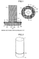
Fig. 1 is a cross sectional view in an axial direction of an electrode portion in accordance with a first embodiment; -
Fig. 2 is a view showing a conductor rod in accordance with the first embodiment; -
Fig. 3 is a view showing a contact point electrode in accordance with the first embodiment; -
Fig. 4 is a view showing a coupling plate in accordance with the first embodiment; -
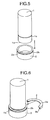
Fig. 5 is a view showing a state in which the conductor rod is inserted to the contact point electrode in accordance with the first embodiment; -
Fig. 6 is a view showing a state in which the coupling plate is fitted to the electrode portion in accordance with the first embodiment; -
Fig. 7 is a view showing a state in which the coupling plate is fitted to the electrode portion in accordance with the first embodiment; -
Fig. 8 is a view showing a substantial part of an electrode portion in accordance with a second embodiment; -
Fig. 9 is a view showing a contact point electrode in accordance with the second embodiment; -
Fig. 10 is a view showing a coupling plate in accordance with the second embodiment; -
Fig. 11 is a view showing a ring pin in accordance with the second embodiment; -
Fig. 12 is view showing a state in which a conductor rod is inserted to the contact point electrode in accordance with the second embodiment; -
Fig. 13 is a view showing a state in which the coupling plate is fitted to the electrode portion in accordance with the second embodiment; -
Fig. 14 is a view showing a state in which the coupling plate is fitted to the electrode portion in accordance with the second embodiment; -
Fig. 15 is a view showing a state in which the ring pin is fitted to the electrode portion in accordance with the second embodiment; -
Fig. 16 is a completion drawing of the electrode portion in accordance with the second embodiment; -
Fig. 17 is a cross sectional view of a vacuum switch gear; and -
Fig. 18 is an enlarged view of a vacuum switch. -
- 1
- conductor rod
- 1a
- leading end of
conductor rod 1 - 1b
- first groove
- 2
- contact point electrode
- 2a
- bottom portion of
contact point electrode 2 - 2b
- second groove
- 2c
- outer diameter of contact point electrode
- 2d
- hole in center portion of contact point electrode
- 2e
- spiral groove of contact point electrode
- 2e'
- start point of spiral groove of contact point electrode
- 2e"
- end point of spiral groove of contact point electrode
- 3, 4
- coupling plate
- 3a, 4a
- inner peripheral end portion of coupling plate
- 3b, 4b
- outer peripheral end portion of coupling plate
- 5
- ring pin
- 52b
- convex portion
- 52c
- concave portion
- 53,60
- groove
- 70
- vacuum switch
- 71
- cable
- 72
- bus bar
- 73
- operation device
- 74
- insulation tube
- 75
- end plate
- A description will be given below of an embodiment which is preferable for carrying out the present invention.
- A description will be given of a first embodiment in accordance with the present invention. As shown in
Figs. 17 and18 , a vacuum switch gear in accordance with the present embodiment is mainly constructed by avacuum switch 70, acable 71 feeding an electric power to a load side, abus bar 72 feeding an electric power to a vacuum switch, and anoperation device 73 opening, closing and disconnecting thevacuum switch 70. Further, thevacuum switch 70 is constructed by aninsulation tube 74 and ametal end plate 75, and is mainly constructed by a vacuum vessel in which an inner portion is set to vacuum, andconductor rods 1 andcontact point electrodes 2 in a fixed side and a movable side which are connoted in the vacuum vessel. - As shown in
Fig. 1 , thecylindrical conductor rod 1 constructed by a copper member is inserted to an insertion hole corresponding to a shape of theconductor rod 1 provided in an inner side of thecontact point electrode 2, and a first brazing filler material used in a first step is provided between theconductor rod 1 and thecontact point electrode 2, whereby theconductor rod 1 and thecontact point electrode 2 are fixed with no clearance gap. Further, in theconductor rod 1, there is formed a region (afirst groove 1b) in which anouter diameter 1b' is smaller than an outer diameter 1c' of the other region in an axial direction, above the region which is inserted to thecontact point electrode 2 of a cylinder shaft. Further, in thecontact point electrode 2, there is formed a region (asecond groove 2b) in which anouter diameter 2b' is smaller than anouter diameter 2c' of the other region in the axial direction. As shown inFig. 4 , theconductor rod 1 and thecontact point electrode 2 are coupled by twocoupling plates coupling plates Fig. 4 by forming an inner diameter of the coupling plate having a circular shape equal to or larger than anouter diameter 1b' of thefirst groove 1b of theconductor rod 1 as shown in a cross sectional view inFig. 1 , forming the outer diameters of thesemicircular coupling plates outer diameter 2c' of the region except thegroove 2b of thecontact point electrode 2, thereafter dividing the circular coupling plate into two or more in a diametrical direction. Further, thesecoupling plates - A description will be given of a method of manufacturing a vacuum switch using the electrode mentioned above with reference to
Figs. 5 to 7 . First of all, a first brazing filler material is provided in a contact surface between theconductor rod 1 and thecontact point electrode 2, and theconductor rod 1 is inserted to the insertion hole of thecontact point electrode 2 as shown inFig. 5 . After the insertion to the insertion hole, innerperipheral end portions coupling plates first groove 1b of theconductor rod 1 as shown inFigs. 6 and7 , and outerperipheral end portions coupling plates second groove 2b formed in thecontact point electrode 2 so as to fix theconductor rod 1 and thecontact point electrode 2. Since thecoupling plates conductor rod 1 and thecontact point electrode 2 are fixed. - Next, a sealing of the vacuum vessel is completed by brazing the
insulation tube 74 and themetal end plate 75 while connoting theconductor rod 1 and thecontact point electrode 2 which have been fixed as mentioned above, under a high vacuum or a hydrogen gas. In accordance with this brazing step, the first brazing filler material provided in the contact surface between theconductor rod 1 and thecontact point electrode 2 is molten, and is simultaneously brazed. In this case, it is necessary to set a second brazing filler material between theinsulation tube 74 and themetal end plate 75, before the present brazing step. - In the present embodiment, since the
conductor rod 1 and thecontact point electrode 2 are fixed by using thecoupling plates - Further, as a very advantageous point in the present embodiment, there can be listed up the matter that the brazing step can be constructed only one step for brazing the
insulation tube 74 and themetal end plate 75. This means that it is possible to omit the partially assembling step which has been conventionally carried out, by carrying out the fixing between theconductor rod 1 and thecontact point electrode 2 by using thecoupling plates - Further, since the brazing of the
conductor rod 1 and thecontact point electrode 2 can be carried out at the same time of the brazing step of theinsulation tube 74 and themetal end plate 75, it is possible to prevent the positional displacement between theconductor rod 1 and thecontact point electrode 2 which are brazed in the first step from being generated in the second step. The positional displacement of the electrode causes a contact failure between the electrodes. In the case that the contact failure is generated, a non-contact portion between the electrodes comes to a high resistance portion due to a vacuum insulation, whereby an equipment performance of the switch is significantly deteriorated. Further, even if the conduction is generated, it is a contact by an arc so as to cause a melting of the electrode portion, and there is a risk that a reduction of a service life of the equipment is caused. The present embodiment is very useful in a point that the positional displacement of the electrode can be prevented. - Further, in the case that the air gap is generated, a high resistance portion caused by the vacuum insulation is formed within the air gap. Accordingly, the performance as the equipment of the switch is significantly deteriorated. Further, the
contact point electrode 2 comes to a high temperature because of generation of an arc at a time of opening and closing, and is demanded to be heat radiated as soon as possible in the light of preventing the electrode from being molten. However, since the air gap is generated within the electrode, and the vacuum portion having a significantly small coefficient of thermal conductivity in comparison with the metal is generated, a heat dissipation performance is lowered, and there is a possibility that the electrode is molten. In the case that the electrode is molten, the electrode surface becomes non-flat, thereby causing the arc at a time of opening and closing on and after the next time. In the conventional case, in the case that the electric current of 25 kA is applied within the switch for about three second, the temperature of the electrode portion reaches 300 K, however, in accordance with the present embodiment, since the air gap is not generated in the conduction portion within the electrode, it is possible to hold down a temperature rise to 240 K, and it is possible to reduce a thermal loss at about 20 %. Further, it is possible to prevent the electrode surface from being molten, and it is possible to reduce the generation of the art at a time of opening and closing. - Since the
coupling plates conductor rod 1 and thecontact point electrode 2 is increased, and it becomes easy to fit at a time of coming into contact with theconductor rod 1 and thecontact point electrode 2. - Further, in the present embodiment, the
coupling plates - Next, a description will be given of a second embodiment in accordance with the present invention with reference to
Figs. 8 to 16 . In the present embodiment, thecontact electrode 2 is provided with concave portions (grooves) 52c at two positions in an upper end portion of the electrode, as shown inFig. 9 . Aconvex portion 52b having no concavity is provided on the same circumference as theconcave portion 52c. Agroove 53 is formed on an outer peripheral surface of theconcave portion 52b. Further, as shown inFig. 10 , thecoupling plates fitting portion 4c in such a manner as to correspond to theconcave portion 52c of thecontact point electrode 2, and a portion fitted to theconductor rod 1 is structured in the same manner as the first embodiment. Further, in thefitting portion 4c provided in thecoupling plates groove 60 constructing the same circumference as thegroove 53 formed in theconvex portion 52b of thecontact point electrode 2 at a time of being fitted to thecontact point electrode 2. Further, thecontact point electrode 2 and thecoupling plates ring pin 5 to thegrooves 53 and thegroove 60. In this case, thering pin 5 is provided with a cut at an angle of circumference equal to or more than 5 degree from a center of thering pin 5 in such a manner as to be fitted to the groove. The angle is set to be equal to or more than 5 degree because it is necessary to temporarily expand at a time of fitting thering pin 5 to the contact point electrode and the coupling plate, and it becomes further easy to expand at that time if the angle is equal to or more than 5 degree. Of course, it does not mean that all angles less than 5 degree are excluded. In this case, the other portions than the portion mentioned above are the same as those of the first embodiment, and an overlapping description will be omitted. - A description will be given of a different point from the first embodiment in a method of manufacturing the vacuum switch using the electrode mentioned above, with reference to
Figs. 12 to 16 . Theconductor rod 1 is inserted to thecontact point electrode 2 as shown inFig. 12 , and thecoupling plates contact point electrode 2 as shown inFigs. 13 and14 . Thereafter, thering pin 5 is fitted to thegroove 53 provided in thecontact point electrode 2 and thegroove 60 provided in thecoupling plates conductor rod 1 and thecontact point electrode 2 in the first step. - The present embodiment can achieve the same effect as that of the first embodiment.
- Further, in the present embodiment, the description is given of the structure using the
ring pin 5 as the fixing member fixing thecoupling plates contact point electrode 2, however, it goes without saying that the fixing member is not limited to the ring pin, and can be replaced by a fixing member which can fix by fitting to a groove which is provided on the same circumference in the outer periphery of the coupling plate and the contact point electrode. - Further, the description is given of the
ring pin 5 in the case that only one ring pin is provided, in the present embodiment, however, a structure in which it is separated into a plurality of pins is not excluded. - Further, in the present embodiment, the
contact point electrode 2 is provide with the concave portions at two positions, however, may be provided at three positions or more. Further, there can be thought that two or more ring pins are used for fixing. In the case mentioned above, it goes without saying that it is necessary to increase the number of the grooves provided in the contact point electrode and the coupling plate in correspondence thereto. - Further, in order to improve the breaking performance of the electrode with respect to the
contact point electrode 2 in both of the first and second embodiments mentioned above, there can be formed as a spiral electrode in which ahole 2d having a diameter equal to or less than an inner diameter of the contact point electrode is formed in the center portion close to the contact point shown inFig. 1 , andspiral grooves 2e are provided at two or more positions in the position except the portion lapping over a conductor outer diameter 1c' of the electrode center portion in the axial direction. Thespiral groove 2e can be formed by forming a cut from astart point 2e' of the groove to anend point 2e" of the groove. In this case, in order to prevent the electrode from being separated by thespiral groove 2e, it is necessary to stop a position of theend point 2e" of the groove at a position of an outer periphery equal to or more than the diameter of the center portioncontact point hole 2d. The air gap portion is not generated between the electrode and the conductor by applying the spiral electrode to the first and second embodiments, it is possible to prevent the warping of the electrode from the center of the spiral electrode to the end portion, by inserting the conductor to the vicinity of the contact point of the electrode, and a further effect can be achieved since a contact area of the contact point can be secured. - Further, not particularly referring in the first and second embodiments, however, the
coupling plates - Further, referring to the vacuum switch in each of the embodiments mentioned above, however, the vacuum switch includes a vacuum grounding switch aiming at grounding. In other words, it goes without saying that the first and second embodiments can be applied to the vacuum grounding switch.
- It should be further understood by those skilled in the art that although the foregoing description has been made on embodiments of the invention, the invention is not limited thereto and various changes and modifications may be made without departing from the spirit of the invention and the scope of the appended claims.
- Aspects of the invention are:
- 1. An electrode for a switch characterized in that the electrode comprises:
- a conductor rod (1);
- a contact point electrode (2) inserted to said conductor rod (1); and
- a coupling plate (3, 4) fixing both the elements to an outer side in a diametrical direction of said conductor rod (1) and said contact point electrode (2).
- 2. An electrode for a switch as in
aspect 1, characterized in that said conductor rod (1) is provided with a groove (1b) in a diametrical direction in an outer peripheral portion,
that said contact point electrode (2) is provided with a groove (2b) in a diametrical direction in an outer peripheral portion, and
that said coupling plate (3, 4) is fitted to the groove (1b) in the diametrical direction which said conductor rod (1) has in its outer peripheral portion, and the groove (2b) in the diametrical direction which said contact point electrode (2) has in its outer peripheral portion, and fixes said conductor rod (1) and said contact point electrode (2). - 3. An electrode for a switch as in
aspect 2, characterized in that said coupling plate (3, 4) is provided with a groove (60) in a diametrical direction in an outer peripheral portion,
that said contact point electrode (2) is provided with a groove (53) positioned in the same circumference as the groove (3b, 4b) with which said coupling plate (3, 4) is provided in the diametrical direction in its outer peripheral portion, at a position except the outer peripheral portion to which said coupling plate (3, 4) is fitted, in the outer peripheral portion, and
that said coupling plate (3, 4) is provided with a fixing member (5) fitted to the groove (60) in the diametrical direction with which said coupling plate (3, 4) is provided in its outer peripheral portion, and the groove (53) with which said contact point electrode (2) is provided in its outer peripheral portion, the groove (53) being positioned in the same circumference as the groove (60) with which said coupling plate (3, 4) is provided in the diametrical direction in its outer peripheral portion. - 4. An electrode for a switch as in any one of
aspects 1 to 3, characterized in that said coupling plate (3, 4) is provided with a flexibility. - 5. An electrode for a switch as in any one of
aspects 1 to 4, characterized in that said coupling plate (3, 4) and/or said fixing member (5) is constructed by a plurality of members. - 6. An electrode for a switch as in any one of
aspects 1 to 5, characterized in that said contact point electrode (2) is provided with a spiral groove (2e) at a position except a portion lapping over said conductor rod (1), in an axial direction of said conductor rod (1). - 7. A vacuum switch (70) comprising:
- the electrode for the switch as in any one of
aspects 1 to 6; and - an insulation tube (74) and an end plate (75) constructing a vacuum vessel in which an inner portion comes to vacuum,
- characterized in that said insulation tube (74) and said end plate (75) are brazed therebetween, and said electrode for the switch is stored in the inner portion of said vacuum vessel.
- the electrode for the switch as in any one of
- 8. A vacuum switch comprising:
- a conductor rod (1) having a groove (1b) in a diametrical direction in a part in an axial direction;
- a contact point electrode (2) provided with an insertion hole to which said conductor rod (1) is inserted, structured such that said conductor rod (1) is inserted into said insertion hole, and having a groove (2b) in a diametrical direction in an outer peripheral portion;
- a coupling plate (3, 4) fitted to the groove (1b) in the diametrical direction which said conductor rod (1) has, and the groove (2b) in the diametrical direction of the outer peripheral portion which said contact point electrode (2) has, and fixing said conductor rod (1) and said contact point electrode (2); and
- a vacuum vessel constructed by an insulation tube (74) and a metallic end plate (75), connoting said conductor rod (1) and said contact point electrode (2), and coming to vacuum in its inner portion,
- characterized in that a first brazing filler material is provided in a contact surface between said conductor rod (1) and said contact point electrode (2), and
- that a second brazing filler material is provided between said insulation tube (74) and said metallic end plate (75).
- 9. A vacuum switch comprising:
- a conductor rod (1) having a groove (1b) in a diametrical direction in a part in an axial direction;
- a contact point electrode (2) provided with an insertion hole of said conductor rod (1), structured such that said conductor rod (1) is inserted into said insertion hole, provided with concave portions (52c) at two positions or more in an outer peripheral portion, and structured such that a portion except the concave portions (52c) in the outer peripheral portion has a groove (2b) in a diametrical direction;
- a coupling plate (3, 4) fitted to the groove which said conductor rod (1) has, and the concave portions (52c) which said contact point electrode (2) has, and provided with a groove constructing the same circumference as the groove (2b) which said contact point electrode (2) has in the portion except the concave portions (52c) in the outer peripheral portion, in the portion fitted to the concave portions (52c) which said contact point electrode (2) has;
- a ring pin (5) fitted to the groove which said contact point electrode (2) has in its outer peripheral portion and the groove with which said coupling plate (3, 4) is provided, and fixing said contact point electrode (2) and said coupling plate (3, 4); and
- a vacuum vessel constructed by an insulation tube (74) and a metallic end plate (75), connoting said conductor rod (1) and said contact point electrode (2), and coming to vacuum in its inner portion,
- characterized in that a first brazing filler material is provided in a contact surface between said conductor rod (1) and said contact point electrode (2), and
- that a second brazing filler material is provided between said insulation tube (74) and said metallic end plate (75).
- 10. A vacuum switch as in any one of aspects 8 to 9, characterized in that said coupling plate (3, 4) is separated into two or more sections.
- 11. A vacuum switch as in any one of aspects 8 to 10, characterized in that said contact point electrode (2) is provided with spiral grooves (2e) at two positions or more in a portion except a portion lapping over said conductor rod (1), in an axial direction of said conductor rod (1).
- 12. A method of manufacturing an electrode for a switch, characterized in that the method comprises a step of inserting a conductor rod (1) to an electrode (2) having an insertion hole, and thereafter fitting a coupling plate (3, 4) to an outer side in a diametrical direction of said conductor rod (1) and said contact point electrode (2).
- 13. A method of manufacturing an electrode for a switch as in aspect 12, characterized in that a groove in a diametrical direction is formed in an outer peripheral portion in said coupling plate (3, 4), and a groove positioned in the same circumferential shape as the groove with which said coupling plate (3, 4) is provided in the diametrical direction in its outer peripheral portion, is formed at a position except the outer peripheral portion to which said coupling plate (3, 4) is fitted, in the outer peripheral portion, in said contact point electrode (2), and
that the method has a step of fitting the coupling plate (3, 4) to an outer side in the diametrical direction of said conductor rod (1) and said contact point electrode (2), and thereafter fitting a fixing member (5) to the groove formed in said coupling plate (3, 4) and the groove formed in said contact point electrode (2), thereby fixing said coupling plate (3, 4), said conductor rod (1) and said contact point electrode (2). - 14. A method of manufacturing a vacuum switch characterized in that the method comprises a step of brazing an insulation tube (74) and an end plate (75) under a vacuum or a hydrogen gas, while connoting said electrode for the switch, after the step as in aspect 12 or 13.
- 15. A method of manufacturing a vacuum switch as in aspect 14, characterized in that the brazing step is constructed by only one brazing step under said vacuum or said hydrogen gas.
Claims (4)
- A method of manufacturing an electrode for a switch, characterized in that the method comprises a step of inserting a conductor rod (1) into an electrode (2) having an insertion hole, and thereafter fitting a coupling plate (3, 4) to an outer side in a diametrical direction of said conductor rod (1) and said contact point electrode (2).
- A method of manufacturing an electrode for a switch as claimed in claim 1, characterized in that a groove in a diametrical direction is formed in an outer peripheral portion in said coupling plate (3, 4), and a groove positioned in the same circumferential shape as the groove with which said coupling plate (3, 4) is provided in the diametrical direction in its outer peripheral portion, is formed at a position except the outer peripheral portion to which said coupling plate (3, 4) is fitted, in the outer peripheral portion, in said contact point electrode (2), and
that the method has a step of fitting the coupling plate (3, 4) to an outer side in the diametrical direction of said conductor rod (1) and said contact point electrode (2), and thereafter fitting a fixing member (5) to the groove formed in said coupling plate (3, 4) and the groove formed in said contact point electrode (2), thereby fixing said coupling plate (3, 4), said conductor rod (1) and said contact point electrode (2). - A method of manufacturing a vacuum switch characterized in that the method comprises a step of brazing an insulation tube (74) and an end plate (75) under a vacuum or a hydrogen gas, while connoting said electrode for the switch, after the step as claimed in claim 1 or 2.
- A method of manufacturing a vacuum switch as claimed in claim 3, characterized in that the brazing step is constructed by only one brazing step under said vacuum or said hydrogen gas.
Applications Claiming Priority (3)
| Application Number | Priority Date | Filing Date | Title |
|---|---|---|---|
| JP2009225880 | 2009-09-30 | ||
| JP2010115888A JP5350317B2 (en) | 2009-09-30 | 2010-05-20 | Vacuum switch, electrode for switch or manufacturing method of vacuum switch |
| EP10008098A EP2306481B1 (en) | 2009-09-30 | 2010-08-03 | Electrode for switch and vacuum switch, and method of manufacturing electrode for switch or vacuum switch |
Related Parent Applications (1)
| Application Number | Title | Priority Date | Filing Date |
|---|---|---|---|
| EP10008098.5 Division | 2010-08-03 |
Publications (2)
| Publication Number | Publication Date |
|---|---|
| EP2365504A1 true EP2365504A1 (en) | 2011-09-14 |
| EP2365504B1 EP2365504B1 (en) | 2012-05-09 |
Family
ID=43304813
Family Applications (2)
| Application Number | Title | Priority Date | Filing Date |
|---|---|---|---|
| EP11002461A Not-in-force EP2365504B1 (en) | 2009-09-30 | 2010-08-03 | Electrode for switch and vacuum switch, and method of manufacturing electrode for switch or vacuum switch |
| EP10008098A Not-in-force EP2306481B1 (en) | 2009-09-30 | 2010-08-03 | Electrode for switch and vacuum switch, and method of manufacturing electrode for switch or vacuum switch |
Family Applications After (1)
| Application Number | Title | Priority Date | Filing Date |
|---|---|---|---|
| EP10008098A Not-in-force EP2306481B1 (en) | 2009-09-30 | 2010-08-03 | Electrode for switch and vacuum switch, and method of manufacturing electrode for switch or vacuum switch |
Country Status (6)
| Country | Link |
|---|---|
| US (1) | US8294057B2 (en) |
| EP (2) | EP2365504B1 (en) |
| JP (1) | JP5350317B2 (en) |
| KR (1) | KR20110035852A (en) |
| CN (1) | CN102034643B (en) |
| AT (1) | ATE557409T1 (en) |
Families Citing this family (3)
| Publication number | Priority date | Publication date | Assignee | Title |
|---|---|---|---|---|
| US8494743B1 (en) * | 2010-04-26 | 2013-07-23 | Robert V. Albertson | Motor vehicle speed control system |
| CN105448582B (en) * | 2015-12-03 | 2019-02-01 | 天津平高智能电气有限公司 | An arc extinguishing chamber and its contact device |
| CN105448587B (en) * | 2015-12-04 | 2018-07-20 | 天津平高智能电气有限公司 | A kind of arc-chutes and its vertical magnetic contact apparatus |
Citations (6)
| Publication number | Priority date | Publication date | Assignee | Title |
|---|---|---|---|---|
| US2234346A (en) * | 1938-03-23 | 1941-03-11 | Clifford E Ives | Circuit breaker |
| US4530815A (en) * | 1982-06-29 | 1985-07-23 | Mitsubishi Denki Kabushiki Kaisha | Method of producing a contact device for a switch |
| JPH01105428A (en) * | 1987-10-19 | 1989-04-21 | Toshiba Corp | Vacuum valve |
| JPH0547274A (en) * | 1991-08-09 | 1993-02-26 | Fuji Electric Co Ltd | Vacuum valve |
| JPH05298971A (en) | 1992-04-22 | 1993-11-12 | Mitsubishi Electric Corp | Vacuum valve |
| JPH08273500A (en) * | 1995-03-31 | 1996-10-18 | Mitsubishi Electric Corp | Vacuum valve |
Family Cites Families (18)
| Publication number | Priority date | Publication date | Assignee | Title |
|---|---|---|---|---|
| GB1425641A (en) * | 1972-07-19 | 1976-02-18 | Siemens Ag | Vacuum switches |
| JPS50116060U (en) * | 1974-03-07 | 1975-09-22 | ||
| US4117288A (en) * | 1976-06-25 | 1978-09-26 | Westinghouse Electric Corp. | Vacuum type circuit interrupter with a contact having integral axial magnetic field means |
| US4260864A (en) * | 1978-11-30 | 1981-04-07 | Westinghouse Electric Corp. | Vacuum-type circuit interrupter with an improved contact with axial magnetic field coil |
| JPS6148633U (en) * | 1984-09-03 | 1986-04-01 | ||
| JPS61294737A (en) * | 1985-06-24 | 1986-12-25 | Mitsubishi Electric Corp | Sealing method for vacuum container |
| KR910005759B1 (en) * | 1987-03-24 | 1991-08-02 | 미쓰비시덴기 가부시기가이샤 | Vacuum switch |
| JP2778826B2 (en) * | 1990-11-28 | 1998-07-23 | 株式会社東芝 | Contact material for vacuum valve |
| JP2861757B2 (en) * | 1992-11-10 | 1999-02-24 | 三菱電機株式会社 | Electrode device for vacuum valve |
| JP2874522B2 (en) * | 1993-07-14 | 1999-03-24 | 株式会社日立製作所 | Vacuum circuit breaker, vacuum valve used therefor, electrode for vacuum valve, and method of manufacturing the same |
| JP2941682B2 (en) * | 1994-05-12 | 1999-08-25 | 株式会社東芝 | Vacuum valve and method of manufacturing the same |
| JPH09171746A (en) * | 1995-12-20 | 1997-06-30 | Hitachi Ltd | Vacuum circuit breaker, vacuum valve and electric contact used therefor, and manufacturing method |
| JPH10134712A (en) * | 1996-11-01 | 1998-05-22 | Sony Corp | Method for manufacturing electron gun cathode structure and electron gun cathode structure |
| US6437275B1 (en) * | 1998-11-10 | 2002-08-20 | Hitachi, Ltd. | Vacuum circuit-breaker, vacuum bulb for use therein, and electrodes thereof |
| JP3840934B2 (en) * | 2001-09-12 | 2006-11-01 | 株式会社明電舎 | Contactor for vacuum interrupter and vacuum interrupter |
| CN2733566Y (en) * | 2004-09-04 | 2005-10-12 | 王政 | Arc uniformly distributed electrode of vacuum arc extinguish chamber |
| JP2008021590A (en) * | 2006-07-14 | 2008-01-31 | Hitachi Ltd | Electrical contact for vacuum valve and its manufacturing method, electrode for vacuum valve, vacuum valve and vacuum circuit breaker |
| JP4686555B2 (en) * | 2008-01-09 | 2011-05-25 | 株式会社日立製作所 | Vacuum switchgear |
-
2010
- 2010-05-20 JP JP2010115888A patent/JP5350317B2/en not_active Expired - Fee Related
- 2010-08-03 EP EP11002461A patent/EP2365504B1/en not_active Not-in-force
- 2010-08-03 EP EP10008098A patent/EP2306481B1/en not_active Not-in-force
- 2010-08-03 AT AT11002461T patent/ATE557409T1/en active
- 2010-08-16 US US12/857,253 patent/US8294057B2/en not_active Expired - Fee Related
- 2010-08-19 KR KR1020100080453A patent/KR20110035852A/en not_active Ceased
- 2010-08-20 CN CN201010260579.7A patent/CN102034643B/en not_active Expired - Fee Related
Patent Citations (6)
| Publication number | Priority date | Publication date | Assignee | Title |
|---|---|---|---|---|
| US2234346A (en) * | 1938-03-23 | 1941-03-11 | Clifford E Ives | Circuit breaker |
| US4530815A (en) * | 1982-06-29 | 1985-07-23 | Mitsubishi Denki Kabushiki Kaisha | Method of producing a contact device for a switch |
| JPH01105428A (en) * | 1987-10-19 | 1989-04-21 | Toshiba Corp | Vacuum valve |
| JPH0547274A (en) * | 1991-08-09 | 1993-02-26 | Fuji Electric Co Ltd | Vacuum valve |
| JPH05298971A (en) | 1992-04-22 | 1993-11-12 | Mitsubishi Electric Corp | Vacuum valve |
| JPH08273500A (en) * | 1995-03-31 | 1996-10-18 | Mitsubishi Electric Corp | Vacuum valve |
Also Published As
| Publication number | Publication date |
|---|---|
| US8294057B2 (en) | 2012-10-23 |
| CN102034643A (en) | 2011-04-27 |
| EP2365504B1 (en) | 2012-05-09 |
| US20110073567A1 (en) | 2011-03-31 |
| JP2011096627A (en) | 2011-05-12 |
| KR20110035852A (en) | 2011-04-06 |
| CN102034643B (en) | 2014-01-15 |
| EP2306481A1 (en) | 2011-04-06 |
| JP5350317B2 (en) | 2013-11-27 |
| ATE557409T1 (en) | 2012-05-15 |
| EP2306481B1 (en) | 2012-06-06 |
Similar Documents
| Publication | Publication Date | Title |
|---|---|---|
| EP2462312B1 (en) | Electrical penetrator assembly | |
| EP2964879B1 (en) | Electrical penetrator assembly | |
| EP1902496B1 (en) | Electric power terminal feed-through | |
| US8227720B2 (en) | Vacuum switch and vacuum switchgear | |
| EP2306481B1 (en) | Electrode for switch and vacuum switch, and method of manufacturing electrode for switch or vacuum switch | |
| EP3989255B1 (en) | Arc contact assembly and circuit breaker | |
| CN104350560B (en) | Electrical transfer switch system | |
| WO2015175103A1 (en) | Vacuum switching apparatus, and electrode extension assembly and associated assembly method therefor | |
| JP2011018498A (en) | Vacuum valve | |
| JP5451500B2 (en) | Vacuum valve | |
| EP2272151B1 (en) | Electric machine having electrically conductive member and associated insulation assembly and related methods | |
| CN108010807A (en) | The method of bush assembly and the breaker and protective separation device body that have bush assembly | |
| JP2019075359A (en) | Spark plug | |
| JP4653558B2 (en) | Vacuum valve | |
| JP2011096627A5 (en) | Vacuum switch, electrode for switch or manufacturing method of vacuum switch | |
| KR102705406B1 (en) | Vacuum Interrupter | |
| CN102195170A (en) | Temperature movable structure of superconducting cable terminal | |
| CN224005831U (en) | Conductive rod, current breaker contact and vacuum breaker | |
| JP2007035518A (en) | Gas circuit breaker | |
| US20220399175A1 (en) | Electric fuse with a melting member | |
| JP3144833U (en) | Power feedthrough terminal | |
| WO2006088387A1 (en) | Electrical hermetic penetrant structure of average voltage | |
| WO2003028043A1 (en) | Sealed lead-in structure | |
| CN115668424A (en) | Hybrid current path for circuit breaker | |
| JP2014158333A (en) | Gas-insulated switchgear |
Legal Events
| Date | Code | Title | Description |
|---|---|---|---|
| PUAI | Public reference made under article 153(3) epc to a published international application that has entered the european phase |
Free format text: ORIGINAL CODE: 0009012 |
|
| AC | Divisional application: reference to earlier application |
Ref document number: 2306481 Country of ref document: EP Kind code of ref document: P |
|
| AK | Designated contracting states |
Kind code of ref document: A1 Designated state(s): AL AT BE BG CH CY CZ DE DK EE ES FI FR GB GR HR HU IE IS IT LI LT LU LV MC MK MT NL NO PL PT RO SE SI SK SM TR |
|
| AX | Request for extension of the european patent |
Extension state: BA ME RS |
|
| 17P | Request for examination filed |
Effective date: 20110817 |
|
| GRAP | Despatch of communication of intention to grant a patent |
Free format text: ORIGINAL CODE: EPIDOSNIGR1 |
|
| RIC1 | Information provided on ipc code assigned before grant |
Ipc: H01H 11/04 20060101AFI20110926BHEP Ipc: H01H 33/664 20060101ALI20110926BHEP |
|
| GRAS | Grant fee paid |
Free format text: ORIGINAL CODE: EPIDOSNIGR3 |
|
| GRAA | (expected) grant |
Free format text: ORIGINAL CODE: 0009210 |
|
| AC | Divisional application: reference to earlier application |
Ref document number: 2306481 Country of ref document: EP Kind code of ref document: P |
|
| AK | Designated contracting states |
Kind code of ref document: B1 Designated state(s): AL AT BE BG CH CY CZ DE DK EE ES FI FR GB GR HR HU IE IS IT LI LT LU LV MC MK MT NL NO PL PT RO SE SI SK SM TR |
|
| REG | Reference to a national code |
Ref country code: GB Ref legal event code: FG4D |
|
| REG | Reference to a national code |
Ref country code: CH Ref legal event code: EP Ref country code: AT Ref legal event code: REF Ref document number: 557409 Country of ref document: AT Kind code of ref document: T Effective date: 20120515 |
|
| REG | Reference to a national code |
Ref country code: IE Ref legal event code: FG4D |
|
| REG | Reference to a national code |
Ref country code: NL Ref legal event code: T3 |
|
| REG | Reference to a national code |
Ref country code: DE Ref legal event code: R096 Ref document number: 602010001524 Country of ref document: DE Effective date: 20120712 |
|
| REG | Reference to a national code |
Ref country code: LT Ref legal event code: MG4D Effective date: 20120523 |
|
| PG25 | Lapsed in a contracting state [announced via postgrant information from national office to epo] |
Ref country code: SE Free format text: LAPSE BECAUSE OF FAILURE TO SUBMIT A TRANSLATION OF THE DESCRIPTION OR TO PAY THE FEE WITHIN THE PRESCRIBED TIME-LIMIT Effective date: 20120509 Ref country code: NO Free format text: LAPSE BECAUSE OF FAILURE TO SUBMIT A TRANSLATION OF THE DESCRIPTION OR TO PAY THE FEE WITHIN THE PRESCRIBED TIME-LIMIT Effective date: 20120809 Ref country code: CY Free format text: LAPSE BECAUSE OF FAILURE TO SUBMIT A TRANSLATION OF THE DESCRIPTION OR TO PAY THE FEE WITHIN THE PRESCRIBED TIME-LIMIT Effective date: 20120509 Ref country code: PL Free format text: LAPSE BECAUSE OF FAILURE TO SUBMIT A TRANSLATION OF THE DESCRIPTION OR TO PAY THE FEE WITHIN THE PRESCRIBED TIME-LIMIT Effective date: 20120509 Ref country code: FI Free format text: LAPSE BECAUSE OF FAILURE TO SUBMIT A TRANSLATION OF THE DESCRIPTION OR TO PAY THE FEE WITHIN THE PRESCRIBED TIME-LIMIT Effective date: 20120509 Ref country code: IS Free format text: LAPSE BECAUSE OF FAILURE TO SUBMIT A TRANSLATION OF THE DESCRIPTION OR TO PAY THE FEE WITHIN THE PRESCRIBED TIME-LIMIT Effective date: 20120909 Ref country code: LT Free format text: LAPSE BECAUSE OF FAILURE TO SUBMIT A TRANSLATION OF THE DESCRIPTION OR TO PAY THE FEE WITHIN THE PRESCRIBED TIME-LIMIT Effective date: 20120509 |
|
| REG | Reference to a national code |
Ref country code: AT Ref legal event code: MK05 Ref document number: 557409 Country of ref document: AT Kind code of ref document: T Effective date: 20120509 |
|
| PG25 | Lapsed in a contracting state [announced via postgrant information from national office to epo] |
Ref country code: PT Free format text: LAPSE BECAUSE OF FAILURE TO SUBMIT A TRANSLATION OF THE DESCRIPTION OR TO PAY THE FEE WITHIN THE PRESCRIBED TIME-LIMIT Effective date: 20120910 Ref country code: SI Free format text: LAPSE BECAUSE OF FAILURE TO SUBMIT A TRANSLATION OF THE DESCRIPTION OR TO PAY THE FEE WITHIN THE PRESCRIBED TIME-LIMIT Effective date: 20120509 Ref country code: HR Free format text: LAPSE BECAUSE OF FAILURE TO SUBMIT A TRANSLATION OF THE DESCRIPTION OR TO PAY THE FEE WITHIN THE PRESCRIBED TIME-LIMIT Effective date: 20120509 Ref country code: LV Free format text: LAPSE BECAUSE OF FAILURE TO SUBMIT A TRANSLATION OF THE DESCRIPTION OR TO PAY THE FEE WITHIN THE PRESCRIBED TIME-LIMIT Effective date: 20120509 Ref country code: GR Free format text: LAPSE BECAUSE OF FAILURE TO SUBMIT A TRANSLATION OF THE DESCRIPTION OR TO PAY THE FEE WITHIN THE PRESCRIBED TIME-LIMIT Effective date: 20120810 |
|
| PG25 | Lapsed in a contracting state [announced via postgrant information from national office to epo] |
Ref country code: BE Free format text: LAPSE BECAUSE OF FAILURE TO SUBMIT A TRANSLATION OF THE DESCRIPTION OR TO PAY THE FEE WITHIN THE PRESCRIBED TIME-LIMIT Effective date: 20120509 |
|
| PG25 | Lapsed in a contracting state [announced via postgrant information from national office to epo] |
Ref country code: CZ Free format text: LAPSE BECAUSE OF FAILURE TO SUBMIT A TRANSLATION OF THE DESCRIPTION OR TO PAY THE FEE WITHIN THE PRESCRIBED TIME-LIMIT Effective date: 20120509 Ref country code: DK Free format text: LAPSE BECAUSE OF FAILURE TO SUBMIT A TRANSLATION OF THE DESCRIPTION OR TO PAY THE FEE WITHIN THE PRESCRIBED TIME-LIMIT Effective date: 20120509 Ref country code: EE Free format text: LAPSE BECAUSE OF FAILURE TO SUBMIT A TRANSLATION OF THE DESCRIPTION OR TO PAY THE FEE WITHIN THE PRESCRIBED TIME-LIMIT Effective date: 20120509 Ref country code: AT Free format text: LAPSE BECAUSE OF FAILURE TO SUBMIT A TRANSLATION OF THE DESCRIPTION OR TO PAY THE FEE WITHIN THE PRESCRIBED TIME-LIMIT Effective date: 20120509 Ref country code: RO Free format text: LAPSE BECAUSE OF FAILURE TO SUBMIT A TRANSLATION OF THE DESCRIPTION OR TO PAY THE FEE WITHIN THE PRESCRIBED TIME-LIMIT Effective date: 20120509 Ref country code: SK Free format text: LAPSE BECAUSE OF FAILURE TO SUBMIT A TRANSLATION OF THE DESCRIPTION OR TO PAY THE FEE WITHIN THE PRESCRIBED TIME-LIMIT Effective date: 20120509 |
|
| PG25 | Lapsed in a contracting state [announced via postgrant information from national office to epo] |
Ref country code: IT Free format text: LAPSE BECAUSE OF FAILURE TO SUBMIT A TRANSLATION OF THE DESCRIPTION OR TO PAY THE FEE WITHIN THE PRESCRIBED TIME-LIMIT Effective date: 20120509 |
|
| PLBE | No opposition filed within time limit |
Free format text: ORIGINAL CODE: 0009261 |
|
| STAA | Information on the status of an ep patent application or granted ep patent |
Free format text: STATUS: NO OPPOSITION FILED WITHIN TIME LIMIT |
|
| PG25 | Lapsed in a contracting state [announced via postgrant information from national office to epo] |
Ref country code: MC Free format text: LAPSE BECAUSE OF NON-PAYMENT OF DUE FEES Effective date: 20120831 |
|
| 26N | No opposition filed |
Effective date: 20130212 |
|
| REG | Reference to a national code |
Ref country code: IE Ref legal event code: MM4A |
|
| REG | Reference to a national code |
Ref country code: DE Ref legal event code: R097 Ref document number: 602010001524 Country of ref document: DE Effective date: 20130212 |
|
| PG25 | Lapsed in a contracting state [announced via postgrant information from national office to epo] |
Ref country code: BG Free format text: LAPSE BECAUSE OF FAILURE TO SUBMIT A TRANSLATION OF THE DESCRIPTION OR TO PAY THE FEE WITHIN THE PRESCRIBED TIME-LIMIT Effective date: 20120809 Ref country code: IE Free format text: LAPSE BECAUSE OF NON-PAYMENT OF DUE FEES Effective date: 20120803 |
|
| PG25 | Lapsed in a contracting state [announced via postgrant information from national office to epo] |
Ref country code: ES Free format text: LAPSE BECAUSE OF FAILURE TO SUBMIT A TRANSLATION OF THE DESCRIPTION OR TO PAY THE FEE WITHIN THE PRESCRIBED TIME-LIMIT Effective date: 20120820 |
|
| PG25 | Lapsed in a contracting state [announced via postgrant information from national office to epo] |
Ref country code: MT Free format text: LAPSE BECAUSE OF FAILURE TO SUBMIT A TRANSLATION OF THE DESCRIPTION OR TO PAY THE FEE WITHIN THE PRESCRIBED TIME-LIMIT Effective date: 20120509 Ref country code: AL Free format text: LAPSE BECAUSE OF FAILURE TO SUBMIT A TRANSLATION OF THE DESCRIPTION OR TO PAY THE FEE WITHIN THE PRESCRIBED TIME-LIMIT Effective date: 20120509 |
|
| PG25 | Lapsed in a contracting state [announced via postgrant information from national office to epo] |
Ref country code: TR Free format text: LAPSE BECAUSE OF FAILURE TO SUBMIT A TRANSLATION OF THE DESCRIPTION OR TO PAY THE FEE WITHIN THE PRESCRIBED TIME-LIMIT Effective date: 20120509 |
|
| PG25 | Lapsed in a contracting state [announced via postgrant information from national office to epo] |
Ref country code: LU Free format text: LAPSE BECAUSE OF NON-PAYMENT OF DUE FEES Effective date: 20120803 Ref country code: SM Free format text: LAPSE BECAUSE OF FAILURE TO SUBMIT A TRANSLATION OF THE DESCRIPTION OR TO PAY THE FEE WITHIN THE PRESCRIBED TIME-LIMIT Effective date: 20120509 |
|
| PG25 | Lapsed in a contracting state [announced via postgrant information from national office to epo] |
Ref country code: HU Free format text: LAPSE BECAUSE OF FAILURE TO SUBMIT A TRANSLATION OF THE DESCRIPTION OR TO PAY THE FEE WITHIN THE PRESCRIBED TIME-LIMIT Effective date: 20100803 |
|
| REG | Reference to a national code |
Ref country code: CH Ref legal event code: PL |
|
| GBPC | Gb: european patent ceased through non-payment of renewal fee |
Effective date: 20140803 |
|
| PG25 | Lapsed in a contracting state [announced via postgrant information from national office to epo] |
Ref country code: CH Free format text: LAPSE BECAUSE OF NON-PAYMENT OF DUE FEES Effective date: 20140831 Ref country code: LI Free format text: LAPSE BECAUSE OF NON-PAYMENT OF DUE FEES Effective date: 20140831 |
|
| REG | Reference to a national code |
Ref country code: FR Ref legal event code: PLFP Year of fee payment: 6 |
|
| PG25 | Lapsed in a contracting state [announced via postgrant information from national office to epo] |
Ref country code: GB Free format text: LAPSE BECAUSE OF NON-PAYMENT OF DUE FEES Effective date: 20140803 Ref country code: MK Free format text: LAPSE BECAUSE OF FAILURE TO SUBMIT A TRANSLATION OF THE DESCRIPTION OR TO PAY THE FEE WITHIN THE PRESCRIBED TIME-LIMIT Effective date: 20120509 |
|
| PGFP | Annual fee paid to national office [announced via postgrant information from national office to epo] |
Ref country code: NL Payment date: 20150709 Year of fee payment: 6 |
|
| PGFP | Annual fee paid to national office [announced via postgrant information from national office to epo] |
Ref country code: DE Payment date: 20150729 Year of fee payment: 6 |
|
| PGFP | Annual fee paid to national office [announced via postgrant information from national office to epo] |
Ref country code: FR Payment date: 20150629 Year of fee payment: 6 |
|
| REG | Reference to a national code |
Ref country code: DE Ref legal event code: R119 Ref document number: 602010001524 Country of ref document: DE |
|
| REG | Reference to a national code |
Ref country code: NL Ref legal event code: MM Effective date: 20160901 |
|
| REG | Reference to a national code |
Ref country code: FR Ref legal event code: ST Effective date: 20170428 |
|
| PG25 | Lapsed in a contracting state [announced via postgrant information from national office to epo] |
Ref country code: NL Free format text: LAPSE BECAUSE OF NON-PAYMENT OF DUE FEES Effective date: 20160901 |
|
| PG25 | Lapsed in a contracting state [announced via postgrant information from national office to epo] |
Ref country code: DE Free format text: LAPSE BECAUSE OF NON-PAYMENT OF DUE FEES Effective date: 20170301 Ref country code: FR Free format text: LAPSE BECAUSE OF NON-PAYMENT OF DUE FEES Effective date: 20160831 |