EP2365322A1 - Gas sensor age compensation and failure detection - Google Patents
Gas sensor age compensation and failure detection Download PDFInfo
- Publication number
- EP2365322A1 EP2365322A1 EP11250176A EP11250176A EP2365322A1 EP 2365322 A1 EP2365322 A1 EP 2365322A1 EP 11250176 A EP11250176 A EP 11250176A EP 11250176 A EP11250176 A EP 11250176A EP 2365322 A1 EP2365322 A1 EP 2365322A1
- Authority
- EP
- European Patent Office
- Prior art keywords
- gas sensor
- age compensation
- principal
- principal parameters
- parameters
- Prior art date
- Legal status (The legal status is an assumption and is not a legal conclusion. Google has not performed a legal analysis and makes no representation as to the accuracy of the status listed.)
- Withdrawn
Links
- 238000001514 detection method Methods 0.000 title claims abstract description 19
- 238000000034 method Methods 0.000 claims abstract description 34
- 238000001453 impedance spectrum Methods 0.000 claims abstract description 27
- 238000004590 computer program Methods 0.000 claims abstract description 5
- 230000008859 change Effects 0.000 claims description 21
- 230000035945 sensitivity Effects 0.000 claims description 20
- 239000008151 electrolyte solution Substances 0.000 claims description 6
- 238000012546 transfer Methods 0.000 claims description 6
- 238000003860 storage Methods 0.000 claims description 5
- 239000007789 gas Substances 0.000 description 39
- 238000005259 measurement Methods 0.000 description 11
- 230000003287 optical effect Effects 0.000 description 6
- 238000004891 communication Methods 0.000 description 4
- 230000006870 function Effects 0.000 description 4
- LELOWRISYMNNSU-UHFFFAOYSA-N hydrogen cyanide Chemical compound N#C LELOWRISYMNNSU-UHFFFAOYSA-N 0.000 description 4
- 238000012417 linear regression Methods 0.000 description 4
- 238000012360 testing method Methods 0.000 description 4
- 230000032683 aging Effects 0.000 description 3
- 230000004044 response Effects 0.000 description 3
- UGFAIRIUMAVXCW-UHFFFAOYSA-N Carbon monoxide Chemical compound [O+]#[C-] UGFAIRIUMAVXCW-UHFFFAOYSA-N 0.000 description 2
- 229910052799 carbon Inorganic materials 0.000 description 2
- 229910002091 carbon monoxide Inorganic materials 0.000 description 2
- 239000003792 electrolyte Substances 0.000 description 2
- 238000005457 optimization Methods 0.000 description 2
- 238000013515 script Methods 0.000 description 2
- 239000004065 semiconductor Substances 0.000 description 2
- 230000004075 alteration Effects 0.000 description 1
- 238000013459 approach Methods 0.000 description 1
- 239000000872 buffer Substances 0.000 description 1
- 238000004422 calculation algorithm Methods 0.000 description 1
- 238000001311 chemical methods and process Methods 0.000 description 1
- 238000006243 chemical reaction Methods 0.000 description 1
- 238000010276 construction Methods 0.000 description 1
- 238000013523 data management Methods 0.000 description 1
- 238000011161 development Methods 0.000 description 1
- 230000018109 developmental process Effects 0.000 description 1
- 238000009792 diffusion process Methods 0.000 description 1
- 230000000694 effects Effects 0.000 description 1
- 238000005516 engineering process Methods 0.000 description 1
- 230000005284 excitation Effects 0.000 description 1
- 230000008571 general function Effects 0.000 description 1
- 230000003993 interaction Effects 0.000 description 1
- 238000012423 maintenance Methods 0.000 description 1
- 230000014759 maintenance of location Effects 0.000 description 1
- 238000007726 management method Methods 0.000 description 1
- 238000012986 modification Methods 0.000 description 1
- 230000004048 modification Effects 0.000 description 1
- 238000012544 monitoring process Methods 0.000 description 1
- 239000013307 optical fiber Substances 0.000 description 1
- 230000010363 phase shift Effects 0.000 description 1
- 229920001690 polydopamine Polymers 0.000 description 1
- 230000008569 process Effects 0.000 description 1
- 238000012545 processing Methods 0.000 description 1
- 230000009467 reduction Effects 0.000 description 1
- 239000000243 solution Substances 0.000 description 1
- 230000003068 static effect Effects 0.000 description 1
- 238000006467 substitution reaction Methods 0.000 description 1
- 238000006557 surface reaction Methods 0.000 description 1
- 231100000331 toxic Toxicity 0.000 description 1
- 230000002588 toxic effect Effects 0.000 description 1
Images


Classifications
-
- G—PHYSICS
- G01—MEASURING; TESTING
- G01N—INVESTIGATING OR ANALYSING MATERIALS BY DETERMINING THEIR CHEMICAL OR PHYSICAL PROPERTIES
- G01N33/00—Investigating or analysing materials by specific methods not covered by groups G01N1/00 - G01N31/00
- G01N33/0004—Gaseous mixtures, e.g. polluted air
- G01N33/0006—Calibrating gas analysers
-
- G—PHYSICS
- G01—MEASURING; TESTING
- G01N—INVESTIGATING OR ANALYSING MATERIALS BY DETERMINING THEIR CHEMICAL OR PHYSICAL PROPERTIES
- G01N27/00—Investigating or analysing materials by the use of electric, electrochemical, or magnetic means
- G01N27/02—Investigating or analysing materials by the use of electric, electrochemical, or magnetic means by investigating impedance
- G01N27/026—Dielectric impedance spectroscopy
Definitions
- the subject matter disclosed herein relates generally to the field of gas sensor monitoring.
- An electrochemical gas sensor may comprise an amperometric sensor, comprising a working (or sensing) electrode, a counter electrode and an electrolyte.
- the sensor may also include a reference electrode.
- the electrochemical gas sensor comprises an electrochemical cell, which includes the electrodes and an electrolyte.
- the target gas i.e., the gas the electrochemical gas sensor is designed to detect
- reacts with the surface of the sensing electrode and a current proportional to the gas concentration is generated by the surface reaction.
- the current may be measured to determine the concentration of the target gas.
- a major challenge of using electrochemical sensors for gas detection is senor aging, which, if not appropriately compensated, may result in significant errors in sensor readings.
- Scheduled routine sensor calibration using standard calibration gases may be used to maintain sensor accuracy. While this approach is standard in many industrial applications where scheduled routine sensor calibration may be performed by maintenance personnel, it is not feasible in situations such as space flight where there is no room for the storage of the standard gases required to calibrate the sensor. Further, the sensor may eventually fail, leading to undetected unacceptable target gas concentrations; this is especially problematic if the target gas is toxic.
- a method for age compensation for a gas sensor includes determining an impedance spectrum for the gas sensor by an impedance analyzer; determining a set of principal parameters based on the impedance spectrum by a principal parameter identifier; constructing an age compensation model for the gas sensor using the set of principal parameters by an age compensation modeler; and applying the age compensation model to an output of the gas sensor.
- a system for age compensation for a gas sensor includes an impedance analyzer configured to determine an impedance spectrum for the gas sensor; a principal parameter identifier configured to determine a set of principal parameters based on the impedance spectrum; and an age compensation modeler configured to construct an age compensation model for the gas sensor using the set of principal parameters, and to apply the age compensation model to an output of the gas sensor.
- a computer program product comprises a computer readable storage medium containing computer code that, when executed by a computer, implements a method for age compensation and failure detection for a gas sensor, wherein the method includes determining an impedance spectrum for the gas sensor; determining a set of principal parameters based on the impedance spectrum; constructing an age compensation model for the gas sensor using the set of principal parameters; and applying the age compensation model to an output of the gas sensor.
- FIG. 1 illustrates an embodiment of a system for gas sensor age compensation and failure detection.
- FIG. 2 illustrates an embodiment of a method for gas sensor age compensation.
- FIG. 3 illustrates an embodiment of a Randles equivalent circuit.
- FIG. 4 illustrates an embodiment of a method for gas sensor failure detection.
- FIG. 5 illustrates a computer that may be used in conjunction with embodiments of systems and methods for gas sensor age compensation and failure detection.
- An age compensation model for an electrochemical gas sensor may be constructed using sensor impedance spectrum data, and a compensation signal may be generated from the age compensation model to automatically compensate for sensor drift due to aging. Imminent failure of the electrochemical gas sensor may also be automatically detected, so that a warning message may be issued before the actual occurrence of sensor failure.
- FIG. 1 illustrates an embodiment of a system 100 for gas sensor age compensation and failure detection.
- Sensor 101 may comprise any appropriate gas sensor, including but not limited to a carbon monoxide (CO) or a hydrogen cyanide (HCN) sensor.
- Sensor 101 is in communication with potentiostat 102, which gathers impedance data from sensor 101. Potentiostat 102 sends the gathered impedance data to impedance analyzer 103.
- Failure detection module 108, principal parameter identifier 104, and age compensation modeler 105 receive data from impedance analyzer 103.
- a signal is generated based on the age compensation model determined by age compensation modeler 105, and the signal is added to the output from sensor 101 at adder 106 to give age compensated sensor output 107.
- FIG. 2 illustrates an embodiment of a method 200 for sensor age compensation.
- FIG. 2 is discussed with reference to FIG. 1 .
- sensor impedance data is collected and the impedance spectrum is determined.
- principal impedance parameters are determined for the sensor using the impedance data.
- an age compensation model is constructed.
- a compensation signal for the sensor is generated from the age compensation model and applied to the sensor output. The above steps are discussed below in further detail.
- the impedance spectrum of a sensor 101 is measured by potentiostat 102.
- Impedance is a measurement of the ability of a circuit to resist the flow of an alternating current (AC).
- the electrochemical impedance of the sensor 101 may be obtained by applying an AC potential to sensor 101 and measuring the current through the sensor 101.
- E 0 alternating current
- the response may be pseudo-linear.
- the current response is shifted in phase by ⁇ and has different amplitude, I 0 .
- the impedance spectrum for the sensor 101 is obtained by measuring the impedance of the sensor 101 at a range of frequencies. This may be performed by impedance analyzer 103 using potentiostat 102. Potentiostat 102 may comprise any commercially available potentiostat in some embodiments.
- Sensor 101 comprises an electrochemical cell, which is a complex system involving a variety of transport-reaction processes during its operation. Important elements that may contribute to the sensor performance include electrode double-layer capacitance, electrode kinetics, diffusion layer, and electrolyte solution resistance. The interactions among the underlying physico-chemical processes also affect the characteristics of the impedance spectrum of the cell.
- the principal parameter identifier 104 may derive four major parameters from the impedance spectrum to characterize the sensor 101: electrolyte solution resistance ( R s ), double-layer capacitance ( C dl ), charge transfer resistance ( R ct ) and Warburg impedance ( W ).
- R s electrolyte solution resistance
- C dl double-layer capacitance
- R ct charge transfer resistance
- W Warburg impedance
- a Randles equivalent circuit may be used by the principal parameter identifier 104 to determine these four parameters.
- Randles equivalent circuit 300 comprises solution resistance 301, double-layer capacitance 302, charge transfer resistance 303, and Warburg impedance 304.
- Randles equivalent circuit 300 is shown for illustrative purposes only; any appropriate circuit configuration may be used to determine the principal parameters.
- Nonlinear least squares fitting may be used to determine the values of the parameters by fitting the impedance data to the Randles equivalent circuit model.
- a set of optimum parameters may be obtained by minimizing the deviation between the impedance spectrum of the Randles circuit and the test data.
- principal parameter identifier 104 may determine the principal parameters that have strong correlation to the sensor sensitivity.
- a principal parameter is one that accounts for a significant portion of the variability of the output signal of sensor 101.
- Whether the dependence of S on any one of the four parameters is strong or weak can be measured by comparing the partial derivatives, ⁇ f / ⁇ R s , ⁇ f / ⁇ R ct , ⁇ f / ⁇ C dl , and ⁇ f / ⁇ W . If there are N measurements available for S, R s , R ct , C dl and W, Eq. 2 may be written in the following form for each measurement, as shown in Eq.
- ⁇ ⁇ S 1 ⁇ ⁇ S 2 ⁇ ⁇ ⁇ S N - 1 ⁇ ⁇ ⁇ S s , 1 ⁇ ⁇ S ct , 1 ⁇ ⁇ C dl , 1 ⁇ ⁇ W 1 ⁇ ⁇ S s , 2 ⁇ ⁇ S ct , 2 ⁇ ⁇ C dl , 2 ⁇ ⁇ W 2 ⁇ ⁇ ⁇ ⁇ ⁇ ⁇ ⁇ S s , N - 1 ⁇ ⁇ S ct , N - 1 ⁇ ⁇ C dl , N - 1 ⁇ ⁇ W N - 1 ⁇ ⁇ f ⁇ R s ⁇ f ⁇ R ct ⁇ f ⁇ C dl ⁇ f ⁇ W
- a combinational contribution of 90% may be used as a criterion to select one or more principal parameters.
- an age compensation model may be constructed in block 203 by age compensation modeler 105.
- a model equation with unknown parameters is used for the construction of a nonlinear age compensation model.
- the equation may be based on available sensor data as well as the observations of the sensor response.
- ⁇ represents a form of vector norm.
- a one-dimensional (1-D) age compensation model is determined by age compensation modeler 105.
- the parameters of the age compensation model, a and b are determined based on the test data gathered from the sensor 101.
- x 1 , x 2 , ..., x N are the measurements of the cell parameter and S 1 , S 2 , ..., S N are the measurements of the sensor sensitivity.
- a 2-D age compensation model is determined by age compensation modeler 105.
- x 1,1 , x 1,2 , ..., x 1,N are the N available measurements of the cell parameter x 1 ;
- x 2,1 , x 2,2 , ..., x 2,N are the N available measurements of the cell parameter x 2 ;
- S 1 , S 2 , ..., S N are the N available measurements of the sensor sensitivity.
- a higher-order age compensation model may be constructed by age compensation modeler 105 by following the methodology described above.
- the parameters of the high-order age compensation model, ⁇ [ a 1 a 2 ...
- a k ] T are determined based on the test data gathered from the sensor 101 and using linear regression as shown in Eq. 19:
- ⁇ X ⁇ T ⁇ X ⁇ - 1 ⁇ X ⁇ T ⁇ Y
- X ⁇ x 1 , 1 x 1 , 2 ⁇ x 1 , N x 2 , 1 x 2 , 2 ⁇ x 2 , N ⁇ ⁇ ⁇ ⁇ x k , 1 x k , 2 ⁇ x k , N 1 1 ⁇ 1 T
- Y S 1 S 2 ⁇ S N T
- age compensation modeler 105 Once an age compensation model is constructed by age compensation modeler 105 in block 203 of FIG. 2 , the determined age compensation model is applied to the output of sensor 101 during sensor operation in block 204.
- the impedance spectrum and the values of the principal impedance parameters for sensor 101 may change as sensor 101 ages.
- the age compensation model may be applied to sensor 101 by remeasuring the impedance of sensor 101 during operation by potentiostat 102 and impedance analyzer 103, recalculating the principal impedance parameter(s) by principal parameter identifier 104 based on the remeasured impedance spectrum provided by impedance analyzer 103, and plugging the recalculated principal impedance parameter(s) from principal parameter identifier 104 into the age compensation model determined by age compensation modeler in block 203 to compute the current sensor sensitivity.
- a signal may be generated based on the current sensor sensitivity determined from the age compensation model, and added to the sensor output by adder 106 to obtain age compensated sensor output 107.
- FIG. 4 illustrates an embodiment of a method 400 for sensor failure detection.
- FIG. 4 is discussed with reference to FIG. 1 .
- sensor impedance data is collected during operation of the sensor 101 by potentiostat 102 and impedance analyzer 103.
- principal impedance parameters are determined by principal parameter identifier 104 using the impedance spectrum data from impedance analyzer 103. The impedance parameters are obtained in the same manner discussed above with respect to block 202 of FIG. 2 .
- a structural change or gross parameter change in the sensor impedance parameters are identified by failure detection module 108.
- An estimation error associated with each parameter may also be obtained from the optimization-based fitting algorithm.
- a significant increase in the estimation error of an impedance parameter may indicate a structural change.
- a detected structural change may indicate an imminent sensor failure.
- a significant change in the value of a parameter i.e., a gross model parameter change, may also indicate an imminent sensor failure.
- a structural change in a principal parameter may be determined by comparing an estimation error associated with the parameter with a respective predetermined threshold value.
- a gross change in a principal parameter may be determined by comparing the parameter itself with a respective predetermined threshold value.
- failure detection module 108 determines that a sensor failure is imminent based on the structural change or gross parameter change detected in the sensor impedance data, and issues a warning.
- Method 400 and block 204 of FIG. 2 may be performed contemporaneously during operation of sensor 101 by system 100.
- FIG. 5 illustrates an example of a computer 500 which may be utilized by exemplary embodiments of systems and methods for gas sensor age compensation and failure detection as embodied in software. Various operations discussed above may utilize the capabilities of the computer 500. One or more of the capabilities of the computer 500 may be incorporated in any element, module, application, and/or component discussed herein.
- the computer 500 includes, but is not limited to, PCs, workstations, laptops, PDAs, palm devices, servers, storages, application-specific systems, embedded devices, and the like.
- the computer 500 may include one or more processors 510, memory 520, and one or more input and/or output (I/O) devices 570 that are communicatively coupled via a local interface (not shown).
- the local interface can be, for example but not limited to, one or more buses or other wired or wireless connections, as is known in the art.
- the local interface may have additional elements, such as controllers, buffers (caches), drivers, repeaters, and receivers, to enable communications. Further, the local interface may include address, control, and/or data connections to enable appropriate communications among the aforementioned components.
- the processor 510 is a hardware device for executing software that can be stored in the memory 520.
- the processor 510 can be virtually any custom made or commercially available processor, a central processing unit (CPU), a digital signal processor (DSP), or an auxiliary processor among several processors associated with the computer 500, and the processor 510 may be a semiconductor based microprocessor (in the form of a microchip) or a macroprocessor.
- the memory 520 can include any one or combination of volatile memory elements (e.g., random access memory (RAM), such as dynamic random access memory (DRAM), static random access memory (SRAM), etc.) and nonvolatile memory elements (e.g., ROM, erasable programmable read only memory (EPROM), flash memory, electronically erasable programmable read only memory (EEPROM), programmable read only memory (PROM), tape, compact disc read only memory (CDROM), disk, diskette, cartridge, cassette or the like, etc.).
- RAM random access memory
- DRAM dynamic random access memory
- SRAM static random access memory
- nonvolatile memory elements e.g., ROM, erasable programmable read only memory (EPROM), flash memory, electronically erasable programmable read only memory (EEPROM), programmable read only memory (PROM), tape, compact disc read only memory (CDROM), disk, diskette, cartridge, cassette or the like, etc.
- ROM read only memory
- EPROM erasable programm
- the software in the memory 520 may include one or more separate programs, each of which comprises an ordered listing of executable instructions for implementing logical functions.
- the software in the memory 520 may include a suitable operating system (O/S) 550, compiler 540, source code 530, and one or more applications 560 in accordance with exemplary embodiments.
- the compiler 540 and source code 530 can reside on a separate development computer (not depicted).
- the application 560 comprises numerous functional components for implementing the features and operations of the exemplary embodiments.
- the application 560 of the computer 500 may represent various applications, computational units, logic, functional units, processes, operations, virtual entities, and/or modules in accordance with exemplary embodiments, but the application 560 is not meant to be a limitation.
- the operating system 550 controls the execution of other computer programs, and provides scheduling, input-output control, file and data management, memory management, and communication control and related services.
- the application 560 for implementing exemplary embodiments may be applicable on all commercially available operating systems, as well as custom developed operating systems.
- Application 560 may be a source program, executable program (object code), script, or any other entity comprising a set of instructions to be performed.
- a source program then the program is usually translated via a compiler (such as the compiler 540), assembler, interpreter, or the like, which may or may not be included within the memory 520, so as to operate properly in connection with the O/S 550.
- the application 560 can be written as an object oriented programming language, which has classes of data and methods, or a procedure or function-based programming language, which has routines, subroutines, and/or functions, for example but not limited to, C, C++, C#, Pascal, BASIC, API calls, HTML, XHTML, XML, ASP scripts, FORTRAN, COBOL, Perl, Java, ADA, .NET, and the like.
- the I/O devices 570 may include input devices such as, for example but not limited to, a mouse, keyboard, scanner, microphone, camera, etc. Furthermore, the I/O devices 570 may also include output devices, for example but not limited to a printer, display, etc. Finally, the I/O devices 570 may further include devices that communicate both inputs and outputs, for instance but not limited to, a NIC or modulator/demodulator (for accessing remote devices, other files, devices, systems, or a network), a radio frequency (RF) or other transceiver, a telephonic interface, a bridge, a router, etc. The I/O devices 570 can also include components for communicating over various networks, such as the Internet or intranet.
- a NIC or modulator/demodulator for accessing remote devices, other files, devices, systems, or a network
- RF radio frequency
- the I/O devices 570 can also include components for communicating over various networks, such as the Internet or intranet.
- the processor 510 When the computer 500 is in operation, the processor 510 is configured to execute software stored within the memory 520, to communicate data to and from the memory 520, and to generally control operations of the computer 500 pursuant to the software.
- the application 560 and the O/S 550 are read, in whole or in part, by the processor 510, perhaps buffered within the processor 510, and then executed.
- the application 560 When the application 560 is implemented in software it should be noted that the application 560 can be stored on virtually any computer readable medium for use by or in connection with any computer related system or method.
- the application 560 can be embodied in any computer-readable medium for use by or in connection with an instruction execution system, apparatus, or device, such as a computer-based system, processor-containing system, or other system that can fetch the instructions from the instruction execution system, apparatus, or device and execute the instructions.
- a "computer-readable medium” can be any means that can store, communicate, propagate, or transport the program for use by or in connection with the instruction execution system, apparatus, or device, such as memory 520 or a medium interfacing with I/O devices 570.
- the computer readable medium can be, for example but not limited to, an electronic, magnetic, optical, electromagnetic, infrared, or semiconductor system, apparatus, device, or propagation medium.
- the computer-readable medium may include the following: an electrical connection (electronic) having one or more wires, a portable computer diskette (magnetic or optical), a random access memory (RAM) (electronic), a read-only memory (ROM) (electronic), an erasable programmable read-only memory (EPROM, EEPROM, or Flash memory) (electronic), an optical fiber (optical), and a portable compact disc memory (CDROM, CD R/W) (optical).
- the computer-readable medium could even be paper or another suitable medium, upon which the program is printed or punched, as the program can be electronically captured, via for instance optical scanning of the paper or other medium, then compiled, interpreted or otherwise processed in a suitable manner if necessary, and then stored in a computer memory.
- the application 560 can be implemented with any one or a combination of the following technologies, which are well known in the art: a discrete logic circuit(s) having logic gates for implementing logic functions upon data signals, an application specific integrated circuit (ASIC) having appropriate combinational logic gates, a programmable gate array(s) (PGA), a field programmable gate array (FPGA), etc.
- ASIC application specific integrated circuit
- PGA programmable gate array
- FPGA field programmable gate array
- the technical effects and benefits of exemplary embodiments include reduction of errors in the output of a electrochemical gas sensor due to aging, and early detection of possible gas sensor failure.
Landscapes
- Chemical & Material Sciences (AREA)
- Life Sciences & Earth Sciences (AREA)
- Engineering & Computer Science (AREA)
- Health & Medical Sciences (AREA)
- Medicinal Chemistry (AREA)
- Food Science & Technology (AREA)
- Combustion & Propulsion (AREA)
- Physics & Mathematics (AREA)
- Analytical Chemistry (AREA)
- Biochemistry (AREA)
- General Health & Medical Sciences (AREA)
- General Physics & Mathematics (AREA)
- Immunology (AREA)
- Pathology (AREA)
- Investigating Or Analyzing Materials By The Use Of Electric Means (AREA)
Abstract
A method, system (100), and computer program product for age compensation for a gas sensor (101) are provided. The method includes determining an impedance spectrum for the gas sensor (101) by an impedance analyzer (103); determining a set of principal parameters based on the impedance spectrum by a principal parameter identifier (104); constructing an age compensation model for the gas sensor (101) using the set of principal parameters by an age compensation modeler (105); and applying the age compensation model to an output of the gas sensor (10 1). Gas sensor (101) failure detection is also provided.
Description
- The subject matter disclosed herein relates generally to the field of gas sensor monitoring.
- An electrochemical gas sensor may comprise an amperometric sensor, comprising a working (or sensing) electrode, a counter electrode and an electrolyte. The sensor may also include a reference electrode. The electrochemical gas sensor comprises an electrochemical cell, which includes the electrodes and an electrolyte. In operation, the target gas (i.e., the gas the electrochemical gas sensor is designed to detect) reacts with the surface of the sensing electrode, and a current proportional to the gas concentration is generated by the surface reaction. The current may be measured to determine the concentration of the target gas.
- A major challenge of using electrochemical sensors for gas detection is senor aging, which, if not appropriately compensated, may result in significant errors in sensor readings. Scheduled routine sensor calibration using standard calibration gases may be used to maintain sensor accuracy. While this approach is standard in many industrial applications where scheduled routine sensor calibration may be performed by maintenance personnel, it is not feasible in situations such as space flight where there is no room for the storage of the standard gases required to calibrate the sensor. Further, the sensor may eventually fail, leading to undetected unacceptable target gas concentrations; this is especially problematic if the target gas is toxic.
- According to one aspect of the invention, a method for age compensation for a gas sensor includes determining an impedance spectrum for the gas sensor by an impedance analyzer; determining a set of principal parameters based on the impedance spectrum by a principal parameter identifier; constructing an age compensation model for the gas sensor using the set of principal parameters by an age compensation modeler; and applying the age compensation model to an output of the gas sensor.
- According to another aspect of the invention, a system for age compensation for a gas sensor includes an impedance analyzer configured to determine an impedance spectrum for the gas sensor; a principal parameter identifier configured to determine a set of principal parameters based on the impedance spectrum; and an age compensation modeler configured to construct an age compensation model for the gas sensor using the set of principal parameters, and to apply the age compensation model to an output of the gas sensor.
- According to another aspect of the invention, a computer program product comprises a computer readable storage medium containing computer code that, when executed by a computer, implements a method for age compensation and failure detection for a gas sensor, wherein the method includes determining an impedance spectrum for the gas sensor; determining a set of principal parameters based on the impedance spectrum; constructing an age compensation model for the gas sensor using the set of principal parameters; and applying the age compensation model to an output of the gas sensor.
- Systems, methods, and a computer program product for gas sensor failure detection are also provided.
- Other aspects, features, and techniques of the invention will become more apparent from the following description taken in conjunction with the drawings.
- Referring now to the drawings wherein like elements are numbered alike in the several FIGURES:
-
FIG. 1 illustrates an embodiment of a system for gas sensor age compensation and failure detection. -
FIG. 2 illustrates an embodiment of a method for gas sensor age compensation. -
FIG. 3 illustrates an embodiment of a Randles equivalent circuit. -
FIG. 4 illustrates an embodiment of a method for gas sensor failure detection. -
FIG. 5 illustrates a computer that may be used in conjunction with embodiments of systems and methods for gas sensor age compensation and failure detection. - Embodiments of systems and methods for gas sensor age compensation and failure detection are provided, with exemplary embodiments being discussed below in detail. An age compensation model for an electrochemical gas sensor may be constructed using sensor impedance spectrum data, and a compensation signal may be generated from the age compensation model to automatically compensate for sensor drift due to aging. Imminent failure of the electrochemical gas sensor may also be automatically detected, so that a warning message may be issued before the actual occurrence of sensor failure.
-
FIG. 1 illustrates an embodiment of asystem 100 for gas sensor age compensation and failure detection.Sensor 101 may comprise any appropriate gas sensor, including but not limited to a carbon monoxide (CO) or a hydrogen cyanide (HCN) sensor.Sensor 101 is in communication withpotentiostat 102, which gathers impedance data fromsensor 101. Potentiostat 102 sends the gathered impedance data toimpedance analyzer 103.Failure detection module 108,principal parameter identifier 104, andage compensation modeler 105 receive data fromimpedance analyzer 103. A signal is generated based on the age compensation model determined byage compensation modeler 105, and the signal is added to the output fromsensor 101 atadder 106 to give age compensatedsensor output 107. -
FIG. 2 illustrates an embodiment of amethod 200 for sensor age compensation.FIG. 2 is discussed with reference toFIG. 1 . Inblock 201, sensor impedance data is collected and the impedance spectrum is determined. Inblock 202, principal impedance parameters are determined for the sensor using the impedance data. Inblock 203, an age compensation model is constructed. Inblock 204, a compensation signal for the sensor is generated from the age compensation model and applied to the sensor output. The above steps are discussed below in further detail. - In
block 201, the impedance spectrum of asensor 101 is measured bypotentiostat 102. Impedance is a measurement of the ability of a circuit to resist the flow of an alternating current (AC). The electrochemical impedance of thesensor 101 may be obtained by applying an AC potential tosensor 101 and measuring the current through thesensor 101. When a very small sinusoidal potential excitation signal with frequency f and amplitude E0 is applied to thesensor 101, the response may be pseudo-linear. The current response is shifted in phase by ϕ and has different amplitude, I0. An impedance value is a complex number expressing the magnitude (Z0 =E0 /I0 ) and the phase shift (ϕ) as shown in Eq. 1:
- The impedance spectrum for the
sensor 101 is obtained by measuring the impedance of thesensor 101 at a range of frequencies. This may be performed byimpedance analyzer 103 usingpotentiostat 102. Potentiostat 102 may comprise any commercially available potentiostat in some embodiments.Sensor 101 comprises an electrochemical cell, which is a complex system involving a variety of transport-reaction processes during its operation. Important elements that may contribute to the sensor performance include electrode double-layer capacitance, electrode kinetics, diffusion layer, and electrolyte solution resistance. The interactions among the underlying physico-chemical processes also affect the characteristics of the impedance spectrum of the cell. - Once the impedance spectrum for
sensor 101 is determined byimpedance analyzer 103 inblock 201, inblock 202, theprincipal parameter identifier 104 may derive four major parameters from the impedance spectrum to characterize the sensor 101: electrolyte solution resistance (Rs ), double-layer capacitance (Cdl ), charge transfer resistance (Rct ) and Warburg impedance (W). A Randles equivalent circuit, an example of which is shown inFIG. 3 , may be used by theprincipal parameter identifier 104 to determine these four parameters. Randlesequivalent circuit 300 comprisessolution resistance 301, double-layer capacitance 302,charge transfer resistance 303, and Warburgimpedance 304. However, Randlesequivalent circuit 300 is shown for illustrative purposes only; any appropriate circuit configuration may be used to determine the principal parameters. Nonlinear least squares fitting may be used to determine the values of the parameters by fitting the impedance data to the Randles equivalent circuit model. A set of optimum parameters may be obtained by minimizing the deviation between the impedance spectrum of the Randles circuit and the test data. - While there are four cell parameters that may be determined by
principal parameter identifier 104 using the Randles equivalent circuit model, only a subset of the four model parameters may have a strong correlation to the sensitivity ofsensor 101. Therefore,principal parameter identifier 104 may determine the principal parameters that have strong correlation to the sensor sensitivity. A principal parameter is one that accounts for a significant portion of the variability of the output signal ofsensor 101. - First, the sensor sensitivity, S, may be written as a general function of the four cell parameters, as shown in Eq. 2:

- Whether the dependence of S on any one of the four parameters is strong or weak can be measured by comparing the partial derivatives, ∂f/∂Rs, ∂f/∂Rct , ∂f/∂Cdl, and ∂f/∂W. If there are N measurements available for S, Rs, Rct, Cdl and W, Eq. 2 may be written in the following form for each measurement, as shown in Eq. 3:

where the subscript, i, indicates the ith measurement of the corresponding parameter. Then, the difference equations shown in Eq. 4 may be derived from Eq. 3: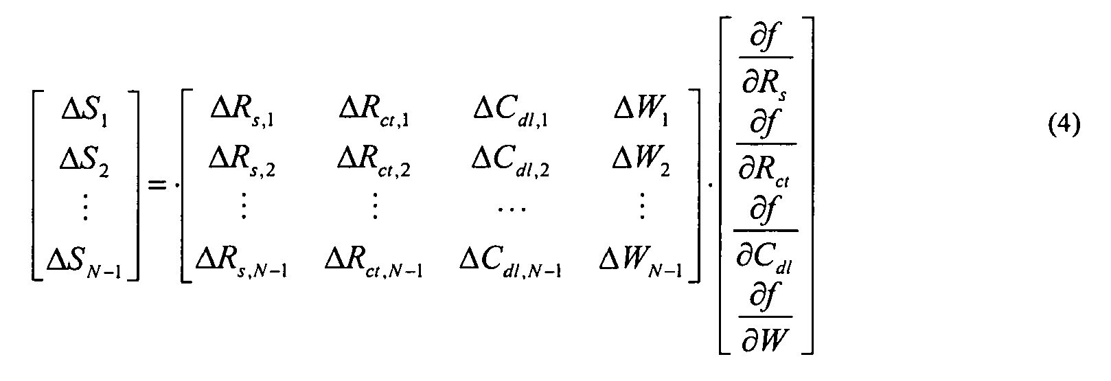
where
- Finally, the vector, [∂f/∂Rs ∂f/∂Rct ∂f/∂Cdl ∂f/∂W] T in Eq. 4 can be estimated using linear regression as shown in Eq. 6:

where
- After the estimation of the vector, [∂f/∂Rs ∂f/∂Rct ∂f/∂Cdl ∂f/∂W] T , the contribution to ΔSi from the each of the parameters Rs, Rct , Cdl and W may be subsequently computed as shown in Eq. 8:

- Eq. 8 may be re-written as shown in Eq. 9 to compute the contributions from different parameters in percentage:

- Only the parameters associated with a significant contribution to the sensitivity of
sensor 101 above a predetermined threshold may be used to construct the age compensation model. In some embodiments, a combinational contribution of 90% may be used as a criterion to select one or more principal parameters. - After the principal parameters are identified in
block 202 ofFIG. 2 byprincipal parameter identifier 104, an age compensation model may be constructed inblock 203 byage compensation modeler 105. A model equation with unknown parameters is used for the construction of a nonlinear age compensation model. The equation may be based on available sensor data as well as the observations of the sensor response. The model equation may be represented as shown in Eq. 10:
where S is the sensor sensitivity, x is the vector for the principal parameters and θ is the vector for model parameters. - If there are n observations available for the sensor, e.g., Si and xi are available, the model parameter vector, θ, can be determined by solving the optimization problem shown in Eq. 11:

where S̅=[S 1 S 2 ··· Sn ] T and G(x,θ)=[g(x 1,θ) g(x 2,θ) ··· g(x n,θ)] T . ∥·∥ represents a form of vector norm. - If only one principal parameter was identified in
block 202 ofFIG. 2 , a one-dimensional (1-D) age compensation model is determined byage compensation modeler 105. The 1-D model determines the sensitivity of thesensor 101 based on one principal parameter derived from the impedance spectrum, and is shown in Eq. 12:
where S is the sensor sensitivity, x is the cell parameter derived from the cell impedance (Rs, Rct, Cdl or W) that is identified as the principal component using the procedure inblock 202. The parameters of the age compensation model, a and b, are determined based on the test data gathered from thesensor 101. Linear regression may be used to estimate the parameters, θ=[a b] T as shown in Eq. 13:
where
- In Eq. 14, x 1,x 2, ..., xN are the measurements of the cell parameter and S1 , S2 , ..., SN are the measurements of the sensor sensitivity.
- If two principal parameters were identified in
block 202 ofFIG. 2 , a 2-D age compensation model is determined byage compensation modeler 105. The 2-D age compensation model determines the sensitivity of the gas sensor based on two principal parameters derived from the impedance spectrum, and is shown in Eq. 15:
where S is the sensor sensitivity, x1 , and x2 are the two cell parameters derived from the cell impedance (Rs , Rct , Cdl or W) that are identified as the principal components using the procedure described inblock 202. The parameters of the 2-D age compensation model, a, b and c, are determined based on the test data gathered from thesensor 101. Linear regression may be used to estimate the parameters, χ=[a b c] T as shown in Eq. 16:
where
- In Eq. 17, x1,1 , x1,2 , ..., x1,N are the N available measurements of the cell parameter x 1; x2,1 , x2,2 , ..., x2,N are the N available measurements of the cell parameter x2 ; and S1 , S2 , ..., SN are the N available measurements of the sensor sensitivity.
- If more than two principal parameters were identified in
block 202 ofFIG. 2 , a higher-order age compensation model may be constructed byage compensation modeler 105 by following the methodology described above. The resulting age compensation model determines the sensitivity of thesensor 101 based on k cell parameters derived from the impedance spectrum, and is shown in Eq. 18:
where S is the sensor sensitivity, x1 , x2, ..., and xk are the k cell parameters identified as the principal components using the procedure described inblock 202. The parameters of the high-order age compensation model, η=[a1 a2 ... ak ] T are determined based on the test data gathered from thesensor 101 and using linear regression as shown in Eq. 19:
where
- In Eq. 20, xi,1 , xi,2 , ..., x i,N (i=1, 2, ..., k) are the N available measurements of the cell parameter xi ; and S1 , S2 , ..., SN are the N available measurements of the sensor sensitivity. Note that for k=1 or k=2, Eq. 18 is equivalent to Eq. 12 or Eq. 15, respectively.
- Once an age compensation model is constructed by
age compensation modeler 105 inblock 203 ofFIG. 2 , the determined age compensation model is applied to the output ofsensor 101 during sensor operation inblock 204. The impedance spectrum and the values of the principal impedance parameters forsensor 101 may change assensor 101 ages. Therefore, the age compensation model may be applied tosensor 101 by remeasuring the impedance ofsensor 101 during operation bypotentiostat 102 andimpedance analyzer 103, recalculating the principal impedance parameter(s) byprincipal parameter identifier 104 based on the remeasured impedance spectrum provided byimpedance analyzer 103, and plugging the recalculated principal impedance parameter(s) fromprincipal parameter identifier 104 into the age compensation model determined by age compensation modeler inblock 203 to compute the current sensor sensitivity. A signal may be generated based on the current sensor sensitivity determined from the age compensation model, and added to the sensor output byadder 106 to obtain age compensatedsensor output 107. -
FIG. 4 illustrates an embodiment of amethod 400 for sensor failure detection.FIG. 4 is discussed with reference toFIG. 1 . Inblock 401, sensor impedance data is collected during operation of thesensor 101 bypotentiostat 102 andimpedance analyzer 103. Inblock 402, principal impedance parameters are determined byprincipal parameter identifier 104 using the impedance spectrum data fromimpedance analyzer 103. The impedance parameters are obtained in the same manner discussed above with respect to block 202 ofFIG. 2 . - In
block 403, a structural change or gross parameter change in the sensor impedance parameters are identified byfailure detection module 108. An estimation error associated with each parameter may also be obtained from the optimization-based fitting algorithm. A significant increase in the estimation error of an impedance parameter may indicate a structural change. A detected structural change may indicate an imminent sensor failure. Additionally, a significant change in the value of a parameter, i.e., a gross model parameter change, may also indicate an imminent sensor failure. A structural change in a principal parameter may be determined by comparing an estimation error associated with the parameter with a respective predetermined threshold value. A gross change in a principal parameter may be determined by comparing the parameter itself with a respective predetermined threshold value. If either the parameter or its estimation error are determined to be above their respective predetermined threshold value, inblock 404,failure detection module 108 determines that a sensor failure is imminent based on the structural change or gross parameter change detected in the sensor impedance data, and issues a warning.Method 400 and block 204 ofFIG. 2 may be performed contemporaneously during operation ofsensor 101 bysystem 100. -
FIG. 5 illustrates an example of acomputer 500 which may be utilized by exemplary embodiments of systems and methods for gas sensor age compensation and failure detection as embodied in software. Various operations discussed above may utilize the capabilities of thecomputer 500. One or more of the capabilities of thecomputer 500 may be incorporated in any element, module, application, and/or component discussed herein. - The
computer 500 includes, but is not limited to, PCs, workstations, laptops, PDAs, palm devices, servers, storages, application-specific systems, embedded devices, and the like. Generally, in terms of hardware architecture, thecomputer 500 may include one ormore processors 510,memory 520, and one or more input and/or output (I/O)devices 570 that are communicatively coupled via a local interface (not shown). The local interface can be, for example but not limited to, one or more buses or other wired or wireless connections, as is known in the art. The local interface may have additional elements, such as controllers, buffers (caches), drivers, repeaters, and receivers, to enable communications. Further, the local interface may include address, control, and/or data connections to enable appropriate communications among the aforementioned components. - The
processor 510 is a hardware device for executing software that can be stored in thememory 520. Theprocessor 510 can be virtually any custom made or commercially available processor, a central processing unit (CPU), a digital signal processor (DSP), or an auxiliary processor among several processors associated with thecomputer 500, and theprocessor 510 may be a semiconductor based microprocessor (in the form of a microchip) or a macroprocessor. - The
memory 520 can include any one or combination of volatile memory elements (e.g., random access memory (RAM), such as dynamic random access memory (DRAM), static random access memory (SRAM), etc.) and nonvolatile memory elements (e.g., ROM, erasable programmable read only memory (EPROM), flash memory, electronically erasable programmable read only memory (EEPROM), programmable read only memory (PROM), tape, compact disc read only memory (CDROM), disk, diskette, cartridge, cassette or the like, etc.). Moreover, thememory 520 may incorporate electronic, magnetic, optical, and/or other types of storage media. Note that thememory 520 can have a distributed architecture, where various components are situated remote from one another, but can be accessed by theprocessor 510. - The software in the
memory 520 may include one or more separate programs, each of which comprises an ordered listing of executable instructions for implementing logical functions. The software in thememory 520 may include a suitable operating system (O/S) 550,compiler 540,source code 530, and one ormore applications 560 in accordance with exemplary embodiments. Alternatively, thecompiler 540 andsource code 530 can reside on a separate development computer (not depicted). As illustrated, theapplication 560 comprises numerous functional components for implementing the features and operations of the exemplary embodiments. Theapplication 560 of thecomputer 500 may represent various applications, computational units, logic, functional units, processes, operations, virtual entities, and/or modules in accordance with exemplary embodiments, but theapplication 560 is not meant to be a limitation. - The
operating system 550 controls the execution of other computer programs, and provides scheduling, input-output control, file and data management, memory management, and communication control and related services. Theapplication 560 for implementing exemplary embodiments may be applicable on all commercially available operating systems, as well as custom developed operating systems. -
Application 560 may be a source program, executable program (object code), script, or any other entity comprising a set of instructions to be performed. When a source program, then the program is usually translated via a compiler (such as the compiler 540), assembler, interpreter, or the like, which may or may not be included within thememory 520, so as to operate properly in connection with the O/S 550. Furthermore, theapplication 560 can be written as an object oriented programming language, which has classes of data and methods, or a procedure or function-based programming language, which has routines, subroutines, and/or functions, for example but not limited to, C, C++, C#, Pascal, BASIC, API calls, HTML, XHTML, XML, ASP scripts, FORTRAN, COBOL, Perl, Java, ADA, .NET, and the like. - The I/
O devices 570 may include input devices such as, for example but not limited to, a mouse, keyboard, scanner, microphone, camera, etc. Furthermore, the I/O devices 570 may also include output devices, for example but not limited to a printer, display, etc. Finally, the I/O devices 570 may further include devices that communicate both inputs and outputs, for instance but not limited to, a NIC or modulator/demodulator (for accessing remote devices, other files, devices, systems, or a network), a radio frequency (RF) or other transceiver, a telephonic interface, a bridge, a router, etc. The I/O devices 570 can also include components for communicating over various networks, such as the Internet or intranet. - When the
computer 500 is in operation, theprocessor 510 is configured to execute software stored within thememory 520, to communicate data to and from thememory 520, and to generally control operations of thecomputer 500 pursuant to the software. Theapplication 560 and the O/S 550 are read, in whole or in part, by theprocessor 510, perhaps buffered within theprocessor 510, and then executed. - When the
application 560 is implemented in software it should be noted that theapplication 560 can be stored on virtually any computer readable medium for use by or in connection with any computer related system or method. - The
application 560 can be embodied in any computer-readable medium for use by or in connection with an instruction execution system, apparatus, or device, such as a computer-based system, processor-containing system, or other system that can fetch the instructions from the instruction execution system, apparatus, or device and execute the instructions. A "computer-readable medium" can be any means that can store, communicate, propagate, or transport the program for use by or in connection with the instruction execution system, apparatus, or device, such asmemory 520 or a medium interfacing with I/O devices 570. The computer readable medium can be, for example but not limited to, an electronic, magnetic, optical, electromagnetic, infrared, or semiconductor system, apparatus, device, or propagation medium. - More specific examples (a nonexhaustive list) of the computer-readable medium may include the following: an electrical connection (electronic) having one or more wires, a portable computer diskette (magnetic or optical), a random access memory (RAM) (electronic), a read-only memory (ROM) (electronic), an erasable programmable read-only memory (EPROM, EEPROM, or Flash memory) (electronic), an optical fiber (optical), and a portable compact disc memory (CDROM, CD R/W) (optical). Note that the computer-readable medium could even be paper or another suitable medium, upon which the program is printed or punched, as the program can be electronically captured, via for instance optical scanning of the paper or other medium, then compiled, interpreted or otherwise processed in a suitable manner if necessary, and then stored in a computer memory.
- In exemplary embodiments, where the
application 560 is implemented in hardware, theapplication 560 can be implemented with any one or a combination of the following technologies, which are well known in the art: a discrete logic circuit(s) having logic gates for implementing logic functions upon data signals, an application specific integrated circuit (ASIC) having appropriate combinational logic gates, a programmable gate array(s) (PGA), a field programmable gate array (FPGA), etc. - The technical effects and benefits of exemplary embodiments include reduction of errors in the output of a electrochemical gas sensor due to aging, and early detection of possible gas sensor failure.
- The terminology used herein is for the purpose of describing particular embodiments only and is not intended to be limiting of the invention. While the description of the present invention has been presented for purposes of illustration and description, it is not intended to be exhaustive or limited to the invention in the form disclosed. Many modifications, variations, alterations, substitutions, or equivalent arrangement not hereto described will be apparent to those of ordinary skill in the art without departing from the scope of the invention. Additionally, while various embodiments of the invention have been described, it is to be understood that aspects of the invention may include only some of the described embodiments. Accordingly, the invention is not to be seen as limited by the foregoing description, but is only limited by the scope of the appended claims.
Claims (15)
- A method for age compensation for a gas sensor (101), the method comprising:determining an impedance spectrum for the gas sensor (101) by an impedance analyzer (103);determining a set of principal parameters based on the impedance spectrum by a principal parameter identifier (104);constructing an age compensation model for the gas sensor (101) using the set of principal parameters by an age compensation modeler (105); andapplying the age compensation model to an output of the gas sensor (101).
- The method of claim 1, wherein the impedance spectrum for the gas sensor (101) is determined using a potentiostat (102).
- The method of claim 1 or 2, wherein determining the set of principal parameters comprises modeling an impedance of the gas sensor (101) using a Randles equivalent circuit (300).
- The method of claim 1, 2 or 3, wherein the set of principal parameters comprise parameters that contribute to the sensitivity of the gas sensor (101) at an amount above a predetermined threshold.
- The method of claim 1, 2, 3 or 4, wherein a sensitivity of the gas sensor (101) is a function of the electrolyte solution resistance (Rs ), the double-layer capacitance (Cdl ), the charge transfer resistance (Rct ) and the Warburg impedance (W), and wherein the set of principal parameters comprises one or more of an electrolyte solution resistance (Rs ), a double-layer capacitance (Cdl ), a charge transfer resistance (Rct ) and a Warburg impedance (W).
- The method of any preceding claim, wherein the age compensation model is determined by the age compensation modeler (105) as a function of a plurality of principal parameters in the set of principal parameters.
- The method of any preceding claim, wherein applying the age compensation model to an output of the gas sensor (101) comprises:determining an output of the age compensation model using the set of principal parameters by the age compensation modeler (105);generating a signal based on the output of the age compensation model by the age compensation modeler (105); andadding the signal to an output of the gas sensor (101) by an adder (106).
- The method of any preceding claim, further comprising detecting an imminent failure of the gas sensor (101), comprising:detecting a change in one or more of the set of principal parameters by a failure detection module (108); andissuing a failure warning based on the detected change.
- The method of claim 8, wherein detecting a change in one or more of the set of principal parameters comprises detecting a structural change in one or more of the set of principal parameters, and wherein detecting the structural change comprises determining whether an estimation error of one or more of the set of principal parameters is higher than a predetermined threshold; or wherein detecting a change in one or more of the set of principal parameters comprises detecting a gross change in one or more of the set of principal parameters, and wherein detecting the gross change comprises determining whether the one or more of the set of principal parameters is higher than a predetermined threshold.
- A system (100) for age compensation for a gas sensor (101), comprising:an impedance analyzer (103) configured to determine an impedance spectrum for the gas sensor (101);a principal parameter identifier (104) configured to determine a set of principal parameters based on the impedance spectrum; andan age compensation modeler (105) configured to construct an age compensation model for the gas sensor (101) using the set of principal parameters, and to apply the age compensation model to an output of the gas sensor (101).
- The system (100) of claim 10, wherein the set of principal parameters comprises parameters that contribute to the sensitivity of the gas sensor (101) at an amount above a predetermined threshold.
- The system (100) of claim 10 or 11, wherein a sensitivity of the gas sensor is a function of the electrolyte solution resistance (Rs ), the double-layer capacitance (Cdl ), the charge transfer resistance (Rct ) and the Warburg impedance (W), and wherein the set of principal parameters comprises one or more of an electrolyte solution resistance (Rs ), a double-layer capacitance (Cdl ), a charge transfer resistance (Rct ) and a Warburg impedance (W)
- The system (100) of claim 10, 11 or 12, further comprising an adder (106) configured to add a signal from the age compensation modeler (105) to an output of the gas sensor (101);
wherein the age compensation modeler (105) is further configured to determine an output of the age compensation model using the set of principal parameters, and to generate the signal based on the output of the age compensation model. - The system (100) of claim 10, 11, 12 or 13, further comprising a failure detection module (108) configured to detect a change in one or more of the set of principal parameters and issue a failure warning for the gas sensor (101) based on the detected change.
- A computer program product comprising a computer readable storage medium containing computer code that, when executed by a computer, implements a method as claimed in any of claims 1 to 9 for age compensation and optionally failure detection for a gas sensor (101).
Applications Claiming Priority (1)
| Application Number | Priority Date | Filing Date | Title |
|---|---|---|---|
| US12/706,097 US20110199094A1 (en) | 2010-02-16 | 2010-02-16 | Gas Sensor Age Compensation and Failure Detection |
Publications (1)
| Publication Number | Publication Date |
|---|---|
| EP2365322A1 true EP2365322A1 (en) | 2011-09-14 |
Family
ID=44064806
Family Applications (1)
| Application Number | Title | Priority Date | Filing Date |
|---|---|---|---|
| EP11250176A Withdrawn EP2365322A1 (en) | 2010-02-16 | 2011-02-15 | Gas sensor age compensation and failure detection |
Country Status (3)
| Country | Link |
|---|---|
| US (1) | US20110199094A1 (en) |
| EP (1) | EP2365322A1 (en) |
| CN (1) | CN102162826A (en) |
Cited By (1)
| Publication number | Priority date | Publication date | Assignee | Title |
|---|---|---|---|---|
| EP3635701A1 (en) * | 2017-06-08 | 2020-04-15 | Tyco Fire & Security GmbH | Prediction of false alarms in sensor-based security systems |
Families Citing this family (11)
| Publication number | Priority date | Publication date | Assignee | Title |
|---|---|---|---|---|
| JP2016008906A (en) * | 2014-06-25 | 2016-01-18 | 株式会社東芝 | Aging apparatus for constant potential electrolytic gas sensor and aging method for constant potential electrolytic gas sensor |
| KR20160007134A (en) | 2014-07-11 | 2016-01-20 | 엘지이노텍 주식회사 | Gas detection device |
| US9885685B2 (en) * | 2014-10-10 | 2018-02-06 | Ford Global Technologies, Llc | Compensating oxygen sensor aging |
| US10101194B2 (en) * | 2015-12-31 | 2018-10-16 | General Electric Company | System and method for identifying and recovering from a temporary sensor failure |
| US11079363B2 (en) | 2017-08-03 | 2021-08-03 | Industrial Scientific Corporation | Systems and methods for evaluating toxic gas sensors using electrochemical impedance spectroscopy |
| FR3076961B1 (en) * | 2018-01-16 | 2019-11-29 | Schneider Electric Industries Sas | METHOD FOR DETECTING AN ELECTRIC DYSFUNCTION, DEVICE FOR IMPLEMENTING SUCH A METHOD AND ELECTRICAL ENCLOSURE EQUIPPED WITH SUCH A DEVICE |
| CN112596490B (en) * | 2020-02-28 | 2021-09-07 | 中国电子产品可靠性与环境试验研究所((工业和信息化部电子第五研究所)(中国赛宝实验室)) | Industrial robot fault detection method, device, computer equipment and storage medium |
| CN113259427B (en) * | 2021-05-08 | 2022-05-03 | 德微电技术(深圳)有限公司 | System fault rapid troubleshooting method and device and computer equipment |
| WO2024005837A1 (en) * | 2022-07-01 | 2024-01-04 | Brewer Science, Inc. | Differential current limiting for voltammetry sensor lifetime extension |
| CN116242412B (en) * | 2023-02-22 | 2025-11-18 | 中国农业大学 | Sensor fault diagnosis methods, devices, electronic equipment and storage media |
| CN116046049B (en) * | 2023-03-07 | 2023-07-21 | 深圳市兆兴博拓科技股份有限公司 | Self-calibration sensor and calibration method and system |
Citations (3)
| Publication number | Priority date | Publication date | Assignee | Title |
|---|---|---|---|---|
| WO2000014523A2 (en) * | 1998-09-09 | 2000-03-16 | Cominco Ltd. | Apparatus for monitoring the operability of an electrochemical sensor |
| DE102005032134A1 (en) * | 2005-07-07 | 2007-01-18 | Endress + Hauser Wetzer Gmbh + Co Kg | Measuring device for determining and / or monitoring a process variable and method for monitoring the measuring device |
| US20080000779A1 (en) * | 2005-12-30 | 2008-01-03 | Medtronic Minimed, Inc. | Method and System for Remedying Sensor Malfunctions Detected by Electrochemical Impedance Spectroscopy |
Family Cites Families (57)
| Publication number | Priority date | Publication date | Assignee | Title |
|---|---|---|---|---|
| US3661748A (en) * | 1970-04-07 | 1972-05-09 | Instrumentation Labor Inc | Fault sensing instrumentation |
| US4189367A (en) * | 1978-10-19 | 1980-02-19 | Leeds & Northrup Company | Method for testing ion selective electrodes in continuous measuring systems |
| DE3033796A1 (en) * | 1980-09-09 | 1982-04-22 | Bayer Ag, 5090 Leverkusen | ELECTROCHEMICAL SENSOR FOR DETECTING REDUCING GASES, ESPECIALLY CARBON MONOXIDE, HYDRAZINE AND HYDROGEN IN AIR |
| US4337745A (en) * | 1980-09-26 | 1982-07-06 | General Motors Corporation | Closed loop air/fuel ratio control system with oxygen sensor signal compensation |
| US4468608A (en) * | 1981-12-11 | 1984-08-28 | Instrumentation Laboratory Inc. | Electrochemical sensor instrumentation |
| DE3640242A1 (en) * | 1986-11-25 | 1988-05-26 | Vdo Schindling | CIRCUIT ARRANGEMENT FOR A SENSOR |
| US4750353A (en) * | 1987-02-25 | 1988-06-14 | Allied Corporation | Method of voltage compensation for an air/fuel ratio sensor |
| JPH02118443A (en) * | 1988-10-28 | 1990-05-02 | Shinei Kk | Acidic gas detecting element |
| GB8907564D0 (en) * | 1989-04-04 | 1989-05-17 | Neotronics Technology Plc | Fault detection in electrochemical gas sensing equipment |
| US5060514A (en) * | 1989-11-30 | 1991-10-29 | Puritan-Bennett Corporate | Ultrasonic gas measuring device |
| US5273640A (en) * | 1990-06-11 | 1993-12-28 | Matsushita Electric Works, Ltd. | Electrochemical gas sensor |
| JPH0464863A (en) * | 1990-07-04 | 1992-02-28 | Mitsubishi Electric Corp | Electric hot water heater |
| US6198275B1 (en) * | 1995-06-07 | 2001-03-06 | American Electronic Components | Electronic circuit for automatic DC offset compensation for a linear displacement sensor |
| DE4445947C2 (en) * | 1994-12-22 | 1998-03-12 | Draegerwerk Ag | Process for the detection of sources of error in amperometric measuring cells |
| DE19510574C1 (en) * | 1995-03-23 | 1996-06-05 | Testo Gmbh & Co | Condition monitoring system for amperometric electrochemical gas sensor |
| CA2266485C (en) * | 1997-07-14 | 2009-01-27 | Matsushita Electric Industrial Co., Ltd. | Automatic compensation sensor |
| US6382015B1 (en) * | 1998-06-11 | 2002-05-07 | Toyota Jidosha Kabushiki Kaisha | Air-fuel ratio sensor resistance detecting apparatus |
| JP2001116719A (en) * | 1999-10-19 | 2001-04-27 | Shimadzu Corp | Electrochemical gas sensor |
| US6703827B1 (en) * | 2000-06-22 | 2004-03-09 | American Electronics Components, Inc. | Electronic circuit for automatic DC offset compensation for a linear displacement sensor |
| US6428684B1 (en) * | 2000-08-02 | 2002-08-06 | Industrial Scientific Corporation | Method and apparatus for diagnosing the condition of a gas sensor |
| US7141859B2 (en) * | 2001-03-29 | 2006-11-28 | Georgia Tech Research Corporation | Porous gas sensors and method of preparation thereof |
| WO2003052387A2 (en) * | 2001-12-14 | 2003-06-26 | Rosemount Analytical Inc. | A pH SENSOR WITH INTERNAL SOLUTION GROUND |
| CA2523385C (en) * | 2002-04-05 | 2014-04-01 | Thermal Technologies, Inc. | System for quantifying blood flow in tissue with periodic updating of tissue baseline conditions |
| DE10217762C1 (en) * | 2002-04-20 | 2003-04-10 | Draeger Medical Ag | Respiration gas supply control method for artificial respirator compares actual respiration path pressure with intial respiration path pressure for regulation of respiration gas supply parameter |
| DE10225880A1 (en) * | 2002-06-11 | 2003-12-24 | Patent Treuhand Ges Fuer Elektrische Gluehlampen Mbh | Discharge lamp operating circuit with a current control circuit and a circuit for detecting proximity to a capacitive operation |
| JP3753122B2 (en) * | 2002-11-13 | 2006-03-08 | トヨタ自動車株式会社 | Abnormality judgment device |
| GB0317513D0 (en) * | 2003-07-25 | 2003-08-27 | Megger Ltd | A method and apparatus for determining the complex impedance of an electrical component |
| US7206714B2 (en) * | 2003-09-01 | 2007-04-17 | Toyota Jidosha Kabushiki Kaisha | Exhaust gas sensor control device |
| US7142105B2 (en) * | 2004-02-11 | 2006-11-28 | Southwest Sciences Incorporated | Fire alarm algorithm using smoke and gas sensors |
| US7307486B2 (en) * | 2004-03-22 | 2007-12-11 | Mobius Microsystems, Inc. | Low-latency start-up for a monolithic clock generator and timing/frequency reference |
| US7413645B2 (en) * | 2004-05-05 | 2008-08-19 | Mine Safety Appliances Company | Devices, systems and methods for testing gas sensors and correcting gas sensor output |
| DE102005033263A1 (en) * | 2004-07-16 | 2006-02-23 | Denso Corp., Kariya | Gas concentration meter |
| US7232512B2 (en) * | 2004-08-25 | 2007-06-19 | Honeywell International, Inc. | System and method of sensitivity adjustment for an electrochemical sensor |
| US7297242B2 (en) * | 2004-08-25 | 2007-11-20 | Honeywell International, Inc. | Self-adjusting electrochemical sensor |
| JP4424182B2 (en) * | 2004-12-06 | 2010-03-03 | 株式会社デンソー | Exhaust temperature estimation device for internal combustion engine |
| SE0403229D0 (en) * | 2004-12-30 | 2004-12-30 | Abb Ab | A method and a system for adaptive compensation of the temperature operation of a sensor |
| JP4645984B2 (en) * | 2005-07-05 | 2011-03-09 | 株式会社デンソー | Deterioration detection device for exhaust gas sensor |
| US7774038B2 (en) * | 2005-12-30 | 2010-08-10 | Medtronic Minimed, Inc. | Real-time self-calibrating sensor system and method |
| US20070173712A1 (en) * | 2005-12-30 | 2007-07-26 | Medtronic Minimed, Inc. | Method of and system for stabilization of sensors |
| US7985330B2 (en) * | 2005-12-30 | 2011-07-26 | Medtronic Minimed, Inc. | Method and system for detecting age, hydration, and functional states of sensors using electrochemical impedance spectroscopy |
| JP2009524019A (en) * | 2006-01-12 | 2009-06-25 | ティムケン ユーエス コーポレーション | Magnetic sensor with compensation |
| WO2007089804A2 (en) * | 2006-01-31 | 2007-08-09 | University Of Virginia Patent Foundation | Method and system for operating in-situ (sampling) chemical sensors |
| JP4198718B2 (en) * | 2006-04-03 | 2008-12-17 | 本田技研工業株式会社 | Air-fuel ratio control device for internal combustion engine |
| US20070299617A1 (en) * | 2006-06-27 | 2007-12-27 | Willis John P | Biofouling self-compensating biosensor |
| WO2008071647A1 (en) * | 2006-12-12 | 2008-06-19 | OCé PRINTING SYSTEMS GMBH | Method for controlling a development process in different operating phases |
| US7751864B2 (en) * | 2007-03-01 | 2010-07-06 | Roche Diagnostics Operations, Inc. | System and method for operating an electrochemical analyte sensor |
| JP4462282B2 (en) * | 2007-03-14 | 2010-05-12 | トヨタ自動車株式会社 | Exhaust control device for internal combustion engine |
| CN101038284B (en) * | 2007-04-25 | 2011-04-27 | 博奥生物有限公司 | Method for enhancing electric impedance detecting sensibility of electric impedance detecting device |
| US7523653B2 (en) * | 2007-06-14 | 2009-04-28 | Ford Gobal Technologies, Llc | Exhaust temperature sensor monitoring |
| US20090007636A1 (en) * | 2007-07-02 | 2009-01-08 | Therm-O-Disc, Incorporated | Chemiresistor Sensor System Compensated for Temperature and Aging Effects |
| JP4760806B2 (en) * | 2007-09-04 | 2011-08-31 | 株式会社デンソー | Gas sensor degradation simulator |
| EP2239562B1 (en) * | 2009-04-06 | 2013-11-13 | Life Safety Distribution AG | Checking electrochemical gas sensors |
| WO2010135435A2 (en) * | 2009-05-19 | 2010-11-25 | Drexel University | Detection and measurement of mass change using an electromechanical resonator |
| US8365574B2 (en) * | 2009-12-07 | 2013-02-05 | Hamilton Sundstrand Corporation | Systems and methods for minimizing stray current in capacitive sensor data |
| US8549363B2 (en) * | 2010-01-08 | 2013-10-01 | International Business Machines Corporation | Reliability and performance of a system-on-a-chip by predictive wear-out based activation of functional components |
| US20110309918A1 (en) * | 2010-06-17 | 2011-12-22 | Immersion Corporation | System and Method for Compensating for Aging Haptic Actuators |
| US8680523B2 (en) * | 2010-12-16 | 2014-03-25 | IP Cube Partners (ICP) Co., Ltd. | Sensor for semiconductor degradation monitoring and modeling |
-
2010
- 2010-02-16 US US12/706,097 patent/US20110199094A1/en not_active Abandoned
-
2011
- 2011-02-15 EP EP11250176A patent/EP2365322A1/en not_active Withdrawn
- 2011-02-15 CN CN2011100669500A patent/CN102162826A/en active Pending
Patent Citations (3)
| Publication number | Priority date | Publication date | Assignee | Title |
|---|---|---|---|---|
| WO2000014523A2 (en) * | 1998-09-09 | 2000-03-16 | Cominco Ltd. | Apparatus for monitoring the operability of an electrochemical sensor |
| DE102005032134A1 (en) * | 2005-07-07 | 2007-01-18 | Endress + Hauser Wetzer Gmbh + Co Kg | Measuring device for determining and / or monitoring a process variable and method for monitoring the measuring device |
| US20080000779A1 (en) * | 2005-12-30 | 2008-01-03 | Medtronic Minimed, Inc. | Method and System for Remedying Sensor Malfunctions Detected by Electrochemical Impedance Spectroscopy |
Non-Patent Citations (2)
| Title |
|---|
| FERNANDEZ-SANCHEZ C ET AL: "Electrochemical impedance spectroscopy studies of polymer degradation: application to biosensor development", TRAC, TRENDS IN ANALYTICAL CHEMISTRY, ELSEVIER, AMSTERDAM, NL, vol. 24, no. 1, 1 January 2005 (2005-01-01), pages 37 - 48, XP004706415, ISSN: 0165-9936, DOI: 10.1016/J.TRAC.2004.08.010 * |
| KITZELMANN D ET AL: "ELECTROCHEMISCHE GASSENSOREN - WIRKUNGSWEISEN UND MOEGLICHKEITEN ZUR FUNKTIONSUEBERWACHUNG. ELECTROCHEMICAL GAS SENSORS- PRINCIPLES AND PERSPECTIVES OF A CONTINUOUS SENSOR CHECK", TECHNISCHES MESSEN TM, R.OLDENBOURG VERLAG. MUNCHEN, DE, vol. 62, no. 4, 1 April 1995 (1995-04-01), pages 152 - 159, XP000516378, ISSN: 0171-8096 * |
Cited By (1)
| Publication number | Priority date | Publication date | Assignee | Title |
|---|---|---|---|---|
| EP3635701A1 (en) * | 2017-06-08 | 2020-04-15 | Tyco Fire & Security GmbH | Prediction of false alarms in sensor-based security systems |
Also Published As
| Publication number | Publication date |
|---|---|
| US20110199094A1 (en) | 2011-08-18 |
| CN102162826A (en) | 2011-08-24 |
Similar Documents
| Publication | Publication Date | Title |
|---|---|---|
| US20110199094A1 (en) | Gas Sensor Age Compensation and Failure Detection | |
| EP3662275B1 (en) | Systems and methods for evaluating toxic gas sensors using electrochemical impedance spectroscopy | |
| Goldammer et al. | Determination of the distribution of relaxation times by means of pulse evaluation for offline and online diagnosis of lithium-ion batteries | |
| US10139291B2 (en) | Sensor calibration method and apparatus | |
| CN101153858A (en) | Method for detecting erroneous measurements obtained with ion-selective electrodes | |
| CN119469549B (en) | Diagnostic method for pressure sensor performance detection | |
| López C et al. | A computational framework for identifiability and ill-conditioning analysis of lithium-ion battery models | |
| Wenzel et al. | Online drift compensation for chemical sensors using estimation theory | |
| Khatri et al. | Drift compensation of commercial water quality sensors using machine learning to extend the calibration lifetime | |
| Thöns et al. | On damage detection system information for structural systems | |
| CN115062273A (en) | Photoelectric sensor precision control method and system for industrial internet | |
| Liu et al. | Misspecification analysis of two‐phase gamma‐Wiener degradation models | |
| US11143644B2 (en) | System and method for determining a contamination level in an emissions measurement device or system | |
| JP6462145B2 (en) | Detecting temporary errors in body fluid samples | |
| KR20240138482A (en) | Method and Apparatus for Determining Concentration of Selected Component in Detected Gas | |
| CN114877926B (en) | Sensor fault detection and diagnosis method, medium, electronic equipment and system | |
| US20220058075A1 (en) | Identifying faults in system data | |
| CN116338094B (en) | A gas concentration calibration method and apparatus for carbon emission gas detection | |
| KR101514883B1 (en) | Aparatus, method and system for diagnosing decrepit of pipe | |
| HK1161645A (en) | Gas sensor age compensation and failure detection | |
| Madrolle et al. | Dual-temperature mode for quantitative analysis of gas mixtures with MOX sensor | |
| Baffi et al. | Prediction intervals for non-linear projection to latent structures regression models | |
| CN116735667A (en) | Apparatus and method for determining target gas concentration in mobile applications | |
| EP4080202A1 (en) | Gas sensing device and method for determining a calibrated measurement value of a concentration of a target gas | |
| CN119943397B (en) | A method and related equipment for temperature detection and compensation in blood glucose meters |
Legal Events
| Date | Code | Title | Description |
|---|---|---|---|
| PUAI | Public reference made under article 153(3) epc to a published international application that has entered the european phase |
Free format text: ORIGINAL CODE: 0009012 |
|
| AK | Designated contracting states |
Kind code of ref document: A1 Designated state(s): AL AT BE BG CH CY CZ DE DK EE ES FI FR GB GR HR HU IE IS IT LI LT LU LV MC MK MT NL NO PL PT RO RS SE SI SK SM TR |
|
| AX | Request for extension of the european patent |
Extension state: BA ME |
|
| 17P | Request for examination filed |
Effective date: 20120314 |
|
| STAA | Information on the status of an ep patent application or granted ep patent |
Free format text: STATUS: THE APPLICATION HAS BEEN WITHDRAWN |
|
| 18W | Application withdrawn |
Effective date: 20140113 |