EP2365225A2 - Fan assembly - Google Patents
Fan assembly Download PDFInfo
- Publication number
- EP2365225A2 EP2365225A2 EP11157166A EP11157166A EP2365225A2 EP 2365225 A2 EP2365225 A2 EP 2365225A2 EP 11157166 A EP11157166 A EP 11157166A EP 11157166 A EP11157166 A EP 11157166A EP 2365225 A2 EP2365225 A2 EP 2365225A2
- Authority
- EP
- European Patent Office
- Prior art keywords
- fan assembly
- disposed
- fan
- load
- blades
- Prior art date
- Legal status (The legal status is an assumption and is not a legal conclusion. Google has not performed a legal analysis and makes no representation as to the accuracy of the status listed.)
- Granted
Links
- 230000003068 static effect Effects 0.000 claims description 5
- 238000010586 diagram Methods 0.000 description 13
- 230000000694 effects Effects 0.000 description 2
- 230000004048 modification Effects 0.000 description 2
- 238000012986 modification Methods 0.000 description 2
- 230000005540 biological transmission Effects 0.000 description 1
- 238000006243 chemical reaction Methods 0.000 description 1
- 239000012141 concentrate Substances 0.000 description 1
- 230000003247 decreasing effect Effects 0.000 description 1
- 230000017525 heat dissipation Effects 0.000 description 1
- 230000003993 interaction Effects 0.000 description 1
- 238000004519 manufacturing process Methods 0.000 description 1
- 238000004064 recycling Methods 0.000 description 1
Images




Classifications
-
- F—MECHANICAL ENGINEERING; LIGHTING; HEATING; WEAPONS; BLASTING
- F04—POSITIVE - DISPLACEMENT MACHINES FOR LIQUIDS; PUMPS FOR LIQUIDS OR ELASTIC FLUIDS
- F04D—NON-POSITIVE-DISPLACEMENT PUMPS
- F04D25/00—Pumping installations or systems
- F04D25/02—Units comprising pumps and their driving means
- F04D25/04—Units comprising pumps and their driving means the pump being fluid-driven
-
- F—MECHANICAL ENGINEERING; LIGHTING; HEATING; WEAPONS; BLASTING
- F03—MACHINES OR ENGINES FOR LIQUIDS; WIND, SPRING, OR WEIGHT MOTORS; PRODUCING MECHANICAL POWER OR A REACTIVE PROPULSIVE THRUST, NOT OTHERWISE PROVIDED FOR
- F03D—WIND MOTORS
- F03D1/00—Wind motors with rotation axis substantially parallel to the air flow entering the rotor
- F03D1/02—Wind motors with rotation axis substantially parallel to the air flow entering the rotor having a plurality of rotors
- F03D1/025—Wind motors with rotation axis substantially parallel to the air flow entering the rotor having a plurality of rotors coaxially arranged
-
- F—MECHANICAL ENGINEERING; LIGHTING; HEATING; WEAPONS; BLASTING
- F03—MACHINES OR ENGINES FOR LIQUIDS; WIND, SPRING, OR WEIGHT MOTORS; PRODUCING MECHANICAL POWER OR A REACTIVE PROPULSIVE THRUST, NOT OTHERWISE PROVIDED FOR
- F03D—WIND MOTORS
- F03D1/00—Wind motors with rotation axis substantially parallel to the air flow entering the rotor
- F03D1/04—Wind motors with rotation axis substantially parallel to the air flow entering the rotor having stationary wind-guiding means, e.g. with shrouds or channels
-
- F—MECHANICAL ENGINEERING; LIGHTING; HEATING; WEAPONS; BLASTING
- F03—MACHINES OR ENGINES FOR LIQUIDS; WIND, SPRING, OR WEIGHT MOTORS; PRODUCING MECHANICAL POWER OR A REACTIVE PROPULSIVE THRUST, NOT OTHERWISE PROVIDED FOR
- F03D—WIND MOTORS
- F03D9/00—Adaptations of wind motors for special use; Combinations of wind motors with apparatus driven thereby; Wind motors specially adapted for installation in particular locations
- F03D9/20—Wind motors characterised by the driven apparatus
- F03D9/25—Wind motors characterised by the driven apparatus the apparatus being an electrical generator
-
- F—MECHANICAL ENGINEERING; LIGHTING; HEATING; WEAPONS; BLASTING
- F04—POSITIVE - DISPLACEMENT MACHINES FOR LIQUIDS; PUMPS FOR LIQUIDS OR ELASTIC FLUIDS
- F04D—NON-POSITIVE-DISPLACEMENT PUMPS
- F04D19/00—Axial-flow pumps
- F04D19/007—Axial-flow pumps multistage fans
-
- F—MECHANICAL ENGINEERING; LIGHTING; HEATING; WEAPONS; BLASTING
- F04—POSITIVE - DISPLACEMENT MACHINES FOR LIQUIDS; PUMPS FOR LIQUIDS OR ELASTIC FLUIDS
- F04D—NON-POSITIVE-DISPLACEMENT PUMPS
- F04D19/00—Axial-flow pumps
- F04D19/02—Multi-stage pumps
-
- F—MECHANICAL ENGINEERING; LIGHTING; HEATING; WEAPONS; BLASTING
- F04—POSITIVE - DISPLACEMENT MACHINES FOR LIQUIDS; PUMPS FOR LIQUIDS OR ELASTIC FLUIDS
- F04D—NON-POSITIVE-DISPLACEMENT PUMPS
- F04D25/00—Pumping installations or systems
- F04D25/02—Units comprising pumps and their driving means
- F04D25/06—Units comprising pumps and their driving means the pump being electrically driven
- F04D25/0606—Units comprising pumps and their driving means the pump being electrically driven the electric motor being specially adapted for integration in the pump
- F04D25/0613—Units comprising pumps and their driving means the pump being electrically driven the electric motor being specially adapted for integration in the pump the electric motor being of the inside-out type, i.e. the rotor is arranged radially outside a central stator
-
- F—MECHANICAL ENGINEERING; LIGHTING; HEATING; WEAPONS; BLASTING
- F04—POSITIVE - DISPLACEMENT MACHINES FOR LIQUIDS; PUMPS FOR LIQUIDS OR ELASTIC FLUIDS
- F04D—NON-POSITIVE-DISPLACEMENT PUMPS
- F04D25/00—Pumping installations or systems
- F04D25/02—Units comprising pumps and their driving means
- F04D25/08—Units comprising pumps and their driving means the working fluid being air, e.g. for ventilation
-
- F—MECHANICAL ENGINEERING; LIGHTING; HEATING; WEAPONS; BLASTING
- F04—POSITIVE - DISPLACEMENT MACHINES FOR LIQUIDS; PUMPS FOR LIQUIDS OR ELASTIC FLUIDS
- F04D—NON-POSITIVE-DISPLACEMENT PUMPS
- F04D25/00—Pumping installations or systems
- F04D25/16—Combinations of two or more pumps ; Producing two or more separate gas flows
- F04D25/166—Combinations of two or more pumps ; Producing two or more separate gas flows using fans
-
- F—MECHANICAL ENGINEERING; LIGHTING; HEATING; WEAPONS; BLASTING
- F05—INDEXING SCHEMES RELATING TO ENGINES OR PUMPS IN VARIOUS SUBCLASSES OF CLASSES F01-F04
- F05B—INDEXING SCHEME RELATING TO WIND, SPRING, WEIGHT, INERTIA OR LIKE MOTORS, TO MACHINES OR ENGINES FOR LIQUIDS COVERED BY SUBCLASSES F03B, F03D AND F03G
- F05B2220/00—Application
- F05B2220/60—Application making use of surplus or waste energy
- F05B2220/602—Application making use of surplus or waste energy with energy recovery turbines
-
- Y—GENERAL TAGGING OF NEW TECHNOLOGICAL DEVELOPMENTS; GENERAL TAGGING OF CROSS-SECTIONAL TECHNOLOGIES SPANNING OVER SEVERAL SECTIONS OF THE IPC; TECHNICAL SUBJECTS COVERED BY FORMER USPC CROSS-REFERENCE ART COLLECTIONS [XRACs] AND DIGESTS
- Y02—TECHNOLOGIES OR APPLICATIONS FOR MITIGATION OR ADAPTATION AGAINST CLIMATE CHANGE
- Y02E—REDUCTION OF GREENHOUSE GAS [GHG] EMISSIONS, RELATED TO ENERGY GENERATION, TRANSMISSION OR DISTRIBUTION
- Y02E10/00—Energy generation through renewable energy sources
- Y02E10/70—Wind energy
- Y02E10/72—Wind turbines with rotation axis in wind direction
Definitions
- the present invention relates to a wind energy conversion device. More particularly, the present invention relates to a fan assembly with function of dynamic pressurizing, flow guiding and wind-energy recycling.
- Fans are widely used nowadays. For example, they are used in heat-dissipation devices, hair dryers, indoor air exhausting devices and wind generators in the wind tunnel laboratory. These different examples of fans may have similar or different structures.
- Fig. 1 is a schematic diagram of a known fan.
- the fan 500 used for dissipating heat in conventional computer rooms includes a rotor 520 and a stator 530.
- the rotor 520 having a hub 521 and several blades 522, is disposed on a base 501 and is coupled to the stator 530.
- the airflow Q1 is generated by the rotation of the blades 522, thereby controlling the temperature of the computer room.
- the blades 522 with greater radial length are required.
- the length of the blades 522 needs 18-40 cm.
- the weight and the torsion of the rotor 520 will be greatly increased. Therefore, a motor with higher power and larger size is needed.
- the efficiency of the fan 500 is lowered and a higher driving current is required.
- the overall size of the fan is increased, and the airflow intake will be reduced accordingly.
- the fan 500 will occupy more space and the overall power consumption is greatly increased.
- a fan assembly is disclosed according to one object of the invention.
- the fan assembly is capable of maintaining the original flow amount and torsion and even providing an extra amount of airflow, without increasing the size and the power of the motor.
- a fan assembly including a motor with lower power and smaller size is disclosed.
- the power consumption of the motor is lowered, the efficiency of the motor is increased, and the overall volume of the fan assembly is reduced. Accordingly, the region of the fan assembly that the airflow cannot pass through is reduced, and the dead space can be reduced.
- the fan assembly includes an active fan, a supporting base and a passive element.
- the active fan includes a first impeller and a motor.
- the passive element is driven to rotate by an airflow from the active fan.
- the passive element includes a second impeller and at least one first load connected to the second impeller. Due to the reason that the passive element is driven by the airflow from the active fan, the requirements of low rotation speed and high efficiency of the motor are meet.
- the fan assembly of the present invention maintains the original airflow volume and torsion and even provides extra flow amount without increasing the size and the power of the motor.
- the motor only needs to drive the active fan to provide the airflow, so the passive element can be subsequently driven by the airflow. Therefore, a motor with lower power and smaller size can be utilized in the fan assembly, not only lowering the power consumption but also reducing the overall volume of the fan assembly. The region of the fan assembly that the airflow cannot pass through is reduced, and the dead space is reduced accordingly. Moreover, the manufacturing cost is saved and the competitiveness of the product is enhanced.
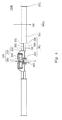
- FIG. 2 is a schematic diagram of a fan assembly according to the first embodiment of the invention.
- a fan assembly 100 including at least one active fan 200, a supporting base 400 and a passive element 300 is disclosed.
- the active fan 200 is coupled to the passive element 300 and provides an airflow to drive the passive element 300.
- the active fan 200 includes a motor 250 and a first impeller 210.
- the first impeller 210 includes a first hub 220 and a plurality of first blades 230.
- the first blades 230 are disposed around the first hub 220.
- the first impeller 210 is driven by the motor 250 with respect to a central axis C.
- the passive element 300 includes a second impeller 305 and at least one load 340.
- the second impeller 305 faces the first impeller 210 and includes a second hub 310, a plurality of second blades 320 and a first annular guiding structure 330.
- the second hub 310 is disposed on the supporting base 400.
- the second blades 320 are disposed around the second hub 310.
- the first annular guiding structure 330 is disposed at the distal ends of the second blades 320, and thus the second hub 310 is surrounded by the first annular guiding structure 330.
- the first load 340 is connected to the second impeller 350. More specifically, the first load 340 is fixed to the first annular guiding structure 330 so as to revolve simultaneously with the second blades 320.
- the airflow Q2 generated by the first impeller 210 will drive the second blades 320 to rotate with respect to the central axis C.
- the first load 340 can simultaneously rotate with the second impeller 305.
- the inner wall 331 of the first annular guiding structure 330 of this embodiment confines an accommodating space 332.
- the accommodating space 332 accommodates the second hub 310 and the second blades 320 disposed around the second hub 310. Further, at least one part of the first blade 230 or the entire first impeller 210 can also extend into the accommodating space 332.
- the inner wall 331 of the first annular guiding structure 330 guides the airflow Q2 generated by the first blades 230 toward the second blades 320, thereby driving the second impeller 305 to rotate.
- the rotation efficiency of the second blade 320 increases accordingly.
- the inner wall 331 of the first annular guiding structure 330 is in parallel with (as shown in figures) or not in parallel with the central axis C (not shown in the figures).
- the slope of the inner wall 331 of the fist annular guiding structure 330 gradually increases along the direction toward the first impeller 210 so as to expand the accommodating space 332.
- the first impeller 210 of a larger size is able to fit into the accommodating space 332, and the airflow Q2 for driving the second impeller 305 can be increased accordingly.
- Fig. 3A is a schematic diagram of a fan assembly according to the second embodiment of the invention.
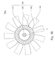
- Fig. 3B is a top view of the passive element 300a in Fig. 3A .
- the fan assembly 100a of this embodiment differs from the fan assembly 100 of the first embodiment in that the first load 340 (shown in Fig. 2 ) of the first embodiment is replaced by a plurality of third blades 341 in the second embodiment.
- the third blades 341 are equidistantly disposed at the external edge of the first annular guiding structure 330. Therefore, when the first impeller 210 rotates, the second impeller 305 and the third blades 341 rotate with respect to the central axis C simultaneously.
- the second embodiment further provides an extra airflow Q3 in addition to the airflow Q2 generated by the first impeller 210.
- the airflow Q3 is generated by the third blades 341 simultaneously rotating with the second impeller 305.
- the diameter of the first impeller 210 is smaller than that of the passive element 300a (for example 18-40 cm), and the motor 250 simply needs to drive the second impeller 305.
- the motor 250 for driving the second impeller 305 is smaller than that for driving the impeller of the fan 500 (having a diameter of 18-40 cm) as shown in Fig. 1 .
- a lower power motor i.e. a smaller size motor, can be used in the fan assembly 100a of the present invention.
- the power consumption of the motor is reduced, the efficiency of the motor is improved, and the overall volume of the fan assembly is decreased. Further, the region of the fan assembly that the airflow cannot pass through is reduced, thereby reducing the dead space.
- the fan assembly 100a of this embodiment at least maintains the original flow amount and rotation torsion, and even provides extra airflow volume (Q2+Q3).
- Fig. 4 is a schematic diagram of a fan assembly according to the third embodiment of the invention.
- the fan assembly 100b of the third embodiment differs from the fan assembly 100a of the second embodiment in that the passive element 300b further includes a second annular guiding structure 342.
- the second annular guiding structure 342 is disposed at the distal ends of the third blades 341, and thus the third blades 341 are surrounded by the second annular guiding structure 342.
- the number of the second blades 320 can be identical to that of the third blades 341.
- the second blades 320 and the third blades 341 can also be different in numbers so as to provide better operative effects.
- the numbers and the lengths of the second blades 320 and the third blades 341 can be adjustable in accordance with practical requirements.
- the radial length of each third blade 341 can be 9, 15, or even 40 cm.
- Fig. 5 is a top view of an active fan according to the fourth embodiment of the invention.
- the active fan 201 of the fourth embodiment can further include a third annular guiding structure 240.
- the third annular guiding structure 240 is connected to the distal ends of the first blades 230, and thus the first blades 230 are surrounded by the second annular guiding structure 240.
- the airflow Q2 (as shown in Fig. 3A ) generated by the first blades 230 can be gathered and guided to the accommodating space 332 by the inner wall of the third annular guiding structure 240 so as to concentrate the airflow Q2 generated by the second impeller 305.
- Fig. 6 is a top view of a passive element according to the fifth embodiment of the invention.
- the fan assembly 100b of the fifth embodiment differs from the fan assembly 100 of the first embodiment in that the first load 340 of the first embodiment (as shown in Fig. 2 ) is replaced by a plate 343.
- the plate 343 is exemplified by a circular ring connected to the external edge of the first annular guiding structure 330.
- the plate 343 can be used for conveying objects.
- Fig. 7 is a schematic diagram of a fan assembly 100c according to the sixth embodiment of the invention.
- the sixth embodiment differs from the first embodiment in that the load 340 of the first embodiment is replaced by one or more first electromagnetic components 334a, such as magnets.
- the first electromagnetic component 334a is disposed at the external edge of the first annular guiding structure 330.
- a second electromagnetic component 334b (such as a coil) is disposed at a static element near the first electromagnetic component 334a.
- the first electromagnetic component 334a when an active electromagnetic interaction takes place between the first electromagnetic component 334a and the second electromagnetic component 334b, the first electromagnetic component 334a also facilitates the rotation of the passive element 300d.
- the first electromagnetic component 334a and the second electromagnetic component 334b can also be disposed at other locations of the passive element 300d.
- another electromagnetic component 344a (the portion of the dashed lines in Fig. 7 ) is disposed on the second hub 310
- another electromagnetic component 344b corresponding to the electromagnetic component 344a (the portion of the dashed lines in Fig. 7 ) is disposed at a protruded portion 401 of the supporting base 400.
- the fan assembly 100c can also include the first electromagnetic components 334a and 344a and the second electromagnetic components 334b and 344b at the same time, depending on practical needs.
- Fig. 8 is a top view of a passive element 300e and a rotatable element W1 according to the seventh embodiment of the invention.
- the active fan is omitted in this figure to clearly show the relation between the passive element 300e and the rotatable element W1.
- the seventh embodiment differs from the first embodiment in that the fist load 340 of the first embodiment (as shown in Fig. 2 ) is replaced by one or more belts 346 (such as transmission belts) in the seventh embodiment.
- the belt 346 surrounds the external edge of the rotatable element W1 and the external edge of the first annular guiding structure 330 at the same time. In this manner, the belt 346 is driven by the second impeller 305 of the passive element 300e as the first impeller 210 (as shown in Fig. 2 ) rotates, and the rotatable element W1 is driven by the belt 346 accordingly.
- Fig. 9 is a top view of a passive element 300f and another rotatable element W2 according to the eighth embodiment of the invention.
- the active fan in this figure is omitted for the clarity of the relation between the passive element 300f and the rotatable element W2.
- the eighth embodiment differs from the first embodiment in that the first load 340 (as shown in Fig. 2 ) of the first embodiment is replaced by a gear set 345 in the eighth embodiment.
- the gear set 345 includes several gear teeth equidistantly disposed at the external edge of the first annular guiding structure 330, and the first annular guiding structure 330 is surrounded by the gear teeth. Meanwhile, the gear set 345 is engaged with another gear set 345' on the rotatable element W2. In this manner, when the first impeller 210 (as shown in Fig. 2 ) rotates, the second impeller 305 of the passive element 300f drives the gear set 345 to rotate about the central axis C. By the engagement of the two gear sets 345 and 345', the rotation of the rotatable element W2 is achieved.
- Fig. 10 is a schematic diagram of a fan assembly according to the ninth embodiment of the invention.
- the fan assembly 100d further includes a second load 350 connected to the external edge of the first load 340.
- the first load 340 of the ninth embodiment can be exemplified by the blades, the plate, the electromagnetic component, the gear set or the belt described in the above eight embodiments.
- the second load 350 of the ninth embodiment can be exemplified by the blades, the plate, the electromagnetic component, the gear set or the belt described in the above eight embodiments.
- Other reasonable variations of the second load 350 can be utilized in the invention so as to provide more practical applications on simultaneous rotating and to enhance the effect of the invention.
- the first load 340 of the ninth embodiment is exemplified by several blades.
- the second load 350 can also be exemplified by several blades.
- the blades of the second load 350 are equidistantly disposed at the external edge of the second annular guiding structure 342. Therefore, when the first impeller 210 (as shown in Fig. 4 ) rotates, the second impeller 305 of the passive element 300g simultaneously drives the fist load 340 and the second load 350 to rotate about the central axis C so as to provide additional airflows.
- the numbers and the radial lengths of the second blades 320, the first load 340 and the second load 350 can be altered according to actual needs.
- the first load 340 of the ninth embodiment is exemplified by several blades.
- the second load 350 can be one or more electromagnetic components (such as magnets).
- the electromagnetic components are disposed at the external edge of the second annular guiding structure 342.
- another electromagnetic component (such as a coil) is disposed on a static element near the second load 350.
- the electromagnetic components of the second load 350 interact with the static electromagnetic component.
- Fig. 11 is a schematic of a fan assembly according to the tenth embodiment of the invention.
- the fan assembly 100e of the tenth embodiment differs from the fan assembly 100 of the first embodiment in that the active fan 200 and the passive element 300 are disposed on two separate bases (400a, 400b) opposite to each other.
- the active fan 200 is secured to the base 400a while the passive element 300 is secured to the base 400b.
- the bases (400a, 400b) are disposed on two opposite sides of a fan frame 150.
- Each of the bases (400a, 400b) includes a plurality of ribs (402a, 402b) to form air vents and prevent users' hands or fingers from touching the blades within the fan frame 150.
- a central axis C1 of the active fan 200 is coaxial with a central axis C2 of the passive element 300.
Landscapes
- Engineering & Computer Science (AREA)
- Mechanical Engineering (AREA)
- General Engineering & Computer Science (AREA)
- Life Sciences & Earth Sciences (AREA)
- Sustainable Development (AREA)
- Sustainable Energy (AREA)
- Chemical & Material Sciences (AREA)
- Combustion & Propulsion (AREA)
- Power Engineering (AREA)
- Structures Of Non-Positive Displacement Pumps (AREA)
Abstract
Description
- The present invention relates to a wind energy conversion device. More particularly, the present invention relates to a fan assembly with function of dynamic pressurizing, flow guiding and wind-energy recycling.
- Fans are widely used nowadays. For example, they are used in heat-dissipation devices, hair dryers, indoor air exhausting devices and wind generators in the wind tunnel laboratory. These different examples of fans may have similar or different structures.
-
Fig. 1 is a schematic diagram of a known fan. Thefan 500 used for dissipating heat in conventional computer rooms includes arotor 520 and astator 530. Therotor 520 having ahub 521 andseveral blades 522, is disposed on abase 501 and is coupled to thestator 530. When therotor 520 is driven along a central axis C, the airflow Q1 is generated by the rotation of theblades 522, thereby controlling the temperature of the computer room. - However, when the demand for the airflow volume increases, the
blades 522 with greater radial length are required. For example, the length of theblades 522 needs 18-40 cm. As the length of theblades 522 becomes longer, the weight and the torsion of therotor 520 will be greatly increased. Therefore, a motor with higher power and larger size is needed. - With the increased weight of the internal components of the
fan 500 having higher power and larger size, the efficiency of thefan 500 is lowered and a higher driving current is required. In order to maintain the same airflow volume, the overall size of the fan is increased, and the airflow intake will be reduced accordingly. Thefan 500 will occupy more space and the overall power consumption is greatly increased. - In order to solve the above-mentioned problems, a fan assembly is disclosed according to one object of the invention. The fan assembly is capable of maintaining the original flow amount and torsion and even providing an extra amount of airflow, without increasing the size and the power of the motor.
- According to another object of the invention, a fan assembly including a motor with lower power and smaller size is disclosed. The power consumption of the motor is lowered, the efficiency of the motor is increased, and the overall volume of the fan assembly is reduced. Accordingly, the region of the fan assembly that the airflow cannot pass through is reduced, and the dead space can be reduced.
- According to the present invention, the fan assembly includes an active fan, a supporting base and a passive element. The active fan includes a first impeller and a motor. The passive element is driven to rotate by an airflow from the active fan. The passive element includes a second impeller and at least one first load connected to the second impeller. Due to the reason that the passive element is driven by the airflow from the active fan, the requirements of low rotation speed and high efficiency of the motor are meet. In comparison with conventional fan devices, the fan assembly of the present invention maintains the original airflow volume and torsion and even provides extra flow amount without increasing the size and the power of the motor.
- On the other hand, in the fan assembly of the present invention, the motor only needs to drive the active fan to provide the airflow, so the passive element can be subsequently driven by the airflow. Therefore, a motor with lower power and smaller size can be utilized in the fan assembly, not only lowering the power consumption but also reducing the overall volume of the fan assembly. The region of the fan assembly that the airflow cannot pass through is reduced, and the dead space is reduced accordingly. Moreover, the manufacturing cost is saved and the competitiveness of the product is enhanced.
- It is to be understood that both the foregoing general description and the following detailed description are by examples, and are intended to provide further explanation of the invention as claimed.
- The invention can be more fully understood by reading the following detailed description of the embodiment, with reference made to the accompanying drawings as follows:
-
Fig. 1 is a schematic diagram of a known fan assembly. -
Fig. 2 is a schematic diagram of a fan assembly according to the first embodiment of the invention; -
Fig. 3A is a schematic diagram of a fan assembly according to the second embodiment of the invention; -
Fig. 3B is a top view of the passive element ofFig. 3A ; -
Fig. 4 is a schematic diagram of a fan assembly according to the third embodiment of the invention; -
Fig. 5 is a top view of an active fan according to the fourth embodiment of the invention; -
Fig. 6 is a top view of a passive element according to the fifth embodiment of the invention; -
Fig. 7 is a schematic diagram of a fan assembly according to the sixth embodiment of the invention; -
Fig. 8 is a top view of a passive element and a rotatable element according to the seventh embodiment of the invention; -
Fig. 9 is a top view of a passive element and another rotatable element according to the eighth embodiment of the invention; -
Fig. 10 is a schematic diagram of a fan assembly according to the ninth embodiment of the invention; and -
Fig. 11 is a schematic diagram of a fan assembly according to the tenth embodiment of the invention. - Reference will now be made in detail to this embodiments of the invention, examples of which are illustrated in the accompanying drawings. Wherever possible, the same reference numbers are used in the drawings and the description to refer to the same or like parts.
-
Fig. 2 is a schematic diagram of a fan assembly according to the first embodiment of the invention. Afan assembly 100 including at least oneactive fan 200, a supportingbase 400 and apassive element 300 is disclosed. Theactive fan 200 is coupled to thepassive element 300 and provides an airflow to drive thepassive element 300. Theactive fan 200 includes amotor 250 and afirst impeller 210. Thefirst impeller 210 includes afirst hub 220 and a plurality offirst blades 230. Thefirst blades 230 are disposed around thefirst hub 220. Thefirst impeller 210 is driven by themotor 250 with respect to a central axis C. - The
passive element 300 includes asecond impeller 305 and at least oneload 340. Thesecond impeller 305 faces thefirst impeller 210 and includes asecond hub 310, a plurality ofsecond blades 320 and a first annular guidingstructure 330. Thesecond hub 310 is disposed on the supportingbase 400. Thesecond blades 320 are disposed around thesecond hub 310. The firstannular guiding structure 330 is disposed at the distal ends of thesecond blades 320, and thus thesecond hub 310 is surrounded by the firstannular guiding structure 330. Thefirst load 340 is connected to thesecond impeller 350. More specifically, thefirst load 340 is fixed to the firstannular guiding structure 330 so as to revolve simultaneously with thesecond blades 320. - As a result, when the
first impeller 210 is driven to rotate by themotor 250, the airflow Q2 generated by thefirst impeller 210 will drive thesecond blades 320 to rotate with respect to the central axis C. Thus, thefirst load 340 can simultaneously rotate with thesecond impeller 305. - As shown in
Fig. 2 , theinner wall 331 of the firstannular guiding structure 330 of this embodiment confines anaccommodating space 332. Theaccommodating space 332 accommodates thesecond hub 310 and thesecond blades 320 disposed around thesecond hub 310. Further, at least one part of thefirst blade 230 or the entirefirst impeller 210 can also extend into theaccommodating space 332. When thefirst impeller 210 rotates, theinner wall 331 of the firstannular guiding structure 330 guides the airflow Q2 generated by thefirst blades 230 toward thesecond blades 320, thereby driving thesecond impeller 305 to rotate. The rotation efficiency of thesecond blade 320 increases accordingly. - On the other hand, the
inner wall 331 of the firstannular guiding structure 330 is in parallel with (as shown in figures) or not in parallel with the central axis C (not shown in the figures). For example, the slope of theinner wall 331 of the fist annular guidingstructure 330 gradually increases along the direction toward thefirst impeller 210 so as to expand theaccommodating space 332. As a result, thefirst impeller 210 of a larger size is able to fit into theaccommodating space 332, and the airflow Q2 for driving thesecond impeller 305 can be increased accordingly. -
Fig. 3A is a schematic diagram of a fan assembly according to the second embodiment of the invention.Fig. 3B is a top view of thepassive element 300a inFig. 3A . Thefan assembly 100a of this embodiment differs from thefan assembly 100 of the first embodiment in that the first load 340 (shown inFig. 2 ) of the first embodiment is replaced by a plurality ofthird blades 341 in the second embodiment. Thethird blades 341 are equidistantly disposed at the external edge of the firstannular guiding structure 330. Therefore, when thefirst impeller 210 rotates, thesecond impeller 305 and thethird blades 341 rotate with respect to the central axis C simultaneously. - In a case when the diameter of the
passive element 300a (about 18-40 cm) is close to that of thefan device 500 of the prior art (as shown inFig. 1 ), the second embodiment further provides an extra airflow Q3 in addition to the airflow Q2 generated by thefirst impeller 210. The airflow Q3 is generated by thethird blades 341 simultaneously rotating with thesecond impeller 305. - In this embodiment, the diameter of the
first impeller 210 is smaller than that of thepassive element 300a (for example 18-40 cm), and themotor 250 simply needs to drive thesecond impeller 305. Thus, themotor 250 for driving thesecond impeller 305 is smaller than that for driving the impeller of the fan 500 (having a diameter of 18-40 cm) as shown inFig. 1 . As a result, a lower power motor, i.e. a smaller size motor, can be used in thefan assembly 100a of the present invention. The power consumption of the motor is reduced, the efficiency of the motor is improved, and the overall volume of the fan assembly is decreased. Further, the region of the fan assembly that the airflow cannot pass through is reduced, thereby reducing the dead space. Thefan assembly 100a of this embodiment at least maintains the original flow amount and rotation torsion, and even provides extra airflow volume (Q2+Q3). -
Fig. 4 is a schematic diagram of a fan assembly according to the third embodiment of the invention. Thefan assembly 100b of the third embodiment differs from thefan assembly 100a of the second embodiment in that thepassive element 300b further includes a secondannular guiding structure 342. The secondannular guiding structure 342 is disposed at the distal ends of thethird blades 341, and thus thethird blades 341 are surrounded by the secondannular guiding structure 342. By using the secondannular guiding structure 342 in this embodiment, the direction uniformity of the airflow Q3 is increased. - Practically, the number of the
second blades 320 can be identical to that of thethird blades 341. Thesecond blades 320 and thethird blades 341 can also be different in numbers so as to provide better operative effects. The numbers and the lengths of thesecond blades 320 and thethird blades 341 can be adjustable in accordance with practical requirements. For example, the radial length of eachthird blade 341 can be 9, 15, or even 40 cm. - Please refer to
Fig. 3A andFig. 5. Fig. 5 is a top view of an active fan according to the fourth embodiment of the invention. Whether the first blades 230 (as shown inFig. 3A ) extend into the accommodating space 233 or not, theactive fan 201 of the fourth embodiment (as shown inFig. 5 ) can further include a thirdannular guiding structure 240. The thirdannular guiding structure 240 is connected to the distal ends of thefirst blades 230, and thus thefirst blades 230 are surrounded by the secondannular guiding structure 240. When theactive fan 201 rotates, the airflow Q2 (as shown inFig. 3A ) generated by thefirst blades 230 can be gathered and guided to theaccommodating space 332 by the inner wall of the thirdannular guiding structure 240 so as to concentrate the airflow Q2 generated by thesecond impeller 305. -
Fig. 6 is a top view of a passive element according to the fifth embodiment of the invention. Thefan assembly 100b of the fifth embodiment differs from thefan assembly 100 of the first embodiment in that thefirst load 340 of the first embodiment (as shown inFig. 2 ) is replaced by aplate 343. Theplate 343 is exemplified by a circular ring connected to the external edge of the firstannular guiding structure 330. When thefirst impeller 210 inFig. 2 rotates, thesecond impeller 305 of thepassive element 300c inFig. 6 and theplate 343 rotate simultaneously. For example, theplate 343 can be used for conveying objects. -
Fig. 7 is a schematic diagram of afan assembly 100c according to the sixth embodiment of the invention. The sixth embodiment differs from the first embodiment in that theload 340 of the first embodiment is replaced by one or more firstelectromagnetic components 334a, such as magnets. The firstelectromagnetic component 334a is disposed at the external edge of the firstannular guiding structure 330. A secondelectromagnetic component 334b (such as a coil) is disposed at a static element near the firstelectromagnetic component 334a. When thefirst impeller 210 of thefan assembly 100c rotates, thesecond impeller 305 of thepassive element 300d and the firstelectromagnetic component 334a rotate simultaneously. The rotating firstelectromagnetic component 334a interacts with the static secondelectromagnetic component 334b so as to serve as a power generator. - On the other hand, when an active electromagnetic interaction takes place between the first
electromagnetic component 334a and the secondelectromagnetic component 334b, the firstelectromagnetic component 334a also facilitates the rotation of thepassive element 300d. - However, in addition to the above-described locations, the first
electromagnetic component 334a and the secondelectromagnetic component 334b can also be disposed at other locations of thepassive element 300d. For example, anotherelectromagnetic component 344a (the portion of the dashed lines inFig. 7 ) is disposed on thesecond hub 310, and anotherelectromagnetic component 344b corresponding to theelectromagnetic component 344a (the portion of the dashed lines inFig. 7 ) is disposed at a protrudedportion 401 of the supportingbase 400. Thefan assembly 100c can also include the firstelectromagnetic components electromagnetic components -
Fig. 8 is a top view of apassive element 300e and a rotatable element W1 according to the seventh embodiment of the invention. The active fan is omitted in this figure to clearly show the relation between thepassive element 300e and the rotatable element W1. - The seventh embodiment differs from the first embodiment in that the
fist load 340 of the first embodiment (as shown inFig. 2 ) is replaced by one or more belts 346 (such as transmission belts) in the seventh embodiment. Thebelt 346 surrounds the external edge of the rotatable element W1 and the external edge of the firstannular guiding structure 330 at the same time. In this manner, thebelt 346 is driven by thesecond impeller 305 of thepassive element 300e as the first impeller 210 (as shown inFig. 2 ) rotates, and the rotatable element W1 is driven by thebelt 346 accordingly. -
Fig. 9 is a top view of apassive element 300f and another rotatable element W2 according to the eighth embodiment of the invention. The active fan in this figure is omitted for the clarity of the relation between thepassive element 300f and the rotatable element W2. - The eighth embodiment differs from the first embodiment in that the first load 340 (as shown in
Fig. 2 ) of the first embodiment is replaced by agear set 345 in the eighth embodiment. The gear set 345 includes several gear teeth equidistantly disposed at the external edge of the firstannular guiding structure 330, and the firstannular guiding structure 330 is surrounded by the gear teeth. Meanwhile, the gear set 345 is engaged with another gear set 345' on the rotatable element W2. In this manner, when the first impeller 210 (as shown inFig. 2 ) rotates, thesecond impeller 305 of thepassive element 300f drives the gear set 345 to rotate about the central axis C. By the engagement of the two gear sets 345 and 345', the rotation of the rotatable element W2 is achieved. -
Fig. 10 is a schematic diagram of a fan assembly according to the ninth embodiment of the invention. In addition to thefirst load 340 of the first embodiment, thefan assembly 100d further includes asecond load 350 connected to the external edge of thefirst load 340. - The
first load 340 of the ninth embodiment can be exemplified by the blades, the plate, the electromagnetic component, the gear set or the belt described in the above eight embodiments. Thesecond load 350 of the ninth embodiment can be exemplified by the blades, the plate, the electromagnetic component, the gear set or the belt described in the above eight embodiments. Other reasonable variations of thesecond load 350 can be utilized in the invention so as to provide more practical applications on simultaneous rotating and to enhance the effect of the invention. - For instance, the
first load 340 of the ninth embodiment is exemplified by several blades. As the blades are provided with the secondannular guiding structure 342 of the third embodiment (as shown inFig. 4 ), thesecond load 350 can also be exemplified by several blades. The blades of thesecond load 350 are equidistantly disposed at the external edge of the secondannular guiding structure 342. Therefore, when the first impeller 210 (as shown inFig. 4 ) rotates, thesecond impeller 305 of thepassive element 300g simultaneously drives thefist load 340 and thesecond load 350 to rotate about the central axis C so as to provide additional airflows. - The numbers and the radial lengths of the
second blades 320, thefirst load 340 and thesecond load 350 can be altered according to actual needs. - In another example, the
first load 340 of the ninth embodiment is exemplified by several blades. As the blades are provided with the secondannular guiding structure 342 of the third embodiment (as shown inFig. 4 ), thesecond load 350 can be one or more electromagnetic components (such as magnets). The electromagnetic components are disposed at the external edge of the secondannular guiding structure 342. - Further, another electromagnetic component (such as a coil) is disposed on a static element near the
second load 350. When the first impeller 210 (as shown inFig. 4 ) rotates, the electromagnetic components of thesecond load 350 interact with the static electromagnetic component. -
Fig. 11 is a schematic of a fan assembly according to the tenth embodiment of the invention. Thefan assembly 100e of the tenth embodiment differs from thefan assembly 100 of the first embodiment in that theactive fan 200 and thepassive element 300 are disposed on two separate bases (400a, 400b) opposite to each other. In particular, theactive fan 200 is secured to thebase 400a while thepassive element 300 is secured to thebase 400b. The bases (400a, 400b) are disposed on two opposite sides of afan frame 150. Each of the bases (400a, 400b) includes a plurality of ribs (402a, 402b) to form air vents and prevent users' hands or fingers from touching the blades within thefan frame 150. Besides, a central axis C1 of theactive fan 200 is coaxial with a central axis C2 of thepassive element 300. - The following details of the invention should be noticed.
- 1. The rotation speed of the first impeller driven by the motor is greater than that of the second impeller (i.e. the rotation speed of the passive element). For example, the ratio of the rotation speed of the first impeller to the rotation speed of the second impeller is about 3:1, so the airflow generated by the first impeller is powerful enough to drive the passive element. However, the rotation speed of the first impeller driven by the motor and the rotation speed of the second impeller can be altered according to practical needs.
- 2. The active fan and the passive element of the fan assembly of the invention do not necessarily share the same central axis. They can respectively revolve about different central axes. In other words, the first impeller and the passive element may share the same central axis C (as shown in
Fig. 2 ), or alternatively revolve around different central axes according to practical needs, as long as the first impeller provides the airflow to drive the second impeller. - 3. The radial length of each fist blade is substantially the same as or different from the radial length of each second blade. The radial lengths of each first blade and each second blade can be adjusted according to practical needs.
- 4. The active fan and the passive element can be disposed on the same supporting base (as shown in
Fig. 2 ) or on different supporting bases, depending on practical requirements. - 5. The internal components of the passive element, such as the second hub, the second blades, the first annular guiding structure, and the first load, are formed as a monolithic, or these internal components are separate parts to be assembled together.
- It will be apparent to those skilled in the art that various modifications and variations can be made to the structure of the present invention without departing from the scope or spirit of the invention. In view of the foregoing, it is intended that the present invention cover modifications and variations of this invention provided they fall within the scope of the following claims.
Claims (19)
- A fan assembly comprising:an active fan having a first impeller and a motor;a supporting base; anda passive element driven to rotate by an airflow discharged from the active fan, wherein the passive element comprises:a second impeller; andat least one first load connected to the second impeller.
- The fan assembly of claim 1, wherein the first impeller comprises a first hub and a plurality of first blades disposed around the first hub, and the second impeller faces the first impeller and comprises:a second hub disposed on the supporting base;a plurality of second blades disposed around the second hub; andat least one first annular guiding structure disposed at the distal ends of the second blades.
- The fan assembly of claim 2, wherein the inner wall of the first annular guiding structure confines an accommodating space and at least a part of the first blade extends into the accommodating space.
- The fan assembly of claim 2, wherein the inner wall of the first annular guiding structure is parallel to or inclined with respect to a central axis of the active fan.
- The fan assembly of claims 1 or 2, wherein the first load comprises a blade set, a plate, at least one electromagnetic component, at least one gear set or at least one belt.
- The fan assembly of claim 2, wherein the first load is a first electromagnetic component disposed on the second hub, and the fan assembly further comprises:a second electromagnetic component disposed at a location on a protruded portion of the supporting base corresponding to the first electromagnetic component and interacting with the first electromagnetic component.
- The fan assembly of claim 2, wherein the first load comprises a plurality of third blades.
- The fan assembly of claim 7, wherein the passive element further comprises a second annular guiding structure disposed at the distal ends of the third blades and surrounds the third blades.
- The fan assembly of claim 7, wherein the radial length of each third blade is greater than 9 cm.
- The fan assembly of claims 1 or 2, further comprising:a second load disposed on the first load, wherein the second load comprises a blade set, a plate, at least one third electromagnetic component, at least one gear set or at least one belt.
- The fan assembly of claim 2, wherein the first impeller further comprises at least one third annular guiding structure disposed at the distal ends of the first blades and the first blades are surrounded by the second annular guiding structure.
- The fan assembly of claim 2, further comprising:a first gear set having a plurality of gear teeth equidistantly disposed at an external edge of the first annular guiding structure; anda second gear set engaging with the first gear set on a rotatable element.
- The fan assembly of claim 2, wherein the first load is a first electromagnetic component disposed on the second hub, and the fan assembly further comprises:a second electromagnetic component disposed at a static element near the first electromagnetic component.
- The fan assembly of claim 1, wherein the supporting base comprises a first base and a second base disposed opposite to each other, the active fan is disposed on the first base while the passive element is disposed on the second base.
- The fan assembly of claim 14, further comprising a fan frame, wherein the first base and second base are disposed on two opposite sides of the fan frame.
- The fan assembly of claim 1, wherein the rotation speed of the active fan is greater than that of the passive element.
- The fan assembly of claim 1, wherein the active fan and the passive element are coaxial.
- The fan assembly of claim 1, further comprising a plurality of fourth blades equidistantly connected to the external edge of the first load.
- The fan assembly of claim 1, further comprising a second load disposed on the first load, wherein the second load is a plate, at least one electromagnetic component, at least one gear set or at least one belt.
Applications Claiming Priority (1)
| Application Number | Priority Date | Filing Date | Title |
|---|---|---|---|
| TW99106915A TWI468589B (en) | 2010-03-10 | 2010-03-10 | Fan assembly |
Publications (3)
| Publication Number | Publication Date |
|---|---|
| EP2365225A2 true EP2365225A2 (en) | 2011-09-14 |
| EP2365225A3 EP2365225A3 (en) | 2012-10-03 |
| EP2365225B1 EP2365225B1 (en) | 2014-12-24 |
Family
ID=43759385
Family Applications (1)
| Application Number | Title | Priority Date | Filing Date |
|---|---|---|---|
| EP11157166.7A Not-in-force EP2365225B1 (en) | 2010-03-10 | 2011-03-07 | Fan assembly |
Country Status (3)
| Country | Link |
|---|---|
| US (1) | US8721302B2 (en) |
| EP (1) | EP2365225B1 (en) |
| TW (1) | TWI468589B (en) |
Cited By (1)
| Publication number | Priority date | Publication date | Assignee | Title |
|---|---|---|---|---|
| US20130094981A1 (en) * | 2011-10-18 | 2013-04-18 | Jia-Yuan Liang | Passive drive motors and passive fans for use therewith |
Families Citing this family (9)
| Publication number | Priority date | Publication date | Assignee | Title |
|---|---|---|---|---|
| TWI464327B (en) * | 2010-11-01 | 2014-12-11 | Delta Electronics Inc | Fan assembly |
| TWI443260B (en) * | 2011-05-26 | 2014-07-01 | Delta Electronics Inc | Fan assembly |
| TWI495793B (en) * | 2011-12-09 | 2015-08-11 | Delta Electronics Inc | Recirculation fan and blade assembly thereof |
| TWI468595B (en) * | 2011-12-09 | 2015-01-11 | Delta Electronics Inc | Recirculation fan and wind-guiding device thereof |
| CN103161742B (en) * | 2011-12-09 | 2015-09-30 | 台达电子工业股份有限公司 | Circulation fan and its blade group |
| US9228563B2 (en) * | 2012-10-04 | 2016-01-05 | Kevin Thomazios | Wind energy recovery in the wheels of vehicles |
| CN106697277A (en) * | 2016-12-09 | 2017-05-24 | 周欣 | Cascading style reverse rotor power device |
| KR102133130B1 (en) * | 2019-08-12 | 2020-07-10 | 신영환 | Dual blade blower |
| CN111071006B (en) * | 2020-01-06 | 2025-03-21 | 南京航空航天大学 | A bus air conditioning auxiliary system |
Family Cites Families (5)
| Publication number | Priority date | Publication date | Assignee | Title |
|---|---|---|---|---|
| DE706213C (en) | 1938-09-10 | 1941-05-21 | Alessandro Tebaldi | Centrifugal compressor |
| US2878991A (en) * | 1957-07-15 | 1959-03-24 | Issy Berman And Rosalie Berman | Auxiliary fan attachment |
| US20020090308A1 (en) * | 2001-01-10 | 2002-07-11 | Jui-Hung Cheng | Heat dissipation device having passive fan |
| WO2006050556A2 (en) * | 2004-11-09 | 2006-05-18 | Van Harsleaar Hendrick Corneli | Air driven fan generator system |
| CN201281029Y (en) * | 2008-08-25 | 2009-07-29 | 元山科技工业股份有限公司 | Single-stator external pole type cooling fan capable of generating electricity |
-
2010
- 2010-03-10 TW TW99106915A patent/TWI468589B/en not_active IP Right Cessation
- 2010-10-20 US US12/908,000 patent/US8721302B2/en active Active
-
2011
- 2011-03-07 EP EP11157166.7A patent/EP2365225B1/en not_active Not-in-force
Non-Patent Citations (1)
| Title |
|---|
| None |
Cited By (2)
| Publication number | Priority date | Publication date | Assignee | Title |
|---|---|---|---|---|
| US20130094981A1 (en) * | 2011-10-18 | 2013-04-18 | Jia-Yuan Liang | Passive drive motors and passive fans for use therewith |
| US9065320B2 (en) * | 2011-10-18 | 2015-06-23 | Delta Electronics, Inc. | Passive drive motors and passive fans for use therewith |
Also Published As
| Publication number | Publication date |
|---|---|
| TWI468589B (en) | 2015-01-11 |
| EP2365225B1 (en) | 2014-12-24 |
| TW201131078A (en) | 2011-09-16 |
| EP2365225A3 (en) | 2012-10-03 |
| US8721302B2 (en) | 2014-05-13 |
| US20110223042A1 (en) | 2011-09-15 |
Similar Documents
| Publication | Publication Date | Title |
|---|---|---|
| EP2365225B1 (en) | Fan assembly | |
| US8057166B2 (en) | Passive fan | |
| US8992174B2 (en) | Fan assembly | |
| US9022751B2 (en) | Advection fan and an impeller thereof | |
| US20120156024A1 (en) | Fan Module | |
| US20080247868A1 (en) | Fan and impeller thereof | |
| US8876499B2 (en) | Fan module | |
| KR101318800B1 (en) | Turbo compressor of three step type | |
| US20140079536A1 (en) | Fan module | |
| TWI282392B (en) | Passive fan assembly | |
| US20110058963A1 (en) | Inner Rotor Type Motor and Heat Dissipating Fan Including the Inner Rotor Type Motor | |
| CN219760726U (en) | Motor and air drying equipment | |
| US9065320B2 (en) | Passive drive motors and passive fans for use therewith | |
| TW200511695A (en) | Ceiling fan motors | |
| CN102192169A (en) | fan | |
| US9976558B2 (en) | Fan module | |
| KR20170030273A (en) | Fan module for electronic component | |
| US20240079932A1 (en) | Electrically-driven power unit capable of replacing fuel engine and working machine | |
| CN210769371U (en) | A kind of air outlet device and fan | |
| US9447789B2 (en) | Fan assembly | |
| US20210355953A1 (en) | Fan module and motor | |
| US7798771B2 (en) | Heat dissipating device | |
| CN100441880C (en) | fan system | |
| US8807969B2 (en) | Fan assembly | |
| CN211720348U (en) | Heat dissipation type motor rotor device |
Legal Events
| Date | Code | Title | Description |
|---|---|---|---|
| PUAI | Public reference made under article 153(3) epc to a published international application that has entered the european phase |
Free format text: ORIGINAL CODE: 0009012 |
|
| 17P | Request for examination filed |
Effective date: 20110307 |
|
| AK | Designated contracting states |
Kind code of ref document: A2 Designated state(s): AL AT BE BG CH CY CZ DE DK EE ES FI FR GB GR HR HU IE IS IT LI LT LU LV MC MK MT NL NO PL PT RO RS SE SI SK SM TR |
|
| AX | Request for extension of the european patent |
Extension state: BA ME |
|
| PUAL | Search report despatched |
Free format text: ORIGINAL CODE: 0009013 |
|
| AK | Designated contracting states |
Kind code of ref document: A3 Designated state(s): AL AT BE BG CH CY CZ DE DK EE ES FI FR GB GR HR HU IE IS IT LI LT LU LV MC MK MT NL NO PL PT RO RS SE SI SK SM TR |
|
| AX | Request for extension of the european patent |
Extension state: BA ME |
|
| RIC1 | Information provided on ipc code assigned before grant |
Ipc: F04D 19/02 20060101ALI20120827BHEP Ipc: F03D 1/02 20060101ALI20120827BHEP Ipc: F04D 25/08 20060101ALI20120827BHEP Ipc: F03D 1/00 20060101ALI20120827BHEP Ipc: F04D 25/16 20060101ALI20120827BHEP Ipc: F04D 19/00 20060101ALI20120827BHEP Ipc: F04D 25/06 20060101ALI20120827BHEP Ipc: F03G 7/00 20060101ALI20120827BHEP Ipc: F04D 25/04 20060101AFI20120827BHEP |
|
| GRAP | Despatch of communication of intention to grant a patent |
Free format text: ORIGINAL CODE: EPIDOSNIGR1 |
|
| INTG | Intention to grant announced |
Effective date: 20140725 |
|
| GRAS | Grant fee paid |
Free format text: ORIGINAL CODE: EPIDOSNIGR3 |
|
| GRAA | (expected) grant |
Free format text: ORIGINAL CODE: 0009210 |
|
| AK | Designated contracting states |
Kind code of ref document: B1 Designated state(s): AL AT BE BG CH CY CZ DE DK EE ES FI FR GB GR HR HU IE IS IT LI LT LU LV MC MK MT NL NO PL PT RO RS SE SI SK SM TR |
|
| REG | Reference to a national code |
Ref country code: GB Ref legal event code: FG4D |
|
| REG | Reference to a national code |
Ref country code: CH Ref legal event code: EP |
|
| REG | Reference to a national code |
Ref country code: IE Ref legal event code: FG4D |
|
| REG | Reference to a national code |
Ref country code: AT Ref legal event code: REF Ref document number: 703300 Country of ref document: AT Kind code of ref document: T Effective date: 20150115 |
|
| REG | Reference to a national code |
Ref country code: DE Ref legal event code: R096 Ref document number: 602011012459 Country of ref document: DE Effective date: 20150219 |
|
| REG | Reference to a national code |
Ref country code: FR Ref legal event code: PLFP Year of fee payment: 5 |
|
| REG | Reference to a national code |
Ref country code: NL Ref legal event code: VDEP Effective date: 20141224 |
|
| PG25 | Lapsed in a contracting state [announced via postgrant information from national office to epo] |
Ref country code: NO Free format text: LAPSE BECAUSE OF FAILURE TO SUBMIT A TRANSLATION OF THE DESCRIPTION OR TO PAY THE FEE WITHIN THE PRESCRIBED TIME-LIMIT Effective date: 20150324 Ref country code: FI Free format text: LAPSE BECAUSE OF FAILURE TO SUBMIT A TRANSLATION OF THE DESCRIPTION OR TO PAY THE FEE WITHIN THE PRESCRIBED TIME-LIMIT Effective date: 20141224 Ref country code: LT Free format text: LAPSE BECAUSE OF FAILURE TO SUBMIT A TRANSLATION OF THE DESCRIPTION OR TO PAY THE FEE WITHIN THE PRESCRIBED TIME-LIMIT Effective date: 20141224 |
|
| REG | Reference to a national code |
Ref country code: LT Ref legal event code: MG4D |
|
| PG25 | Lapsed in a contracting state [announced via postgrant information from national office to epo] |
Ref country code: LV Free format text: LAPSE BECAUSE OF FAILURE TO SUBMIT A TRANSLATION OF THE DESCRIPTION OR TO PAY THE FEE WITHIN THE PRESCRIBED TIME-LIMIT Effective date: 20141224 Ref country code: SE Free format text: LAPSE BECAUSE OF FAILURE TO SUBMIT A TRANSLATION OF THE DESCRIPTION OR TO PAY THE FEE WITHIN THE PRESCRIBED TIME-LIMIT Effective date: 20141224 Ref country code: RS Free format text: LAPSE BECAUSE OF FAILURE TO SUBMIT A TRANSLATION OF THE DESCRIPTION OR TO PAY THE FEE WITHIN THE PRESCRIBED TIME-LIMIT Effective date: 20141224 Ref country code: GR Free format text: LAPSE BECAUSE OF FAILURE TO SUBMIT A TRANSLATION OF THE DESCRIPTION OR TO PAY THE FEE WITHIN THE PRESCRIBED TIME-LIMIT Effective date: 20150325 Ref country code: HR Free format text: LAPSE BECAUSE OF FAILURE TO SUBMIT A TRANSLATION OF THE DESCRIPTION OR TO PAY THE FEE WITHIN THE PRESCRIBED TIME-LIMIT Effective date: 20141224 |
|
| REG | Reference to a national code |
Ref country code: AT Ref legal event code: MK05 Ref document number: 703300 Country of ref document: AT Kind code of ref document: T Effective date: 20141224 |
|
| PG25 | Lapsed in a contracting state [announced via postgrant information from national office to epo] |
Ref country code: NL Free format text: LAPSE BECAUSE OF FAILURE TO SUBMIT A TRANSLATION OF THE DESCRIPTION OR TO PAY THE FEE WITHIN THE PRESCRIBED TIME-LIMIT Effective date: 20141224 |
|
| PG25 | Lapsed in a contracting state [announced via postgrant information from national office to epo] |
Ref country code: ES Free format text: LAPSE BECAUSE OF FAILURE TO SUBMIT A TRANSLATION OF THE DESCRIPTION OR TO PAY THE FEE WITHIN THE PRESCRIBED TIME-LIMIT Effective date: 20141224 Ref country code: SK Free format text: LAPSE BECAUSE OF FAILURE TO SUBMIT A TRANSLATION OF THE DESCRIPTION OR TO PAY THE FEE WITHIN THE PRESCRIBED TIME-LIMIT Effective date: 20141224 Ref country code: EE Free format text: LAPSE BECAUSE OF FAILURE TO SUBMIT A TRANSLATION OF THE DESCRIPTION OR TO PAY THE FEE WITHIN THE PRESCRIBED TIME-LIMIT Effective date: 20141224 Ref country code: RO Free format text: LAPSE BECAUSE OF FAILURE TO SUBMIT A TRANSLATION OF THE DESCRIPTION OR TO PAY THE FEE WITHIN THE PRESCRIBED TIME-LIMIT Effective date: 20141224 Ref country code: CZ Free format text: LAPSE BECAUSE OF FAILURE TO SUBMIT A TRANSLATION OF THE DESCRIPTION OR TO PAY THE FEE WITHIN THE PRESCRIBED TIME-LIMIT Effective date: 20141224 |
|
| PG25 | Lapsed in a contracting state [announced via postgrant information from national office to epo] |
Ref country code: AT Free format text: LAPSE BECAUSE OF FAILURE TO SUBMIT A TRANSLATION OF THE DESCRIPTION OR TO PAY THE FEE WITHIN THE PRESCRIBED TIME-LIMIT Effective date: 20141224 Ref country code: IS Free format text: LAPSE BECAUSE OF FAILURE TO SUBMIT A TRANSLATION OF THE DESCRIPTION OR TO PAY THE FEE WITHIN THE PRESCRIBED TIME-LIMIT Effective date: 20150424 Ref country code: PL Free format text: LAPSE BECAUSE OF FAILURE TO SUBMIT A TRANSLATION OF THE DESCRIPTION OR TO PAY THE FEE WITHIN THE PRESCRIBED TIME-LIMIT Effective date: 20141224 |
|
| REG | Reference to a national code |
Ref country code: DE Ref legal event code: R097 Ref document number: 602011012459 Country of ref document: DE |
|
| PG25 | Lapsed in a contracting state [announced via postgrant information from national office to epo] |
Ref country code: LU Free format text: LAPSE BECAUSE OF FAILURE TO SUBMIT A TRANSLATION OF THE DESCRIPTION OR TO PAY THE FEE WITHIN THE PRESCRIBED TIME-LIMIT Effective date: 20150307 Ref country code: DK Free format text: LAPSE BECAUSE OF FAILURE TO SUBMIT A TRANSLATION OF THE DESCRIPTION OR TO PAY THE FEE WITHIN THE PRESCRIBED TIME-LIMIT Effective date: 20141224 Ref country code: MC Free format text: LAPSE BECAUSE OF FAILURE TO SUBMIT A TRANSLATION OF THE DESCRIPTION OR TO PAY THE FEE WITHIN THE PRESCRIBED TIME-LIMIT Effective date: 20141224 |
|
| REG | Reference to a national code |
Ref country code: CH Ref legal event code: PL |
|
| PLBE | No opposition filed within time limit |
Free format text: ORIGINAL CODE: 0009261 |
|
| STAA | Information on the status of an ep patent application or granted ep patent |
Free format text: STATUS: NO OPPOSITION FILED WITHIN TIME LIMIT |
|
| 26N | No opposition filed |
Effective date: 20150925 |
|
| PG25 | Lapsed in a contracting state [announced via postgrant information from national office to epo] |
Ref country code: IT Free format text: LAPSE BECAUSE OF FAILURE TO SUBMIT A TRANSLATION OF THE DESCRIPTION OR TO PAY THE FEE WITHIN THE PRESCRIBED TIME-LIMIT Effective date: 20141224 |
|
| REG | Reference to a national code |
Ref country code: IE Ref legal event code: MM4A |
|
| PG25 | Lapsed in a contracting state [announced via postgrant information from national office to epo] |
Ref country code: LI Free format text: LAPSE BECAUSE OF NON-PAYMENT OF DUE FEES Effective date: 20150331 Ref country code: IE Free format text: LAPSE BECAUSE OF NON-PAYMENT OF DUE FEES Effective date: 20150307 Ref country code: CH Free format text: LAPSE BECAUSE OF NON-PAYMENT OF DUE FEES Effective date: 20150331 |
|
| PG25 | Lapsed in a contracting state [announced via postgrant information from national office to epo] |
Ref country code: SI Free format text: LAPSE BECAUSE OF FAILURE TO SUBMIT A TRANSLATION OF THE DESCRIPTION OR TO PAY THE FEE WITHIN THE PRESCRIBED TIME-LIMIT Effective date: 20141224 |
|
| REG | Reference to a national code |
Ref country code: FR Ref legal event code: PLFP Year of fee payment: 6 |
|
| PG25 | Lapsed in a contracting state [announced via postgrant information from national office to epo] |
Ref country code: BE Free format text: LAPSE BECAUSE OF FAILURE TO SUBMIT A TRANSLATION OF THE DESCRIPTION OR TO PAY THE FEE WITHIN THE PRESCRIBED TIME-LIMIT Effective date: 20141224 |
|
| PG25 | Lapsed in a contracting state [announced via postgrant information from national office to epo] |
Ref country code: MT Free format text: LAPSE BECAUSE OF FAILURE TO SUBMIT A TRANSLATION OF THE DESCRIPTION OR TO PAY THE FEE WITHIN THE PRESCRIBED TIME-LIMIT Effective date: 20141224 |
|
| REG | Reference to a national code |
Ref country code: FR Ref legal event code: PLFP Year of fee payment: 7 |
|
| PG25 | Lapsed in a contracting state [announced via postgrant information from national office to epo] |
Ref country code: SM Free format text: LAPSE BECAUSE OF FAILURE TO SUBMIT A TRANSLATION OF THE DESCRIPTION OR TO PAY THE FEE WITHIN THE PRESCRIBED TIME-LIMIT Effective date: 20141224 Ref country code: HU Free format text: LAPSE BECAUSE OF FAILURE TO SUBMIT A TRANSLATION OF THE DESCRIPTION OR TO PAY THE FEE WITHIN THE PRESCRIBED TIME-LIMIT; INVALID AB INITIO Effective date: 20110307 Ref country code: BG Free format text: LAPSE BECAUSE OF FAILURE TO SUBMIT A TRANSLATION OF THE DESCRIPTION OR TO PAY THE FEE WITHIN THE PRESCRIBED TIME-LIMIT Effective date: 20141224 |
|
| PG25 | Lapsed in a contracting state [announced via postgrant information from national office to epo] |
Ref country code: CY Free format text: LAPSE BECAUSE OF FAILURE TO SUBMIT A TRANSLATION OF THE DESCRIPTION OR TO PAY THE FEE WITHIN THE PRESCRIBED TIME-LIMIT Effective date: 20141224 |
|
| PG25 | Lapsed in a contracting state [announced via postgrant information from national office to epo] |
Ref country code: PT Free format text: LAPSE BECAUSE OF FAILURE TO SUBMIT A TRANSLATION OF THE DESCRIPTION OR TO PAY THE FEE WITHIN THE PRESCRIBED TIME-LIMIT Effective date: 20150424 |
|
| PG25 | Lapsed in a contracting state [announced via postgrant information from national office to epo] |
Ref country code: TR Free format text: LAPSE BECAUSE OF FAILURE TO SUBMIT A TRANSLATION OF THE DESCRIPTION OR TO PAY THE FEE WITHIN THE PRESCRIBED TIME-LIMIT Effective date: 20141224 |
|
| REG | Reference to a national code |
Ref country code: FR Ref legal event code: PLFP Year of fee payment: 8 |
|
| PGFP | Annual fee paid to national office [announced via postgrant information from national office to epo] |
Ref country code: GB Payment date: 20180327 Year of fee payment: 8 |
|
| PGFP | Annual fee paid to national office [announced via postgrant information from national office to epo] |
Ref country code: FR Payment date: 20180326 Year of fee payment: 8 |
|
| PG25 | Lapsed in a contracting state [announced via postgrant information from national office to epo] |
Ref country code: MK Free format text: LAPSE BECAUSE OF FAILURE TO SUBMIT A TRANSLATION OF THE DESCRIPTION OR TO PAY THE FEE WITHIN THE PRESCRIBED TIME-LIMIT Effective date: 20141224 |
|
| PGFP | Annual fee paid to national office [announced via postgrant information from national office to epo] |
Ref country code: DE Payment date: 20180328 Year of fee payment: 8 |
|
| PG25 | Lapsed in a contracting state [announced via postgrant information from national office to epo] |
Ref country code: AL Free format text: LAPSE BECAUSE OF FAILURE TO SUBMIT A TRANSLATION OF THE DESCRIPTION OR TO PAY THE FEE WITHIN THE PRESCRIBED TIME-LIMIT Effective date: 20141224 |
|
| REG | Reference to a national code |
Ref country code: DE Ref legal event code: R119 Ref document number: 602011012459 Country of ref document: DE |
|
| GBPC | Gb: european patent ceased through non-payment of renewal fee |
Effective date: 20190307 |
|
| PG25 | Lapsed in a contracting state [announced via postgrant information from national office to epo] |
Ref country code: GB Free format text: LAPSE BECAUSE OF NON-PAYMENT OF DUE FEES Effective date: 20190307 Ref country code: DE Free format text: LAPSE BECAUSE OF NON-PAYMENT OF DUE FEES Effective date: 20191001 |
|
| PG25 | Lapsed in a contracting state [announced via postgrant information from national office to epo] |
Ref country code: FR Free format text: LAPSE BECAUSE OF NON-PAYMENT OF DUE FEES Effective date: 20190331 |