EP2364921A1 - Double opening system for beverage cans - Google Patents
Double opening system for beverage cans Download PDFInfo
- Publication number
- EP2364921A1 EP2364921A1 EP09821631A EP09821631A EP2364921A1 EP 2364921 A1 EP2364921 A1 EP 2364921A1 EP 09821631 A EP09821631 A EP 09821631A EP 09821631 A EP09821631 A EP 09821631A EP 2364921 A1 EP2364921 A1 EP 2364921A1
- Authority
- EP
- European Patent Office
- Prior art keywords
- main ring
- tearing
- opening system
- beverage cans
- secondary lever
- Prior art date
- Legal status (The legal status is an assumption and is not a legal conclusion. Google has not performed a legal analysis and makes no representation as to the accuracy of the status listed.)
- Granted
Links
Images




Classifications
-
- B—PERFORMING OPERATIONS; TRANSPORTING
- B65—CONVEYING; PACKING; STORING; HANDLING THIN OR FILAMENTARY MATERIAL
- B65D—CONTAINERS FOR STORAGE OR TRANSPORT OF ARTICLES OR MATERIALS, e.g. BAGS, BARRELS, BOTTLES, BOXES, CANS, CARTONS, CRATES, DRUMS, JARS, TANKS, HOPPERS, FORWARDING CONTAINERS; ACCESSORIES, CLOSURES, OR FITTINGS THEREFOR; PACKAGING ELEMENTS; PACKAGES
- B65D17/00—Rigid or semi-rigid containers specially constructed to be opened by cutting or piercing, or by tearing of frangible members or portions
- B65D17/28—Rigid or semi-rigid containers specially constructed to be opened by cutting or piercing, or by tearing of frangible members or portions at lines or points of weakness
- B65D17/401—Rigid or semi-rigid containers specially constructed to be opened by cutting or piercing, or by tearing of frangible members or portions at lines or points of weakness characterised by having the line of weakness provided in an end wall
- B65D17/4012—Rigid or semi-rigid containers specially constructed to be opened by cutting or piercing, or by tearing of frangible members or portions at lines or points of weakness characterised by having the line of weakness provided in an end wall for opening partially by means of a tearing tab
-
- B—PERFORMING OPERATIONS; TRANSPORTING
- B65—CONVEYING; PACKING; STORING; HANDLING THIN OR FILAMENTARY MATERIAL
- B65D—CONTAINERS FOR STORAGE OR TRANSPORT OF ARTICLES OR MATERIALS, e.g. BAGS, BARRELS, BOTTLES, BOXES, CANS, CARTONS, CRATES, DRUMS, JARS, TANKS, HOPPERS, FORWARDING CONTAINERS; ACCESSORIES, CLOSURES, OR FITTINGS THEREFOR; PACKAGING ELEMENTS; PACKAGES
- B65D1/00—Rigid or semi-rigid containers having bodies formed in one piece, e.g. by casting metallic material, by moulding plastics, by blowing vitreous material, by throwing ceramic material, by moulding pulped fibrous material or by deep-drawing operations performed on sheet material
- B65D1/12—Cans, casks, barrels, or drums
- B65D1/14—Cans, casks, barrels, or drums characterised by shape
- B65D1/16—Cans, casks, barrels, or drums characterised by shape of curved cross-section, e.g. cylindrical
-
- B—PERFORMING OPERATIONS; TRANSPORTING
- B65—CONVEYING; PACKING; STORING; HANDLING THIN OR FILAMENTARY MATERIAL
- B65D—CONTAINERS FOR STORAGE OR TRANSPORT OF ARTICLES OR MATERIALS, e.g. BAGS, BARRELS, BOTTLES, BOXES, CANS, CARTONS, CRATES, DRUMS, JARS, TANKS, HOPPERS, FORWARDING CONTAINERS; ACCESSORIES, CLOSURES, OR FITTINGS THEREFOR; PACKAGING ELEMENTS; PACKAGES
- B65D17/00—Rigid or semi-rigid containers specially constructed to be opened by cutting or piercing, or by tearing of frangible members or portions
- B65D17/52—Attachment of opening tools, e.g. slotted keys, to containers
- B65D17/521—Attached can-cutting devices
-
- B—PERFORMING OPERATIONS; TRANSPORTING
- B65—CONVEYING; PACKING; STORING; HANDLING THIN OR FILAMENTARY MATERIAL
- B65D—CONTAINERS FOR STORAGE OR TRANSPORT OF ARTICLES OR MATERIALS, e.g. BAGS, BARRELS, BOTTLES, BOXES, CANS, CARTONS, CRATES, DRUMS, JARS, TANKS, HOPPERS, FORWARDING CONTAINERS; ACCESSORIES, CLOSURES, OR FITTINGS THEREFOR; PACKAGING ELEMENTS; PACKAGES
- B65D7/00—Containers having bodies formed by interconnecting or uniting two or more rigid, or substantially rigid, components made wholly or mainly of metal
- B65D7/12—Containers having bodies formed by interconnecting or uniting two or more rigid, or substantially rigid, components made wholly or mainly of metal characterised by wall construction or by connections between walls
- B65D7/34—Containers having bodies formed by interconnecting or uniting two or more rigid, or substantially rigid, components made wholly or mainly of metal characterised by wall construction or by connections between walls with permanent connections between walls
- B65D7/36—Containers having bodies formed by interconnecting or uniting two or more rigid, or substantially rigid, components made wholly or mainly of metal characterised by wall construction or by connections between walls with permanent connections between walls formed by rolling, or by rolling and pressing
-
- F—MECHANICAL ENGINEERING; LIGHTING; HEATING; WEAPONS; BLASTING
- F25—REFRIGERATION OR COOLING; COMBINED HEATING AND REFRIGERATION SYSTEMS; HEAT PUMP SYSTEMS; MANUFACTURE OR STORAGE OF ICE; LIQUEFACTION SOLIDIFICATION OF GASES
- F25D—REFRIGERATORS; COLD ROOMS; ICE-BOXES; COOLING OR FREEZING APPARATUS NOT OTHERWISE PROVIDED FOR
- F25D31/00—Other cooling or freezing apparatus
- F25D31/006—Other cooling or freezing apparatus specially adapted for cooling receptacles, e.g. tanks
- F25D31/007—Bottles or cans
-
- B—PERFORMING OPERATIONS; TRANSPORTING
- B65—CONVEYING; PACKING; STORING; HANDLING THIN OR FILAMENTARY MATERIAL
- B65D—CONTAINERS FOR STORAGE OR TRANSPORT OF ARTICLES OR MATERIALS, e.g. BAGS, BARRELS, BOTTLES, BOXES, CANS, CARTONS, CRATES, DRUMS, JARS, TANKS, HOPPERS, FORWARDING CONTAINERS; ACCESSORIES, CLOSURES, OR FITTINGS THEREFOR; PACKAGING ELEMENTS; PACKAGES
- B65D2517/00—Containers specially constructed to be opened by cutting, piercing or tearing of wall portions, e.g. preserving cans or tins
- B65D2517/0001—Details
- B65D2517/0091—Means for venting upon initial opening
- B65D2517/0092—Means for venting upon initial opening formed as a partial score line located close to the tab connection
-
- B—PERFORMING OPERATIONS; TRANSPORTING
- B65—CONVEYING; PACKING; STORING; HANDLING THIN OR FILAMENTARY MATERIAL
- B65D—CONTAINERS FOR STORAGE OR TRANSPORT OF ARTICLES OR MATERIALS, e.g. BAGS, BARRELS, BOTTLES, BOXES, CANS, CARTONS, CRATES, DRUMS, JARS, TANKS, HOPPERS, FORWARDING CONTAINERS; ACCESSORIES, CLOSURES, OR FITTINGS THEREFOR; PACKAGING ELEMENTS; PACKAGES
- B65D2517/00—Containers specially constructed to be opened by cutting, piercing or tearing of wall portions, e.g. preserving cans or tins
- B65D2517/0001—Details
- B65D2517/0091—Means for venting upon initial opening
- B65D2517/0094—Means for venting upon initial opening formed as a separate opening
Definitions
- the present invention relates to a double opening system for beverage cans for carrying out the execution of two openings in the corresponding upper lid of the beverage container or can being dealt with, with the object of allowing the exit of the liquid during its consumption and, in turn, the entrance of air for preventing the liquid to gush out messily.
- Another object of the present invention is to be able to perform the opening of the orifice for the entrance of air with a minimum effort by the user, further preventing the accidental opening of that orifice for air entrance.
- Beverage containers or cans generally present an upper lid for closing the mouth, the lid having a die cut determining a weakening line for obtaining, when the time comes, a beverage discharging orifice, a rivet for fastening a ring also existing next to this die cut whose retraction carries therewith the opening, when the tilting and pressing of said ring is carried out on the die cut area, producing the ripping thereof and therefore the opening of the can is established for allowing the liquid to exit.
- the opening or orifice made in the mentioned manner in addition to constituting the liquid exit means, also constitutes the means for air entrance, wherewith the liquid and the air collide and the liquid gushes out messily.
- the invention consists of a new double opening system for beverage cans which is centred, in principle, on the fact that the ring used for carrying out the tearing of the die cut which establishes the liquid outlet orifice, is complemented with a secondary lever pivotally mounted on the same rivet which mounts the main opening ring, with the special feature that that secondary lever always actuates subsequently to the main ring, to carry out the tearing of the die cut or die cuts corresponding to the air entrance, these being distanced from the die cut corresponding to the liquid outlet, with the special feature that the main ring has a wide window for allowing the tearing lever of the die cut to be placed thereon, which will lead to the air entrance orifice, the free end of this lever being supported on a buffer provided for this purpose on the main ring, for precisely preventing that lever from not acting until the tearing of the die cut which establishes the liquid outlet orifice by means of the main ring has been carried out.
- the secondary lever for tearing the die cut for the air entrance and which is mounted on the same rivet as the main ring for tearing the die cut for liquid to exit, features one or two pointed hammers for perforating the lid, so that only a centred hammer would be desirable for the object of minimizing the user's efforts, although if not perfectly pressed in the direction perpendicular to the lid, the lever would twist without achieving tearing of the die cut, hence two hammers are arranged in a preferred embodiment, thus achieving that the lever is more stable in the pressing operation thereof to establish the orifice corresponding to the air entrance, with the possibility that one of the hammers can be blunt, so that it can only be used to stabilize the mechanism.
- the die cut or die cuts which are designed to be perforated or torn by the referred to hammer or hammers, shall either be arranged centrally when being a single die cut, or on one side and another of a deep-draw which provides rigidity to the zone and thus prevents the bulge of the lid in the opening processes, in the case of there being two die cuts.
- the hammer or hammers of the referred to secondary lever have a cutting profile for initiating a puncture of the die cut, and a subsequent pushing of the respective tongue for widening the initial break and increasing the orifice width.
- the main ring whereby the tearing of the die out for liquid exit is made, has a buffer for the free end of the aforementioned secondary lever, so that when the ring is pulled upward to carry out the correspondent opening during its tilting, it is dragged in tilting to the referred to lever to a point wherein this is released due to the fact that both elements (ring and lever) have different turning radii, so that when it is tilted upward from the main ring it takes the lever therewith, the lever being tilted until the end of said lever is released from the buffer established on the main ring for this purpose, whereby one side of the buffer prevents the accidental perforation of the die cuts for air entrance from being made, and on the other hand, once the tilting of the ring has been performed and the liquid outlet opening has been made, the lever can be pressed downward and its hammers can perform the corresponding opening.
- the buffer provided on the main ring for preventing the lever hammers from accidentally perforating and/or tearing the die cuts which establish the air entrance orifice or orifices, can be projected either inclining upward or downward, so that in any case the upward tilting of the main lever drags the lever along therewith to a point wherein the end thereof is released from the referred to buffer, as a consequence of the different turning radii of the ring and lever.
- said buffer can consist of a bridge lift of the end of the main ring, so that in addition to performing the buffer functions, it allows the introduction of the tip of one's finger for facilitating the pulling or upward pushing of said main ring.
- the arrangement and structure of the secondary lever permits one to increase the effort of tearing the die cut which will establish the opening or orifice for air entrance. This increased effort is achieved using the lever concept, strictly speaking.
- the secondary lever is dispensed with, so that in this case the main ring has a lower end portion which will fall on an area outlined by the die cut of the lid, executing the tearing thereof and thus releasing the air entrance orifice, after having previously released the liquid outlet orifice.
- the double opening system for beverage cans comprises a main ring 1 wherethrough the tearing or cutting the die cut 2 is performed, established in the corresponding lid 3 of the beverage container or can, die cut 2 which delimits a tongue 4 which, upon the main ring 1 being tilted ,through the rivet 5 as articulation mounting element thereof, loosens that tongue 4 towards the interior to establish the liquid outlet orifice.
- a secondary lever 6 is mounted with cutting hammers 7, lever 6 which is located in a window provided for this purpose in the main ring 1, the end whereof presenting a narrower small sector 8, which rests on a buffer 9 emerging from the main ring 1, as clearly represented in figures 1 , 3 and 4 , so that in the resting position the main ring 1, as is conventional, remains attached on the top surface of the lid 3, and the end sector 8 of the lever 6 rests on the vertical flap of the buffer 9, preventing the hammer 7 from falling on the lid 3, and specifically on die cuts 10 established on said lid 3, the breaking or tearing whereof, as explained later, carries therewith the formation of orifices for air entrance, allowing consumption of the liquid contained inside the can or container at the same time that the air enters through those orifices caused by detachment of the tongues delimited by die cuts 10, these being distant from the die cut 2 corresponding to the liquid outlet orifice, which makes it impossible for said liquid to exit through
- the main ring 1 and namely its buffer 9, block the movement of the lever 6 corresponding to the cutting hammers 7, it being necessary for the main ring 1 to carry out its upward movement to perform the breaking or tearing of the die cut 2 corresponding to the liquid outlet orifice, in whose tilting the main ring 1 drags therewith the lever 6, which will also tilt upward, pivoting on the rivet 5, until releasing that lever 6 of the ring 1, namely, from the buffer 9 thereof due to them having different turning radii, so that once the opening of the liquid outlet orifice is made, if the main ring 1 is pressed downward, the lever 6 is dragged and the hammers 7 fall on the die cuts 10 producing the tearing and the corresponding opening of the orifices to permit the entrance or air.
- a deep-draw 11 has been provided, as represented in figure 2 .
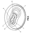
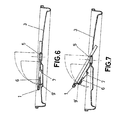
- FIG. 5 a variant of embodiment of the buffer for the end sector 8 of the lever 6 is shown, so that in this case, said buffer is formed by a flap 9' projected downward in an inclined manner, in order to constitute a ramp for the end edge of the end sector 8 which will initially retain this and therefore the lever 9' until the release is produced in the upward tilting of the main ring 1 as can be seen in figure 6 , which shows the rotating or tilting point wherein the aforementioned release is precisely produced,
- the secondary lever 6 remains arranged practically horizontally, as can be observed in figure 6 , with less risk of being accidentally actuated or pressed.
- FIG 5 shows the design is different from the previous figures, since the main ring 1 has a double lobe shape and a big window, whereas the secondary lever 6 is ovally widened and is also provided with a window.
- the secondary lever for making the opening of the orifices for air entrance may be made of aluminium, or even of a stamped iron strip, featuring a pre-fold at 10° directly above the rivet 5, wherein the section for ensuring the folded axis has been reduced, while the hammers 7 of said lever 6 are bent at 90° with respect to the upper face of the lever 6.
- the buffer for the secondary lever 6 instead of being formed by a flap, it is determined by a bridge lift 9" established at the end of the main ring 1, permitting the positioning of the finger end below said bridge lift 9" to facilitate the actuation or push upwards of said main ring 1 in the opening operation of the can or beverage container being dealt with.
- the main ring 1' lacks the secondary lever 6, so that in this case said main ring 1' has a lower end portion in the form of hammer 7' directed downward which will fall on the area of the lid outlined by the die cut 10' producing the tearing and corresponding opening of the orifice to allow the entrance of air,
- the tearing of the die cut 10' is performed after having tilted the main ring 1' upward to release the liquid outlet orifice, tearing which outlines the tongue 4, so that upon tilting the main ring 1' downward again until reaching its initial position and pressing on the end thereof, the lower end portion of the hammer 7' of said main ring 1', said hammer will fall on the area delimited by the aforementioned die cut 10', producing its tearing and therefore the opening of the air entrance orifice.
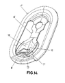
- a secondary lever 6' which has a central folding characteristic 12 formed by two downward converging planes which delimit a low relief projection constituting the corresponding hammer 7" facing a die cut unit 10" whose breaking determines the air entrance orifice.
- the secondary lever 6' also incorporates a characteristic angular configuration end sector 8', whereon the buffer 9' of the main ring 1" will fall.
- the outline delimited by the main ring 1" features a characteristic peripheral thickening of more ergonomic rounded cross-section, whose continuity is interrupted by a narrow portion 13 which facilitates the initiation of the lifting of the main ring 1".
- a characteristic bulge 14 in the shape of spherical cap delimited for the die cut 10" is shown, corresponding to the air entrance inside the can.
Landscapes
- Engineering & Computer Science (AREA)
- Mechanical Engineering (AREA)
- Ceramic Engineering (AREA)
- Chemical & Material Sciences (AREA)
- Combustion & Propulsion (AREA)
- Physics & Mathematics (AREA)
- Thermal Sciences (AREA)
- General Engineering & Computer Science (AREA)
- Containers Opened By Tearing Frangible Portions (AREA)
Abstract
Description
- The present invention, as the title of this specification states, relates to a double opening system for beverage cans for carrying out the execution of two openings in the corresponding upper lid of the beverage container or can being dealt with, with the object of allowing the exit of the liquid during its consumption and, in turn, the entrance of air for preventing the liquid to gush out messily.
- Another object of the present invention is to be able to perform the opening of the orifice for the entrance of air with a minimum effort by the user, further preventing the accidental opening of that orifice for air entrance.
- Beverage containers or cans generally present an upper lid for closing the mouth, the lid having a die cut determining a weakening line for obtaining, when the time comes, a beverage discharging orifice, a rivet for fastening a ring also existing next to this die cut whose retraction carries therewith the opening, when the tilting and pressing of said ring is carried out on the die cut area, producing the ripping thereof and therefore the opening of the can is established for allowing the liquid to exit.
- Clearly, the opening or orifice made in the mentioned manner, in addition to constituting the liquid exit means, also constitutes the means for air entrance, wherewith the liquid and the air collide and the liquid gushes out messily.
- In order to achieve the objectives and avoid the drawbacks mentioned in the previous paragraphs, the invention consists of a new double opening system for beverage cans which is centred, in principle, on the fact that the ring used for carrying out the tearing of the die cut which establishes the liquid outlet orifice, is complemented with a secondary lever pivotally mounted on the same rivet which mounts the main opening ring, with the special feature that that secondary lever always actuates subsequently to the main ring, to carry out the tearing of the die cut or die cuts corresponding to the air entrance, these being distanced from the die cut corresponding to the liquid outlet, with the special feature that the main ring has a wide window for allowing the tearing lever of the die cut to be placed thereon, which will lead to the air entrance orifice, the free end of this lever being supported on a buffer provided for this purpose on the main ring, for precisely preventing that lever from not acting until the tearing of the die cut which establishes the liquid outlet orifice by means of the main ring has been carried out.
- The secondary lever for tearing the die cut for the air entrance, and which is mounted on the same rivet as the main ring for tearing the die cut for liquid to exit, features one or two pointed hammers for perforating the lid, so that only a centred hammer would be desirable for the object of minimizing the user's efforts, although if not perfectly pressed in the direction perpendicular to the lid, the lever would twist without achieving tearing of the die cut, hence two hammers are arranged in a preferred embodiment, thus achieving that the lever is more stable in the pressing operation thereof to establish the orifice corresponding to the air entrance, with the possibility that one of the hammers can be blunt, so that it can only be used to stabilize the mechanism.
- The die cut or die cuts which are designed to be perforated or torn by the referred to hammer or hammers, shall either be arranged centrally when being a single die cut, or on one side and another of a deep-draw which provides rigidity to the zone and thus prevents the bulge of the lid in the opening processes, in the case of there being two die cuts.
- The hammer or hammers of the referred to secondary lever have a cutting profile for initiating a puncture of the die cut, and a subsequent pushing of the respective tongue for widening the initial break and increasing the orifice width.
- As mentioned previously, the main ring whereby the tearing of the die out for liquid exit is made, has a buffer for the free end of the aforementioned secondary lever, so that when the ring is pulled upward to carry out the correspondent opening during its tilting, it is dragged in tilting to the referred to lever to a point wherein this is released due to the fact that both elements (ring and lever) have different turning radii, so that when it is tilted upward from the main ring it takes the lever therewith, the lever being tilted until the end of said lever is released from the buffer established on the main ring for this purpose, whereby one side of the buffer prevents the accidental perforation of the die cuts for air entrance from being made, and on the other hand, once the tilting of the ring has been performed and the liquid outlet opening has been made, the lever can be pressed downward and its hammers can perform the corresponding opening.
- The buffer provided on the main ring for preventing the lever hammers from accidentally perforating and/or tearing the die cuts which establish the air entrance orifice or orifices, can be projected either inclining upward or downward, so that in any case the upward tilting of the main lever drags the lever along therewith to a point wherein the end thereof is released from the referred to buffer, as a consequence of the different turning radii of the ring and lever.
- In a variant of embodiment, said buffer can consist of a bridge lift of the end of the main ring, so that in addition to performing the buffer functions, it allows the introduction of the tip of one's finger for facilitating the pulling or upward pushing of said main ring.
- The arrangement and structure of the secondary lever permits one to increase the effort of tearing the die cut which will establish the opening or orifice for air entrance. This increased effort is achieved using the lever concept, strictly speaking.
- In a simpler embodiment, the secondary lever is dispensed with, so that in this case the main ring has a lower end portion which will fall on an area outlined by the die cut of the lid, executing the tearing thereof and thus releasing the air entrance orifice, after having previously released the liquid outlet orifice.
- In order to complement the description which is made below and with the object of helping towards a better understanding of the characteristics of the invention, the present specification is accompanied with a set of drawings whereby the innovations and advantages of the system made according to the object of the invention are more easily understood.
-
Figure 1 . - Shows a representation according to an upper perspective of a beverage can or container lid, with the double opening system for beverage cans. -
Figure 2 . Shows a plan view of the lid wherein the double opening system of the invention is applicable, and in whose lid the die cuts are made for both the opening of a liquid outlet orifice and air entrance openings, -
Figure 3 . -Shows a sectional view of the opening system applied on the lid represented in the previous figure, in a non-operative situation, -
Figure 4 . - Shows a sectional view such as that of the previous figure but after initiating the tilting of a main ring, dragging therewith a secondary lever, the position shown corresponding to the specific release point of said secondary lever with respect to the main ring. -
Figure 5 . - Shows a representation such as that fromfigure 1 , in a variant of embodiment of the shape or design of the double opening system, wherein a buffer of the main ring is projected inclining downward. -
Figure 6 . - Shows a sectional view such as the one fromfigure 3 , but with a buffer of the main ring projected downward, according to the embodiment of the previous figure. -
Figure 7 . - Shows a view equivalent to that offigure 4 , but with the version of the buffer represented infigures 5 and6 . -
Figure 8 . - Shows a representation such as that fromfigure 1 , wherein the secondary lever has a window, and the buffer of the main ring for said secondary lever consists of a bridge lift. -
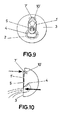
Figure 9 . - Shows a plan view of a beverage can lid with a double opening system which is simpler than the one represented in the previous figures.Figure 10 . - Shows an elevational view of that represented in the previous figure. -
Figures 11 to 13 . - Show respective views of the opening process of a can corresponding to the double opening system shown infigures 9 and 10 . -
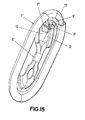
Figures 14 to 16 . - Show perspective views of a double opening system for beverage cans different from those shown in the previous figures. - As can be seen from the aforementioned figures, the double opening system for beverage cans according to the object of the invention, comprises a
main ring 1 wherethrough the tearing or cutting thedie cut 2 is performed, established in thecorresponding lid 3 of the beverage container or can, diecut 2 which delimits atongue 4 which, upon themain ring 1 being tilted ,through therivet 5 as articulation mounting element thereof, loosens thattongue 4 towards the interior to establish the liquid outlet orifice. - On the
same rivet 5 for tilting and mounting themain ring 1, asecondary lever 6 is mounted withcutting hammers 7,lever 6 which is located in a window provided for this purpose in themain ring 1, the end whereof presenting a narrowersmall sector 8, which rests on abuffer 9 emerging from themain ring 1, as clearly represented infigures 1 ,3 and 4 , so that in the resting position themain ring 1, as is conventional, remains attached on the top surface of thelid 3, and theend sector 8 of thelever 6 rests on the vertical flap of thebuffer 9, preventing thehammer 7 from falling on thelid 3, and specifically ondie cuts 10 established on saidlid 3, the breaking or tearing whereof, as explained later, carries therewith the formation of orifices for air entrance, allowing consumption of the liquid contained inside the can or container at the same time that the air enters through those orifices caused by detachment of the tongues delimited by diecuts 10, these being distant from the diecut 2 corresponding to the liquid outlet orifice, which makes it impossible for said liquid to exit through those orifices of thedie cuts 10 when the consumption is carried out. - i.e., based on the proposed characteristics and solution, the
main ring 1 and namely itsbuffer 9, block the movement of thelever 6 corresponding to thecutting hammers 7, it being necessary for themain ring 1 to carry out its upward movement to perform the breaking or tearing of thedie cut 2 corresponding to the liquid outlet orifice, in whose tilting themain ring 1 drags therewith thelever 6, which will also tilt upward, pivoting on therivet 5, until releasing that lever 6 of thering 1, namely, from thebuffer 9 thereof due to them having different turning radii, so that once the opening of the liquid outlet orifice is made, if themain ring 1 is pressed downward, thelever 6 is dragged and thehammers 7 fall on thedie cuts 10 producing the tearing and the corresponding opening of the orifices to permit the entrance or air. - Between the
die cuts 10 and to give a greater consistency to that area of the lid, a deep-draw 11 has been provided, as represented infigure 2 . - In
figures 5 ,6 and 7 , a variant of embodiment of the buffer for theend sector 8 of thelever 6 is shown, so that in this case, said buffer is formed by a flap 9' projected downward in an inclined manner, in order to constitute a ramp for the end edge of theend sector 8 which will initially retain this and therefore the lever 9' until the release is produced in the upward tilting of themain ring 1 as can be seen infigure 6 , which shows the rotating or tilting point wherein the aforementioned release is precisely produced, In this variant of embodiment, thesecondary lever 6 remains arranged practically horizontally, as can be observed infigure 6 , with less risk of being accidentally actuated or pressed. Additionally, it can be seen infigure 5 how the design is different from the previous figures, since themain ring 1 has a double lobe shape and a big window, whereas thesecondary lever 6 is ovally widened and is also provided with a window. - The secondary lever for making the opening of the orifices for air entrance may be made of aluminium, or even of a stamped iron strip, featuring a pre-fold at 10° directly above the
rivet 5, wherein the section for ensuring the folded axis has been reduced, while thehammers 7 ofsaid lever 6 are bent at 90° with respect to the upper face of thelever 6. - Finally, it must be said that the buffer for the
secondary lever 6, instead of being formed by a flap, it is determined by abridge lift 9" established at the end of themain ring 1, permitting the positioning of the finger end below saidbridge lift 9" to facilitate the actuation or push upwards of saidmain ring 1 in the opening operation of the can or beverage container being dealt with. - In
figures 9 and1 a simpler embodiment is shown, although less advantageous than that shown in the previous figures. - In said embodiment, the main ring 1' lacks the
secondary lever 6, so that in this case said main ring 1' has a lower end portion in the form of hammer 7' directed downward which will fall on the area of the lid outlined by the die cut 10' producing the tearing and corresponding opening of the orifice to allow the entrance of air, - As in the previously described embodiment, in the case of the simple embodiment (
figures 9 to 13 ), the tearing of the die cut 10' is performed after having tilted the main ring 1' upward to release the liquid outlet orifice, tearing which outlines thetongue 4, so that upon tilting the main ring 1' downward again until reaching its initial position and pressing on the end thereof, the lower end portion of the hammer 7' of said main ring 1', said hammer will fall on the area delimited by the aforementioned die cut 10', producing its tearing and therefore the opening of the air entrance orifice. - In
figures 14 and15 a third, more advantageous embodiment is shown wherein, starting from the embodiment shown infigures 1 to 8 , a secondary lever 6' is incorporated which has acentral folding characteristic 12 formed by two downward converging planes which delimit a low relief projection constituting thecorresponding hammer 7" facing adie cut unit 10" whose breaking determines the air entrance orifice. The secondary lever 6' also incorporates a characteristic angular configuration end sector 8', whereon the buffer 9' of themain ring 1" will fall. - In turn, the outline delimited by the
main ring 1" features a characteristic peripheral thickening of more ergonomic rounded cross-section, whose continuity is interrupted by anarrow portion 13 which facilitates the initiation of the lifting of themain ring 1". - In figure 16, a characteristic bulge 14 in the shape of spherical cap delimited for the
die cut 10" is shown, corresponding to the air entrance inside the can. - Nevertheless, this bulge is also applicable to the die cuts 10-10' of the other two embodiments.
Claims (14)
- DOUBLE OPENING SYSTEM FOR BEVERAGE CANS, wherein the corresponding lid of the beverage can features a die cut sector intended to be torn so as to establish an outlet orifice of the liquid contained in the can, the tearing of the die cut being performed by means o fan upward tilting of a main ring mounted on a rivet established for this purpose on the lid characterized in that the lid incorporates at least a second die cut (10-10'-10") whose tearing constitutes an air entrance orifice, die cut which delimits a portion of lid facing the respective cutting hammer (7-7'-7") for its tearing, this tearing being performed by tilting the main ring downward until its initial resting position, after having first torn the liquid outlet orifice.
- DOUBLE OPENING SYSTEM FOR BEVERAGE CANS, according to claim 1, characterized in that DOUBLE OPENING SYSTEM FOR BEVERAGE CANS, according to clam 1, characterized in that mounted on the same tiling rivet (5) of the main ring (1-1") is a secondary lever (6-6') for tearing of the die cut or die cuts (10-10") by pressing downwards on said secondary lever (6-6') after tilting the main ring (1-1") upwards and tearing the liquid exit die cut (2); it having been provided that said secondary lever (6-6') has, at least, the respective cutting hammer (7-7") for the tearing of the die cut or die cuts (10-10").
- DOUBLE OPENING SYSTEM FOR BEVERAGE CANS, according to claim 2, characterized in that the secondary lever (6-6') for tearing of the die cut or die cuts (10-10") features an end sector (8-8') which determines a support on a buffer (9 or 90 or 9") established on the main ring (1-1") to prevent the cutting hammer (7-7") from falling on the die cut or die cuts (10-10") before performing the tilting of the main ring (1-1") to carry out the tearing of the die cut (2).
- DOUBLE OPENING SYSTEM FOR BEVERAGE CANS, according to claim 2, characterized in that the main ring (1-1") is provided with a wide locating window for the secondary lever (6-6').
- DOUBLE OPENING SYSTEM FOR BEVERAGE CANS, according to claims 2 to 4. characterized in that the tilting axis of the main ring (1-1") is different from the tilting axis of the secondary ring (6-6'), so that the tilting of the main ring (1-1 ") to perform the tearing different from the tilting axis of the secondary ring (6-6'), so that the tilting of the main ring (1-1") to perform the tearing of the die cut (2) initially drags the secondary lever (6-6') until the end sector (8-8') is released from the buffer (9 or 9' or 9") of said main ring (1), while in the downward tilting of said main ring (1) after the tearing of the de out (2), the downward dragging of the second lever (6-6') is taken with it, producing, in the pressing thereof on the lid (39, the tearing of the die cut or die cuts (10) by the cutting hammer or hammers (7-7") of said secondary lever (6-6').
- DOUBLE OPENING SYSTEM FOR BEVERAGE CANS, according to claims 2 to 5, characterized in that the buffer (9) for the narrow end sector (8) of the secondary lever (6), is determined by an upwards projecting flap.
- DOUBLE OPENING SYSTEM FOR BEVERAGE CANS, according to claims 2 to 5, characterized in that the buffer (8') for the end sector (8) of the secondary lever (6) is determined by a downward tilting flap, establishing a support ramp and buffer for said end sector (8).
- DOUBLE OPENING SYSTEM FOR BEVERAGE CANS, according to claims 2 to 5, characterized in that the buffer for the end sector (8) of the secondary lever (6) is determined by a bridge lift (9") corresponding to the end of the main ring (1).
- DOUBLE OPENING SYSTEM FOR BEVERAGE CANS, according to claim 3, characterized in that the end sector (8') of the secondary lever (6) comprises a small extension which is a prolongation of the secondary lever (6).
- DOUBLE OPENING SYSTEM FOR BEVERAGE CANS, according to claim 3, characterized in that the end sector (8') of the secondary lever (6') features an angular configuration.
- DOUBLE OPENING SYSTEM FOR BEVERAGE CANS, according to claim 2, characterized in that the secondary lever (6') has a centred fold (12) forming two downward converging planes which delimit a centred low relief end projection which constitutes the hammer (7").
- DOUBLE OPENING SYSTEM FOR BEVERAGE CANS, according to claim 2, characterized in that the main ring (1") features a peripheral thickening of rounded cross-section which is interrupted by a narrow portion (13).
- DOUBLE OPENING SYSTEM FOR BEVERAGE CANS, according to any of the previous claim, characterized in that the area delimited by the die cut (10-10'-10") comprises a bulge (14).
- DOUBLE OPENING SYSTEM FOR BEVERAGE CANS, according to claim 13, characterized in that the bulge (14) features a structure in the shape of a spherical cap.
Applications Claiming Priority (3)
| Application Number | Priority Date | Filing Date | Title |
|---|---|---|---|
| ES200802979A ES2343719B1 (en) | 2008-10-22 | 2008-10-22 | DOUBLE OPENING SYSTEM FOR DRINK CANS. |
| ES200900747A ES2345314B1 (en) | 2008-10-22 | 2009-03-18 | IMPROVEMENTS INTRODUCED IN THE MAIN INVENTION PATENT N. P-200802979/4 BY: DOUBLE OPENING SYSTEM FOR DRINKED CAN. |
| PCT/ES2009/070448 WO2010046516A1 (en) | 2008-10-22 | 2009-10-21 | Double opening system for beverage cans |
Publications (3)
| Publication Number | Publication Date |
|---|---|
| EP2364921A1 true EP2364921A1 (en) | 2011-09-14 |
| EP2364921A4 EP2364921A4 (en) | 2012-07-25 |
| EP2364921B1 EP2364921B1 (en) | 2014-01-22 |
Family
ID=42118978
Family Applications (1)
| Application Number | Title | Priority Date | Filing Date |
|---|---|---|---|
| EP09821631.0A Active EP2364921B1 (en) | 2008-10-22 | 2009-10-21 | Double opening system for beverage cans |
Country Status (11)
| Country | Link |
|---|---|
| US (1) | US8939306B2 (en) |
| EP (1) | EP2364921B1 (en) |
| JP (1) | JP5607057B2 (en) |
| KR (1) | KR101801986B1 (en) |
| CN (1) | CN102202981A (en) |
| AU (1) | AU2009306324A1 (en) |
| CA (1) | CA2740953C (en) |
| CO (1) | CO6361974A2 (en) |
| EC (1) | ECSP11010988A (en) |
| PE (1) | PE20120201A1 (en) |
| WO (1) | WO2010046516A1 (en) |
Families Citing this family (30)
| Publication number | Priority date | Publication date | Assignee | Title |
|---|---|---|---|---|
| US8397935B2 (en) | 2009-09-10 | 2013-03-19 | Arthur Joseph Emanuele, III | Vent opening mechanism |
| US8678221B2 (en) | 2010-04-28 | 2014-03-25 | Crown Packaging Technology, Inc. | Beverage container lid with mouth opening and separate push in vent |
| US8567158B2 (en) | 2010-08-06 | 2013-10-29 | Ball Corporation | Container end closure with optional secondary vent opening |
| US10017295B2 (en) | 2010-08-06 | 2018-07-10 | Ball Corporation | Container end closure with optional secondary vent opening |
| US20120199586A1 (en) * | 2011-02-08 | 2012-08-09 | Gregory Randall Shamalta | Lid for a beverage can |
| US8127588B1 (en) | 2011-03-23 | 2012-03-06 | Halpin Harold W | Apparatus and methods for forming a finger-engaging portion in a stay-on-tab of a lid of a container |
| WO2013022592A1 (en) | 2011-08-11 | 2013-02-14 | Stolle Machinery Company, Llc | Can end, double action tab therefor, tooling assembly, and associated method |
| USD691039S1 (en) | 2011-10-27 | 2013-10-08 | Ball Corporation | Vented container end closure |
| EP2773572B1 (en) | 2011-11-04 | 2019-08-28 | Ball Corporation | Vented metallic container end closure |
| ES2403165B1 (en) * | 2011-11-08 | 2014-06-17 | Oscar LORENZANA IGLESIAS | OPENING DEVICE FOR DRINK CAN |
| ES2574903T3 (en) * | 2011-12-20 | 2016-06-23 | Ardagh Mp Group Netherlands B.V. | Panel and container provided with said panel |
| EP2612822A1 (en) | 2012-01-03 | 2013-07-10 | Anheuser-Busch InBev S.A. | Can comprising a first, dispense opening and second, vent opening and a single pull tab |
| EP2612821A1 (en) | 2012-01-03 | 2013-07-10 | Anheuser-Busch InBev S.A. | Can comprising a first, dispense opening and second, vent opening |
| EP2612823A1 (en) * | 2012-01-03 | 2013-07-10 | Anheuser-Busch InBev S.A. | Can comprising a maxi-dispense opening and a vent opening |
| US9156585B2 (en) * | 2012-04-04 | 2015-10-13 | Anheuser-Busch Inbev S.A. | Double opening beverage can lid system |
| US8783496B2 (en) | 2012-04-04 | 2014-07-22 | Anheuser-Busch InBev, SA | Double-opening can lid |
| USD678784S1 (en) | 2012-06-18 | 2013-03-26 | Ricardo M. Aranha | Dual opening beverage can |
| USD708060S1 (en) | 2012-07-11 | 2014-07-01 | Anheuser-Busche InBev, SA | Can opening tab with large head |
| USD708516S1 (en) | 2012-07-11 | 2014-07-08 | Anheuser-Busch InBev, SA | Can opening tab |
| USD715144S1 (en) | 2012-11-13 | 2014-10-14 | Ball Corporation | Vented container end closure |
| USD715647S1 (en) | 2012-11-28 | 2014-10-21 | Ball Corporation | Vented end closure |
| US9403628B2 (en) | 2013-03-14 | 2016-08-02 | Crown Packaging Technology, Inc. | Vented beverage can and can end |
| US10246229B2 (en) | 2013-03-14 | 2019-04-02 | Crown Packaging Technology, Inc. | Vented beverage can and can end |
| US9694935B2 (en) | 2013-03-15 | 2017-07-04 | Ball Corporation | End closure with a ring pull actuated secondary vent |
| CN105246650B (en) | 2013-03-15 | 2017-06-09 | 四站有限责任公司 | The apparatus and method of the draw ring on bending container |
| US20150353228A1 (en) * | 2013-06-10 | 2015-12-10 | Adam Herriott | Can/flass soda can. The new can opening. |
| CN106604871A (en) | 2014-07-30 | 2017-04-26 | 鲍尔公司 | Vented container end closure |
| MX389384B (en) | 2014-08-19 | 2025-03-20 | Ball Corp | METAL END CLOSURE WITH AN EXTENDED NOTCH THAT OPENS WITH A SECONDARY TOOL. |
| US11305921B1 (en) | 2019-08-23 | 2022-04-19 | Planet Canit, Llc | Lever lid container with child-resistant lid release |
| RU198900U1 (en) * | 2019-11-11 | 2020-07-31 | Беслан Шудиевич Дадакаев | LID WITH DOUBLE LEAF FOR METAL CANS |
Family Cites Families (16)
| Publication number | Priority date | Publication date | Assignee | Title |
|---|---|---|---|---|
| US4872597A (en) * | 1988-10-13 | 1989-10-10 | Hisao Hanafusa | Beverage container with dual dispensing tabs |
| US5011037A (en) * | 1989-11-30 | 1991-04-30 | Adolph Coors Company | Container end member |
| US5285919A (en) * | 1992-12-30 | 1994-02-15 | Donald Recchia | Beverage container with air access for direct drinking |
| JP3468548B2 (en) * | 1993-06-30 | 2003-11-17 | 三菱マテリアル株式会社 | Stay-tab type can lid |
| US5397014A (en) * | 1993-12-22 | 1995-03-14 | Aydt; Robert | Dual aperture retained tab |
| JPH0853130A (en) * | 1994-08-09 | 1996-02-27 | Mitsubishi Materials Corp | Can lid, can container and can lid opening method |
| JP3009064U (en) * | 1994-09-16 | 1995-03-28 | 俊幸 佐藤 | Opening device for canned beverages |
| JPH1035662A (en) * | 1996-07-23 | 1998-02-10 | Takaaki Kuga | Easy-to-open deaerating hole in easy-to-open can lid |
| US5695085A (en) * | 1996-10-11 | 1997-12-09 | Hadener; Albert K. | Beverage can with an opener |
| US5819973A (en) * | 1996-12-31 | 1998-10-13 | Traub, Sr.; John J. | Beverage container lid having a lift tab for opening an aperture and vent hole |
| JPH10245032A (en) * | 1997-03-06 | 1998-09-14 | Katsumasa Koshimura | Can lid |
| KR200191406Y1 (en) | 2000-02-14 | 2000-08-16 | 김태승 | Easy aluminum canopener |
| KR100387622B1 (en) * | 2002-10-18 | 2003-06-18 | Bo Yeoun Hwang | Can opening apparatus |
| KR200328730Y1 (en) | 2003-06-27 | 2003-10-04 | 최창수 | can to have boring-pin |
| JP2007062758A (en) * | 2005-08-30 | 2007-03-15 | Kazunori Abiko | Can with stay-on tab |
| NL2000193C2 (en) * | 2006-08-23 | 2008-02-26 | 4Sight Innovation Bv | Closing element for a beverage can and beverage can provided with such a closing element. |
-
2009
- 2009-10-21 JP JP2011532674A patent/JP5607057B2/en not_active Expired - Fee Related
- 2009-10-21 PE PE2011000908A patent/PE20120201A1/en active IP Right Grant
- 2009-10-21 US US13/000,718 patent/US8939306B2/en active Active
- 2009-10-21 EP EP09821631.0A patent/EP2364921B1/en active Active
- 2009-10-21 AU AU2009306324A patent/AU2009306324A1/en not_active Abandoned
- 2009-10-21 WO PCT/ES2009/070448 patent/WO2010046516A1/en not_active Ceased
- 2009-10-21 KR KR1020117011582A patent/KR101801986B1/en active Active
- 2009-10-21 CA CA2740953A patent/CA2740953C/en active Active
- 2009-10-21 CN CN200980142302XA patent/CN102202981A/en active Pending
-
2011
- 2011-04-15 EC EC2011010988A patent/ECSP11010988A/en unknown
- 2011-04-20 CO CO11049765A patent/CO6361974A2/en active IP Right Grant
Also Published As
| Publication number | Publication date |
|---|---|
| US8939306B2 (en) | 2015-01-27 |
| EP2364921A4 (en) | 2012-07-25 |
| AU2009306324A1 (en) | 2010-04-29 |
| PE20120201A1 (en) | 2012-02-25 |
| EP2364921B1 (en) | 2014-01-22 |
| JP5607057B2 (en) | 2014-10-15 |
| US20110108552A1 (en) | 2011-05-12 |
| KR101801986B1 (en) | 2018-01-17 |
| CA2740953C (en) | 2018-10-30 |
| WO2010046516A1 (en) | 2010-04-29 |
| CN102202981A (en) | 2011-09-28 |
| KR20110088525A (en) | 2011-08-03 |
| JP2012506348A (en) | 2012-03-15 |
| ECSP11010988A (en) | 2011-06-30 |
| CO6361974A2 (en) | 2012-01-20 |
| CA2740953A1 (en) | 2010-04-29 |
Similar Documents
| Publication | Publication Date | Title |
|---|---|---|
| CA2740953C (en) | Double opening system for beverage cans | |
| AU2016204140A1 (en) | Double Opening System for Beverage Cans | |
| JPH08268429A (en) | Easily openable can lid and method for opening the lid | |
| CN104364164B (en) | Ventilation metal end, ventilation container for drink and the method for opening container for drink | |
| US3836038A (en) | Easy-open wall | |
| US9884701B2 (en) | Ecology can end with pressure equalization port | |
| EP3248897B1 (en) | Beverage can end with vent port | |
| US3338463A (en) | Pull tab container opener | |
| EP2448834B1 (en) | Lid for containers of substances and container of substances thus equipped | |
| US20120273492A1 (en) | Ergonomic Stay-On Tab | |
| USRE30349E (en) | Easy-opening container wall with coreline vent | |
| JPS6233140B2 (en) | ||
| US3850124A (en) | Easy opening container wall | |
| US20170057692A1 (en) | Constructive arrangement for the opening of a beverage can | |
| US3485411A (en) | Tab for easy-opening container | |
| JP2007308142A (en) | Can lid | |
| JP2006069605A (en) | Steion tab type can lid | |
| JPH0120268Y2 (en) | ||
| JPH0339382Y2 (en) | ||
| JP7096262B2 (en) | Structural arrangement for the opening of the beverage can | |
| JPH0120269Y2 (en) |
Legal Events
| Date | Code | Title | Description |
|---|---|---|---|
| PUAI | Public reference made under article 153(3) epc to a published international application that has entered the european phase |
Free format text: ORIGINAL CODE: 0009012 |
|
| 17P | Request for examination filed |
Effective date: 20110519 |
|
| AK | Designated contracting states |
Kind code of ref document: A1 Designated state(s): AT BE BG CH CY CZ DE DK EE ES FI FR GB GR HR HU IE IS IT LI LT LU LV MC MK MT NL NO PL PT RO SE SI SK SM TR |
|
| AX | Request for extension of the european patent |
Extension state: AL BA RS |
|
| A4 | Supplementary search report drawn up and despatched |
Effective date: 20120627 |
|
| RIC1 | Information provided on ipc code assigned before grant |
Ipc: B65D 17/34 20060101AFI20120621BHEP |
|
| RAP1 | Party data changed (applicant data changed or rights of an application transferred) |
Owner name: ANHEUSER-BUSCH INBEV S.A. |
|
| RIN1 | Information on inventor provided before grant (corrected) |
Inventor name: ANHEUSER-BUSCH INBEV S.A. |
|
| 17Q | First examination report despatched |
Effective date: 20130215 |
|
| RIN1 | Information on inventor provided before grant (corrected) |
Inventor name: TAMARIT RIOS, RAMON |
|
| GRAP | Despatch of communication of intention to grant a patent |
Free format text: ORIGINAL CODE: EPIDOSNIGR1 |
|
| INTG | Intention to grant announced |
Effective date: 20130902 |
|
| GRAS | Grant fee paid |
Free format text: ORIGINAL CODE: EPIDOSNIGR3 |
|
| GRAA | (expected) grant |
Free format text: ORIGINAL CODE: 0009210 |
|
| AK | Designated contracting states |
Kind code of ref document: B1 Designated state(s): AT BE BG CH CY CZ DE DK EE ES FI FR GB GR HR HU IE IS IT LI LT LU LV MC MK MT NL NO PL PT RO SE SI SK SM TR |
|
| AX | Request for extension of the european patent |
Extension state: AL BA RS |
|
| REG | Reference to a national code |
Ref country code: GB Ref legal event code: FG4D |
|
| REG | Reference to a national code |
Ref country code: CH Ref legal event code: EP |
|
| REG | Reference to a national code |
Ref country code: AT Ref legal event code: REF Ref document number: 650685 Country of ref document: AT Kind code of ref document: T Effective date: 20140215 |
|
| REG | Reference to a national code |
Ref country code: IE Ref legal event code: FG4D |
|
| REG | Reference to a national code |
Ref country code: DE Ref legal event code: R096 Ref document number: 602009021651 Country of ref document: DE Effective date: 20140306 |
|
| REG | Reference to a national code |
Ref country code: NL Ref legal event code: T3 |
|
| REG | Reference to a national code |
Ref country code: ES Ref legal event code: FG2A Ref document number: 2458098 Country of ref document: ES Kind code of ref document: T3 Effective date: 20140429 |
|
| REG | Reference to a national code |
Ref country code: DK Ref legal event code: T3 Effective date: 20140428 |
|
| REG | Reference to a national code |
Ref country code: AT Ref legal event code: MK05 Ref document number: 650685 Country of ref document: AT Kind code of ref document: T Effective date: 20140122 |
|
| REG | Reference to a national code |
Ref country code: LT Ref legal event code: MG4D |
|
| PG25 | Lapsed in a contracting state [announced via postgrant information from national office to epo] |
Ref country code: IS Free format text: LAPSE BECAUSE OF FAILURE TO SUBMIT A TRANSLATION OF THE DESCRIPTION OR TO PAY THE FEE WITHIN THE PRESCRIBED TIME-LIMIT Effective date: 20140522 Ref country code: NO Free format text: LAPSE BECAUSE OF FAILURE TO SUBMIT A TRANSLATION OF THE DESCRIPTION OR TO PAY THE FEE WITHIN THE PRESCRIBED TIME-LIMIT Effective date: 20140422 Ref country code: LT Free format text: LAPSE BECAUSE OF FAILURE TO SUBMIT A TRANSLATION OF THE DESCRIPTION OR TO PAY THE FEE WITHIN THE PRESCRIBED TIME-LIMIT Effective date: 20140122 |
|
| PG25 | Lapsed in a contracting state [announced via postgrant information from national office to epo] |
Ref country code: SE Free format text: LAPSE BECAUSE OF FAILURE TO SUBMIT A TRANSLATION OF THE DESCRIPTION OR TO PAY THE FEE WITHIN THE PRESCRIBED TIME-LIMIT Effective date: 20140122 Ref country code: PT Free format text: LAPSE BECAUSE OF FAILURE TO SUBMIT A TRANSLATION OF THE DESCRIPTION OR TO PAY THE FEE WITHIN THE PRESCRIBED TIME-LIMIT Effective date: 20140522 Ref country code: AT Free format text: LAPSE BECAUSE OF FAILURE TO SUBMIT A TRANSLATION OF THE DESCRIPTION OR TO PAY THE FEE WITHIN THE PRESCRIBED TIME-LIMIT Effective date: 20140122 Ref country code: CY Free format text: LAPSE BECAUSE OF FAILURE TO SUBMIT A TRANSLATION OF THE DESCRIPTION OR TO PAY THE FEE WITHIN THE PRESCRIBED TIME-LIMIT Effective date: 20140122 Ref country code: FI Free format text: LAPSE BECAUSE OF FAILURE TO SUBMIT A TRANSLATION OF THE DESCRIPTION OR TO PAY THE FEE WITHIN THE PRESCRIBED TIME-LIMIT Effective date: 20140122 |
|
| PG25 | Lapsed in a contracting state [announced via postgrant information from national office to epo] |
Ref country code: LV Free format text: LAPSE BECAUSE OF FAILURE TO SUBMIT A TRANSLATION OF THE DESCRIPTION OR TO PAY THE FEE WITHIN THE PRESCRIBED TIME-LIMIT Effective date: 20140122 Ref country code: HR Free format text: LAPSE BECAUSE OF FAILURE TO SUBMIT A TRANSLATION OF THE DESCRIPTION OR TO PAY THE FEE WITHIN THE PRESCRIBED TIME-LIMIT Effective date: 20140122 |
|
| REG | Reference to a national code |
Ref country code: DE Ref legal event code: R097 Ref document number: 602009021651 Country of ref document: DE |
|
| PG25 | Lapsed in a contracting state [announced via postgrant information from national office to epo] |
Ref country code: EE Free format text: LAPSE BECAUSE OF FAILURE TO SUBMIT A TRANSLATION OF THE DESCRIPTION OR TO PAY THE FEE WITHIN THE PRESCRIBED TIME-LIMIT Effective date: 20140122 Ref country code: RO Free format text: LAPSE BECAUSE OF FAILURE TO SUBMIT A TRANSLATION OF THE DESCRIPTION OR TO PAY THE FEE WITHIN THE PRESCRIBED TIME-LIMIT Effective date: 20140122 |
|
| PG25 | Lapsed in a contracting state [announced via postgrant information from national office to epo] |
Ref country code: PL Free format text: LAPSE BECAUSE OF FAILURE TO SUBMIT A TRANSLATION OF THE DESCRIPTION OR TO PAY THE FEE WITHIN THE PRESCRIBED TIME-LIMIT Effective date: 20140122 Ref country code: SK Free format text: LAPSE BECAUSE OF FAILURE TO SUBMIT A TRANSLATION OF THE DESCRIPTION OR TO PAY THE FEE WITHIN THE PRESCRIBED TIME-LIMIT Effective date: 20140122 |
|
| PLBE | No opposition filed within time limit |
Free format text: ORIGINAL CODE: 0009261 |
|
| STAA | Information on the status of an ep patent application or granted ep patent |
Free format text: STATUS: NO OPPOSITION FILED WITHIN TIME LIMIT |
|
| 26N | No opposition filed |
Effective date: 20141023 |
|
| REG | Reference to a national code |
Ref country code: DE Ref legal event code: R097 Ref document number: 602009021651 Country of ref document: DE Effective date: 20141023 |
|
| PG25 | Lapsed in a contracting state [announced via postgrant information from national office to epo] |
Ref country code: SI Free format text: LAPSE BECAUSE OF FAILURE TO SUBMIT A TRANSLATION OF THE DESCRIPTION OR TO PAY THE FEE WITHIN THE PRESCRIBED TIME-LIMIT Effective date: 20140122 Ref country code: MC Free format text: LAPSE BECAUSE OF FAILURE TO SUBMIT A TRANSLATION OF THE DESCRIPTION OR TO PAY THE FEE WITHIN THE PRESCRIBED TIME-LIMIT Effective date: 20140122 Ref country code: LU Free format text: LAPSE BECAUSE OF FAILURE TO SUBMIT A TRANSLATION OF THE DESCRIPTION OR TO PAY THE FEE WITHIN THE PRESCRIBED TIME-LIMIT Effective date: 20141021 |
|
| REG | Reference to a national code |
Ref country code: CH Ref legal event code: PL |
|
| PG25 | Lapsed in a contracting state [announced via postgrant information from national office to epo] |
Ref country code: LI Free format text: LAPSE BECAUSE OF NON-PAYMENT OF DUE FEES Effective date: 20141031 Ref country code: CH Free format text: LAPSE BECAUSE OF NON-PAYMENT OF DUE FEES Effective date: 20141031 |
|
| REG | Reference to a national code |
Ref country code: FR Ref legal event code: PLFP Year of fee payment: 7 |
|
| PG25 | Lapsed in a contracting state [announced via postgrant information from national office to epo] |
Ref country code: SM Free format text: LAPSE BECAUSE OF FAILURE TO SUBMIT A TRANSLATION OF THE DESCRIPTION OR TO PAY THE FEE WITHIN THE PRESCRIBED TIME-LIMIT Effective date: 20140122 |
|
| PG25 | Lapsed in a contracting state [announced via postgrant information from national office to epo] |
Ref country code: GR Free format text: LAPSE BECAUSE OF FAILURE TO SUBMIT A TRANSLATION OF THE DESCRIPTION OR TO PAY THE FEE WITHIN THE PRESCRIBED TIME-LIMIT Effective date: 20140423 Ref country code: BG Free format text: LAPSE BECAUSE OF FAILURE TO SUBMIT A TRANSLATION OF THE DESCRIPTION OR TO PAY THE FEE WITHIN THE PRESCRIBED TIME-LIMIT Effective date: 20140122 |
|
| PG25 | Lapsed in a contracting state [announced via postgrant information from national office to epo] |
Ref country code: TR Free format text: LAPSE BECAUSE OF FAILURE TO SUBMIT A TRANSLATION OF THE DESCRIPTION OR TO PAY THE FEE WITHIN THE PRESCRIBED TIME-LIMIT Effective date: 20140122 Ref country code: HU Free format text: LAPSE BECAUSE OF FAILURE TO SUBMIT A TRANSLATION OF THE DESCRIPTION OR TO PAY THE FEE WITHIN THE PRESCRIBED TIME-LIMIT; INVALID AB INITIO Effective date: 20091021 Ref country code: MT Free format text: LAPSE BECAUSE OF FAILURE TO SUBMIT A TRANSLATION OF THE DESCRIPTION OR TO PAY THE FEE WITHIN THE PRESCRIBED TIME-LIMIT Effective date: 20140122 |
|
| REG | Reference to a national code |
Ref country code: FR Ref legal event code: PLFP Year of fee payment: 8 |
|
| REG | Reference to a national code |
Ref country code: FR Ref legal event code: PLFP Year of fee payment: 9 |
|
| PG25 | Lapsed in a contracting state [announced via postgrant information from national office to epo] |
Ref country code: MK Free format text: LAPSE BECAUSE OF FAILURE TO SUBMIT A TRANSLATION OF THE DESCRIPTION OR TO PAY THE FEE WITHIN THE PRESCRIBED TIME-LIMIT Effective date: 20140122 |
|
| REG | Reference to a national code |
Ref country code: FR Ref legal event code: PLFP Year of fee payment: 10 |
|
| PGFP | Annual fee paid to national office [announced via postgrant information from national office to epo] |
Ref country code: IE Payment date: 20211020 Year of fee payment: 13 Ref country code: DK Payment date: 20211022 Year of fee payment: 13 Ref country code: ES Payment date: 20211223 Year of fee payment: 13 Ref country code: CZ Payment date: 20211021 Year of fee payment: 13 |
|
| PGFP | Annual fee paid to national office [announced via postgrant information from national office to epo] |
Ref country code: IT Payment date: 20211028 Year of fee payment: 13 |
|
| REG | Reference to a national code |
Ref country code: DK Ref legal event code: EBP Effective date: 20221031 |
|
| P01 | Opt-out of the competence of the unified patent court (upc) registered |
Effective date: 20230527 |
|
| PG25 | Lapsed in a contracting state [announced via postgrant information from national office to epo] |
Ref country code: CZ Free format text: LAPSE BECAUSE OF NON-PAYMENT OF DUE FEES Effective date: 20221021 |
|
| PG25 | Lapsed in a contracting state [announced via postgrant information from national office to epo] |
Ref country code: IT Free format text: LAPSE BECAUSE OF NON-PAYMENT OF DUE FEES Effective date: 20221021 Ref country code: IE Free format text: LAPSE BECAUSE OF NON-PAYMENT OF DUE FEES Effective date: 20221021 Ref country code: DK Free format text: LAPSE BECAUSE OF NON-PAYMENT OF DUE FEES Effective date: 20221031 |
|
| REG | Reference to a national code |
Ref country code: ES Ref legal event code: FD2A Effective date: 20231129 |
|
| PG25 | Lapsed in a contracting state [announced via postgrant information from national office to epo] |
Ref country code: ES Free format text: LAPSE BECAUSE OF NON-PAYMENT OF DUE FEES Effective date: 20221022 |
|
| PG25 | Lapsed in a contracting state [announced via postgrant information from national office to epo] |
Ref country code: ES Free format text: LAPSE BECAUSE OF NON-PAYMENT OF DUE FEES Effective date: 20221022 |
|
| PGFP | Annual fee paid to national office [announced via postgrant information from national office to epo] |
Ref country code: NL Payment date: 20251021 Year of fee payment: 17 |
|
| PGFP | Annual fee paid to national office [announced via postgrant information from national office to epo] |
Ref country code: DE Payment date: 20251021 Year of fee payment: 17 |
|
| PGFP | Annual fee paid to national office [announced via postgrant information from national office to epo] |
Ref country code: GB Payment date: 20251022 Year of fee payment: 17 |
|
| PGFP | Annual fee paid to national office [announced via postgrant information from national office to epo] |
Ref country code: FR Payment date: 20251029 Year of fee payment: 17 |
|
| PGFP | Annual fee paid to national office [announced via postgrant information from national office to epo] |
Ref country code: BE Payment date: 20251021 Year of fee payment: 17 |