EP2364891A1 - Method for threat assessment in a vehicle - Google Patents
Method for threat assessment in a vehicle Download PDFInfo
- Publication number
- EP2364891A1 EP2364891A1 EP10156390A EP10156390A EP2364891A1 EP 2364891 A1 EP2364891 A1 EP 2364891A1 EP 10156390 A EP10156390 A EP 10156390A EP 10156390 A EP10156390 A EP 10156390A EP 2364891 A1 EP2364891 A1 EP 2364891A1
- Authority
- EP
- European Patent Office
- Prior art keywords
- vehicle
- driver
- constraints
- safe
- sequence
- Prior art date
- Legal status (The legal status is an assumption and is not a legal conclusion. Google has not performed a legal analysis and makes no representation as to the accuracy of the status listed.)
- Granted
Links
Images


Classifications
-
- B—PERFORMING OPERATIONS; TRANSPORTING
- B60—VEHICLES IN GENERAL
- B60W—CONJOINT CONTROL OF VEHICLE SUB-UNITS OF DIFFERENT TYPE OR DIFFERENT FUNCTION; CONTROL SYSTEMS SPECIALLY ADAPTED FOR HYBRID VEHICLES; ROAD VEHICLE DRIVE CONTROL SYSTEMS FOR PURPOSES NOT RELATED TO THE CONTROL OF A PARTICULAR SUB-UNIT
- B60W40/00—Estimation or calculation of non-directly measurable driving parameters for road vehicle drive control systems not related to the control of a particular sub unit, e.g. by using mathematical models
- B60W40/02—Estimation or calculation of non-directly measurable driving parameters for road vehicle drive control systems not related to the control of a particular sub unit, e.g. by using mathematical models related to ambient conditions
- B60W40/06—Road conditions
- B60W40/072—Curvature of the road
-
- B—PERFORMING OPERATIONS; TRANSPORTING
- B60—VEHICLES IN GENERAL
- B60W—CONJOINT CONTROL OF VEHICLE SUB-UNITS OF DIFFERENT TYPE OR DIFFERENT FUNCTION; CONTROL SYSTEMS SPECIALLY ADAPTED FOR HYBRID VEHICLES; ROAD VEHICLE DRIVE CONTROL SYSTEMS FOR PURPOSES NOT RELATED TO THE CONTROL OF A PARTICULAR SUB-UNIT
- B60W40/00—Estimation or calculation of non-directly measurable driving parameters for road vehicle drive control systems not related to the control of a particular sub unit, e.g. by using mathematical models
- B60W40/02—Estimation or calculation of non-directly measurable driving parameters for road vehicle drive control systems not related to the control of a particular sub unit, e.g. by using mathematical models related to ambient conditions
- B60W40/06—Road conditions
- B60W40/076—Slope angle of the road
-
- B—PERFORMING OPERATIONS; TRANSPORTING
- B60—VEHICLES IN GENERAL
- B60W—CONJOINT CONTROL OF VEHICLE SUB-UNITS OF DIFFERENT TYPE OR DIFFERENT FUNCTION; CONTROL SYSTEMS SPECIALLY ADAPTED FOR HYBRID VEHICLES; ROAD VEHICLE DRIVE CONTROL SYSTEMS FOR PURPOSES NOT RELATED TO THE CONTROL OF A PARTICULAR SUB-UNIT
- B60W40/00—Estimation or calculation of non-directly measurable driving parameters for road vehicle drive control systems not related to the control of a particular sub unit, e.g. by using mathematical models
- B60W40/10—Estimation or calculation of non-directly measurable driving parameters for road vehicle drive control systems not related to the control of a particular sub unit, e.g. by using mathematical models related to vehicle motion
-
- B—PERFORMING OPERATIONS; TRANSPORTING
- B60—VEHICLES IN GENERAL
- B60W—CONJOINT CONTROL OF VEHICLE SUB-UNITS OF DIFFERENT TYPE OR DIFFERENT FUNCTION; CONTROL SYSTEMS SPECIALLY ADAPTED FOR HYBRID VEHICLES; ROAD VEHICLE DRIVE CONTROL SYSTEMS FOR PURPOSES NOT RELATED TO THE CONTROL OF A PARTICULAR SUB-UNIT
- B60W50/00—Details of control systems for road vehicle drive control not related to the control of a particular sub-unit, e.g. process diagnostic or vehicle driver interfaces
- B60W50/0097—Predicting future conditions
-
- B—PERFORMING OPERATIONS; TRANSPORTING
- B60—VEHICLES IN GENERAL
- B60W—CONJOINT CONTROL OF VEHICLE SUB-UNITS OF DIFFERENT TYPE OR DIFFERENT FUNCTION; CONTROL SYSTEMS SPECIALLY ADAPTED FOR HYBRID VEHICLES; ROAD VEHICLE DRIVE CONTROL SYSTEMS FOR PURPOSES NOT RELATED TO THE CONTROL OF A PARTICULAR SUB-UNIT
- B60W50/00—Details of control systems for road vehicle drive control not related to the control of a particular sub-unit, e.g. process diagnostic or vehicle driver interfaces
- B60W2050/0001—Details of the control system
- B60W2050/0019—Control system elements or transfer functions
- B60W2050/0028—Mathematical models, e.g. for simulation
- B60W2050/0029—Mathematical model of the driver
-
- B—PERFORMING OPERATIONS; TRANSPORTING
- B60—VEHICLES IN GENERAL
- B60W—CONJOINT CONTROL OF VEHICLE SUB-UNITS OF DIFFERENT TYPE OR DIFFERENT FUNCTION; CONTROL SYSTEMS SPECIALLY ADAPTED FOR HYBRID VEHICLES; ROAD VEHICLE DRIVE CONTROL SYSTEMS FOR PURPOSES NOT RELATED TO THE CONTROL OF A PARTICULAR SUB-UNIT
- B60W50/00—Details of control systems for road vehicle drive control not related to the control of a particular sub-unit, e.g. process diagnostic or vehicle driver interfaces
- B60W2050/0001—Details of the control system
- B60W2050/0019—Control system elements or transfer functions
- B60W2050/0028—Mathematical models, e.g. for simulation
- B60W2050/0031—Mathematical model of the vehicle
-
- B—PERFORMING OPERATIONS; TRANSPORTING
- B60—VEHICLES IN GENERAL
- B60W—CONJOINT CONTROL OF VEHICLE SUB-UNITS OF DIFFERENT TYPE OR DIFFERENT FUNCTION; CONTROL SYSTEMS SPECIALLY ADAPTED FOR HYBRID VEHICLES; ROAD VEHICLE DRIVE CONTROL SYSTEMS FOR PURPOSES NOT RELATED TO THE CONTROL OF A PARTICULAR SUB-UNIT
- B60W2556/00—Input parameters relating to data
- B60W2556/45—External transmission of data to or from the vehicle
- B60W2556/50—External transmission of data to or from the vehicle of positioning data, e.g. GPS [Global Positioning System] data
Definitions
- the present invention concerns a method for threat assessment in a vehicle, a computer program product, an ECU and a vehicle.
- Today many vehicles are equipped with active safety systems that can be activated in response to a safety problem or abnormal event either by a human operator, automatically by a computer controlled system, or even mechanically.
- Active safety systems include anti-lock braking systems, electronic stability control, brake assist systems and traction control and mainly affect the dynamical behavior of the vehicle.
- ADAS Advanced Driver Assistance Systems
- Such ADAS systems include adaptive cruise control, lane guidance systems assisting a driver in maintaining a vehicle within the lane boundaries, lane change assistance and collision avoidance systems.
- advanced active safety functions have been enabled by advances in sensing technologies, which have led to affordable onboard sensors providing the vehicle position and velocity in a global frame as well as information about the surrounding environment, such as road geometry and the relative position and velocity of moving objects.
- Future ADAS are envisioned to implement autonomous driving capabilities in order to perform complex evasive maneuvers, without requiring the driver.
- an active safety intervention may be activated when a driver does not need assistance and may therefore be perceived as intrusive and distracting by drivers.
- both existing and future ADAS have to rely on a threat assessment layer determining if/when an intervention should take place.
- An objective of the invention is to provide a novel method for threat assessment in ADAS.
- the method proposed in the present invention is model based and can be used in a number of different active safety functions, such as forward collision avoidance, maintaining a vehicle within lane boundaries while preserving vehicle stability. This allows cost savings and easily implementation of the method in different vehicles.
- the proposed method takes into account the driver's ability to perform a desired/required maneuver in enabling a (possibly autonomous) safety intervention, it excludes the driver only when it is necessary, thereby providing a less intrusive overall driver assistance system while still preserving vehicle safety.
- x(t) and w(t) denote the state and disturbance vectors respectively and whereby the autonomous system is subject to the constraints;
- x t ⁇ ⁇ ⁇ R n , w t ⁇ W ⁇ R d , where X and W are polyedra containing the origin in their interior, and for the autonomous system (1)-(2), the set of states that evolves to S in one step is defined by; Pre f a S ⁇ W ⁇ ⁇ x ⁇ ⁇
- V x and V y are the longitudinal and lateral velocities, respectively, ⁇ is the turning rate in the vehicle body frame, where ⁇ denotes the vehicle orientation with respect to the fixed global frame (X, Y) in figure 1a ).
- F yf , F yr are the lateral tyre forces at the front and rear axles, respectively and in equations (5c) and (5d), e ⁇ and e y denote the vehicle orientation and position errors, respectively, with respect to the road centerline and ⁇ d is the desired vehicle orientation, i.e. the slope of the tangent to the curve ⁇ d at the point O.
- lateral tyre forces are computed using the equation;
- F y , i - C i ⁇ ⁇ i , i ⁇ f ⁇ r , where C i are the tyre cornering stiffness coefficients at the two axles and ⁇ i are the tyre slip angles which, for small values, can be approximated as;
- ⁇ f ⁇ y + l f ⁇ ⁇ ⁇ ⁇ x - ⁇
- ⁇ r ⁇ y - l r ⁇ ⁇ ⁇ ⁇ x , with ⁇ denoting the front steering angle.
- the vehicle model equation (11) is used together with a driver model that models a driver's steering behavior as a basis for a threat assessment algorithm.
- the preview signal ⁇ d l p is defined with respect to the preview time t lp This can be mapped into the preview distance d lp traveled by the vehicle along the curve ⁇ d from the point O , at constant speed v x .
- the driver's steering command computed in equation (13) consists of a linear state feedback term and a feedforward term depending on the desired orientation at the look-ahead point, P, i.e., the preview information.
- ⁇ ⁇ d in equation (12) depends on the preview time t lp that, in the method according to the present invention, is considered as a parameter of the driver's model.
- K y and K ⁇ , t lp can be identified from experimental data.
- the second component of the disturbance vector i.e. ⁇ d
- ⁇ d the second component of the disturbance vector
- the calculation of the sequence X t W t is performed at every time step, based on the updated disturbance sequence W t . Moreover, if at the current time t the state of the system equation (15) belongs to the safe set X t , the autonomous system equation (15), i.e., the vehicle in closed loop with the driver, is guaranteed to evolve to the set T in N steps, while satisfying the constraints of equation (15b).
- the proposed threat assessment algorithm comprises three main steps to be performed at every time step:
- an action is required in order to "enlarge" the safe set to enclose the current state.
- Such an action might be the activation of a driver assistance system.
- the proposed algorithm guarantees a "safe" (i.e., with guarantee of constraints satisfaction) reaching of the target set T .
- the driver is not guaranteed to keep the vehicle within T after the time t + N.
- O ⁇ ⁇ ⁇ feas is the maximal robust positive invariant set for the autonomous system equation (15a) subject to the constraints of equation (15b).
- x ⁇ t + N ⁇ O ⁇ ⁇ x ⁇ t + N + k ⁇ O ⁇ , ⁇ w t ⁇ W , k ⁇ N + i.e. the vehicle will be kept within the lane, despite all admissible lane curvature beyond the look-ahead point.
- Setting the final set equal to the maximal robust positive invariant set might lead to high conservativeness of the threat assessment algorithm.
- the present inventions also concerns a computer program product that comprises a computer program containing computer program code means arranged to cause a computer or a processor to execute the steps of a method according to any of the embodiments of the invention, stored on a computer-readable medium or a carrier wave.
- the present invention further concerns an electronic control unit (ECU) that comprises such a computer program product and a vehicle that comprises such a computer program product or such an electronic control unit.
- ECU electronice control unit
- the present invention also concerns the use of set invariance theory for threat assessment in a vehicle.
- the threat assessment algorithm according to the present invention for indicating vehicle instability and/or lane crossing has been experimentally validated on a test track.
- Full state measurements have been obtained through a differential GPS, a built-in high precision gyro and a digital map.
- the test track resembled a country road with several sharp curves.
- the vehicle was driven several laps using both a normal and a slightly rougher driving style, yet without activating any stability system.
- the driver model equation (13) has been used to validate, through experimental data, the threat assessment algorithm according to the present invention.
- a scenario in which the driver is negotiating the curve shown in Figure 3(a) at a constant speed of 90 km/h has been considered.
- the vehicle positions 1 and 2 on the track, shown in figure 3(a) have been considered.
- the time instants when the vehicle is in positions 1 and 2, respectively are denoted by t 1 and t 2 .
- the dashed lines in figures 2a and 2b starting from the vehicle denote the horizon of N steps, over which the disturbance is assumed to be known.
- the solid lines is the driver's measured steering angle and the dashed lines are the steering angles predicted using model equation (13).
- the states x cl t 1 and x cl t 2 are marked with a circle in Figures 3(b) and 3(c), respectively. It should be noted x cl t 1 ⁇ ⁇ t 1 3 , 4 and x cl t 2 ⁇ ⁇ t 2 3 , 4 Hence, from the initial state Xcl(t 1 ) the vehicle will safely travel over a horizon of N steps while, from the initial state X cl (t 2 ) the vehicle state trajectory will violate the constraints of equation (16). This is confirmed by the measured state trajectories, shown in Figures 3(b) and 3(c) with dashed lines.
- the present invention therefore concerns a model based threat assessment method for semi-autonomous driving.
- the validation of the method according to the present invention with experimental results demonstrates that the method effectively predicts a constraints violation, possibly indicating the possibility of an accident or loss of vehicle control.
- FIG. 4 shows a vehicle 10 according to an embodiment of the invention.
- the vehicle comprises an ECU 12 comprising a computer program product containing computer program code means arranged to cause a computer or a processor to execute the steps of a method according to any of the embodiments of the invention stored on a computer-readable medium.
- the vehicle comprises at least one sensor 14 for obtaining information about the surrounding environment, such as a GPS system and/or a camera.
- the vehicle 10 also comprises an advanced driver assistance system 16 which is activated depending on the results of the threat assessment carried out by the ECU 12.
- the method for threat assessment according to the present invention need not necessarily be carried out on board the vehicle but may be carried out at an external location whereby control signals may then be sent to the vehicle to activate a driver assistance system.
Landscapes
- Engineering & Computer Science (AREA)
- Automation & Control Theory (AREA)
- Transportation (AREA)
- Mechanical Engineering (AREA)
- Physics & Mathematics (AREA)
- Mathematical Physics (AREA)
- Human Computer Interaction (AREA)
- Traffic Control Systems (AREA)
Abstract
Description
- The present invention concerns a method for threat assessment in a vehicle, a computer program product, an ECU and a vehicle.
- Today many vehicles are equipped with active safety systems that can be activated in response to a safety problem or abnormal event either by a human operator, automatically by a computer controlled system, or even mechanically. Well known and widely used active safety systems include anti-lock braking systems, electronic stability control, brake assist systems and traction control and mainly affect the dynamical behavior of the vehicle.
- Advanced Driver Assistance Systems (ADAS) influence both the dynamical behavior of the vehicle and its motion within the surrounding environment and can efficiently implement accident prevention functions. Such ADAS systems include adaptive cruise control, lane guidance systems assisting a driver in maintaining a vehicle within the lane boundaries, lane change assistance and collision avoidance systems. Such advanced active safety functions have been enabled by advances in sensing technologies, which have led to affordable onboard sensors providing the vehicle position and velocity in a global frame as well as information about the surrounding environment, such as road geometry and the relative position and velocity of moving objects.
- Future ADAS are envisioned to implement autonomous driving capabilities in order to perform complex evasive maneuvers, without requiring the driver. Clearly, an active safety intervention may be activated when a driver does not need assistance and may therefore be perceived as intrusive and distracting by drivers. For this reason, both existing and future ADAS have to rely on a threat assessment layer determining if/when an intervention should take place.
- An objective of the invention is to provide a novel method for threat assessment in ADAS.
- Most conventional threat assessment methods are tailored to a specific active safety function. On the contrary, the method proposed in the present invention is model based and can be used in a number of different active safety functions, such as forward collision avoidance, maintaining a vehicle within lane boundaries while preserving vehicle stability. This allows cost savings and easily implementation of the method in different vehicles.
- At least one of these objectives is achieved by
- 1) introducing a set of constraints on vehicle states which are satisfied under safe driving conditions, (such as the amount of slip or the distance of a vehicle from the centre of a road),
- 2) obtaining information about the surrounding environment over a future finite time horizon (from on board sensors, such as a camera, or an external source, such as GPS data), and
- 3) calculating a sequence of safe vehicle state sets based on vehicle and driver mathematical models, by using set invariance theory and reachability analysis.
- As a result, as long as the vehicle current state belongs to the computed safe sets, no autonomous intervention is issued.
- Since the proposed method takes into account the driver's ability to perform a desired/required maneuver in enabling a (possibly autonomous) safety intervention, it excludes the driver only when it is necessary, thereby providing a less intrusive overall driver assistance system while still preserving vehicle safety.
- In an embodiment of the present invention the following definitions from set invariance theory and reachability analysis are used.
- The set of all real numbers and positive integers is denoted byand N+ respectively.

- The state update function, f a of an autonomous system is defined by;

- where x(t) and w(t) denote the state and disturbance vectors respectively and whereby the autonomous system is subject to the constraints;

where X and W are polyedra containing the origin in their interior, and for the autonomous system (1)-(2), the set of states that evolves to S in one step is defined by;
- Similarly, for the nominal system, i.e. w=0 it is defined by;

- Further definitions are:
- A polyhedron is a set that equals the intersection of a finite number of closed half spaces.
- A set ∂ is said to be a robust positive invariant set for the autonomous system (1) subject to the constraints in equation (2), if;

- The set O∞ is the maximal robust invariant set of the autonomous system (1)
- According to another embodiment of the invention, in the vehicle modelling the vehicle motion within a lane, subject to lateral and yaw dynamics, is described by the following set of differential equations with reference to the vehicle model illustrated in
figure 1 ;


where m and J z denote the vehicle mass and yaw inertia, respectively, I f and I r are the distances of the vehicle center of gravity from the front and rear axles, respectively. Vx and Vy are the longitudinal and lateral velocities, respectively, ψ is the turning rate in the vehicle body frame, where ψ denotes the vehicle orientation with respect to the fixed global frame (X, Y) infigure 1a ). Fyf, F yr are the lateral tyre forces at the front and rear axles, respectively and in equations (5c) and (5d), eψ and ey denote the vehicle orientation and position errors, respectively, with respect to the road centerline and ψd is the desired vehicle orientation, i.e. the slope of the tangent to the curve Γ d at the point O. - Lateral tyre forces in equations (5a) and (5b) are generated at the tyre contact patch and are, in general nonlinear functions of the vehicle states. Accurate physical modeling of tyre forces is quite involved and several models have been proposed in the literature over the past two decades. In an embodiment of the present invention lateral tyre forces are computed using the equation;

where Ci are the tyre cornering stiffness coefficients at the two axles and αi are the tyre slip angles which, for small values, can be approximated as;

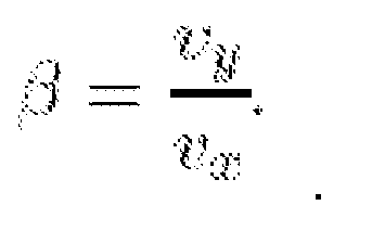
with δ denoting the front steering angle. - In order to avoid possible vehicle instability due to the effects of the tyre nonlinearities, the vehicle is forced to operate in a region of the state space corresponding to limited values of the vehicle body side slip angle β , where β is approximated as
Constraints on the vehicle position are set by the limited lane width. In order to formulate constraints on the vehicle position within a lane, eyij i ∈ {f,r}, j ∈ {l,r} denotes the distances of the four vehicle corners from the lane centreline. By assuming small orientation errors,

where c is the vehicle width and a and b are the distances of the center of gravity from the front and rear vehicle bumpers, respectively. The constraints on the vehicle position are given by:
where eymin and eymax set the maximum allowed deviation from the lane centerline. It should be noted that constraints on the tyre slip angles may also be imposed. - The model equations (5)-(9), along with the constraints given in equations (8) and (10) can be compactly written as:



- The vehicle model equation (11) is used together with a driver model that models a driver's steering behavior as a basis for a threat assessment algorithm.
- According to a further embodiment of the invention for the driver modelling the orientation error

figure 1a ), is defined as:


- The preview signal

- According to an embodiment of the steering angle δ which is output of the driver modelling can be computed from:

where the gains Ky, Kψ are constant and estimated using a least squares method and experimental data. Alternatively the gains Ky , Kψ are time varying and arranged to be updated online. - The driver's steering command computed in equation (13) consists of a linear state feedback term and a feedforward term depending on the desired orientation at the look-ahead point, P, i.e., the preview information. Δψd in equation (12) depends on the preview time tlp that, in the method according to the present invention, is considered as a parameter of the driver's model. Hence Ky and Kψ, tlp can be identified from experimental data.
- The constrained autonomous system, obtained by combining the vehicle model equation (5) and the constraints of equations (8) and (10) with the driver model equation (13), can be compactly written:



- The model equation (14) is discretized with a sampling time T s, to obtain the discrete time constrained autonomous system with disturbances subject to


where, for the sake of simplicity, the state, the disturbance and the time index have been denoted using the same symbols as in equation (14). - The following assumptions on the disturbance signal ωcl have been made.
- Assumption 1:


- Assumption 2. At every time instant t, the disturbance ωcl (t) is known over a finite time horizon of N steps.
- At every time instant t, the second component of the disturbance vector, i.e. Δψd, is based on the desired orientation


- Assumption 2 on the disturbance ωcl requires knowledge of the road geometry over a future time horizon of Nlp steps. Xfeas denotes the set of admissible states and is given by

- At every time instant, a terminal target set T ⊆ X feas is considered. Wt = [wt, wt+1,...,wt+N-1] denotes the sequence of disturbance samples over the time horizon [t,t+N-1] and Wt = [wt, wt+1,...,wt+N-1] denotes any sequence extracted from W t, The sequence of states sets Xt (Wt) =[Xt,X t+1,.....,Xt+N-1 ] is computed from:


- The calculation of the sequence

- In summary, the proposed threat assessment algorithm comprises three main steps to be performed at every time step:
- 1. select a terminal target set, T,
- 2. perform the backward calculation of a sequence of safe sets X t+i according to equation (17) based on the future disturbance sequence Wt , and set T, and
- 3. check whether a current state

vehicle states, Xt , in order to assess the driver's ability in safely driving the vehicle from a current vehicle state to a target set T over the future horizon of N steps. - If the state does not belong to the safe set Xt , an action is required in order to "enlarge" the safe set to enclose the current state. Such an action might be the activation of a driver assistance system.
- It should be noted that the proposed algorithm guarantees a "safe" (i.e., with guarantee of constraints satisfaction) reaching of the target set T. In general, the driver is not guaranteed to keep the vehicle within T after the time t + N.
- The choice of the terminal set Tin the threat assessment algorithm affects the effectiveness and the conservativeness of the algorithm. Indeed, the simplest choice is setting T = X feas. In this case, the algorithm guarantees safe driving only over the future N steps.
- As altemative, the set T may be chosen as T = O∞, where


- It should be noted that further, or fewer parameters may be considered in the vehicle and driver modelling than the examples given in this document.
- The present inventions also concerns a computer program product that comprises a computer program containing computer program code means arranged to cause a computer or a processor to execute the steps of a method according to any of the embodiments of the invention, stored on a computer-readable medium or a carrier wave. The present invention further concerns an electronic control unit (ECU) that comprises such a computer program product and a vehicle that comprises such a computer program product or such an electronic control unit.
- The present invention also concerns the use of set invariance theory for threat assessment in a vehicle.
- The present invention will hereinafter be further explained by means of non-limiting examples with reference to the appended figures where;
- Figure 1 a
- provides a definition of control errors in equation (13),
- Figure 1 b
- provides notation for a single track model,
- Figure 2
- shows validation of the driver model according to an embodiment of the invention, whereby estimated steering angle data is shown on the uppermost graph and validation data is shown on the lowermost graph,
- Figure 3a
- shows a vehicle while negotiating a curve,
- Figure 3b
- shows the safe set at point 1 in
figure 3a , - Figure 3c
- shows the safe set at point 2 in
figure 3a , and - Figure 4
- shows a vehicle according to an embodiment of the present invention.
- It should be noted that the drawings have not been drawn to scale and that the dimensions of certain features have been exaggerated for the sake of clarity.
- The threat assessment algorithm according to the present invention for indicating vehicle instability and/or lane crossing has been experimentally validated on a test track. Full state measurements have been obtained through a differential GPS, a built-in high precision gyro and a digital map. The test track resembled a country road with several sharp curves. In order to assess the algorithm performance in a wide range of operating conditions, the vehicle was driven several laps using both a normal and a slightly rougher driving style, yet without activating any stability system.
- The data used for parameters estimation were collected in normal driving. The problem of estimating the parameters Ky,Kψ and tlp in equation (13) has been formulated as a nonlinear least squares problem since the driver model is linear only in the parameters Ky,Kψ. The data set used for parameters identification is shown in Figure 2(a), while the validation data set is displayed in Figure 2(b). The results in Figure 2(b) show good matching between the driver's steering, predicted by the model equation (13) and measurements.
- The driver model equation (13) has been used to validate, through experimental data, the threat assessment algorithm according to the present invention. A scenario in which the driver is negotiating the curve shown in
Figure 3(a) at a constant speed of 90 km/h has been considered. The vehicle positions 1 and 2 on the track, shown infigure 3(a) have been considered. The time instants when the vehicle is in positions 1 and 2, respectively are denoted by t1 and t2, The dashed lines in figures 2a and 2b starting from the vehicle denote the horizon of N steps, over which the disturbance is assumed to be known. The solid lines is the driver's measured steering angle and the dashed lines are the steering angles predicted using model equation (13). In the two vehicle positions safe sets X t1 and X t2 have been computed, according to the threat assessment algorithm according to the present invention, where set T = X feas is the terminal set and using the following parameters
- In
figures 3b and 3c the polyhedra


- The states


Figures 3(b) and 3(c), respectively. It should be noted

Figures 3(b) and 3(c) with dashed lines. In particular, inFigure 3(b) , starting from the initial state the state trajectory entirely evolves within the set
Figure 3(c) , instead, the state trajectory leaves the
- The present invention therefore concerns a model based threat assessment method for semi-autonomous driving. First a set of constraints is introduced describing "safe" driving. Then, based on the knowledge of the road geometry over a future finite time horizon, the vehicle and driver modeling, set invariance theory is used to calculate a sequence of safe states sets. The validation of the method according to the present invention with experimental results demonstrates that the method effectively predicts a constraints violation, possibly indicating the possibility of an accident or loss of vehicle control.
-
Figure 4 shows avehicle 10 according to an embodiment of the invention. The vehicle comprises anECU 12 comprising a computer program product containing computer program code means arranged to cause a computer or a processor to execute the steps of a method according to any of the embodiments of the invention stored on a computer-readable medium. The vehicle comprises at least onesensor 14 for obtaining information about the surrounding environment, such as a GPS system and/or a camera. Thevehicle 10 also comprises an advanceddriver assistance system 16 which is activated depending on the results of the threat assessment carried out by theECU 12. - Further modifications of the invention within the scope of the claims would be apparent to a skilled person. For example, the method for threat assessment according to the present invention need not necessarily be carried out on board the vehicle but may be carried out at an external location whereby control signals may then be sent to the vehicle to activate a driver assistance system.
Claims (14)
- Method for threat assessment in a vehicle (10), characterized in that it comprises the steps of• introducing a set of constraints on vehicle states which are satisfied under safe driving conditions,• obtaining information about the surrounding environment over a future finite time horizon, and• calculating a sequence of safe vehicle state sets based on vehicle and driver mathematical models using set invariance theory and reachability analysis.
- Method according to claim 1, characterized in that it comprises the step of activating an autonomous intervention if a current vehicle state does not belong to said calculated sequence of safe vehicle state sets.
- Method according to claim 1 or 2, characterized in that in said vehicle modelling the vehicle motion within a lane, subject to lateral and yaw dynamics, is described by the following set of differential equations;


where m and Jz denote the vehicle mass and yaw inertia, respectively, l f and l r are the distances of the vehicle center of gravity from the front and rear axles, respectively, vx and Vy are the longitudinal and lateral velocities, respectively, is the turning rate in the vehicle body frame, where ψ denotes the vehicle orientation with respect to the fixed global frame (X, Y), Fyf , F yr are the lateral tyre forces at the front and rear axles, respectively and where, in (5c) and (5d), eψ and ey denote the vehicle orientation and position errors, respectively, with respect to the road centerline and ψd is the desired vehicle orientation. - Method according to claim 3, characterized in that lateral tyre forces in equations (5a) and (5b) are computed as;

where Ci are the tyre cornering stiffness coefficients at the two axles and αi are the tyre slip angles which, for small values, can be approximated as;

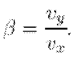
with δ denoting the front steering angle. - Method according to any of the preceding claims, characterized in that said set of constraints on vehicle states which are satisfied under safe driving conditions includes constraints on the vehicle body side slip angle β where β is approximated as
- Method according to any of the preceding claims, characterized in that said set of constraints on vehicle states which are satisfied under safe driving conditions includes constraints on the vehicle position within a lane, whereby the distances of the four vehicle corners from the lane centreline are denoted by:


where c is the vehicle width and a and b are the distances of the center of gravity from the front and rear vehicle bumpers, respectively and where the constraints on the vehicle position are given by:
where eymin and eymax set the maximum allowed deviation from the lane centreline. - Method according to any of the preceding claims, characterized in that in said driver modelling the orientation error


where


- Method according to any of the preceding claims, characterized in that in said driver modelling the steering angle δ is computed from:

where the gains Ky,Kψ are constant and estimated using a least squares method and experimental data. - Method according to any of claims 1-7, characterized in that in said driver modelling the steering angle δ is computed from:

where the gains Ky,Kψ are time varying and arranged to be updated online. - Method according to claim 9, characterized in that it comprises the following steps:• selecting a terminal target set, T,• performing the backward calculation of a sequence of safe sets X t+i based on the future disturbance sequence W t and set T, and• checking whether a current state

safe vehicle states, Xt1 in order to assess the driver's ability in safely driving the vehicle from a current vehicle state to a target set T over the future horizon of N steps. - Computer program product, characterized in that it comprises a computer program containing computer program code means arranged to cause a computer or a processor to execute the steps of a method according to any of claims 1-10, stored on a computer-readable medium or a carrier wave.
- Electronic control unit (ECU) (12), characterized in that it comprises a computer program product according to claim 11.
- Vehicle (10), characterized in that it comprises a computer program product according to claim 11 or an electronic control unit (ECU) (12) according to claim 12.
- Use of the invariance theory for threat assessment in a vehicle (10).
Priority Applications (1)
| Application Number | Priority Date | Filing Date | Title |
|---|---|---|---|
| EP10156390.6A EP2364891B1 (en) | 2010-03-12 | 2010-03-12 | Method for threat assessment in a vehicle |
Applications Claiming Priority (1)
| Application Number | Priority Date | Filing Date | Title |
|---|---|---|---|
| EP10156390.6A EP2364891B1 (en) | 2010-03-12 | 2010-03-12 | Method for threat assessment in a vehicle |
Publications (2)
| Publication Number | Publication Date |
|---|---|
| EP2364891A1 true EP2364891A1 (en) | 2011-09-14 |
| EP2364891B1 EP2364891B1 (en) | 2013-06-19 |
Family
ID=42134390
Family Applications (1)
| Application Number | Title | Priority Date | Filing Date |
|---|---|---|---|
| EP10156390.6A Active EP2364891B1 (en) | 2010-03-12 | 2010-03-12 | Method for threat assessment in a vehicle |
Country Status (1)
| Country | Link |
|---|---|
| EP (1) | EP2364891B1 (en) |
Cited By (1)
| Publication number | Priority date | Publication date | Assignee | Title |
|---|---|---|---|---|
| CN112462764A (en) * | 2020-11-20 | 2021-03-09 | 北京欣奕华科技有限公司 | Construction method and device of vehicle constraint graph |
Families Citing this family (2)
| Publication number | Priority date | Publication date | Assignee | Title |
|---|---|---|---|---|
| DE102021211667A1 (en) | 2021-10-15 | 2023-04-20 | Robert Bosch Gesellschaft mit beschränkter Haftung | Method for providing safe control inputs for actuator components of an automated vehicle |
| DE102021211659A1 (en) | 2021-10-15 | 2023-04-20 | Robert Bosch Gesellschaft mit beschränkter Haftung | Method for providing safe control inputs for actuator components of an automated vehicle |
Citations (6)
| Publication number | Priority date | Publication date | Assignee | Title |
|---|---|---|---|---|
| EP0483905A2 (en) * | 1990-10-29 | 1992-05-06 | Koninklijke Philips Electronics N.V. | Method and apparatus for controlling high speed vehicles |
| US20040186647A1 (en) * | 2003-01-31 | 2004-09-23 | Kabushiki Kaisha Toyota Chuo Kenkyusho | Vehicle control method and vehicle control apparatus |
| DE102007019698A1 (en) * | 2007-04-26 | 2008-10-30 | Ford Global Technologies, LLC, Dearborn | Electrically controlled support of vehicle driving movement involves deriving control parameters for supporting driving movement in mathematical model containing stationary sub-model and dynamic sub-model |
| EP2006181A2 (en) * | 2006-03-22 | 2008-12-24 | Nissan Motor Co., Ltd. | Avoidance operation calculation device, avoidance control device, vehicle with each of the devices, avoidance operation calculation method, and avoidance control method |
| EP2045161A1 (en) * | 2007-10-04 | 2009-04-08 | Deere & Company | Method and system for obstacle avoidance for a vehicle |
| US20090174536A1 (en) * | 2008-01-09 | 2009-07-09 | Rao Manoharprasad K | Accident avoidance during vehicle backup |
-
2010
- 2010-03-12 EP EP10156390.6A patent/EP2364891B1/en active Active
Patent Citations (6)
| Publication number | Priority date | Publication date | Assignee | Title |
|---|---|---|---|---|
| EP0483905A2 (en) * | 1990-10-29 | 1992-05-06 | Koninklijke Philips Electronics N.V. | Method and apparatus for controlling high speed vehicles |
| US20040186647A1 (en) * | 2003-01-31 | 2004-09-23 | Kabushiki Kaisha Toyota Chuo Kenkyusho | Vehicle control method and vehicle control apparatus |
| EP2006181A2 (en) * | 2006-03-22 | 2008-12-24 | Nissan Motor Co., Ltd. | Avoidance operation calculation device, avoidance control device, vehicle with each of the devices, avoidance operation calculation method, and avoidance control method |
| DE102007019698A1 (en) * | 2007-04-26 | 2008-10-30 | Ford Global Technologies, LLC, Dearborn | Electrically controlled support of vehicle driving movement involves deriving control parameters for supporting driving movement in mathematical model containing stationary sub-model and dynamic sub-model |
| EP2045161A1 (en) * | 2007-10-04 | 2009-04-08 | Deere & Company | Method and system for obstacle avoidance for a vehicle |
| US20090174536A1 (en) * | 2008-01-09 | 2009-07-09 | Rao Manoharprasad K | Accident avoidance during vehicle backup |
Cited By (2)
| Publication number | Priority date | Publication date | Assignee | Title |
|---|---|---|---|---|
| CN112462764A (en) * | 2020-11-20 | 2021-03-09 | 北京欣奕华科技有限公司 | Construction method and device of vehicle constraint graph |
| CN112462764B (en) * | 2020-11-20 | 2023-11-24 | 北京欣奕华科技有限公司 | Vehicle constraint graph construction method and device |
Also Published As
| Publication number | Publication date |
|---|---|
| EP2364891B1 (en) | 2013-06-19 |
Similar Documents
| Publication | Publication Date | Title |
|---|---|---|
| US9278713B2 (en) | Collision avoidance control integrated with EPS controller | |
| US9731755B1 (en) | Preview lateral control for automated driving | |
| CN102963358B (en) | The system and method in collision avoidance motor-driven path is determined when having jerking movement degree to limit | |
| EP4301643B1 (en) | Control-envelope based vehicle motion management | |
| CN106094812B (en) | Reaction equation path planning for autonomous driving | |
| US20190389470A1 (en) | System and method for controlling a vehicle based on an anticipated lane departure | |
| US8775006B2 (en) | System and method for enhanced vehicle control | |
| Soualmi et al. | Automation-driver cooperative driving in presence of undetected obstacles | |
| US9645250B2 (en) | Fail operational vehicle speed estimation through data fusion of 6-DOF IMU, GPS, and radar | |
| EP3663153A1 (en) | Vehicle control device | |
| CN114364590B (en) | Device for predictive control of motor vehicle motion | |
| US20200353918A1 (en) | Vehicle control device | |
| US12559128B2 (en) | Systems and methods for updating the parameters of a model predictive controller with learned operational and vehicle parameters generated using simulations and machine learning | |
| CN105539434A (en) | Method of path planning for evasive steering maneuver | |
| US11787404B2 (en) | Systems and methods for personalizing adaptive cruise control in a vehicle | |
| EP3666612A1 (en) | Vehicle control device | |
| US20220355792A1 (en) | Method and device for trajectory planning for a vehicle | |
| Lee et al. | Automated driving control in safe driving envelope based on probabilistic prediction of surrounding vehicle behaviors | |
| EP2364891B1 (en) | Method for threat assessment in a vehicle | |
| Ercan et al. | Torque-based steering assistance for collision avoidance during lane changes | |
| US20210042451A1 (en) | Method for checking a vehicle dynamics model | |
| Hima et al. | Controller design for trajectory tracking of autonomous passenger vehicles | |
| Dahmani et al. | Observer-based tracking control of the vehicle lateral dynamics using four-wheel active steering | |
| Shin et al. | Effects of wireless communication on integrated risk management based automated vehicle | |
| Balachandran et al. | Creating predictive haptic feedback for obstacle avoidance using a model predictive control (MPC) framework |
Legal Events
| Date | Code | Title | Description |
|---|---|---|---|
| PUAI | Public reference made under article 153(3) epc to a published international application that has entered the european phase |
Free format text: ORIGINAL CODE: 0009012 |
|
| AK | Designated contracting states |
Kind code of ref document: A1 Designated state(s): AT BE BG CH CY CZ DE DK EE ES FI FR GB GR HR HU IE IS IT LI LT LU LV MC MK MT NL NO PL PT RO SE SI SK SM TR |
|
| AX | Request for extension of the european patent |
Extension state: AL BA ME RS |
|
| RAP1 | Party data changed (applicant data changed or rights of an application transferred) |
Owner name: VOLVO CAR CORPORATION |
|
| 17P | Request for examination filed |
Effective date: 20120314 |
|
| RIC1 | Information provided on ipc code assigned before grant |
Ipc: B60W 30/08 20120101AFI20120604BHEP Ipc: B60W 40/06 20120101ALI20120604BHEP |
|
| GRAP | Despatch of communication of intention to grant a patent |
Free format text: ORIGINAL CODE: EPIDOSNIGR1 |
|
| GRAP | Despatch of communication of intention to grant a patent |
Free format text: ORIGINAL CODE: EPIDOSNIGR1 |
|
| GRAS | Grant fee paid |
Free format text: ORIGINAL CODE: EPIDOSNIGR3 |
|
| INTG | Intention to grant announced |
Effective date: 20130419 |
|
| GRAA | (expected) grant |
Free format text: ORIGINAL CODE: 0009210 |
|
| AK | Designated contracting states |
Kind code of ref document: B1 Designated state(s): AT BE BG CH CY CZ DE DK EE ES FI FR GB GR HR HU IE IS IT LI LT LU LV MC MK MT NL NO PL PT RO SE SI SK SM TR |
|
| REG | Reference to a national code |
Ref country code: GB Ref legal event code: FG4D |
|
| REG | Reference to a national code |
Ref country code: CH Ref legal event code: EP |
|
| REG | Reference to a national code |
Ref country code: AT Ref legal event code: REF Ref document number: 617474 Country of ref document: AT Kind code of ref document: T Effective date: 20130715 |
|
| REG | Reference to a national code |
Ref country code: IE Ref legal event code: FG4D |
|
| REG | Reference to a national code |
Ref country code: DE Ref legal event code: R096 Ref document number: 602010007847 Country of ref document: DE Effective date: 20130814 |
|
| REG | Reference to a national code |
Ref country code: SE Ref legal event code: TRGR |
|
| PG25 | Lapsed in a contracting state [announced via postgrant information from national office to epo] |
Ref country code: SI Free format text: LAPSE BECAUSE OF FAILURE TO SUBMIT A TRANSLATION OF THE DESCRIPTION OR TO PAY THE FEE WITHIN THE PRESCRIBED TIME-LIMIT Effective date: 20130619 Ref country code: NO Free format text: LAPSE BECAUSE OF FAILURE TO SUBMIT A TRANSLATION OF THE DESCRIPTION OR TO PAY THE FEE WITHIN THE PRESCRIBED TIME-LIMIT Effective date: 20130919 Ref country code: FI Free format text: LAPSE BECAUSE OF FAILURE TO SUBMIT A TRANSLATION OF THE DESCRIPTION OR TO PAY THE FEE WITHIN THE PRESCRIBED TIME-LIMIT Effective date: 20130619 Ref country code: GR Free format text: LAPSE BECAUSE OF FAILURE TO SUBMIT A TRANSLATION OF THE DESCRIPTION OR TO PAY THE FEE WITHIN THE PRESCRIBED TIME-LIMIT Effective date: 20130920 Ref country code: LT Free format text: LAPSE BECAUSE OF FAILURE TO SUBMIT A TRANSLATION OF THE DESCRIPTION OR TO PAY THE FEE WITHIN THE PRESCRIBED TIME-LIMIT Effective date: 20130619 Ref country code: ES Free format text: LAPSE BECAUSE OF FAILURE TO SUBMIT A TRANSLATION OF THE DESCRIPTION OR TO PAY THE FEE WITHIN THE PRESCRIBED TIME-LIMIT Effective date: 20130930 |
|
| REG | Reference to a national code |
Ref country code: AT Ref legal event code: MK05 Ref document number: 617474 Country of ref document: AT Kind code of ref document: T Effective date: 20130619 |
|
| REG | Reference to a national code |
Ref country code: LT Ref legal event code: MG4D |
|
| PG25 | Lapsed in a contracting state [announced via postgrant information from national office to epo] |
Ref country code: HR Free format text: LAPSE BECAUSE OF FAILURE TO SUBMIT A TRANSLATION OF THE DESCRIPTION OR TO PAY THE FEE WITHIN THE PRESCRIBED TIME-LIMIT Effective date: 20130619 Ref country code: BG Free format text: LAPSE BECAUSE OF FAILURE TO SUBMIT A TRANSLATION OF THE DESCRIPTION OR TO PAY THE FEE WITHIN THE PRESCRIBED TIME-LIMIT Effective date: 20130919 |
|
| REG | Reference to a national code |
Ref country code: NL Ref legal event code: VDEP Effective date: 20130619 |
|
| PG25 | Lapsed in a contracting state [announced via postgrant information from national office to epo] |
Ref country code: LV Free format text: LAPSE BECAUSE OF FAILURE TO SUBMIT A TRANSLATION OF THE DESCRIPTION OR TO PAY THE FEE WITHIN THE PRESCRIBED TIME-LIMIT Effective date: 20130619 |
|
| PG25 | Lapsed in a contracting state [announced via postgrant information from national office to epo] |
Ref country code: IS Free format text: LAPSE BECAUSE OF FAILURE TO SUBMIT A TRANSLATION OF THE DESCRIPTION OR TO PAY THE FEE WITHIN THE PRESCRIBED TIME-LIMIT Effective date: 20131019 Ref country code: BE Free format text: LAPSE BECAUSE OF FAILURE TO SUBMIT A TRANSLATION OF THE DESCRIPTION OR TO PAY THE FEE WITHIN THE PRESCRIBED TIME-LIMIT Effective date: 20130619 Ref country code: CZ Free format text: LAPSE BECAUSE OF FAILURE TO SUBMIT A TRANSLATION OF THE DESCRIPTION OR TO PAY THE FEE WITHIN THE PRESCRIBED TIME-LIMIT Effective date: 20130619 Ref country code: AT Free format text: LAPSE BECAUSE OF FAILURE TO SUBMIT A TRANSLATION OF THE DESCRIPTION OR TO PAY THE FEE WITHIN THE PRESCRIBED TIME-LIMIT Effective date: 20130619 Ref country code: SK Free format text: LAPSE BECAUSE OF FAILURE TO SUBMIT A TRANSLATION OF THE DESCRIPTION OR TO PAY THE FEE WITHIN THE PRESCRIBED TIME-LIMIT Effective date: 20130619 Ref country code: PT Free format text: LAPSE BECAUSE OF FAILURE TO SUBMIT A TRANSLATION OF THE DESCRIPTION OR TO PAY THE FEE WITHIN THE PRESCRIBED TIME-LIMIT Effective date: 20131021 Ref country code: EE Free format text: LAPSE BECAUSE OF FAILURE TO SUBMIT A TRANSLATION OF THE DESCRIPTION OR TO PAY THE FEE WITHIN THE PRESCRIBED TIME-LIMIT Effective date: 20130619 Ref country code: CY Free format text: LAPSE BECAUSE OF FAILURE TO SUBMIT A TRANSLATION OF THE DESCRIPTION OR TO PAY THE FEE WITHIN THE PRESCRIBED TIME-LIMIT Effective date: 20130619 |
|
| PG25 | Lapsed in a contracting state [announced via postgrant information from national office to epo] |
Ref country code: NL Free format text: LAPSE BECAUSE OF FAILURE TO SUBMIT A TRANSLATION OF THE DESCRIPTION OR TO PAY THE FEE WITHIN THE PRESCRIBED TIME-LIMIT Effective date: 20130619 Ref country code: PL Free format text: LAPSE BECAUSE OF FAILURE TO SUBMIT A TRANSLATION OF THE DESCRIPTION OR TO PAY THE FEE WITHIN THE PRESCRIBED TIME-LIMIT Effective date: 20130619 Ref country code: RO Free format text: LAPSE BECAUSE OF FAILURE TO SUBMIT A TRANSLATION OF THE DESCRIPTION OR TO PAY THE FEE WITHIN THE PRESCRIBED TIME-LIMIT Effective date: 20130619 |
|
| PLBE | No opposition filed within time limit |
Free format text: ORIGINAL CODE: 0009261 |
|
| STAA | Information on the status of an ep patent application or granted ep patent |
Free format text: STATUS: NO OPPOSITION FILED WITHIN TIME LIMIT |
|
| PG25 | Lapsed in a contracting state [announced via postgrant information from national office to epo] |
Ref country code: DK Free format text: LAPSE BECAUSE OF FAILURE TO SUBMIT A TRANSLATION OF THE DESCRIPTION OR TO PAY THE FEE WITHIN THE PRESCRIBED TIME-LIMIT Effective date: 20130619 |
|
| 26N | No opposition filed |
Effective date: 20140320 |
|
| PG25 | Lapsed in a contracting state [announced via postgrant information from national office to epo] |
Ref country code: IT Free format text: LAPSE BECAUSE OF FAILURE TO SUBMIT A TRANSLATION OF THE DESCRIPTION OR TO PAY THE FEE WITHIN THE PRESCRIBED TIME-LIMIT Effective date: 20130619 |
|
| REG | Reference to a national code |
Ref country code: DE Ref legal event code: R097 Ref document number: 602010007847 Country of ref document: DE Effective date: 20140320 |
|
| PG25 | Lapsed in a contracting state [announced via postgrant information from national office to epo] |
Ref country code: LU Free format text: LAPSE BECAUSE OF FAILURE TO SUBMIT A TRANSLATION OF THE DESCRIPTION OR TO PAY THE FEE WITHIN THE PRESCRIBED TIME-LIMIT Effective date: 20140312 |
|
| REG | Reference to a national code |
Ref country code: CH Ref legal event code: PL |
|
| REG | Reference to a national code |
Ref country code: FR Ref legal event code: ST Effective date: 20141128 |
|
| REG | Reference to a national code |
Ref country code: IE Ref legal event code: MM4A |
|
| PG25 | Lapsed in a contracting state [announced via postgrant information from national office to epo] |
Ref country code: CH Free format text: LAPSE BECAUSE OF NON-PAYMENT OF DUE FEES Effective date: 20140331 Ref country code: LI Free format text: LAPSE BECAUSE OF NON-PAYMENT OF DUE FEES Effective date: 20140331 Ref country code: FR Free format text: LAPSE BECAUSE OF NON-PAYMENT OF DUE FEES Effective date: 20140331 Ref country code: IE Free format text: LAPSE BECAUSE OF NON-PAYMENT OF DUE FEES Effective date: 20140312 |
|
| PG25 | Lapsed in a contracting state [announced via postgrant information from national office to epo] |
Ref country code: MT Free format text: LAPSE BECAUSE OF FAILURE TO SUBMIT A TRANSLATION OF THE DESCRIPTION OR TO PAY THE FEE WITHIN THE PRESCRIBED TIME-LIMIT Effective date: 20130619 |
|
| PG25 | Lapsed in a contracting state [announced via postgrant information from national office to epo] |
Ref country code: SM Free format text: LAPSE BECAUSE OF FAILURE TO SUBMIT A TRANSLATION OF THE DESCRIPTION OR TO PAY THE FEE WITHIN THE PRESCRIBED TIME-LIMIT Effective date: 20130619 |
|
| PG25 | Lapsed in a contracting state [announced via postgrant information from national office to epo] |
Ref country code: MC Free format text: LAPSE BECAUSE OF FAILURE TO SUBMIT A TRANSLATION OF THE DESCRIPTION OR TO PAY THE FEE WITHIN THE PRESCRIBED TIME-LIMIT Effective date: 20130619 |
|
| PG25 | Lapsed in a contracting state [announced via postgrant information from national office to epo] |
Ref country code: TR Free format text: LAPSE BECAUSE OF FAILURE TO SUBMIT A TRANSLATION OF THE DESCRIPTION OR TO PAY THE FEE WITHIN THE PRESCRIBED TIME-LIMIT Effective date: 20130619 Ref country code: HU Free format text: LAPSE BECAUSE OF FAILURE TO SUBMIT A TRANSLATION OF THE DESCRIPTION OR TO PAY THE FEE WITHIN THE PRESCRIBED TIME-LIMIT; INVALID AB INITIO Effective date: 20100312 |
|
| PG25 | Lapsed in a contracting state [announced via postgrant information from national office to epo] |
Ref country code: MK Free format text: LAPSE BECAUSE OF FAILURE TO SUBMIT A TRANSLATION OF THE DESCRIPTION OR TO PAY THE FEE WITHIN THE PRESCRIBED TIME-LIMIT Effective date: 20130619 |
|
| PGFP | Annual fee paid to national office [announced via postgrant information from national office to epo] |
Ref country code: SE Payment date: 20200210 Year of fee payment: 11 |
|
| PG25 | Lapsed in a contracting state [announced via postgrant information from national office to epo] |
Ref country code: SE Free format text: LAPSE BECAUSE OF NON-PAYMENT OF DUE FEES Effective date: 20210313 |
|
| P01 | Opt-out of the competence of the unified patent court (upc) registered |
Effective date: 20231212 |
|
| PGFP | Annual fee paid to national office [announced via postgrant information from national office to epo] |
Ref country code: GB Payment date: 20240220 Year of fee payment: 15 |
|
| PGFP | Annual fee paid to national office [announced via postgrant information from national office to epo] |
Ref country code: DE Payment date: 20250218 Year of fee payment: 16 |
|
| GBPC | Gb: european patent ceased through non-payment of renewal fee |
Effective date: 20250312 |
|
| PG25 | Lapsed in a contracting state [announced via postgrant information from national office to epo] |
Ref country code: GB Free format text: LAPSE BECAUSE OF NON-PAYMENT OF DUE FEES Effective date: 20250312 |