EP2364879A1 - Ladder clamping structure for ladder racks - Google Patents
Ladder clamping structure for ladder racks Download PDFInfo
- Publication number
- EP2364879A1 EP2364879A1 EP11250266A EP11250266A EP2364879A1 EP 2364879 A1 EP2364879 A1 EP 2364879A1 EP 11250266 A EP11250266 A EP 11250266A EP 11250266 A EP11250266 A EP 11250266A EP 2364879 A1 EP2364879 A1 EP 2364879A1
- Authority
- EP
- European Patent Office
- Prior art keywords
- ladder
- hook member
- crossbars
- hook
- clamped
- Prior art date
- Legal status (The legal status is an assumption and is not a legal conclusion. Google has not performed a legal analysis and makes no representation as to the accuracy of the status listed.)
- Granted
Links
- 238000001125 extrusion Methods 0.000 claims abstract description 12
- 229910052751 metal Inorganic materials 0.000 claims description 2
- 239000002184 metal Substances 0.000 claims description 2
- 229910052782 aluminium Inorganic materials 0.000 abstract description 3
- XAGFODPZIPBFFR-UHFFFAOYSA-N aluminium Chemical compound [Al] XAGFODPZIPBFFR-UHFFFAOYSA-N 0.000 abstract description 3
- 230000007246 mechanism Effects 0.000 abstract description 3
- 238000009877 rendering Methods 0.000 abstract 1
- 238000003466 welding Methods 0.000 abstract 1
- 239000007789 gas Substances 0.000 description 12
- IJGRMHOSHXDMSA-UHFFFAOYSA-N Atomic nitrogen Chemical compound N#N IJGRMHOSHXDMSA-UHFFFAOYSA-N 0.000 description 2
- 230000001133 acceleration Effects 0.000 description 2
- 230000000712 assembly Effects 0.000 description 2
- 238000000429 assembly Methods 0.000 description 2
- 238000005452 bending Methods 0.000 description 1
- 230000006835 compression Effects 0.000 description 1
- 238000007906 compression Methods 0.000 description 1
- 238000010276 construction Methods 0.000 description 1
- 230000006378 damage Effects 0.000 description 1
- 238000013016 damping Methods 0.000 description 1
- 230000001050 lubricating effect Effects 0.000 description 1
- 238000000034 method Methods 0.000 description 1
- 238000012986 modification Methods 0.000 description 1
- 230000004048 modification Effects 0.000 description 1
- 229910052757 nitrogen Inorganic materials 0.000 description 1
- 238000011017 operating method Methods 0.000 description 1
- 230000000284 resting effect Effects 0.000 description 1
Images


Classifications
-
- B—PERFORMING OPERATIONS; TRANSPORTING
- B60—VEHICLES IN GENERAL
- B60R—VEHICLES, VEHICLE FITTINGS, OR VEHICLE PARTS, NOT OTHERWISE PROVIDED FOR
- B60R9/00—Supplementary fittings on vehicle exterior for carrying loads, e.g. luggage, sports gear or the like
- B60R9/04—Carriers associated with vehicle roof
- B60R9/048—Carriers characterised by article-gripping, -covering,-retaining, or -locking means
- B60R9/0485—Carriers characterised by article-gripping, -covering,-retaining, or -locking means for ladders
Definitions
- these prior art ladder rack assemblies are of a welded configuration having longitudinally extending side rails attached to transversely extending crossbar members by a welded connection, which limits the ability for a given design to be used on different van vehicle models because of the inability to adjust the welded configuration.
- a pair of longitudinally extending side rails are held in parallel, spaced-apart relation by crossbar members extending therebetween and welded to the side rails.
- the roof rack and associated ladder clamping device of the present invention is fabricated from lightweight aluminum extrusions without the need for any welds.
- racks can be packaged and shipped in a relatively small carton and assembled by the user using a single tool, namely, a socket wrench with a one-half inch socket. Because of the design of the extrusions employed for the side rails and crossbar members of the roof rack, even though the assembled rack is light in weight, it remains very rigid and able to support heavy loads without bending.
- the present invention is directed to a ladder clamping assembly for a vehicle roof rack
- the roof rack includes a pair of spaced-apart, longitudinally extending side rails held in parallel relationship by a plurality of transversely extending crossbars that are clamped to the pair of side rails at opposed ends of the crossbars.
- Both the side rails and the crossbars comprise metal extrusions having clamping ridges extending along the length dimension thereof.
- the ladder rack may include one or more ladder clamping assemblies.
- the ladder clamping assembly itself comprises an elongated hook bar that extends between and is clamped to the clamping ridges of adjacent ones of the plurality of crossbars.
- the hook bar supports a front hook member that is longitudinally positionable along the length dimension of the hook bar and is adapted to engage an upper ladder rung of a ladder when being carried on the vehicle roof rack to prevent forward movement of a ladder.
- the ladder clamping assembly further comprises first and second bearing brackets that support a cylindrical rod and where the first and second bearing brackets are clamped to the clamping ridges of a common one of the plurality of crossbar members for journaling the cylindrical rod for rotation about an axis that is parallel to the crossbar members.
- a rear hook member is keyed to and clamped on the cylindrical rod at a location that is aligned with the hook bar and a crank arm is clamped to the cylindrical rod whereby manual rotation of the crank arm is adapted to bring the rear hook member into engagement with a lower ladder rung to prevent rearward movement of a ladder when being carried by the roof rack.
- a vehicle roof rack with ladder clamping devices of the present invention incorporated is indicated generally by numeral 10. It is seen to comprise a pair of tubular side rails 12 and 14 of extruded aluminum that are held in parallel, spaced-apart relationship to one another by a plurality of crossbars 16 and 18. The manner in which the crossbars attach to the side rails will be discussed later with the aid of Figure 2 , but for now, it is suffice to say that these parts are clamped to one another rather than being welded as in most prior art roof racks. Extending along the length dimension of the tubular side rails 12 and 14 is a clamping ridge 23 ( Figure 2 ) formed by the extrusion die to resemble an inverted T.
- FIG 2 shows the manner in which the rear crossbar 18 is clamped and held to the right side rail member 12, taking advantage of clamping ridges formed on both the crossbar 18 and the side rail 12.
- an L-shaped support bracket 25 is clamped to a clamping ridge 23 of the extruded side rail 12 using a clamping plate 21 1 where the clamping plate 21 and support bracket 25 are held together by a screw and bolts 27 and 27'.
- the left end of the crossbar 18 is then made to rest on the L-bracket 25 and then bearing bracket 40 and wedge plate 31 are made to engage the clamping ridges 47 and 49 of the crossbar 18 shown best in Figure 6 .
- a shoulder bolt 33 is then inserted through the bearing bracket 40 and wedge plate 31 and a washer and 1 ⁇ 2" aircraft nut 35 are screwed onto the bolt 33 and tightened to move the wedge plate to the right and thereby rigidly clamp the left end of the crossbar 18 to the side rail 12.
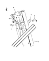
- tubular horn members 37 and 39 Attached to the front end of the side rails 12 and 14 are tubular horn members 37 and 39 comprising tubing that has been formed into an arcuate curve so as to extend upwardly and outwardly relative to the side rails to which they are attached.
- the horn members may lie in a plane that is about 30° to the vertical. Details of the attachment method can be seen in Figure 4 where a proximal end of the tubular horn 37 fits into a tubular clamp 41 that is designed to slip over the forward end of the side rail 12 and secured to the clamping ridge thereof upon tightening of the nuts 43.
- hook bar extrusions 20 that supports front hook members 22 thereon.
- the front hook members each comprise a right angled bracket 24 having its base 26 affixed to the hook bar 20 so as to be adjustable therealong and when at a desired position is firmly held in place by snuggling down a pair of bolts 28 that fit into T-nuts 32 ( Figure 4 ).
- FIG 3 is an end view of the hook bar extrusions 20 and it can be seen that they incorporate a T-slot 30 in a top portion thereof into which T-nuts 32 are fitted, as shown in Figure 4 .
- the front hook member 22 can be slid longitudinally with the T-nuts riding in the T-slot 30.
- the bolts 28 are tightened to lock the front hook member 22 in place.
- the hook bar extrusions 20 also include clamping ridges 46 and 48 running the length thereof.
- the vertical leg of the right-angled bracket 24 has a longitudinal slot formed therein.
- Bolts (not shown) passing through the apertures 34 can ride up or down in that slot to allow adjustment the height of the hook 22 relative to the hook bar 20 and by tightening those bolts the selected height setting is maintained.
- FIG. 5 A perspective view of a rear clamp assembly detached from the roof rack is illustrated in Figure 5 . Shown in Figure 5 is the first bearing bracket 38 and a second bearing bracket 40 used to support a cylindrical rod 42.
- the bearing bracket 38 is adapted to be clamped to the crossbar 18 as previously explained with the inwardly turned end portion 54 thereof engaging a clamping ridge 49 formed on the crossbar extrusion 18 as seen in Figure 6 .
- a further clamping ridge 47 becomes engaged by wedge plate 58 and when the nut 56 is tightened, the wedge plate is camed to the right, causing the bracket 38 to become rigidly secured to the crossbar 18.
- the bearing bracket 40 is likewise secured to the crossbar 18 when the barb-like protuberance 44 engages the clamping ridge 49 and the nut 52 is tightened to move the wedge plate 50 into engagement with the clamping ridge 47 of the crossbar 18.
- the cylindrical shaft 42 supports a rear hook member 60 thereon. More particularly, as seen in Figure 5 , the rear hook member 60 is secured to a leg 62 that is bolted to a cylindrical hub 63 through which the cylindrical shaft 42 is made to pass. While not visible in Figure 5 , projecting radially inward from the I.D. of the hub 63 is a key that is adapted to fit within a keyway 66 milled or otherwise formed in the surface of the cylindrical shaft 42. Thus, the hub 63 and the attached rear hook member 60 can be positioned axially along the length of the shaft 42 allowing the rear hook member to be aligned with the front hook member along the length of the hook bar 20.
- a gas spring 68 is operatively coupled between a rod clamping bracket 64 keyed to the shaft 42 and the bearing bracket 40. More particularly, the gas spring 68 has its cylinder segment bolted by a bolt 70 to the free end of leg 29 of bearing bracket 38 and its piston rod is secured by a bolt 72 to an extension 74 of the rod clamping bracket 38.
- the gas-filled spring consists of a precision rod attached to a piston moving within a sealed cylinder containing nitrogen at high pressure. Output forces are the result of the differential between the pressure in the cylinder and atmospheric pressure outside the cylinder acting on the cross section of the rod. As the piston rod is introduced into the cylinder (compression stroke), the internal pressure increases according to the volume of gas displaced by the rod.
- gas springs are almost constant force. All gas springs contain a small amount of oil to lubricate the main seal and rod and provide end of stroke damping. Hence, the gas spring is preferably mounted with its rod inclined downward off horizontal. This allows the oil to reach the main seal, lubricating it and extending the life of the gas spring.
- the gas spring functions to urge the rear hook member 60 into engagement with a ladder rung thereby capturing the ladder between the front hook member 22 and the rear hook member 60.
- Manual rotation of the crank arm 80 in the clockwise direction when viewed in Figure 1 is required to overcome the force exerted by the gas spring when it is desired to release and remove a ladder from the roof rack.
- the amount of torque applied to the cylindrical rod 42 by manual actuation of the handle 82 must far exceed any force against the rear stop member 60 by the ladder load upon rapid acceleration of the work vehicle.
- the crank arm 80 is clamped to the left end of the cylindrical rod 42 ( Figure 5 ). Formed through the crank arm is an aperture 84. Clamped onto a clamping ridge 23 formed along the length dimension of the side rail 12 is a lock bracket 86 ( Figure 6 ) that also has an aperture extending through its thickness dimension. When the rear hook member 60 is in its raised, ladder rung-engaging disposition, the aperture 84 in the handle 80 becomes aligned with the aperture in the lock plate 86. This allows the shackle of a padlock (not shown) to be passed through the aligned apertures and thereby lock the assembly, preventing removal of a stowed ladder.
- the present invention provides an improved mechanism for releasably securing ladders to a roof rack of a work vehicle that will safely hold such ladders in place during transit, but allowing the ladders to be quickly disengaged for removal and reloading from and to a roof rack when at the worksite.
- crank in a counterclockwise direction functions to overcome the force of the gas spring and rotation of the rear hook member from its ladder rung-engaging state to a position where the rear hook member is generally horizontal and out of the way of the ladder rungs, allowing the operator, while standing on the ground, to lift the ladder over the horizontal portion of the adjacent side rail and have the lower end of the ladder reach the ground while the upper end of the ladder remains resting against the curved horn member.
- the operator may then reposition himself or herself and grasp the ladder at its balance point and carry it to the location where it is to be used.
- a ladder onto the rack In reloading a ladder onto the rack, it is carried in a generally vertical orientation alongside the vehicle and one side of the ladder is brought to rest against the curved and outwardly angled horn. The operator then lifts the rear end of the ladder and swings it over the adjacent side rail such that the ladder is now lying flat on the roof rack and is pushed forward until a leading rung proximate the top end of the ladder is brought into contact with the front hook member 22. Next, the crank handle 82 is rotated in a counterclockwise direction when viewed as in the accompanying drawings to thereby elevate the rear hook member and bring it into engagement with a different ladder rung such that the ladder is effectively trapped between the front and rear hook members.
- the gas spring 68 affords sufficient resistance against clockwise rotation of the rear hook member due to sudden acceleration of the vehicle, thereby preventing shifting of the ladder load.
Landscapes
- Engineering & Computer Science (AREA)
- Mechanical Engineering (AREA)
- Ladders (AREA)
- Fittings On The Vehicle Exterior For Carrying Loads, And Devices For Holding Or Mounting Articles (AREA)
Abstract
Description
-
- I. Field of the Invention: This invention relates generally to roof or ladder racks mountable on the roof of motor vehicles for transporting one or more extension ladders and/or step ladders to a worksite, and more particularly to a roof rack with an improved clamp arrangement for securing such ladder loads onto the roof rack to prevent the loss of the ladder load during transport thereof.
- II. Discussion of the Prior Art: Work vehicles, such as commercial vans, often incorporate a roof rack adapted to support cargo of one type or another to be used at a worksite. Such cargo often includes extension ladders and/or stepladders. To avoid loss of the cargo during transport and possible serious injuries to other motorists who may be traveling behind the work vehicle, various means have been devised for securing cargo, and especially ladders, to the ladder rack. For example, some have used bungee cords and ropes to tie ladders in place on the vehicle-mounted roof rack, but this is generally a considerable effort, especially given the height and placement of the ladder rack on the van roof.
- Various other mechanisms have been devised for latching ladders onto a ladder rack and the below-listed patents represent illustrative efforts of other inventors to secure ladders in place.
Falastich 4,170,331 Nutt 4,262,834 Weger, Jr. 4,618,083 Nutt 4,813,585 Sutton et al. 5,186,588 Finley 5,242,094 McLellan 5,603,591 Pyler 6,290,113 - For the most part, these prior art ladder rack assemblies are of a welded configuration having longitudinally extending side rails attached to transversely extending crossbar members by a welded connection, which limits the ability for a given design to be used on different van vehicle models because of the inability to adjust the welded configuration. In most prior art ladder racks, a pair of longitudinally extending side rails are held in parallel, spaced-apart relation by crossbar members extending therebetween and welded to the side rails.
- In contrast to what is described in the above-cited prior art, the roof rack and associated ladder clamping device of the present invention is fabricated from lightweight aluminum extrusions without the need for any welds. As such, racks can be packaged and shipped in a relatively small carton and assembled by the user using a single tool, namely, a socket wrench with a one-half inch socket. Because of the design of the extrusions employed for the side rails and crossbar members of the roof rack, even though the assembled rack is light in weight, it remains very rigid and able to support heavy loads without bending.
- The present invention is directed to a ladder clamping assembly for a vehicle roof rack where the roof rack includes a pair of spaced-apart, longitudinally extending side rails held in parallel relationship by a plurality of transversely extending crossbars that are clamped to the pair of side rails at opposed ends of the crossbars. Both the side rails and the crossbars comprise metal extrusions having clamping ridges extending along the length dimension thereof.
- The ladder rack may include one or more ladder clamping assemblies. The ladder clamping assembly itself comprises an elongated hook bar that extends between and is clamped to the clamping ridges of adjacent ones of the plurality of crossbars. The hook bar supports a front hook member that is longitudinally positionable along the length dimension of the hook bar and is adapted to engage an upper ladder rung of a ladder when being carried on the vehicle roof rack to prevent forward movement of a ladder.
- The ladder clamping assembly further comprises first and second bearing brackets that support a cylindrical rod and where the first and second bearing brackets are clamped to the clamping ridges of a common one of the plurality of crossbar members for journaling the cylindrical rod for rotation about an axis that is parallel to the crossbar members. A rear hook member is keyed to and clamped on the cylindrical rod at a location that is aligned with the hook bar and a crank arm is clamped to the cylindrical rod whereby manual rotation of the crank arm is adapted to bring the rear hook member into engagement with a lower ladder rung to prevent rearward movement of a ladder when being carried by the roof rack.
- Further features, objects and advantages of the invention will become apparent to those skilled in the art from the following detailed description of a preferred embodiment, especially when considered in conjunction with the accompanying drawings in which like numerals in the several views refer to corresponding parts.
-
-
Figure 1 is a perspective view of a roof rack incorporating a ladder clamping assembly in accordance with the present invention; -
Figure 2 is an enlarged detailed drawing showing the manner in which a crossbar of the roof rack attaches to its side rail; -
Figure 3 is an end view of the extrusion comprising the hook bar; -
Figure 4 is an exploded detailed view illustrating the assembly of the hook bar to a crossbar of the roof rack and the attachment of a front horn tube to a side rail; -
Figure 5 is a perspective view of a rear clamp assembly; -
Figure 6 is an exploded view illustrating how the rear clamp assembly attaches to a rear crossbar; and -
Figure 7 is a detailed view showing the rear clamp assembly assembled to the rear crossbar of the roof rack. - This description of the preferred embodiments is intended to be read in connection with the accompanying drawings, which are to be considered part of the entire written description of this invention. In the description, relative terms such as "lower", "upper", "horizontal", "vertical", "above", "below", "up", "down", "top" and "bottom" as well as derivatives thereof (e.g., "horizontally", "downwardly", "upwardly", etc.) should be construed to refer to the orientation as then described or as shown in the drawings under discussion. These relative terms are for convenience of description and do not require that the apparatus be constructed or operated in a particular orientation. Terms such as "connected", "connecting", "attached", "attaching", "join" and "joining" are used interchangeably and refer to one structure or surface being secured to another structure or surface or integrally fabricated in one piece, unless expressively described otherwise.
- Referring first to
Figure 1 , a vehicle roof rack with ladder clamping devices of the present invention incorporated is indicated generally bynumeral 10. It is seen to comprise a pair of tubular side rails 12 and 14 of extruded aluminum that are held in parallel, spaced-apart relationship to one another by a plurality ofcrossbars Figure 2 , but for now, it is suffice to say that these parts are clamped to one another rather than being welded as in most prior art roof racks. Extending along the length dimension of the tubular side rails 12 and 14 is a clamping ridge 23 (Figure 2 ) formed by the extrusion die to resemble an inverted T. -
Figure 2 shows the manner in which therear crossbar 18 is clamped and held to the rightside rail member 12, taking advantage of clamping ridges formed on both thecrossbar 18 and theside rail 12. As a first step, an L-shapedsupport bracket 25 is clamped to a clampingridge 23 of the extrudedside rail 12 using aclamping plate 21 1 where the clampingplate 21 andsupport bracket 25 are held together by a screw andbolts 27 and 27'. The left end of thecrossbar 18 is then made to rest on the L-bracket 25 and then bearingbracket 40 andwedge plate 31 are made to engage the clampingridges crossbar 18 shown best inFigure 6 . Ashoulder bolt 33 is then inserted through the bearingbracket 40 andwedge plate 31 and a washer and ½"aircraft nut 35 are screwed onto thebolt 33 and tightened to move the wedge plate to the right and thereby rigidly clamp the left end of thecrossbar 18 to theside rail 12. - Attached to the front end of the side rails 12 and 14 are
tubular horn members Figure 4 where a proximal end of thetubular horn 37 fits into atubular clamp 41 that is designed to slip over the forward end of theside rail 12 and secured to the clamping ridge thereof upon tightening of the nuts 43. - With reference to
Figures 1 and4 , extending between and clamped onto thecrossbars front hook members 22 thereon. The front hook members each comprise a rightangled bracket 24 having its base 26 affixed to thehook bar 20 so as to be adjustable therealong and when at a desired position is firmly held in place by snuggling down a pair ofbolts 28 that fit into T-nuts 32 (Figure 4 ). -
Figure 3 is an end view of thehook bar extrusions 20 and it can be seen that they incorporate a T-slot 30 in a top portion thereof into which T-nuts 32 are fitted, as shown inFigure 4 . It will be appreciated that when thebolts 28 are loose, thefront hook member 22 can be slid longitudinally with the T-nuts riding in the T-slot 30. When in a desired location that will engage a rung of a ladder to be transported, thebolts 28 are tightened to lock thefront hook member 22 in place. The hook bar extrusions 20 also include clampingridges - While not visible in
Figure 1 , the vertical leg of the right-angledbracket 24 has a longitudinal slot formed therein. Bolts (not shown) passing through theapertures 34 can ride up or down in that slot to allow adjustment the height of thehook 22 relative to thehook bar 20 and by tightening those bolts the selected height setting is maintained. - Clamped to the
rearmost crossbar 18 is a rear clamp assembly indicated generally bynumeral 36. Since they are identical in construction, only one assembly needs to be described. A perspective view of a rear clamp assembly detached from the roof rack is illustrated inFigure 5 . Shown inFigure 5 is thefirst bearing bracket 38 and asecond bearing bracket 40 used to support acylindrical rod 42. The bearingbracket 38 is adapted to be clamped to thecrossbar 18 as previously explained with the inwardly turnedend portion 54 thereof engaging a clampingridge 49 formed on thecrossbar extrusion 18 as seen inFigure 6 . A further clampingridge 47 becomes engaged bywedge plate 58 and when thenut 56 is tightened, the wedge plate is camed to the right, causing thebracket 38 to become rigidly secured to thecrossbar 18. The bearingbracket 40 is likewise secured to thecrossbar 18 when the barb-like protuberance 44 engages the clampingridge 49 and thenut 52 is tightened to move thewedge plate 50 into engagement with the clampingridge 47 of thecrossbar 18. - The
cylindrical shaft 42 supports arear hook member 60 thereon. More particularly, as seen inFigure 5 , therear hook member 60 is secured to aleg 62 that is bolted to acylindrical hub 63 through which thecylindrical shaft 42 is made to pass. While not visible inFigure 5 , projecting radially inward from the I.D. of thehub 63 is a key that is adapted to fit within akeyway 66 milled or otherwise formed in the surface of thecylindrical shaft 42. Thus, thehub 63 and the attachedrear hook member 60 can be positioned axially along the length of theshaft 42 allowing the rear hook member to be aligned with the front hook member along the length of thehook bar 20. - As further seen in
Figure 5 , agas spring 68 is operatively coupled between arod clamping bracket 64 keyed to theshaft 42 and the bearingbracket 40. More particularly, thegas spring 68 has its cylinder segment bolted by abolt 70 to the free end ofleg 29 of bearingbracket 38 and its piston rod is secured by abolt 72 to anextension 74 of therod clamping bracket 38. The gas-filled spring consists of a precision rod attached to a piston moving within a sealed cylinder containing nitrogen at high pressure. Output forces are the result of the differential between the pressure in the cylinder and atmospheric pressure outside the cylinder acting on the cross section of the rod. As the piston rod is introduced into the cylinder (compression stroke), the internal pressure increases according to the volume of gas displaced by the rod. This increase in force is typically between 5% and 50%. In comparison to mechanical springs, gas springs are almost constant force. All gas springs contain a small amount of oil to lubricate the main seal and rod and provide end of stroke damping. Hence, the gas spring is preferably mounted with its rod inclined downward off horizontal. This allows the oil to reach the main seal, lubricating it and extending the life of the gas spring. - In the present application, the gas spring functions to urge the
rear hook member 60 into engagement with a ladder rung thereby capturing the ladder between thefront hook member 22 and therear hook member 60. Manual rotation of thecrank arm 80 in the clockwise direction when viewed inFigure 1 is required to overcome the force exerted by the gas spring when it is desired to release and remove a ladder from the roof rack. The amount of torque applied to thecylindrical rod 42 by manual actuation of thehandle 82 must far exceed any force against therear stop member 60 by the ladder load upon rapid acceleration of the work vehicle. - The
crank arm 80 is clamped to the left end of the cylindrical rod 42 (Figure 5 ). Formed through the crank arm is anaperture 84. Clamped onto a clampingridge 23 formed along the length dimension of theside rail 12 is a lock bracket 86 (Figure 6 ) that also has an aperture extending through its thickness dimension. When therear hook member 60 is in its raised, ladder rung-engaging disposition, theaperture 84 in thehandle 80 becomes aligned with the aperture in thelock plate 86. This allows the shackle of a padlock (not shown) to be passed through the aligned apertures and thereby lock the assembly, preventing removal of a stowed ladder. - From what has been described, those skilled in the art will appreciate that the present invention provides an improved mechanism for releasably securing ladders to a roof rack of a work vehicle that will safely hold such ladders in place during transit, but allowing the ladders to be quickly disengaged for removal and reloading from and to a roof rack when at the worksite. Turning of the crank in a counterclockwise direction functions to overcome the force of the gas spring and rotation of the rear hook member from its ladder rung-engaging state to a position where the rear hook member is generally horizontal and out of the way of the ladder rungs, allowing the operator, while standing on the ground, to lift the ladder over the horizontal portion of the adjacent side rail and have the lower end of the ladder reach the ground while the upper end of the ladder remains resting against the curved horn member. The operator may then reposition himself or herself and grasp the ladder at its balance point and carry it to the location where it is to be used.
- In reloading a ladder onto the rack, it is carried in a generally vertical orientation alongside the vehicle and one side of the ladder is brought to rest against the curved and outwardly angled horn. The operator then lifts the rear end of the ladder and swings it over the adjacent side rail such that the ladder is now lying flat on the roof rack and is pushed forward until a leading rung proximate the top end of the ladder is brought into contact with the
front hook member 22. Next, the crank handle 82 is rotated in a counterclockwise direction when viewed as in the accompanying drawings to thereby elevate the rear hook member and bring it into engagement with a different ladder rung such that the ladder is effectively trapped between the front and rear hook members. It can be locked for security purposes by using a padlock securing thehandle 84 to thelock bracket 86 as previously described. Even without such a padlock arrangement, thegas spring 68 affords sufficient resistance against clockwise rotation of the rear hook member due to sudden acceleration of the vehicle, thereby preventing shifting of the ladder load. - This invention has been described herein in considerable detail in order to comply with the patent statutes and to provide those skilled in the art with the information needed to apply the novel principles and to construct and use such specialized components as are required. However, it is to be understood that the invention can be carried out by specifically different equipment and devices, and that various modifications, both as to the equipment and operating procedures, can be accomplished without departing from the scope of the invention itself.
Claims (7)
- A ladder clamping assembly for a vehicle ladder rack where said vehicle ladder rack includes a pair of spaced-apart, longitudinally extending side rails held in parallel relationship by a plurality of transversely extending crossbars clamped to said pair of side rails at opposed ends of said crossbars, each of said side rails and said crossbars comprising metal extrusions having clamping ridges extending along the length dimensions thereof where the ladder clamping assembly comprises:(a) an elongate hook bar extending between and clamped to said clamping ridges of adjacent ones of said plurality of crossbars, said hook bar supporting a front hook member adapted to engage a ladder rung of a ladder when being carried on said vehicle ladder rack to prevent forward movement of a ladder;(b) first and second bearing brackets supporting a cylindrical rod and where said first and second bearing brackets are clamped to the clamping ridges of a common one of the plurality of crossbar members for journaling the cylindrical rod for rotation about an axis that is parallel to said crossbar members;(c) a rear hook member keyed to and clamped on the cylindrical rod at a location aligned with the hook bar; and(d) a crank arm clamped to the cylindrical rod whereby manual rotation of the crank arm is adapted to bring the rear hook member into engagement with a ladder rung, other than the first ladder rung, to prevent rearward movement of a ladder when being carried by said ladder rack.
- The ladder clamping assembly as in claim 1 and further including a gas spring operatively disposed between one of said first and second bearing brackets and a rod bracket keyed to the cylindrical rod for resiliently holding the rear hook member in ladder rung engagement.
- The ladder clamping assembly as in claim 1 wherein the length of the rear hook member is adjustable.
- The ladder clamping assembly as in claim 1 wherein the length of the front hook member is adjustable.
- The ladder clamping assembly as in claim 1 wherein the front hook member is longitudinally positionable along the length dimension of the hook bar.
- The ladder clamping assembly as in claim 1 and further including at least one aperture formed through the crank arm and a locking bracket clamped to one of the pair of side rails and having an aperture therethrough that becomes aligned with the at least one aperture formed through the crank arm when the crank arm has been rotated to bring the rear hook member into engagement with said ladder rung, other than said first ladder rung, such that a shackle of a padlock can be made to pass through the aligned apertures.
- The ladder clamping assembly as in claim 1 wherein the hook bar comprises an elongate extrusion having a T-slot channel formed in a top surface thereof and the front hook member is positionable along the T-slot channel and fixedly attached to the hook bar by a screw passing through an aperture in the hook member and into a nut captured in the T-slot channel.
Applications Claiming Priority (1)
| Application Number | Priority Date | Filing Date | Title |
|---|---|---|---|
| US12/719,573 US20110214944A1 (en) | 2010-03-08 | 2010-03-08 | Ladder Clamping Structure for Ladder Racks |
Publications (2)
| Publication Number | Publication Date |
|---|---|
| EP2364879A1 true EP2364879A1 (en) | 2011-09-14 |
| EP2364879B1 EP2364879B1 (en) | 2013-07-31 |
Family
ID=44114366
Family Applications (1)
| Application Number | Title | Priority Date | Filing Date |
|---|---|---|---|
| EP11250266.1A Not-in-force EP2364879B1 (en) | 2010-03-08 | 2011-03-08 | Ladder clamping structure for ladder racks |
Country Status (2)
| Country | Link |
|---|---|
| US (1) | US20110214944A1 (en) |
| EP (1) | EP2364879B1 (en) |
Families Citing this family (14)
| Publication number | Priority date | Publication date | Assignee | Title |
|---|---|---|---|---|
| WO2009140496A2 (en) * | 2008-05-14 | 2009-11-19 | Frank Elezaj | Vehicle roof storage system |
| WO2012122130A2 (en) * | 2011-03-04 | 2012-09-13 | Adrian Steel Company | Ladder rack system |
| US8511525B1 (en) | 2012-02-06 | 2013-08-20 | Avraham Y. Levi | Roller guide for vehicle roof mounted ladder rack |
| WO2014018283A1 (en) * | 2012-07-23 | 2014-01-30 | Levi Avraham Y | Ladder clamping apparatus for vehicle roof rack |
| KR101439157B1 (en) | 2013-09-26 | 2014-09-11 | 현대자동차주식회사 | Mounting structure of bearing-bracket |
| CN103628811B (en) * | 2013-11-22 | 2015-04-15 | 四川森田消防装备制造有限公司 | Lateral arc-shaped hanging ladder of fire fighting truck |
| US9481313B2 (en) | 2014-11-17 | 2016-11-01 | Safe Fleet Acquisition Corporation | Ergonomic ladder rack for work vans |
| US9233647B1 (en) * | 2015-06-26 | 2016-01-12 | Dejana Truck & Utility | Shelving system with a ladder cage |
| AU2016340033B2 (en) * | 2015-10-14 | 2021-09-02 | Kracarak Pty Ltd | Holding apparatus |
| US11454064B1 (en) * | 2018-02-26 | 2022-09-27 | Sean D. Campbell | Step ladder carrier |
| CN109131116A (en) * | 2018-10-10 | 2019-01-04 | 安徽省华晟塑胶股份有限公司 | A kind of safe handling automobile luggage racks |
| US11254266B2 (en) | 2019-04-17 | 2022-02-22 | Elias Meza Meza | Ladder transport system |
| CA3160857A1 (en) * | 2021-05-28 | 2022-11-28 | Ranger Design | Ladder rack assembly |
| US12397717B2 (en) | 2022-02-07 | 2025-08-26 | Adrian Steel Company | Ladder rack with reducible width and/or height |
Citations (3)
| Publication number | Priority date | Publication date | Assignee | Title |
|---|---|---|---|---|
| US3722766A (en) * | 1971-02-12 | 1973-03-27 | Southern Cross Ind Inc | Ladder rack |
| FR2632040A1 (en) * | 1988-05-30 | 1989-12-01 | Caetano Bosq Sarl | Ladder-locking device for a ladder rack mounted on a utility or other vehicle |
| WO2009140496A2 (en) * | 2008-05-14 | 2009-11-19 | Frank Elezaj | Vehicle roof storage system |
Family Cites Families (20)
| Publication number | Priority date | Publication date | Assignee | Title |
|---|---|---|---|---|
| US3904094A (en) * | 1973-09-06 | 1975-09-09 | Richard R Correll | Ladder rack |
| US4170331A (en) * | 1978-06-27 | 1979-10-09 | Faulstich Eugene W | Vehicle ladder rack |
| US4616771A (en) * | 1979-10-29 | 1986-10-14 | Amco Manufacturing Corporation | Modular luggage rack with accessories |
| US4262834A (en) * | 1980-02-12 | 1981-04-21 | Teledyne Canada, Limited | Ladder rack |
| IE49850B1 (en) * | 1980-06-30 | 1985-12-25 | Fagan Michael W | Ladder rack for vehicle |
| CA1183819A (en) * | 1980-07-23 | 1985-03-12 | John A. Bott | Cross rail for vehicle luggage carrier |
| US4618083A (en) * | 1984-05-17 | 1986-10-21 | Knaack Mfg. Co. | Ladder clamping device for vehicle rack |
| US4813585A (en) * | 1987-12-21 | 1989-03-21 | Teledyne Canada Limited | Ladder rack |
| US5186588A (en) * | 1991-05-03 | 1993-02-16 | Sutton Charles W | Ladder rack ladder latch |
| US5242094A (en) * | 1992-04-27 | 1993-09-07 | Finley Alfred L | Ladder rack |
| US5297912A (en) * | 1992-06-03 | 1994-03-29 | Jaj Products, Inc. | Ladder rack for motor vehicles |
| US5603691A (en) * | 1993-04-16 | 1997-02-18 | Minnesota Mining And Manufacturing Company | Method of using water soluble films in curable casting tapes |
| US5494327A (en) * | 1995-01-31 | 1996-02-27 | Tracrac, Inc. | Sliding connection for releasably and adjustably attaching an overhead rack to a pickup truck |
| US5603591A (en) * | 1995-07-21 | 1997-02-18 | Mclellan; Stephanie | Safety strapping system |
| US6099231A (en) * | 1998-09-22 | 2000-08-08 | Levi; Avraham Y. | Drive unit for motor vehicle ladder rack |
| US6257534B1 (en) * | 1999-03-02 | 2001-07-10 | Fibre Body Industries Inc | Ladder rack assembly |
| JP3671814B2 (en) * | 2000-05-19 | 2005-07-13 | ヤマハ株式会社 | Jack escapement adjusting device for keyboard instrument, silencer for keyboard instrument, and keyboard instrument |
| US6427889B1 (en) * | 2001-01-11 | 2002-08-06 | Avraham Y. Levi | Ladder rack for hi bay vans |
| US6764268B2 (en) * | 2002-02-22 | 2004-07-20 | Avraham Y. Levi | Ladder rack assembly |
| US7497493B1 (en) * | 2005-10-28 | 2009-03-03 | Geneva Group Of Companies, Inc. | Pick up truck load rack |
-
2010
- 2010-03-08 US US12/719,573 patent/US20110214944A1/en not_active Abandoned
-
2011
- 2011-03-08 EP EP11250266.1A patent/EP2364879B1/en not_active Not-in-force
Patent Citations (3)
| Publication number | Priority date | Publication date | Assignee | Title |
|---|---|---|---|---|
| US3722766A (en) * | 1971-02-12 | 1973-03-27 | Southern Cross Ind Inc | Ladder rack |
| FR2632040A1 (en) * | 1988-05-30 | 1989-12-01 | Caetano Bosq Sarl | Ladder-locking device for a ladder rack mounted on a utility or other vehicle |
| WO2009140496A2 (en) * | 2008-05-14 | 2009-11-19 | Frank Elezaj | Vehicle roof storage system |
Also Published As
| Publication number | Publication date |
|---|---|
| EP2364879B1 (en) | 2013-07-31 |
| US20110214944A1 (en) | 2011-09-08 |
Similar Documents
| Publication | Publication Date | Title |
|---|---|---|
| EP2364879B1 (en) | Ladder clamping structure for ladder racks | |
| US6971563B2 (en) | Stationary ladder rack with double wedge interlocking mechanism | |
| US4772165A (en) | Load restraining apparatus for vehicles | |
| US9132780B2 (en) | Ladder rack system | |
| US3877624A (en) | Vehicle top rack | |
| CA2607008C (en) | Clamp-on material carrier for a panel truck | |
| US20100096215A1 (en) | Ladder assembly and associated methods of use | |
| AU2007265728A1 (en) | Load stop for supporting a load on a load carrier | |
| US8631904B1 (en) | Tree stand step | |
| US20070221444A1 (en) | Vehicle ladder mounting system | |
| AU2013246656A1 (en) | Ladder loading system | |
| WO2014018283A1 (en) | Ladder clamping apparatus for vehicle roof rack | |
| US10155480B2 (en) | Vehicle rack for both short and long ladders | |
| US11230230B2 (en) | Weight distributing cargo rack system for use on vehicles | |
| US20050211502A1 (en) | Ladder assembly for vehicles and method of using the same | |
| AU2022206754A1 (en) | A device for supporting an object on another vehicle | |
| US10501022B1 (en) | Foot actuated ladder latching device for a tilting type ladder rack | |
| US20030201656A1 (en) | Removable rack assembly for holding ladders in a truck bed | |
| US6830418B2 (en) | Vehicular cargo retention system | |
| US20070207005A1 (en) | Cargo restraining device | |
| CA2466218A1 (en) | Apparatus and method for holding/locking a ladder or other object to a structure | |
| US10688937B2 (en) | Ladder lock for rear deploy ladder rack | |
| US10562459B2 (en) | Ladder storage assembly | |
| US20050247747A1 (en) | Load carrier for use with a camper trailer | |
| US20070194068A1 (en) | Vehicle mounted ladder rack |
Legal Events
| Date | Code | Title | Description |
|---|---|---|---|
| PUAI | Public reference made under article 153(3) epc to a published international application that has entered the european phase |
Free format text: ORIGINAL CODE: 0009012 |
|
| AK | Designated contracting states |
Kind code of ref document: A1 Designated state(s): AL AT BE BG CH CY CZ DE DK EE ES FI FR GB GR HR HU IE IS IT LI LT LU LV MC MK MT NL NO PL PT RO RS SE SI SK SM TR |
|
| AX | Request for extension of the european patent |
Extension state: BA ME |
|
| 17P | Request for examination filed |
Effective date: 20120216 |
|
| GRAP | Despatch of communication of intention to grant a patent |
Free format text: ORIGINAL CODE: EPIDOSNIGR1 |
|
| GRAS | Grant fee paid |
Free format text: ORIGINAL CODE: EPIDOSNIGR3 |
|
| GRAA | (expected) grant |
Free format text: ORIGINAL CODE: 0009210 |
|
| AK | Designated contracting states |
Kind code of ref document: B1 Designated state(s): AL AT BE BG CH CY CZ DE DK EE ES FI FR GB GR HR HU IE IS IT LI LT LU LV MC MK MT NL NO PL PT RO RS SE SI SK SM TR |
|
| REG | Reference to a national code |
Ref country code: GB Ref legal event code: FG4D Ref country code: CH Ref legal event code: EP |
|
| REG | Reference to a national code |
Ref country code: AT Ref legal event code: REF Ref document number: 624409 Country of ref document: AT Kind code of ref document: T Effective date: 20130815 |
|
| REG | Reference to a national code |
Ref country code: IE Ref legal event code: FG4D |
|
| REG | Reference to a national code |
Ref country code: DE Ref legal event code: R096 Ref document number: 602011002534 Country of ref document: DE Effective date: 20131002 |
|
| REG | Reference to a national code |
Ref country code: AT Ref legal event code: MK05 Ref document number: 624409 Country of ref document: AT Kind code of ref document: T Effective date: 20130731 |
|
| REG | Reference to a national code |
Ref country code: NL Ref legal event code: VDEP Effective date: 20130731 |
|
| REG | Reference to a national code |
Ref country code: LT Ref legal event code: MG4D |
|
| PG25 | Lapsed in a contracting state [announced via postgrant information from national office to epo] |
Ref country code: NO Free format text: LAPSE BECAUSE OF FAILURE TO SUBMIT A TRANSLATION OF THE DESCRIPTION OR TO PAY THE FEE WITHIN THE PRESCRIBED TIME-LIMIT Effective date: 20131031 Ref country code: IS Free format text: LAPSE BECAUSE OF FAILURE TO SUBMIT A TRANSLATION OF THE DESCRIPTION OR TO PAY THE FEE WITHIN THE PRESCRIBED TIME-LIMIT Effective date: 20131130 Ref country code: PT Free format text: LAPSE BECAUSE OF FAILURE TO SUBMIT A TRANSLATION OF THE DESCRIPTION OR TO PAY THE FEE WITHIN THE PRESCRIBED TIME-LIMIT Effective date: 20131202 Ref country code: CY Free format text: LAPSE BECAUSE OF FAILURE TO SUBMIT A TRANSLATION OF THE DESCRIPTION OR TO PAY THE FEE WITHIN THE PRESCRIBED TIME-LIMIT Effective date: 20130619 Ref country code: HR Free format text: LAPSE BECAUSE OF FAILURE TO SUBMIT A TRANSLATION OF THE DESCRIPTION OR TO PAY THE FEE WITHIN THE PRESCRIBED TIME-LIMIT Effective date: 20130731 Ref country code: LT Free format text: LAPSE BECAUSE OF FAILURE TO SUBMIT A TRANSLATION OF THE DESCRIPTION OR TO PAY THE FEE WITHIN THE PRESCRIBED TIME-LIMIT Effective date: 20130731 Ref country code: SE Free format text: LAPSE BECAUSE OF FAILURE TO SUBMIT A TRANSLATION OF THE DESCRIPTION OR TO PAY THE FEE WITHIN THE PRESCRIBED TIME-LIMIT Effective date: 20130731 Ref country code: BE Free format text: LAPSE BECAUSE OF FAILURE TO SUBMIT A TRANSLATION OF THE DESCRIPTION OR TO PAY THE FEE WITHIN THE PRESCRIBED TIME-LIMIT Effective date: 20130731 Ref country code: AT Free format text: LAPSE BECAUSE OF FAILURE TO SUBMIT A TRANSLATION OF THE DESCRIPTION OR TO PAY THE FEE WITHIN THE PRESCRIBED TIME-LIMIT Effective date: 20130731 |
|
| PG25 | Lapsed in a contracting state [announced via postgrant information from national office to epo] |
Ref country code: NL Free format text: LAPSE BECAUSE OF FAILURE TO SUBMIT A TRANSLATION OF THE DESCRIPTION OR TO PAY THE FEE WITHIN THE PRESCRIBED TIME-LIMIT Effective date: 20130731 Ref country code: SI Free format text: LAPSE BECAUSE OF FAILURE TO SUBMIT A TRANSLATION OF THE DESCRIPTION OR TO PAY THE FEE WITHIN THE PRESCRIBED TIME-LIMIT Effective date: 20130731 Ref country code: LV Free format text: LAPSE BECAUSE OF FAILURE TO SUBMIT A TRANSLATION OF THE DESCRIPTION OR TO PAY THE FEE WITHIN THE PRESCRIBED TIME-LIMIT Effective date: 20130731 Ref country code: FI Free format text: LAPSE BECAUSE OF FAILURE TO SUBMIT A TRANSLATION OF THE DESCRIPTION OR TO PAY THE FEE WITHIN THE PRESCRIBED TIME-LIMIT Effective date: 20130731 Ref country code: PL Free format text: LAPSE BECAUSE OF FAILURE TO SUBMIT A TRANSLATION OF THE DESCRIPTION OR TO PAY THE FEE WITHIN THE PRESCRIBED TIME-LIMIT Effective date: 20130731 Ref country code: GR Free format text: LAPSE BECAUSE OF FAILURE TO SUBMIT A TRANSLATION OF THE DESCRIPTION OR TO PAY THE FEE WITHIN THE PRESCRIBED TIME-LIMIT Effective date: 20131101 |
|
| PG25 | Lapsed in a contracting state [announced via postgrant information from national office to epo] |
Ref country code: CY Free format text: LAPSE BECAUSE OF FAILURE TO SUBMIT A TRANSLATION OF THE DESCRIPTION OR TO PAY THE FEE WITHIN THE PRESCRIBED TIME-LIMIT Effective date: 20130731 |
|
| PG25 | Lapsed in a contracting state [announced via postgrant information from national office to epo] |
Ref country code: DK Free format text: LAPSE BECAUSE OF FAILURE TO SUBMIT A TRANSLATION OF THE DESCRIPTION OR TO PAY THE FEE WITHIN THE PRESCRIBED TIME-LIMIT Effective date: 20130731 Ref country code: EE Free format text: LAPSE BECAUSE OF FAILURE TO SUBMIT A TRANSLATION OF THE DESCRIPTION OR TO PAY THE FEE WITHIN THE PRESCRIBED TIME-LIMIT Effective date: 20130731 Ref country code: SK Free format text: LAPSE BECAUSE OF FAILURE TO SUBMIT A TRANSLATION OF THE DESCRIPTION OR TO PAY THE FEE WITHIN THE PRESCRIBED TIME-LIMIT Effective date: 20130731 Ref country code: RO Free format text: LAPSE BECAUSE OF FAILURE TO SUBMIT A TRANSLATION OF THE DESCRIPTION OR TO PAY THE FEE WITHIN THE PRESCRIBED TIME-LIMIT Effective date: 20130731 Ref country code: CZ Free format text: LAPSE BECAUSE OF FAILURE TO SUBMIT A TRANSLATION OF THE DESCRIPTION OR TO PAY THE FEE WITHIN THE PRESCRIBED TIME-LIMIT Effective date: 20130731 |
|
| PG25 | Lapsed in a contracting state [announced via postgrant information from national office to epo] |
Ref country code: ES Free format text: LAPSE BECAUSE OF FAILURE TO SUBMIT A TRANSLATION OF THE DESCRIPTION OR TO PAY THE FEE WITHIN THE PRESCRIBED TIME-LIMIT Effective date: 20130731 Ref country code: IT Free format text: LAPSE BECAUSE OF FAILURE TO SUBMIT A TRANSLATION OF THE DESCRIPTION OR TO PAY THE FEE WITHIN THE PRESCRIBED TIME-LIMIT Effective date: 20130731 |
|
| PLBE | No opposition filed within time limit |
Free format text: ORIGINAL CODE: 0009261 |
|
| STAA | Information on the status of an ep patent application or granted ep patent |
Free format text: STATUS: NO OPPOSITION FILED WITHIN TIME LIMIT |
|
| 26N | No opposition filed |
Effective date: 20140502 |
|
| REG | Reference to a national code |
Ref country code: DE Ref legal event code: R097 Ref document number: 602011002534 Country of ref document: DE Effective date: 20140502 |
|
| PG25 | Lapsed in a contracting state [announced via postgrant information from national office to epo] |
Ref country code: LU Free format text: LAPSE BECAUSE OF FAILURE TO SUBMIT A TRANSLATION OF THE DESCRIPTION OR TO PAY THE FEE WITHIN THE PRESCRIBED TIME-LIMIT Effective date: 20140308 |
|
| REG | Reference to a national code |
Ref country code: CH Ref legal event code: PL |
|
| REG | Reference to a national code |
Ref country code: IE Ref legal event code: MM4A |
|
| PG25 | Lapsed in a contracting state [announced via postgrant information from national office to epo] |
Ref country code: CH Free format text: LAPSE BECAUSE OF NON-PAYMENT OF DUE FEES Effective date: 20140331 Ref country code: IE Free format text: LAPSE BECAUSE OF NON-PAYMENT OF DUE FEES Effective date: 20140308 Ref country code: LI Free format text: LAPSE BECAUSE OF NON-PAYMENT OF DUE FEES Effective date: 20140331 |
|
| PG25 | Lapsed in a contracting state [announced via postgrant information from national office to epo] |
Ref country code: MT Free format text: LAPSE BECAUSE OF FAILURE TO SUBMIT A TRANSLATION OF THE DESCRIPTION OR TO PAY THE FEE WITHIN THE PRESCRIBED TIME-LIMIT Effective date: 20130731 |
|
| REG | Reference to a national code |
Ref country code: FR Ref legal event code: PLFP Year of fee payment: 6 |
|
| PG25 | Lapsed in a contracting state [announced via postgrant information from national office to epo] |
Ref country code: SM Free format text: LAPSE BECAUSE OF FAILURE TO SUBMIT A TRANSLATION OF THE DESCRIPTION OR TO PAY THE FEE WITHIN THE PRESCRIBED TIME-LIMIT Effective date: 20130731 |
|
| PG25 | Lapsed in a contracting state [announced via postgrant information from national office to epo] |
Ref country code: MC Free format text: LAPSE BECAUSE OF FAILURE TO SUBMIT A TRANSLATION OF THE DESCRIPTION OR TO PAY THE FEE WITHIN THE PRESCRIBED TIME-LIMIT Effective date: 20130731 |
|
| PG25 | Lapsed in a contracting state [announced via postgrant information from national office to epo] |
Ref country code: BG Free format text: LAPSE BECAUSE OF FAILURE TO SUBMIT A TRANSLATION OF THE DESCRIPTION OR TO PAY THE FEE WITHIN THE PRESCRIBED TIME-LIMIT Effective date: 20130731 Ref country code: RS Free format text: LAPSE BECAUSE OF FAILURE TO SUBMIT A TRANSLATION OF THE DESCRIPTION OR TO PAY THE FEE WITHIN THE PRESCRIBED TIME-LIMIT Effective date: 20130731 |
|
| PG25 | Lapsed in a contracting state [announced via postgrant information from national office to epo] |
Ref country code: TR Free format text: LAPSE BECAUSE OF FAILURE TO SUBMIT A TRANSLATION OF THE DESCRIPTION OR TO PAY THE FEE WITHIN THE PRESCRIBED TIME-LIMIT Effective date: 20130731 Ref country code: HU Free format text: LAPSE BECAUSE OF FAILURE TO SUBMIT A TRANSLATION OF THE DESCRIPTION OR TO PAY THE FEE WITHIN THE PRESCRIBED TIME-LIMIT; INVALID AB INITIO Effective date: 20110308 |
|
| REG | Reference to a national code |
Ref country code: FR Ref legal event code: PLFP Year of fee payment: 7 |
|
| REG | Reference to a national code |
Ref country code: FR Ref legal event code: PLFP Year of fee payment: 8 |
|
| PG25 | Lapsed in a contracting state [announced via postgrant information from national office to epo] |
Ref country code: MK Free format text: LAPSE BECAUSE OF FAILURE TO SUBMIT A TRANSLATION OF THE DESCRIPTION OR TO PAY THE FEE WITHIN THE PRESCRIBED TIME-LIMIT Effective date: 20130731 |
|
| PG25 | Lapsed in a contracting state [announced via postgrant information from national office to epo] |
Ref country code: AL Free format text: LAPSE BECAUSE OF FAILURE TO SUBMIT A TRANSLATION OF THE DESCRIPTION OR TO PAY THE FEE WITHIN THE PRESCRIBED TIME-LIMIT Effective date: 20130731 |
|
| PGFP | Annual fee paid to national office [announced via postgrant information from national office to epo] |
Ref country code: GB Payment date: 20220310 Year of fee payment: 12 Ref country code: DE Payment date: 20220316 Year of fee payment: 12 |
|
| PGFP | Annual fee paid to national office [announced via postgrant information from national office to epo] |
Ref country code: FR Payment date: 20220321 Year of fee payment: 12 |
|
| REG | Reference to a national code |
Ref country code: DE Ref legal event code: R119 Ref document number: 602011002534 Country of ref document: DE |
|
| GBPC | Gb: european patent ceased through non-payment of renewal fee |
Effective date: 20230308 |
|
| PG25 | Lapsed in a contracting state [announced via postgrant information from national office to epo] |
Ref country code: GB Free format text: LAPSE BECAUSE OF NON-PAYMENT OF DUE FEES Effective date: 20230308 |
|
| PG25 | Lapsed in a contracting state [announced via postgrant information from national office to epo] |
Ref country code: GB Free format text: LAPSE BECAUSE OF NON-PAYMENT OF DUE FEES Effective date: 20230308 Ref country code: FR Free format text: LAPSE BECAUSE OF NON-PAYMENT OF DUE FEES Effective date: 20230331 Ref country code: DE Free format text: LAPSE BECAUSE OF NON-PAYMENT OF DUE FEES Effective date: 20231003 |