EP2363872B1 - Electrical switch with a dual action tactile effect - Google Patents
Electrical switch with a dual action tactile effect Download PDFInfo
- Publication number
- EP2363872B1 EP2363872B1 EP11156439A EP11156439A EP2363872B1 EP 2363872 B1 EP2363872 B1 EP 2363872B1 EP 11156439 A EP11156439 A EP 11156439A EP 11156439 A EP11156439 A EP 11156439A EP 2363872 B1 EP2363872 B1 EP 2363872B1
- Authority
- EP
- European Patent Office
- Prior art keywords
- contacts
- peripheral
- section
- bears
- switch
- Prior art date
- Legal status (The legal status is an assumption and is not a legal conclusion. Google has not performed a legal analysis and makes no representation as to the accuracy of the status listed.)
- Active
Links
Images



Classifications
-
- H—ELECTRICITY
- H01—ELECTRIC ELEMENTS
- H01H—ELECTRIC SWITCHES; RELAYS; SELECTORS; EMERGENCY PROTECTIVE DEVICES
- H01H1/00—Contacts
- H01H1/64—Protective enclosures, baffle plates, or screens for contacts
-
- H—ELECTRICITY
- H01—ELECTRIC ELEMENTS
- H01H—ELECTRIC SWITCHES; RELAYS; SELECTORS; EMERGENCY PROTECTIVE DEVICES
- H01H13/00—Switches having rectilinearly-movable operating part or parts adapted for pushing or pulling in one direction only, e.g. push-button switch
- H01H13/02—Details
- H01H13/26—Snap-action arrangements depending upon deformation of elastic members
- H01H13/48—Snap-action arrangements depending upon deformation of elastic members using buckling of disc springs
-
- H—ELECTRICITY
- H01—ELECTRIC ELEMENTS
- H01H—ELECTRIC SWITCHES; RELAYS; SELECTORS; EMERGENCY PROTECTIVE DEVICES
- H01H2205/00—Movable contacts
- H01H2205/016—Separate bridge contact
- H01H2205/018—Support points upwardly concave
-
- H—ELECTRICITY
- H01—ELECTRIC ELEMENTS
- H01H—ELECTRIC SWITCHES; RELAYS; SELECTORS; EMERGENCY PROTECTIVE DEVICES
- H01H2225/00—Switch site location
- H01H2225/018—Consecutive operations
-
- H—ELECTRICITY
- H01—ELECTRIC ELEMENTS
- H01H—ELECTRIC SWITCHES; RELAYS; SELECTORS; EMERGENCY PROTECTIVE DEVICES
- H01H2227/00—Dimensions; Characteristics
- H01H2227/016—Switch site protrusions; Force concentrators
-
- H—ELECTRICITY
- H01—ELECTRIC ELEMENTS
- H01H—ELECTRIC SWITCHES; RELAYS; SELECTORS; EMERGENCY PROTECTIVE DEVICES
- H01H2227/00—Dimensions; Characteristics
- H01H2227/026—Separate dome contact
-
- H—ELECTRICITY
- H01—ELECTRIC ELEMENTS
- H01H—ELECTRIC SWITCHES; RELAYS; SELECTORS; EMERGENCY PROTECTIVE DEVICES
- H01H2235/00—Springs
Definitions
- the invention concerns an electrical switch of the type making it possible to make successively at least two electrical switchpaths by means of an actuating member which the user depresses, exerting a pressure force.
- Such a control enables the user to exert successively a low first pressure to make a first switchpath and then a higher second pressure to make a second electrical switchpath.
- the switch gives the user a tactile sensation of the making of that switchpath.
- the tactile sensation is obtained by means of an elastically deformable triggering member, for example of dome shape, the pressure exerted on which causes a sudden change of state making it possible on the one hand to make an electrical switchpath and on the other hand to give the tactile sensation.
- an elastically deformable triggering member for example of dome shape
- Double-action switch also known as a double-pressure switch
- the trigger button is actuated over an axial stroke in two stages, for example, in a first stage to bring about automatic focussing ("autofocus") and then in a second stage the actual triggering of the shutter and/or storage of the digital file.
- autofocus automatic focussing
- the document US-A-4.659.881 proposes a switch including two stacked coaxial domes that successively command an activation function and then a triggering function.
- a second solution described in the document US-A-5.898.147 uses two triggering members each including four superposed and interleaved radial branches.
- the document US-A-4.385.218 proposes a switch that includes a single dome forming a triggering member that is deformed in two successive steps to make successively a first electrical switchpath between peripheral fixed contacts and which is then deformed a second time to make a second electrical switchpath between these peripheral contacts and a central fixed contact.
- the document FR-A-2837320 discloses a switch according to the preamble of claim 1.
- the single triggering member, or dome in which the single triggering member, or dome, is initially pressed against the bottom of the housing that receives it, the problems inherent to the overall size are at least partially solved, but the industrial realization of a dome with a particular conformation enabling double deformation thereof and the service life of such a dome subjected to large deformations are complex and lead to insufficient service life.
- the invention proposes a double-action tactile-effect electrical switch including:
- FIGS 1 to 6 show a double-action electrical switch 10 of the invention which is represented here in a nonlimiting manner in the form of a discrete unitary component intended in particular to be soldered and thus fixed to a printed circuit board (PCB) 12 four parts of which are shown in the figures.
- PCB printed circuit board
- the electrical switch 10 has a generally symmetrical design with respect to the vertical and longitudinal median plane PVML indicated in Figure 4 .
- the switch 10 essentially consists of a base or casing 14 of rectangular parallelepiped general shape that is produced by moulding it from an electrically insulative plastic material.
- the casing 14 is notably delimited by its horizontal upper face 16 and by its horizontal lower face 18.
- the casing 14 In its central part the casing 14 includes a housing 20 in the upper face 16 which is open vertically upwards and is delimited by a plane horizontal bottom 22 and by a concave cylindrical vertical lateral wall 23.
- the housing 20 houses the annular return spring 24 and at least part of the triggering member 26, while here the actuating member or plunger 28 extends vertically above the plane of the upper face 16.
- the switch In the assembled position of the components shown in Figure 10, the switch is covered by a closure and sealing film (not shown) that seals and closes the top of the housing 20 and to which the plunger 28 is glued.
- the casing 14 is moulded around cut and bent metal strips, shown in Figure 6 , that constitute the fixed contacts and the associated connecting terminals.
- the switch 10 includes, in the bottom of the housing 20, first and second fixed peripheral contacts 30A and 30B each of which is independently electrically connected to the outside by an associated connecting terminal 32A, 32B which is designed so that it can be electrically connected to a corresponding track facing it in the upper part of the printed circuit board 12.
- Each peripheral fixed contact 30A, 30B is arranged near the lateral vertical wall 23 of the housing 20 and takes the form of a circular patch which here projects vertically so that its free horizontal upper face 34A, 34B extends above the plane of the horizontal upper face that the bottom 22 of the housing 20 constitutes.
- the switch includes a central common fixed third contact 36 electrically connected to two other electrical connecting terminals 38A, 38B also intended to be connected to corresponding conductive tracks of the printed circuit board 12.
- the central fixed contact 36 is also produced in the form of a circular patch the upper face 40 of which lies in a horizontal plane at a height relative to the plane bottom 22 that is slightly less than that of the upper faces 34A and 34B.
- a stud 42 for locating the return spring 24 which projects vertically upward and is in one piece with the moulded insulative plastic material.
- the vertical lateral wall 23 of the housing 20 includes a first part with a semicircular concave cylindrical profile, at the bottom in Figure 4 , in which the stud 42 is arranged and which is centred on the central vertical axis VA of the switch which corresponds to the vertical actuating axis.
- the other part or half of the vertical lateral axis 23 follows an oblong contour that passes around the first and second fixed peripheral contacts 30A and 30B.
- the housing 20 receives and locates the annular return spring 24 in an initial high rest position of the triggering dome 26.
- the spring 24 is a member of generally annular shape produced by cutting and bending sheet metal, for example, or by moulding a plastic material, the spring 24 having no electrical conduction function here.
- the generally annular spring 24 includes a rigid first part or section of substantially semicircular ring shape 44 which is situated in the lower half of Figure 4 and the contour and the width of which are complementary to the corresponding part of the vertical wall 23 of the housing 20 and the locating stud 42.
- this rigid first section lies in a plane and the annular spring 24 bears at all times against the bottom 22 via its lower edge 46, which is transversely oriented, and which constitutes a rocking axis of the rigid section 44 during elastic deformation of the spring 24 (see below).
- the complementary shapes of the stud 42 and the facing portion of the rigid section 44 and of the wall 23 of the housing 20 locate the spring 24 in the housing 20 with clearance, notably so that the spring cannot turn in its housing and its movements are limited to the rocking mentioned above during its elastic deformation.
- the second part or section 48 of the spring 24, corresponding to the upper part of Figure 4 , extending above the median transverse vertical plane PVML, consists essentially of two elastically deformable branches 50A and 50B that form an inverted V, joining at the tip 52.
- branches 50A and 50B extend out of the plane of the rigid first section 44, vertically downward in the direction of the bottom 22, so as to bear on that bottom 22 and to confer upon the general plane of the first section 44 an orientation inclined at an angle alpha relative to the horizontal plane of the bottom 22.
- the plane semicircular annular upper face 45 of the first section 44 of the spring 24 constitutes a bearing plane for the lower peripheral annular area of the triggering member 26, which here is a circular contour spherical dome the concave side of which faces downward.
- the dimensions the dome 26, and in particular its outside diameter, are such that it is at least partly housed and located in the housing 20.
- the dome 26 the general design of which is known in the art, notably for producing a tactile effect when it is elastically deformed with a sudden change of state, is electrically conductive, at least on its concave interior and lower face.
- the lower peripheral annual area of the dome 26 that bears on the first section 44 of the spring 24 consists here of this peripheral lower circular edge 54.
- the dome 26 in the rest position of the switch, i.e. when the user is not exerting any force on the actuating plunger 28, the dome 26 is inclined at the angle alpha, like the spring 24, and the part of its lower edge 54 facing the upper faces 34A and 34B of the two peripheral fixed contacts 30A and 30B is situated vertically above these faces, i.e. there is no electrical contact between the edge 54 and the peripheral fixed contacts 30A and 30B.
- the dome 26 is thus moved from its initial high rest position shown in Figure 5 (toward which it is urged elastically by the spring 24) toward its low final switching position in which its annular peripheral edge 54 bears on the two first peripheral fixed contacts 30A, 30B to make the first electrical switchpath between those contacts and therefore between the terminals 32A and 32B.
- the spring 24 is substantially “flat” and the dome 26 is in a "classic” position in which its lower peripheral annular area bears on a horizontal plane to enable thereafter its "classic” sudden change of state.
- the user causes elastic deformation of the dome 26 and its sudden change of state, as known in the art.
- the conductive lower face of the central part of the dome 26 comes into electrical contact with the upper face 40 of the central fixed contact 36.
- this deformation makes the second electrical switchpath between the central fixed contact 36 and the peripheral fixed contacts 30A and 30B, i.e. between the connecting terminals 38A, 38B and 32A, 32B.
- the first actuating stroke is equal to approximately 0.1 mm with a force of 1 Newton while the second actuating stroke is equal to approximately 0.2 mm with an actuating force equal to 2.5 Newtons.
- the fixed contacts could be part of a rigid or flexible printed circuit board.
- the annular return spring 24 could be associated with the lower face of a triggering dome 26.
- the design of the invention that has just been described is particularly compact as much in height as laterally, the height being only increased (relative to a standard single-action dome switch) by the thickness or vertical height necessary for the deformation of the return spring.
- the invention is not limited to a switch actuated by a vertical plunger, and may also find applications with lateral actuation with a movement direction-changer along the vertical axis to act at the centre of the dome 26.
Landscapes
- Push-Button Switches (AREA)
Description
- The invention concerns an electrical switch of the type making it possible to make successively at least two electrical switchpaths by means of an actuating member which the user depresses, exerting a pressure force.
- Such a control enables the user to exert successively a low first pressure to make a first switchpath and then a higher second pressure to make a second electrical switchpath.
- During the first phase, the user perceives an elastic resistance and then, during the making of the second switchpath, the switch gives the user a tactile sensation of the making of that switchpath.
- The tactile sensation is obtained by means of an elastically deformable triggering member, for example of dome shape, the pressure exerted on which causes a sudden change of state making it possible on the one hand to make an electrical switchpath and on the other hand to give the tactile sensation.
- One such type of double-action switch, also known as a double-pressure switch, is used in numerous electronic devices and notably in cameras and video cameras in which the trigger button is actuated over an axial stroke in two stages, for example, in a first stage to bring about automatic focussing ("autofocus") and then in a second stage the actual triggering of the shutter and/or storage of the digital file.
- Other applications in which it is necessary to make two electrical switchpaths successively, for example for consecutively establishing two signals, include selection followed by validation buttons and buttons for commanding the activation of a function and then the execution of that function.
- Various designs have been proposed for such double-action or double-pressure switches.
- The document
US-A-4.659.881 proposes a switch including two stacked coaxial domes that successively command an activation function and then a triggering function. - A second solution described in the document
US-A-5.898.147 uses two triggering members each including four superposed and interleaved radial branches. - There is further known from the third document
US-A-4.359.614 a switch including a lower dome surmounted by an elastically deformable contact crossbar. - In the same family of documents, all covering at least one "fixed" lower dome, the annular lower edge of which bears on a support carrying fixed contacts, there may also be cited the document
US-A-5.564.560 which, to make the first switchpath, uses a flexible circuit with conductive lands that presses on the upper face of the dome in association with an axial actuating plunger including a mobile contact bead which, at the end of the first actuating stroke, makes a first switchpath between these conductive lands. - In the document
US-A-6.498.312 , which proposes a "double" triggering member in one piece with two sets of radial branches, the triggering member is deformed twice in succession to make the two switchpaths. - All these solutions are particularly bulky, notably along the actuating axis, because they use two superposed domes or a plurality of superposed contact components or necessitate electrical contacts outside the area delimited by the dome.
- Precise adjustment of the switch, and notably control of the actuating forces, are particularly complicated if two domes or the like are used.
- The document
US-A-4.385.218 proposes a switch that includes a single dome forming a triggering member that is deformed in two successive steps to make successively a first electrical switchpath between peripheral fixed contacts and which is then deformed a second time to make a second electrical switchpath between these peripheral contacts and a central fixed contact. - The document
FR-A-2837320 - In this embodiment, in which the single triggering member, or dome, is initially pressed against the bottom of the housing that receives it, the problems inherent to the overall size are at least partially solved, but the industrial realization of a dome with a particular conformation enabling double deformation thereof and the service life of such a dome subjected to large deformations are complex and lead to insufficient service life.
- Here again, control of the forces felt successively by the user is also very difficult.
- To remedy the drawbacks that have just been referred to, the invention proposes a double-action tactile-effect electrical switch including:
- an insulative support an upper face of which that lies in a horizontal plane carries at least three fixed electrical contacts including a peripheral first contact, a peripheral second contact, and a central third contact;
- a triggering member, which is elastically deformable from a stable rest state by the action of an actuating member acting in a globally vertical direction, which includes a lower peripheral annular area adapted to come simultaneously into bearing engagement with said two first peripheral contacts to make a first switchpath, and a domed upper central section on which the actuating member acts, which member is deformable in order to make an electrical connection between on the one hand said two fixed first contacts and on the other hand said central third electrical contact, to make a second switchpath consecutively to the making the first switchpath, according to the teaching of the document
US-A-4.385.218 ; - an initial high rest position toward which it is urged elastically and in which said annular area does not bear on the two peripheral fixed first contacts i.e. a position in which there is no electrical contact or connection between the two peripheral fixed first contacts; and
- a final low switching position toward which it is moved by the actuating member, against said return spring force, and in which said annular area of the triggering member bears directly or indirectly on the two first peripheral fixed contacts, i.e. a position in which said annular area of the triggering member establishes electrical contact between the two peripheral fixed first contacts, wherein the switch includes a spring return member that is disposed vertically between the support and the triggering member and which is compressible globally vertically to enable the triggering member to move from its initial high position to its final low position,
characterized in that, in said initial high position of the triggering member, the lower peripheral edge that delimits said annular area lies in a plane that forms an acute angle with said horizontal plane, and, in said low final position, said lower peripheral edge lies in a plane parallel to said horizontal plane and bears on the two first peripheral fixed contacts. - According to other features of the invention:
- said spring return member is a ring that includes a rigid bearing section on which a section of said lower peripheral edge bears and an elastically deformable section, this ring being elastically deformable between a stable rest state in which said rigid section lies in a plane that forms an acute angle with said horizontal plane and an elastically compressed final state in which said rigid section extends horizontally and bears on said horizontal upper face;
- the elastically deformable section of the return ring includes two elastically deformable branches which join at a point that bears on said horizontal upper face situated between said two first peripheral fixed contacts;
- the triggering member is a spherical dome;
- the switch includes a contact support for contacts that delimits a housing the bottom of which is delimited by said horizontal upper surface.
- Other features and advantages of the invention will become apparent on reading the following detailed and non-limiting description of embodiments of the invention, for an understanding of which reference should be made to the appended drawings, in which:
-
Figure 1 is a three-quarter perspective view from above of an electrical switch of the invention in which the switch is represented without its upper sealing film; -
Figure 2 is a view analogous to that ofFigure 1 in which the switch is represented without its actuating plunger and without its triggering dome; -
Figure 3 is an exploded perspective view in the vertical actuating direction that represents the four main components of the electrical switch fromFigure 1 ; -
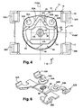
Figure 4 is a top view of the switch shown inFigure 2 ; -
Figure 5 is a view to a larger scale in section on a median longitudinal vertical plane of the switch fromFigure 1 without its actuating plunger; -
Figure 6 is a detail view showing in perspective the metal contact bands of the switch shown inFigure 2 in particular before moulding the insulative casing. - To facilitate an understanding of the following description and to make the claims clear, the terms vertical, horizontal, longitudinal, transversal, etc. are used without limiting the invention and without reference to terrestrial gravity, referring to the system of axes L, V, T shown in the figures.
- In the following description, identical, similar or like components are designated by the same references.
-
Figures 1 to 6 show a double-actionelectrical switch 10 of the invention which is represented here in a nonlimiting manner in the form of a discrete unitary component intended in particular to be soldered and thus fixed to a printed circuit board (PCB) 12 four parts of which are shown in the figures. - The
electrical switch 10 has a generally symmetrical design with respect to the vertical and longitudinal median plane PVML indicated inFigure 4 . - In a general manner known in the art, the
switch 10 essentially consists of a base orcasing 14 of rectangular parallelepiped general shape that is produced by moulding it from an electrically insulative plastic material. - The
casing 14 is notably delimited by its horizontalupper face 16 and by its horizontallower face 18. - In its central part the
casing 14 includes ahousing 20 in theupper face 16 which is open vertically upwards and is delimited by a planehorizontal bottom 22 and by a concave cylindrical verticallateral wall 23. - With the components assembled, the
housing 20 houses theannular return spring 24 and at least part of the triggeringmember 26, while here the actuating member orplunger 28 extends vertically above the plane of theupper face 16. - In the assembled position of the components shown in Figure 10, the switch is covered by a closure and sealing film (not shown) that seals and closes the top of the
housing 20 and to which theplunger 28 is glued. - According to a technique known in the art, the
casing 14 is moulded around cut and bent metal strips, shown inFigure 6 , that constitute the fixed contacts and the associated connecting terminals. - Thus the
switch 10 includes, in the bottom of thehousing 20, first and second fixedperipheral contacts terminal circuit board 12. - Each peripheral fixed
contact vertical wall 23 of thehousing 20 and takes the form of a circular patch which here projects vertically so that its free horizontalupper face bottom 22 of thehousing 20 constitutes. - Similarly, the switch includes a central common fixed
third contact 36 electrically connected to two otherelectrical connecting terminals circuit board 12. - The central fixed
contact 36 is also produced in the form of a circular patch theupper face 40 of which lies in a horizontal plane at a height relative to theplane bottom 22 that is slightly less than that of theupper faces - The shape of the metal strips cut out with the fixed electrical contact patches is shown in detail in
Figure 6 . - In the bottom of the
housing 20 there is astud 42 for locating thereturn spring 24 which projects vertically upward and is in one piece with the moulded insulative plastic material. - As may be seen in
Figure 4 in particular, the verticallateral wall 23 of thehousing 20 includes a first part with a semicircular concave cylindrical profile, at the bottom inFigure 4 , in which thestud 42 is arranged and which is centred on the central vertical axis VA of the switch which corresponds to the vertical actuating axis. - The other part or half of the vertical
lateral axis 23 follows an oblong contour that passes around the first and second fixedperipheral contacts - The
housing 20 receives and locates theannular return spring 24 in an initial high rest position of the triggeringdome 26. - Here the
spring 24 is a member of generally annular shape produced by cutting and bending sheet metal, for example, or by moulding a plastic material, thespring 24 having no electrical conduction function here. - The generally
annular spring 24 includes a rigid first part or section of substantiallysemicircular ring shape 44 which is situated in the lower half ofFigure 4 and the contour and the width of which are complementary to the corresponding part of thevertical wall 23 of thehousing 20 and the locatingstud 42. - As may be seen in
Figure 5 , this rigid first section lies in a plane and theannular spring 24 bears at all times against thebottom 22 via itslower edge 46, which is transversely oriented, and which constitutes a rocking axis of therigid section 44 during elastic deformation of the spring 24 (see below). - The complementary shapes of the
stud 42 and the facing portion of therigid section 44 and of thewall 23 of thehousing 20 locate thespring 24 in thehousing 20 with clearance, notably so that the spring cannot turn in its housing and its movements are limited to the rocking mentioned above during its elastic deformation. - The second part or
section 48 of thespring 24, corresponding to the upper part ofFigure 4 , extending above the median transverse vertical plane PVML, consists essentially of two elasticallydeformable branches tip 52. - As may be seen in
Figure 5 in particular, in the undeformed rest state of thespring 24 thebranches first section 44, vertically downward in the direction of the bottom 22, so as to bear on that bottom 22 and to confer upon the general plane of thefirst section 44 an orientation inclined at an angle alpha relative to the horizontal plane of the bottom 22. - Starting from the high rest position of the
spring 24 shown inFigure 5 , in which the latter spring is not elastically deformed (or only very slightly deformed to take up play), if therigid section 44 is depressed vertically, thebranches upper face 45 of thefirst section 44 lies in a substantially horizontal plane, causing thespring 24 to rock about theedge 46 in the clockwise direction as seen inFigure 5 . - The plane semicircular annular
upper face 45 of thefirst section 44 of thespring 24 constitutes a bearing plane for the lower peripheral annular area of the triggeringmember 26, which here is a circular contour spherical dome the concave side of which faces downward. - The dimensions the
dome 26, and in particular its outside diameter, are such that it is at least partly housed and located in thehousing 20. - The
dome 26, the general design of which is known in the art, notably for producing a tactile effect when it is elastically deformed with a sudden change of state, is electrically conductive, at least on its concave interior and lower face. - The lower peripheral annual area of the
dome 26 that bears on thefirst section 44 of thespring 24 consists here of this peripheral lowercircular edge 54. - As may be seen in
Figure 5 , in the rest position of the switch, i.e. when the user is not exerting any force on theactuating plunger 28, thedome 26 is inclined at the angle alpha, like thespring 24, and the part of itslower edge 54 facing the upper faces 34A and 34B of the two peripheralfixed contacts edge 54 and the peripheralfixed contacts - When, by means of the
plunger 28, the user exerts a force on the convexupper face 27 of thedome 26, in the vertical direction of the arrow F inFigure 5 (this force being substantially centred on the vertical axis VA), given the relative elasticities and stiffnesses of thedome 26 and thespring 24, the first pressure force exerted on thedome 26 causes no elastic deformation of thedome 26 which, bearing on therigid section 44, initially causes elastic deformation of thereturn spring 24. - This deformation of the
spring 24 causes rocking of the triggeringdome 26 leading to bearing engagement and electrical contact of itslower edge 54 with the coplanar upper faces 34A, 34B of the peripheralfixed contacts - The
dome 26 is thus moved from its initial high rest position shown inFigure 5 (toward which it is urged elastically by the spring 24) toward its low final switching position in which its annularperipheral edge 54 bears on the two first peripheral fixedcontacts terminals - At the end of the actuation first phase, the
spring 24 is substantially "flat" and thedome 26 is in a "classic" position in which its lower peripheral annular area bears on a horizontal plane to enable thereafter its "classic" sudden change of state. - Then, on continuing application of a push force of higher value in the direction of the arrow F, the user causes elastic deformation of the
dome 26 and its sudden change of state, as known in the art. At the end of this deformation, the conductive lower face of the central part of thedome 26 comes into electrical contact with theupper face 40 of the central fixedcontact 36. - Apart from the tactile sensation that it gives the user, this deformation then makes the second electrical switchpath between the central fixed
contact 36 and the peripheralfixed contacts terminals - For example, for a
dome 26 with a diameter of 2 mm, the first actuating stroke is equal to approximately 0.1 mm with a force of 1 Newton while the second actuating stroke is equal to approximately 0.2 mm with an actuating force equal to 2.5 Newtons. - The peripheral annular area and/or the lower
free edge 54 of thedome 26, via its conductive lower face, makes directly the electrical contact between the two fixedcontacts 30A. - The invention is not limited to the two embodiments that have just been described.
- For example, the fixed contacts could be part of a rigid or flexible printed circuit board.
- Nor is the invention limited to two fixed peripheral contacts.
- The
annular return spring 24 could be associated with the lower face of a triggeringdome 26. - The design of the invention that has just been described is particularly compact as much in height as laterally, the height being only increased (relative to a standard single-action dome switch) by the thickness or vertical height necessary for the deformation of the return spring.
- The invention is not limited to a switch actuated by a vertical plunger, and may also find applications with lateral actuation with a movement direction-changer along the vertical axis to act at the centre of the
dome 26.
Claims (5)
- Double-action tactile-effect electrical switch (10) including:- an insulative support (14) an upper face of which that lies in a horizontal plane (22) carries at least three fixed electrical contacts including a peripheral first contact (30A), a peripheral second contact (30B), and a central third contact (36);- a triggering member (26), which is elastically deformable from a stable rest state by the action of an actuating member (28) acting in a globally vertical direction (VA), which includes a lower peripheral annular area (54) adapted to come simultaneously into bearing engagement with said two first peripheral contacts (30A, 30B) to make a first switchpath, and a domed upper central section on which the actuating member (28) acts, which member is deformable in order to make an electrical connection between on the one hand said two fixed first contacts (30A, 30B) and on the other hand said central third electrical contact (36), to make a second switchpath consecutively to the making the first switchpath;wherein in its stable rest state, the triggering member (26) can occupy:- an initial high rest position toward which it is urged elastically and in which said annular area (54) does not bear on the two peripheral fixed first contacts (30A, 30B); and- a final low switching position toward which it is moved by the actuating member, against said return spring force, and in which said annular area (54) of the triggering member (26) bears directly or indirectly on the two first peripheral fixed contacts (30A, 30B)wherein the switch (10) includes a spring return member (24) that is disposed vertically between the support (14) and the triggering member (26) and which is compressible globally vertically to enable the triggering member (26) to move from its initial high position to its final low position,
characterized in that, in said initial high position of the triggering member (26), the lower peripheral edge (54) that delimits said annular area lies in a plane that forms an acute angle (alpha) with said horizontal plane, and, in said low final position, said lower peripheral edge (54) lies in a plane parallel to said horizontal plane and bears on the two first peripheral fixed contacts (30A, 30B). - Switch according to Claim 1, characterized in that said spring return member (24) is a ring that includes a rigid bearing section (44) on which a section of said lower peripheral edge (54) bears and an elastically deformable section (48), this ring being elastically deformable between a stable rest state in which said rigid section (44) lies in a plane that forms an acute angle (alpha) with said horizontal plane and an elastically compressed final state in which said rigid section (44) extends horizontally and bears on said horizontal upper face (22).
- Switch according to Claim 2, characterized in that the elastically deformable section (48) of the return ring includes two elastically deformable branches (50A, 50B) which join at a point that bears on said horizontal upper face (22) situated between said two first peripheral fixed contacts (30A, 30B).
- Switch according to Claim 1 , characterized in that the triggering member is a spherical dome (26).
- Switch according to Claim 1, characterized in that it includes a contact support (14) for contacts (30A, 30B, 36) that delimits a housing (20) the bottom (22) of which is delimited by said horizontal upper surface.
Applications Claiming Priority (1)
| Application Number | Priority Date | Filing Date | Title |
|---|---|---|---|
| FR1051554A FR2957187B1 (en) | 2010-03-04 | 2010-03-04 | DOUBLE-ACTING TOUCH-EFFECT ELECTRIC SWITCH |
Publications (2)
| Publication Number | Publication Date |
|---|---|
| EP2363872A1 EP2363872A1 (en) | 2011-09-07 |
| EP2363872B1 true EP2363872B1 (en) | 2012-09-19 |
Family
ID=42690963
Family Applications (1)
| Application Number | Title | Priority Date | Filing Date |
|---|---|---|---|
| EP11156439A Active EP2363872B1 (en) | 2010-03-04 | 2011-03-01 | Electrical switch with a dual action tactile effect |
Country Status (4)
| Country | Link |
|---|---|
| US (1) | US8546708B2 (en) |
| EP (1) | EP2363872B1 (en) |
| CN (1) | CN102194593B (en) |
| FR (1) | FR2957187B1 (en) |
Families Citing this family (6)
| Publication number | Priority date | Publication date | Assignee | Title |
|---|---|---|---|---|
| CN102017725A (en) * | 2008-04-28 | 2011-04-13 | 诺基亚公司 | Method and apparatus for providing power saving using superframes |
| USD809467S1 (en) | 2015-03-23 | 2018-02-06 | Citizen Electronics Co., Ltd. | Switch |
| FR3045927B1 (en) * | 2015-12-22 | 2018-01-05 | C&K Components S.A.S. | "ELECTRICAL SWITCH WITH TOUCH-EFFECTIVE TOUCH RATE" |
| CN105489405A (en) * | 2016-01-08 | 2016-04-13 | 谭境华 | A multi-speed speed control switch |
| CN110911200A (en) * | 2019-12-25 | 2020-03-24 | 新考思莫施电子(上海)有限公司 | A new push button switch structure |
| US11487422B2 (en) * | 2020-11-03 | 2022-11-01 | Trent Zimmer | Force sensing dome switch |
Family Cites Families (14)
| Publication number | Priority date | Publication date | Assignee | Title |
|---|---|---|---|---|
| JPS5168726A (en) * | 1974-12-12 | 1976-06-14 | Hosiden Electronics Co | |
| JPS5524351A (en) * | 1978-08-09 | 1980-02-21 | Alps Electric Co Ltd | Pushhbutton switch |
| US4385218A (en) * | 1981-04-21 | 1983-05-24 | Matsushita Electric Industrial Co., Ltd. | Electric switch |
| US4359614A (en) | 1981-09-24 | 1982-11-16 | Illinois Tool Works Inc. | Miniature two-level pushbutton switch |
| US4659881A (en) | 1986-01-27 | 1987-04-21 | Eastman Kodak Company | Multidome multistage switch assembly |
| US5564560A (en) | 1995-06-07 | 1996-10-15 | Garmin Corporation | Dual function button |
| US5898147A (en) | 1997-10-29 | 1999-04-27 | C & K Components, Inc. | Dual tact switch assembly |
| FR2796754B1 (en) | 1999-07-19 | 2002-04-12 | Cit Alcatel | DOUBLE PRESSURE SWITCH |
| JP4069555B2 (en) * | 1999-10-06 | 2008-04-02 | 松下電器産業株式会社 | Push switch |
| JP4075608B2 (en) * | 2002-03-13 | 2008-04-16 | 松下電器産業株式会社 | Push-on switch |
| JP4088577B2 (en) * | 2003-10-16 | 2008-05-21 | ホシデン株式会社 | Movable contact for push-on switch and push-on switch |
| CN2916887Y (en) * | 2006-07-11 | 2007-06-27 | 富士康(昆山)电脑接插件有限公司 | power switch button |
| US7902474B2 (en) * | 2008-05-01 | 2011-03-08 | Apple Inc. | Button assembly with inverted dome switch |
| JP5083057B2 (en) * | 2008-06-13 | 2012-11-28 | パナソニック株式会社 | Push switch |
-
2010
- 2010-03-04 FR FR1051554A patent/FR2957187B1/en not_active Expired - Fee Related
-
2011
- 2011-03-01 EP EP11156439A patent/EP2363872B1/en active Active
- 2011-03-04 US US13/040,581 patent/US8546708B2/en active Active
- 2011-03-04 CN CN201110052000.2A patent/CN102194593B/en active Active
Also Published As
| Publication number | Publication date |
|---|---|
| US8546708B2 (en) | 2013-10-01 |
| EP2363872A1 (en) | 2011-09-07 |
| CN102194593A (en) | 2011-09-21 |
| US20110214969A1 (en) | 2011-09-08 |
| CN102194593B (en) | 2015-05-20 |
| FR2957187B1 (en) | 2012-10-26 |
| FR2957187A1 (en) | 2011-09-09 |
Similar Documents
| Publication | Publication Date | Title |
|---|---|---|
| US20110303520A1 (en) | Double action electrical switch with a tactile effect | |
| US6794589B2 (en) | Multiple electrical switch arrangement | |
| US7964815B2 (en) | Push-button switch | |
| US8546708B2 (en) | Electrical switch with a tactile effect and a dual action | |
| US7368672B2 (en) | Push-on switch | |
| JP3165574U (en) | Metal dome switch for keypad | |
| US6621017B2 (en) | Push-button switch and multiple switch using the same | |
| JP2011100549A (en) | Push switch | |
| US8188388B2 (en) | Operation key structure | |
| JP5284883B2 (en) | Push-button switch | |
| JP5428752B2 (en) | Press switch | |
| JP2005019112A (en) | Push-button switch | |
| JP2000076959A (en) | Push-button operation switch with two-stage operation function with click feeling | |
| US20110083950A1 (en) | Multi-directional tact switch | |
| JP4148714B2 (en) | Push button switch | |
| JP2008181897A (en) | Push-button switch | |
| JP4332543B2 (en) | Side push type push switch | |
| US20040238341A1 (en) | Tact switch | |
| US20010052452A1 (en) | Low-profile flip-over contact piece for tactile switch | |
| JPH0338740Y2 (en) | ||
| JP2002313189A (en) | Multi directional switch | |
| JP2641779B2 (en) | Push button switch | |
| KR20060045687A (en) | Pushbutton switch | |
| JP2002190237A (en) | Multi-directional switch | |
| JP2007200737A (en) | Push-button switch |
Legal Events
| Date | Code | Title | Description |
|---|---|---|---|
| PUAI | Public reference made under article 153(3) epc to a published international application that has entered the european phase |
Free format text: ORIGINAL CODE: 0009012 |
|
| AK | Designated contracting states |
Kind code of ref document: A1 Designated state(s): AL AT BE BG CH CY CZ DE DK EE ES FI FR GB GR HR HU IE IS IT LI LT LU LV MC MK MT NL NO PL PT RO RS SE SI SK SM TR |
|
| AX | Request for extension of the european patent |
Extension state: BA ME |
|
| RAP1 | Party data changed (applicant data changed or rights of an application transferred) |
Owner name: COACTIVE TECHNOLOGIES, LLC |
|
| 17P | Request for examination filed |
Effective date: 20120126 |
|
| GRAP | Despatch of communication of intention to grant a patent |
Free format text: ORIGINAL CODE: EPIDOSNIGR1 |
|
| RIC1 | Information provided on ipc code assigned before grant |
Ipc: H01H 13/48 20060101ALI20120403BHEP Ipc: H01H 1/64 20060101AFI20120403BHEP |
|
| GRAS | Grant fee paid |
Free format text: ORIGINAL CODE: EPIDOSNIGR3 |
|
| GRAA | (expected) grant |
Free format text: ORIGINAL CODE: 0009210 |
|
| AK | Designated contracting states |
Kind code of ref document: B1 Designated state(s): AL AT BE BG CH CY CZ DE DK EE ES FI FR GB GR HR HU IE IS IT LI LT LU LV MC MK MT NL NO PL PT RO RS SE SI SK SM TR |
|
| REG | Reference to a national code |
Ref country code: GB Ref legal event code: FG4D |
|
| REG | Reference to a national code |
Ref country code: CH Ref legal event code: EP |
|
| REG | Reference to a national code |
Ref country code: IE Ref legal event code: FG4D |
|
| REG | Reference to a national code |
Ref country code: AT Ref legal event code: REF Ref document number: 576372 Country of ref document: AT Kind code of ref document: T Effective date: 20121015 |
|
| REG | Reference to a national code |
Ref country code: DE Ref legal event code: R096 Ref document number: 602011000228 Country of ref document: DE Effective date: 20121115 |
|
| RAP2 | Party data changed (patent owner data changed or rights of a patent transferred) |
Owner name: COACTIVE TECHNOLOGIES, LLC |
|
| PG25 | Lapsed in a contracting state [announced via postgrant information from national office to epo] |
Ref country code: NO Free format text: LAPSE BECAUSE OF FAILURE TO SUBMIT A TRANSLATION OF THE DESCRIPTION OR TO PAY THE FEE WITHIN THE PRESCRIBED TIME-LIMIT Effective date: 20121219 Ref country code: HR Free format text: LAPSE BECAUSE OF FAILURE TO SUBMIT A TRANSLATION OF THE DESCRIPTION OR TO PAY THE FEE WITHIN THE PRESCRIBED TIME-LIMIT Effective date: 20120919 Ref country code: LT Free format text: LAPSE BECAUSE OF FAILURE TO SUBMIT A TRANSLATION OF THE DESCRIPTION OR TO PAY THE FEE WITHIN THE PRESCRIBED TIME-LIMIT Effective date: 20120919 Ref country code: FI Free format text: LAPSE BECAUSE OF FAILURE TO SUBMIT A TRANSLATION OF THE DESCRIPTION OR TO PAY THE FEE WITHIN THE PRESCRIBED TIME-LIMIT Effective date: 20120919 |
|
| REG | Reference to a national code |
Ref country code: NL Ref legal event code: VDEP Effective date: 20120919 |
|
| REG | Reference to a national code |
Ref country code: AT Ref legal event code: MK05 Ref document number: 576372 Country of ref document: AT Kind code of ref document: T Effective date: 20120919 |
|
| REG | Reference to a national code |
Ref country code: LT Ref legal event code: MG4D Effective date: 20120919 |
|
| PG25 | Lapsed in a contracting state [announced via postgrant information from national office to epo] |
Ref country code: SE Free format text: LAPSE BECAUSE OF FAILURE TO SUBMIT A TRANSLATION OF THE DESCRIPTION OR TO PAY THE FEE WITHIN THE PRESCRIBED TIME-LIMIT Effective date: 20120919 Ref country code: LV Free format text: LAPSE BECAUSE OF FAILURE TO SUBMIT A TRANSLATION OF THE DESCRIPTION OR TO PAY THE FEE WITHIN THE PRESCRIBED TIME-LIMIT Effective date: 20120919 Ref country code: SI Free format text: LAPSE BECAUSE OF FAILURE TO SUBMIT A TRANSLATION OF THE DESCRIPTION OR TO PAY THE FEE WITHIN THE PRESCRIBED TIME-LIMIT Effective date: 20120919 Ref country code: GR Free format text: LAPSE BECAUSE OF FAILURE TO SUBMIT A TRANSLATION OF THE DESCRIPTION OR TO PAY THE FEE WITHIN THE PRESCRIBED TIME-LIMIT Effective date: 20121220 |
|
| PG25 | Lapsed in a contracting state [announced via postgrant information from national office to epo] |
Ref country code: RO Free format text: LAPSE BECAUSE OF FAILURE TO SUBMIT A TRANSLATION OF THE DESCRIPTION OR TO PAY THE FEE WITHIN THE PRESCRIBED TIME-LIMIT Effective date: 20120919 Ref country code: NL Free format text: LAPSE BECAUSE OF FAILURE TO SUBMIT A TRANSLATION OF THE DESCRIPTION OR TO PAY THE FEE WITHIN THE PRESCRIBED TIME-LIMIT Effective date: 20120919 Ref country code: IS Free format text: LAPSE BECAUSE OF FAILURE TO SUBMIT A TRANSLATION OF THE DESCRIPTION OR TO PAY THE FEE WITHIN THE PRESCRIBED TIME-LIMIT Effective date: 20130119 Ref country code: CZ Free format text: LAPSE BECAUSE OF FAILURE TO SUBMIT A TRANSLATION OF THE DESCRIPTION OR TO PAY THE FEE WITHIN THE PRESCRIBED TIME-LIMIT Effective date: 20120919 Ref country code: BE Free format text: LAPSE BECAUSE OF FAILURE TO SUBMIT A TRANSLATION OF THE DESCRIPTION OR TO PAY THE FEE WITHIN THE PRESCRIBED TIME-LIMIT Effective date: 20120919 Ref country code: EE Free format text: LAPSE BECAUSE OF FAILURE TO SUBMIT A TRANSLATION OF THE DESCRIPTION OR TO PAY THE FEE WITHIN THE PRESCRIBED TIME-LIMIT Effective date: 20120919 |
|
| PG25 | Lapsed in a contracting state [announced via postgrant information from national office to epo] |
Ref country code: SK Free format text: LAPSE BECAUSE OF FAILURE TO SUBMIT A TRANSLATION OF THE DESCRIPTION OR TO PAY THE FEE WITHIN THE PRESCRIBED TIME-LIMIT Effective date: 20120919 Ref country code: PT Free format text: LAPSE BECAUSE OF FAILURE TO SUBMIT A TRANSLATION OF THE DESCRIPTION OR TO PAY THE FEE WITHIN THE PRESCRIBED TIME-LIMIT Effective date: 20130121 Ref country code: PL Free format text: LAPSE BECAUSE OF FAILURE TO SUBMIT A TRANSLATION OF THE DESCRIPTION OR TO PAY THE FEE WITHIN THE PRESCRIBED TIME-LIMIT Effective date: 20120919 |
|
| PG25 | Lapsed in a contracting state [announced via postgrant information from national office to epo] |
Ref country code: AT Free format text: LAPSE BECAUSE OF FAILURE TO SUBMIT A TRANSLATION OF THE DESCRIPTION OR TO PAY THE FEE WITHIN THE PRESCRIBED TIME-LIMIT Effective date: 20120919 |
|
| PLBE | No opposition filed within time limit |
Free format text: ORIGINAL CODE: 0009261 |
|
| STAA | Information on the status of an ep patent application or granted ep patent |
Free format text: STATUS: NO OPPOSITION FILED WITHIN TIME LIMIT |
|
| PG25 | Lapsed in a contracting state [announced via postgrant information from national office to epo] |
Ref country code: RS Free format text: LAPSE BECAUSE OF FAILURE TO SUBMIT A TRANSLATION OF THE DESCRIPTION OR TO PAY THE FEE WITHIN THE PRESCRIBED TIME-LIMIT Effective date: 20120919 Ref country code: BG Free format text: LAPSE BECAUSE OF FAILURE TO SUBMIT A TRANSLATION OF THE DESCRIPTION OR TO PAY THE FEE WITHIN THE PRESCRIBED TIME-LIMIT Effective date: 20121219 Ref country code: DK Free format text: LAPSE BECAUSE OF FAILURE TO SUBMIT A TRANSLATION OF THE DESCRIPTION OR TO PAY THE FEE WITHIN THE PRESCRIBED TIME-LIMIT Effective date: 20120919 |
|
| 26N | No opposition filed |
Effective date: 20130620 |
|
| PG25 | Lapsed in a contracting state [announced via postgrant information from national office to epo] |
Ref country code: IT Free format text: LAPSE BECAUSE OF FAILURE TO SUBMIT A TRANSLATION OF THE DESCRIPTION OR TO PAY THE FEE WITHIN THE PRESCRIBED TIME-LIMIT Effective date: 20120919 |
|
| REG | Reference to a national code |
Ref country code: DE Ref legal event code: R097 Ref document number: 602011000228 Country of ref document: DE Effective date: 20130620 |
|
| PG25 | Lapsed in a contracting state [announced via postgrant information from national office to epo] |
Ref country code: ES Free format text: LAPSE BECAUSE OF FAILURE TO SUBMIT A TRANSLATION OF THE DESCRIPTION OR TO PAY THE FEE WITHIN THE PRESCRIBED TIME-LIMIT Effective date: 20121230 Ref country code: MC Free format text: LAPSE BECAUSE OF NON-PAYMENT OF DUE FEES Effective date: 20130331 |
|
| PG25 | Lapsed in a contracting state [announced via postgrant information from national office to epo] |
Ref country code: CY Free format text: LAPSE BECAUSE OF FAILURE TO SUBMIT A TRANSLATION OF THE DESCRIPTION OR TO PAY THE FEE WITHIN THE PRESCRIBED TIME-LIMIT Effective date: 20120919 |
|
| REG | Reference to a national code |
Ref country code: IE Ref legal event code: MM4A |
|
| PG25 | Lapsed in a contracting state [announced via postgrant information from national office to epo] |
Ref country code: AL Free format text: LAPSE BECAUSE OF FAILURE TO SUBMIT A TRANSLATION OF THE DESCRIPTION OR TO PAY THE FEE WITHIN THE PRESCRIBED TIME-LIMIT Effective date: 20120919 Ref country code: IE Free format text: LAPSE BECAUSE OF NON-PAYMENT OF DUE FEES Effective date: 20130301 |
|
| PG25 | Lapsed in a contracting state [announced via postgrant information from national office to epo] |
Ref country code: MT Free format text: LAPSE BECAUSE OF FAILURE TO SUBMIT A TRANSLATION OF THE DESCRIPTION OR TO PAY THE FEE WITHIN THE PRESCRIBED TIME-LIMIT Effective date: 20120919 |
|
| REG | Reference to a national code |
Ref country code: CH Ref legal event code: PL |
|
| PG25 | Lapsed in a contracting state [announced via postgrant information from national office to epo] |
Ref country code: CH Free format text: LAPSE BECAUSE OF NON-PAYMENT OF DUE FEES Effective date: 20140331 Ref country code: LI Free format text: LAPSE BECAUSE OF NON-PAYMENT OF DUE FEES Effective date: 20140331 |
|
| REG | Reference to a national code |
Ref country code: FR Ref legal event code: PLFP Year of fee payment: 5 |
|
| PG25 | Lapsed in a contracting state [announced via postgrant information from national office to epo] |
Ref country code: SM Free format text: LAPSE BECAUSE OF FAILURE TO SUBMIT A TRANSLATION OF THE DESCRIPTION OR TO PAY THE FEE WITHIN THE PRESCRIBED TIME-LIMIT Effective date: 20120919 |
|
| PG25 | Lapsed in a contracting state [announced via postgrant information from national office to epo] |
Ref country code: TR Free format text: LAPSE BECAUSE OF FAILURE TO SUBMIT A TRANSLATION OF THE DESCRIPTION OR TO PAY THE FEE WITHIN THE PRESCRIBED TIME-LIMIT Effective date: 20120919 |
|
| PG25 | Lapsed in a contracting state [announced via postgrant information from national office to epo] |
Ref country code: HU Free format text: LAPSE BECAUSE OF FAILURE TO SUBMIT A TRANSLATION OF THE DESCRIPTION OR TO PAY THE FEE WITHIN THE PRESCRIBED TIME-LIMIT; INVALID AB INITIO Effective date: 20110301 Ref country code: LU Free format text: LAPSE BECAUSE OF NON-PAYMENT OF DUE FEES Effective date: 20130301 Ref country code: MK Free format text: LAPSE BECAUSE OF FAILURE TO SUBMIT A TRANSLATION OF THE DESCRIPTION OR TO PAY THE FEE WITHIN THE PRESCRIBED TIME-LIMIT Effective date: 20120919 |
|
| GBPC | Gb: european patent ceased through non-payment of renewal fee |
Effective date: 20150301 |
|
| PG25 | Lapsed in a contracting state [announced via postgrant information from national office to epo] |
Ref country code: GB Free format text: LAPSE BECAUSE OF NON-PAYMENT OF DUE FEES Effective date: 20150301 |
|
| REG | Reference to a national code |
Ref country code: FR Ref legal event code: PLFP Year of fee payment: 6 |
|
| REG | Reference to a national code |
Ref country code: FR Ref legal event code: PLFP Year of fee payment: 7 |
|
| REG | Reference to a national code |
Ref country code: FR Ref legal event code: PLFP Year of fee payment: 8 |
|
| P01 | Opt-out of the competence of the unified patent court (upc) registered |
Effective date: 20230607 |
|
| PGFP | Annual fee paid to national office [announced via postgrant information from national office to epo] |
Ref country code: DE Payment date: 20241231 Year of fee payment: 15 |
|
| PGFP | Annual fee paid to national office [announced via postgrant information from national office to epo] |
Ref country code: FR Payment date: 20251231 Year of fee payment: 16 |