EP2363753A1 - Developer cartridge for image-forming device - Google Patents
Developer cartridge for image-forming device Download PDFInfo
- Publication number
- EP2363753A1 EP2363753A1 EP11000815A EP11000815A EP2363753A1 EP 2363753 A1 EP2363753 A1 EP 2363753A1 EP 11000815 A EP11000815 A EP 11000815A EP 11000815 A EP11000815 A EP 11000815A EP 2363753 A1 EP2363753 A1 EP 2363753A1
- Authority
- EP
- European Patent Office
- Prior art keywords
- developer
- toner
- agitator
- shaft
- accommodating chamber
- Prior art date
- Legal status (The legal status is an assumption and is not a legal conclusion. Google has not performed a legal analysis and makes no representation as to the accuracy of the status listed.)
- Granted
Links
Images








Classifications
-
- G—PHYSICS
- G03—PHOTOGRAPHY; CINEMATOGRAPHY; ANALOGOUS TECHNIQUES USING WAVES OTHER THAN OPTICAL WAVES; ELECTROGRAPHY; HOLOGRAPHY
- G03G—ELECTROGRAPHY; ELECTROPHOTOGRAPHY; MAGNETOGRAPHY
- G03G15/00—Apparatus for electrographic processes using a charge pattern
- G03G15/06—Apparatus for electrographic processes using a charge pattern for developing
- G03G15/08—Apparatus for electrographic processes using a charge pattern for developing using a solid developer, e.g. powder developer
- G03G15/0822—Arrangements for preparing, mixing, supplying or dispensing developer
- G03G15/0865—Arrangements for supplying new developer
- G03G15/0875—Arrangements for supplying new developer cartridges having a box like shape
-
- G—PHYSICS
- G03—PHOTOGRAPHY; CINEMATOGRAPHY; ANALOGOUS TECHNIQUES USING WAVES OTHER THAN OPTICAL WAVES; ELECTROGRAPHY; HOLOGRAPHY
- G03G—ELECTROGRAPHY; ELECTROPHOTOGRAPHY; MAGNETOGRAPHY
- G03G15/00—Apparatus for electrographic processes using a charge pattern
- G03G15/06—Apparatus for electrographic processes using a charge pattern for developing
- G03G15/08—Apparatus for electrographic processes using a charge pattern for developing using a solid developer, e.g. powder developer
- G03G15/0822—Arrangements for preparing, mixing, supplying or dispensing developer
- G03G15/0848—Arrangements for testing or measuring developer properties or quality, e.g. charge, size, flowability
- G03G15/0856—Detection or control means for the developer level
- G03G15/0862—Detection or control means for the developer level the level being measured by optical means
-
- G—PHYSICS
- G03—PHOTOGRAPHY; CINEMATOGRAPHY; ANALOGOUS TECHNIQUES USING WAVES OTHER THAN OPTICAL WAVES; ELECTROGRAPHY; HOLOGRAPHY
- G03G—ELECTROGRAPHY; ELECTROPHOTOGRAPHY; MAGNETOGRAPHY
- G03G15/00—Apparatus for electrographic processes using a charge pattern
- G03G15/06—Apparatus for electrographic processes using a charge pattern for developing
- G03G15/08—Apparatus for electrographic processes using a charge pattern for developing using a solid developer, e.g. powder developer
- G03G15/0822—Arrangements for preparing, mixing, supplying or dispensing developer
- G03G15/0877—Arrangements for metering and dispensing developer from a developer cartridge into the development unit
-
- G—PHYSICS
- G03—PHOTOGRAPHY; CINEMATOGRAPHY; ANALOGOUS TECHNIQUES USING WAVES OTHER THAN OPTICAL WAVES; ELECTROGRAPHY; HOLOGRAPHY
- G03G—ELECTROGRAPHY; ELECTROPHOTOGRAPHY; MAGNETOGRAPHY
- G03G2215/00—Apparatus for electrophotographic processes
- G03G2215/08—Details of powder developing device not concerning the development directly
- G03G2215/0802—Arrangements for agitating or circulating developer material
-
- G—PHYSICS
- G03—PHOTOGRAPHY; CINEMATOGRAPHY; ANALOGOUS TECHNIQUES USING WAVES OTHER THAN OPTICAL WAVES; ELECTROGRAPHY; HOLOGRAPHY
- G03G—ELECTROGRAPHY; ELECTROPHOTOGRAPHY; MAGNETOGRAPHY
- G03G2215/00—Apparatus for electrophotographic processes
- G03G2215/08—Details of powder developing device not concerning the development directly
- G03G2215/0888—Arrangements for detecting toner level or concentration in the developing device
- G03G2215/0891—Optical detection
- G03G2215/0894—Optical detection through a light transmissive window in the developer container wall
- G03G2215/0897—Cleaning of the light transmissive window
-
- G—PHYSICS
- G03—PHOTOGRAPHY; CINEMATOGRAPHY; ANALOGOUS TECHNIQUES USING WAVES OTHER THAN OPTICAL WAVES; ELECTROGRAPHY; HOLOGRAPHY
- G03G—ELECTROGRAPHY; ELECTROPHOTOGRAPHY; MAGNETOGRAPHY
- G03G2221/00—Processes not provided for by group G03G2215/00, e.g. cleaning or residual charge elimination
- G03G2221/16—Mechanical means for facilitating the maintenance of the apparatus, e.g. modular arrangements and complete machine concepts
- G03G2221/163—Mechanical means for facilitating the maintenance of the apparatus, e.g. modular arrangements and complete machine concepts for the developer unit
Definitions
- the invention relates generally to an image-forming device, such as a laser printer, and more particularly, to a developer cartridge and process cartridge mounted in the image-forming device.
- the above-described conventional developer cartridges have various disadvantages.
- One disadvantage is that the charged excess toner that the thickness-regulating blade scrapes off the surface of the developing roller accumulates in the developing chamber and sometimes returns to the toner-accommodating chamber.
- charge control becomes difficult when tribocharging the toner between the supply roller and the developing roller, leading to a decline in image quality. Therefore, it is desirable to supply as much of the toner that has been previously charged for development as quickly as possible.
- This construction provides the casing with the box-shaped reinforcing part along the edges of the opening in which the developer-carrying member is exposed, thereby effectively reinforcing the edge of the opening, which portion of the casing has less strength. Further, since the reinforcing part is formed in a box shape, the thickness of the casing provided with the reinforcing part can be equivalent to the thickness of the casing in regions other than the reinforcing part, reducing the likelihood of sinks forming during the molding process in the surface opposing the developer-carrying member. Therefore, the opening of the casing can be reliably reinforced while maintaining a precise gap between the developer-carrying member and the edge of the opening.
- the laser printer 1 serving as the image-forming device of the invention includes a main casing 2 and, within the main casing 2, a feeding unit 4 for supplying sheets of a paper 3, an image-forming unit 5 for forming images on the paper 3 supplied by the feeding unit 4.
- the laser printer 1 also includes an access opening 6 formed in one side wall of the main casing 2 for inserting and removing a process cartridge 20 described later, and a front cover 7 capable of opening and closing over the access opening 6.
- the front cover 7 is rotatably supported by a cover shaft 8 inserted through a bottom edge of the front cover 7. Accordingly, when the front cover 7 is rotated closed about the cover shaft 8, the front cover 7 covers the access opening 6, as shown in Fig. 1 . When the front cover 7 is rotated open about the cover shaft 8, the access opening 6 is exposed, enabling the process cartridge 20 to be mounted into or removed from the main casing 2 via the access opening 6.
- the side of the laser printer 1 on which the front cover 7 is mounted and the corresponding side of the process cartridge 20 when the process cartridge 20 is mounted in the main casing 2 will be referred to as the "front side,” while the opposite side will be referred to as the "rear side.”
- the feeding unit 4 includes a paper tray 9 that can be inserted into or removed from a lower section of the main casing 2 in the front-to-rear direction, a separating roller 10 and a separating pad 11 disposed above a front end of the paper tray 9, and a feeding roller 12 disposed on the rear side of the separating roller 10 upstream of the separating pad 11 with respect to the conveying direction of the paper 3 (hereinafter referred to as the "paper-conveying direction").
- the feeding unit 4 also includes a paper dust roller 13 disposed above and forward of the separating roller 10 and downstream of the separating roller 10 in the paper-conveying direction, and a pinch roller 14 disposed in opposition to the paper dust roller 13.
- a paper-conveying path for the paper 3 on the feeding end reverses directions toward the rear side of the laser printer 1, forming a substantial U-shape near the paper dust roller 13.
- the feeding unit 4 also includes a pair of registration rollers 15 disposed below the process cartridge 20 farther downstream of the U-shaped portion of the paper-conveying path with respect to the paper-conveying direction.
- a paper-pressing plate 16 is provided inside the paper tray 9 for supporting the paper 3 in a stacked state.
- the paper-pressing plate 16 is pivotably supported on the rear end thereof, so that the front end can pivot downward to a resting position in which the paper-pressing plate 16 rests on a bottom plate of the paper tray 9 and can pivot upward to a feeding position in which the paper-pressing plate 16 slopes upward from the rear end to the front end.
- a lever 17 is provided in the front section of the paper tray 9 for lifting the front end of the paper-pressing plate 16 upward.
- the rear end of the lever 17 is pivotably supported on a lever shaft 18 at a position below the front end of the paper-pressing plate 16 so that the front end of the lever 17 can pivot between a level position in which the lever 17 lies along the bottom plate of the paper tray 9 and a sloped position in which the front end of the lever 17 lifts the paper-pressing plate 16 upward.
- the topmost sheet of paper 3 stacked on the paper-pressing plate 16 is pressed against the feeding roller 12.
- the rotating feeding roller 12 begins feeding the sheets of paper 3 toward a separating position between the separating roller 10 and separating pad 11.
- the paper-pressing plate 16 When the paper tray 9 is removed from the main casing 2, the paper-pressing plate 16 settles into the resting position. While the paper-pressing plate 16 is in the resting position, the paper 3 can be stacked on the paper-pressing plate 16.
- the rotating separating roller 10 separates and feeds the paper 3 one sheet at a time.
- Each sheet of paper 3 fed by the separating roller 10 passes between the paper dust roller 13 and pinch roller 14.
- the paper dust roller 13 removes paper dust from the sheet of paper 3
- the sheet is conveyed along the U-shaped paper-conveying path on the feeding end, thereby reversing directions in the main casing 2, and is conveyed toward the registration rollers 15.
- the registration rollers 15 convey the paper 3 to a transfer position between a photosensitive drum 28 and a transfer roller 31 described later, at which position a toner image formed on the photosensitive drum 28 is transferred onto the paper 3.
- the scanning unit 19 is disposed in a top section of the main casing 2 and includes a laser light source (not shown), a polygon mirror 22 that can be driven to rotate, an f ⁇ lens 23, a reflecting mirror 24, a lens 25, and a reflecting mirror 26.
- the laser light source emits a laser beam based on image data. As illustrated by a dotted line in Fig. 1 , the laser beam is deflected by the polygon mirror 22, passes through the f ⁇ lens 23, is reflected by the reflecting mirror 24, passes through the lens 25, and is reflected downward by the reflecting mirror 26 to be irradiated on the surface of the photosensitive drum 28 in the process cartridge 20.
- the drum cartridge 27 includes a drum side casing 76 and, within the drum side casing 76, the photosensitive drum 28, a Scorotron charger 29, the transfer roller 31, and a cleaning member 32.
- the photosensitive drum 28 includes a main drum body 33 that is cylindrical in shape and has a positive charging photosensitive layer formed of polycarbonate or the like on its outer surface, and a metal drum shaft 34 extending through the center of the main drum body 33 along the axial direction thereof.
- the metal drum shaft 34 is supported in the drum cartridge 27, and the main drum body 33 is rotatably supported relative to the metal drum shaft 34.
- the photosensitive drum 28 is disposed in the drum cartridge 27 and is capable of rotating about the metal drum shaft 34. Further, the photosensitive drum 28 is driven to rotate by a driving force inputted from a motor (not shown).
- the developer cartridge 30 includes a casing 36 and, within the casing 36, a supply roller 37, a developing roller 38, and a thickness-regulating blade 39.
- the developer cartridge 30 is detachably mounted on the drum cartridge 27. Accordingly, when the process cartridge 20 is mounted in the main casing 2, the developer cartridge 30 can be mounted in the main casing 2 by first opening the front cover 7 and subsequently inserting the developer cartridge 30 through the access opening 6 and mounting the developer cartridge 30 on the process cartridge 20.
- Toner discharged through the opening 43 is supplied onto the developing roller 38 by the rotating supply roller 37. At this time, the toner is positively tribocharged between the supply roller 37 and the developing roller 38. As the developing roller 38 rotates, the toner supplied to the surface of the developing roller 38 passes between the rubber roller 53 of the developing roller 38 and the pressing part 55 of the thickness-regulating blade 39, thereby maintaining a uniform thickness of toner on the surface of the developing roller 38.
- the registration rollers 15 convey a sheet of the paper 3 into the drum cartridge 27 via the pre-drum opening 113 and through the transfer position between the photosensitive drum 28 and transfer roller 31, the toner image carried on the surface of the surface of the photosensitive drum 28 is transferred onto the paper 3 by the transfer bias applied to the transfer roller 31.
- the paper 3 is conveyed out of the drum cartridge 27 via the post-drum opening 114 and is conveyed to the fixing unit 21.
- the fixing unit 21 is disposed on the rear side of the process cartridge 20 and includes a fixed frame 59; and a heating roller 60 and a pressure roller 61 provided within the fixed frame 59.
- a toner image transferred onto the paper 3 at the transfer position is fixed to the paper 3 by heat as the paper 3 passes between the heating roller 60 and pressure roller 61. After the toner image is fixed to the paper 3, the heating roller 60 and pressure roller 61 continue to convey the paper 3 along a discharge end paper-conveying path toward a discharge tray 62 formed on the top surface of the main casing 2.
- the paper-conveying path on the discharge end leads from the fixing unit 21 to the discharge tray 62 and is substantially U-shaped for reversing the conveying direction of the paper 3 to a direction toward the front of the laser printer 1.
- a pair of conveying rollers 63 is disposed at a midpoint along the discharge end paper-conveying path, and a pair of discharge rollers 64 is disposed at a downstream end of the same path.
- the top wall 70 is plate-shaped in a plan view and functions to close off the top of the toner-accommodating chamber 41 and developing chamber 42.
- the side walls 69 are plate-shaped and function to close off the sides of the toner-accommodating chamber 41 and developing chamber 42.
- the side walls 69 also rotatably support the rotational shaft 46, roller shaft 50, and roller shaft 52.
- a handle 77 is provided on the front side of the casing 36 for the user to grip when mounting or removing the developer cartridge 30 and process cartridge 20.
- the handle 77 protrudes forward from the top of the front wall 72 constituting the casing 36.
- a gear mechanism (not shown) for driving the rotational shaft 46, roller shaft 50, and roller shaft 52 to rotate, and a gear cover 79 for covering the gear mechanism are provided on one of the side walls 69 constituting the casing 36.
- Two partial rear walls 73 are provided on the lower edge 68 in the opening 94 of the casing 36.
- a reinforcing part 80 is provided on the lower edge 68 of the opening 94.
- the lower edge 68 has a stepped cross-sectional shape configured of the rear step part 97 and front step part 98.
- the lower film 87 is fixed to the lower edge 68 by aligning the rear edge of the lower film 87 with the rear edge of the front step part 98 provided farther forward of the rear step part 97, that is, on the upstream side in the direction that toner leaks through the opening 94. Therefore, if the rear step part 97 contacts another component, the lower film 87 is less likely to peel of the top surface 102 since the lower film 87 is fixed to the front step part 98 disposed in front of the rear step part 97. Moreover, fixing the lower film 87 on the front step part 98 with the rear edge of the front step part 98 as a reference point enables the lower film 87 to be fixed reliably along the top surface 102.
- the developer cartridge 30 includes a developer side casing 36 and, within the developer side casing 36, a developing roller 38, a supply roller 37, a thickness-regulating blade 39, and a plate wall 349.
- the top cover 370 can be positioned relative to the main casing body 387 on the rear edge. Further, the top cover 370 can be positioned relative to the main casing body 387 in the width direction when the laterally protruding parts 300 provided on the outermost front-to-rear ribs 88 in the width direction contact the inner surfaces of the side walls 69 constituting the main casing body 387.
- the developing chamber 42 occupies an interior space in the rear side of the casing 36 partitioned by the partitioning wall 40.
- the developing chamber 42 accommodates the supply roller 37, the developing roller 38, and the thickness-regulating blade 39 and is provided with the plate wall 349.
- the supply roller 37 is disposed rearward of the opening 43 above the center bottom wall 78 of the developing chamber 42.
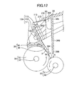
- the supply roller 37 opposes the developing roller 38 diagonally from the lower front side so that the top of the supply roller 37 is lower than the top edge of the lower portion of the partitioning wall 40.
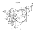
- the developing roller 38 is driven to rotate counterclockwise in Fig. 11 by a driving force inputted into the developing roller shaft 52 from a motor (not shown). Further, a developing bias is applied to the developing roller 38 during a developing operation.
- the free end 386 of the plate wall 349 is positioned lower than the contact part X at which the pressing part 55 of the thickness-regulating blade 39 contacts the developing roller 38.
Landscapes
- Physics & Mathematics (AREA)
- General Physics & Mathematics (AREA)
- Dry Development In Electrophotography (AREA)
- Electrophotography Configuration And Component (AREA)
Abstract
a holding part that is formed as a recess in an inner wall of the developer-accommodating chamber and rotatably holds the agitator shaft; a guiding groove that is open on one end and guides the agitator shaft toward the holding part; and a restricting part that restricts movement of the agitator shaft held in the holding part at a border between the guiding groove and the holding part. The guiding groove guiding the agitator shaft toward the restricting part from a position shallower in the inner wall of the developer-accommodating chamber than the holding part with respect to the recessed direction of the holding part.
Description
- The invention relates generally to an image-forming device, such as a laser printer, and more particularly, to a developer cartridge and process cartridge mounted in the image-forming device.
- Conventional electrophotographic image-forming devices such as laser printers that employ a nonmagnetic, single-component developing method generally include a photosensitive drum on which electrostatic latent images are formed, and a developer cartridge for tribocharging and supplying toner to the photosensitive drum in order to develop the electrostatic latent image formed thereon.
- One such developer cartridge disclosed in Japanese Patent Application Publication No.
2000-275948 - This type of developer cartridge also includes an agitator disposed in the toner-accommodating chamber for stirring toner therein. The toner stirred by the agitator is discharged toward the developing chamber through the hole formed in the partitioning wall. The supply roller supplies the discharged toner onto the developing roller while the toner is tribocharged between the two rollers. The thickness-regulating blade scrapes off excess charged toner carried on the developing roller so that the developing roller carries a thin layer on the surface thereof.
- A developing device disclosed in Japanese Patent Application Publication No.
2000-250296 - A developer cartridge disclosed in Japanese Patent Application Publication No.
2005-24811 - The above-described conventional developer cartridges have various disadvantages. One disadvantage is that the charged excess toner that the thickness-regulating blade scrapes off the surface of the developing roller accumulates in the developing chamber and sometimes returns to the toner-accommodating chamber. As the ratio of previously charged toner to uncharged toner increases, charge control becomes difficult when tribocharging the toner between the supply roller and the developing roller, leading to a decline in image quality. Therefore, it is desirable to supply as much of the toner that has been previously charged for development as quickly as possible.
- Another disadvantage is that the number of parts required for fixing the cleaning member to the agitator increases, making the assembly process more complex. Further, it is difficult to cleanly peel off the cleaning member from the agitator for recycling when the cleaning member has been fixed with double-sided tape.
- With the above-described structure for supporting the shaft of the agitator, there is a danger that the shaft could become damaged when sliding over the restricting part due to a large load being applied to the shaft when the shaft flexes.
- Still another disadvantage is that by forming the opening in the casing of the developer cartridge described above for exposing the developing roller, the peripheral edges of the opening are inevitably weaker. Hence, when the user grips the casing near the opening when mounting or removing the developer cartridge, the casing deforms (flexes), which may cause damage to the developing roller or force toner out through a gap formed between the developing roller and the casing.
- In view of the foregoing, it is an object of the invention to provide a developer cartridge capable of preventing a decline in image quality.
- It is another object of the invention to provide a developer cartridge having a cleaning member fixed to an agitating member through a simple construction.
- It is still another object of the invention to provide a developer cartridge that reduces the risk of damage to the shaft of the agitator when the agitator is mounted in the developer cartridge.
- It is yet another object of the invention to provide a developer cartridge having a casing that is reinforced along an opening therein and that reliably maintains a precise gap between the developing roller and an edge of the opening.
- It is another object of the invention to provide a process cartridge and an image-forming device in which the developer cartridge that attains at least one of the above-described objects is mounted.
- The above and other others will be attained by a developer cartridge including:
- a developer-accommodating chamber that accommodates developer;
- a developer-carrying member that carries developer;
- a supplying member that charges and supplies developer accommodated in the developer-accommodating chamber to the developer-carrying member;
- a thickness-regulating member that contacts the developer-carrying member at a contact part with pressure to regulate a thickness of developer carried on the developer-carrying member; and
- a wall having a base end and a distal end and disposed between the developer-accommodating chamber and the thickness-regulating member, the distal end of the wall being positioned closer to the supplying member than the base end of the wall, the wall partitioning the thickness-regulating member from the developer-accommodating chamber such that a distance between the supplying member and the distal end of the wall is shorter than a distance between the supplying member and the contact part at which the thickness-regulating member contacts the developer-carrying member.
- With this construction, the wall provided between the developer-accommodating chamber and the thickness-regulating member partitions the thickness-regulating member from the developer-accommodating chamber. The wall is disposed so that the distance between the supplying member and the distal end of the wall is shorter than the distance between the supplying member and the contact part at which the thickness-regulating member contacts the developer-carrying member. Therefore, when the thickness-regulating member scrapes excess developer off the developer-carrying member to regulate the thickness of developer carried on the developer-carrying member, this developer remains between the thickness-regulating member and the wall and can once again be supplied to the developer-carrying member and regulated by the pressing contact of the thickness-regulating member. As a result, since developer scraped off by the thickness-regulating member, that is, developer carrying a static charge, can be prevented from returning to the developer-accommodating chamber, it is possible to control the charge of the developer reliably in order to prevent a decline in image quality.
- The invention described above can reliably tribocharge the developer. Further, the supplying member can easily return previously charged developer to the developer-carrying member, while also easily supplying uncharged developer accommodated in the developer-accommodating chamber to the developer-carrying member.
- According to another aspect of the invention, there is provided a developer cartridge including:
- a developer-accommodating chamber that accommodates developer;
- at least one window that detects an amount of developer remaining in the developer-accommodating chamber;
- a cleaning member that cleans the window;
- an agitating member that stirs the developer accommodated in the developer-accommodating chamber; and
- a fixing member disposed on the agitating member and having a slit formed therein, the fixing member fixing the cleaning member when the cleaning member is inserted into the slit.
- With this construction, by inserting the cleaning member through the slit in the fixing member, the cleaning member is fixed to the agitating member via the fixing member. This construction eliminates the need for extra parts for fixing the cleaning member and agitating member, enabling the cleaning member to be fixed to the agitating member through a simple assembly process. Accordingly, the invention reduces the number of required parts and improves the efficiency of the assembly operation. Further, since the cleaning member is fixed to the fixing member by insertion through the slit, the cleaning member can also be easily removed, improving the suitability of the cleaning member for recycling.
- According to still another aspect of the invention, there is provided a developer cartridge including:
- a developer-accommodating chamber that accommodates developer;
- an agitator that has an agitator shaft and is disposed inside the developer-accommodating chamber; and
- a shaft support unit that supports at least one end of the agitator shaft, the shaft support unit comprising:
- a holding part that is formed as a recess in an inner wall of the developer-accommodating chamber and rotatably holds the agitator shaft;
- a guiding groove that is open on one end and guides the agitator shaft toward the holding part; and
- a restricting part that restricts movement of the agitator shaft held in the holding part at a border between the guiding groove and the holding part, the guiding groove guiding the agitator shaft toward the restricting part from a position shallower in the inner wall of the developer-accommodating chamber than the holding part with respect to the recessed direction of the holding part.
- Since the guiding groove guides the agitator shaft toward the restricting part from a position shallower in the inner wall than the holding part in the recessed direction, the agitator shaft requires less flexing to slide over the restricting part from the guiding groove when mounting the agitator in the developer cartridge, thereby reducing the load applied to the agitator shaft and decreasing the risk of damage to the agitator shaft. Further, since little force of resistance is applied against the agitator shaft sliding over the restricting part from the guiding groove, the agitator shaft can be easily mounted.
- According to yet another aspect of the invention, there is provided a developer cartridge including:
- a developer-carrying member having a peripheral surface on which developer is carried;
- a casing that has an opening formed therein and supports the developer-carrying member in an exposed position in the opening, the opening having an edge; and
- a reinforcing member that is substantially formed in a box-shape and is disposed along the edge of the opening for reinforcing the edge.
- This construction provides the casing with the box-shaped reinforcing part along the edges of the opening in which the developer-carrying member is exposed, thereby effectively reinforcing the edge of the opening, which portion of the casing has less strength. Further, since the reinforcing part is formed in a box shape, the thickness of the casing provided with the reinforcing part can be equivalent to the thickness of the casing in regions other than the reinforcing part, reducing the likelihood of sinks forming during the molding process in the surface opposing the developer-carrying member. Therefore, the opening of the casing can be reliably reinforced while maintaining a precise gap between the developer-carrying member and the edge of the opening.
- The construction described above prevents deformation of the casing when a user grips the casing near the opening, thereby effectively preventing damage to the developing roller and preventing developer from leaking through the gap formed between the developing roller and the casing.
- The particular features and advantages of present invention as well as other objects will become apparent from the following description taken in connection with the accompanying drawings, in which:
-
Fig. 1 is a side cross-sectional view of a laser printer serving as the image-forming device of the invention; -
Fig. 2A is a side cross-sectional view of a process cartridge employed in the laser printer shown inFig. 1 ; -
Fig. 2B is a side cross-sectional view of another process cartridge usable in the laser printer shown inFig. 1 in lieu of the process cartridge shown inFig. 2A ; -
Fig. 3 is a rear side perspective view of a developer cartridge according to the invention; -
Fig. 4 is a rear view of the developer cartridge; -
Fig. 5 is a side view of the developer cartridge; -
Fig. 6 is a bottom view of the developer cartridge; -
Fig. 7 is an enlarged side cross-sectional view showing a lower edge of an opening formed in the casing of the developer cartridge; -
Fig. 8 is an enlarged side cross-sectional view showing the lower edge of the opening formed in the casing of a conventional developer cartridge; -
Fig. 9 is an enlarged side cross-sectional view showing the lower edge of the opening formed in the casing ofFig. 7 according to a variation of the illustrative example; -
Fig. 10 is an enlarged side cross-sectional view showing the lower edge of the opening formed in the casing ofFig. 7 according to another variation of the illustrative example; -
Fig. 11 is a side cross-sectional view of a developing chamber employed in the laser printer ofFig. 1 ; -
Fig. 12 is an enlarged side cross-sectional view showing a portion of the developing chamber near a supply roller, developing roller, thickness-regulating blade, and plate wall; -
Fig. 13 is a cross-sectional view of the developer cartridge along a line A-A inFig. 11 ; -
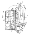
Fig. 14 is a perspective view from the front of the developer cartridge inFig. 11 with a top cover in an open state; -
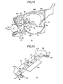
Fig. 15 is a side cross-sectional view of a developer cartridge employed in the laser printer ofFig. 1 ; -
Fig. 16 is a perspective view of an agitator in the developer cartridge; -
Fig. 17 is a plan view of the agitator; -
Fig. 18 is a cross-sectional view of a portion of the agitator indicated by the line B-B inFig. 17 ; -
Fig. 19 is a cross-sectional view of a portion of the agitator indicated by the line C-C inFig. 17 ; -
Fig. 20 is a perspective view showing an axial end of the agitator prior to mounting a wiper; -
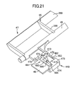
Fig. 21 is a perspective view showing the axial end of the agitator after mounting the wiper; -
Fig. 22 is a plan view showing the axial end of the agitator; -
Fig. 23 is a bottom view showing the axial end of the agitator; -
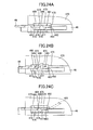
Fig. 24A is a cross-sectional view illustrating the process of assembling the wiper directly after the wiper is inserted into the slit; -
Fig. 24B is a cross-sectional view illustrating the process of assembling the wiper as the wiper is inserted farther into the slit; -
Fig. 24C is a cross-sectional view illustrating the process of assembling the wiper after the wiper has been completely inserted into the slit; -
Fig. 25A is a plan view of a wiper according to a variation of the illustrative example; -
Fig. 25B is a cross-sectional view showing the wiper ofFig. 25A mounted on a fixing member; -
Fig. 26 is a perspective view of the agitator provided with a guide plate according to a variation of the illustrative example; -
Fig. 27 is a perspective view inside a developer-accommodating chamber of the developer cartridge showing an agitator shaft that is held in a shaft support unit; -
Fig. 28 is a center cross-sectional view of the developer cartridge without the agitator; -
Fig. 29 is a perspective view showing the shaft support unit from inside the developer-accommodating chamber when the agitator shaft has been removed; and -
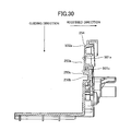
Fig. 30 is a cross-sectional view of the developer cartridge along a line D-D inFig. 28 . - A general structure of a laser printer will be described. As shown in
Fig. 1 , thelaser printer 1 serving as the image-forming device of the invention includes amain casing 2 and, within themain casing 2, a feeding unit 4 for supplying sheets of apaper 3, an image-formingunit 5 for forming images on thepaper 3 supplied by the feeding unit 4. - The
laser printer 1 also includes anaccess opening 6 formed in one side wall of themain casing 2 for inserting and removing aprocess cartridge 20 described later, and a front cover 7 capable of opening and closing over theaccess opening 6. The front cover 7 is rotatably supported by acover shaft 8 inserted through a bottom edge of the front cover 7. Accordingly, when the front cover 7 is rotated closed about thecover shaft 8, the front cover 7 covers theaccess opening 6, as shown inFig. 1 . When the front cover 7 is rotated open about thecover shaft 8, theaccess opening 6 is exposed, enabling theprocess cartridge 20 to be mounted into or removed from themain casing 2 via theaccess opening 6. - In the following description, the side of the
laser printer 1 on which the front cover 7 is mounted and the corresponding side of theprocess cartridge 20 when theprocess cartridge 20 is mounted in themain casing 2 will be referred to as the "front side," while the opposite side will be referred to as the "rear side." - The feeding unit 4 includes a
paper tray 9 that can be inserted into or removed from a lower section of themain casing 2 in the front-to-rear direction, a separatingroller 10 and a separating pad 11 disposed above a front end of thepaper tray 9, and a feedingroller 12 disposed on the rear side of the separatingroller 10 upstream of the separating pad 11 with respect to the conveying direction of the paper 3 (hereinafter referred to as the "paper-conveying direction"). The feeding unit 4 also includes apaper dust roller 13 disposed above and forward of the separatingroller 10 and downstream of the separatingroller 10 in the paper-conveying direction, and a pinch roller 14 disposed in opposition to thepaper dust roller 13. - A paper-conveying path for the
paper 3 on the feeding end reverses directions toward the rear side of thelaser printer 1, forming a substantial U-shape near thepaper dust roller 13. The feeding unit 4 also includes a pair ofregistration rollers 15 disposed below theprocess cartridge 20 farther downstream of the U-shaped portion of the paper-conveying path with respect to the paper-conveying direction. - A paper-pressing
plate 16 is provided inside thepaper tray 9 for supporting thepaper 3 in a stacked state. The paper-pressingplate 16 is pivotably supported on the rear end thereof, so that the front end can pivot downward to a resting position in which the paper-pressingplate 16 rests on a bottom plate of thepaper tray 9 and can pivot upward to a feeding position in which the paper-pressingplate 16 slopes upward from the rear end to the front end. - A
lever 17 is provided in the front section of thepaper tray 9 for lifting the front end of the paper-pressingplate 16 upward. The rear end of thelever 17 is pivotably supported on alever shaft 18 at a position below the front end of the paper-pressingplate 16 so that the front end of thelever 17 can pivot between a level position in which thelever 17 lies along the bottom plate of thepaper tray 9 and a sloped position in which the front end of thelever 17 lifts the paper-pressingplate 16 upward. When a driving force is inputted into thelever shaft 18, thelever 17 rotates about thelever shaft 18 and the front end of thelever 17 raises the front end of the paper-pressingplate 16, shifting the paper-pressingplate 16 into the feeding position. - When the paper-pressing
plate 16 is in the feeding position, the topmost sheet ofpaper 3 stacked on the paper-pressingplate 16 is pressed against the feedingroller 12. Therotating feeding roller 12 begins feeding the sheets ofpaper 3 toward a separating position between the separatingroller 10 and separating pad 11. - When the
paper tray 9 is removed from themain casing 2, the paper-pressingplate 16 settles into the resting position. While the paper-pressingplate 16 is in the resting position, thepaper 3 can be stacked on the paper-pressingplate 16. - When the feeding
roller 12 conveys a sheet of thepaper 3 toward the separating position and the sheet becomes interposed between the separatingroller 10 and separating pad 11, the rotating separatingroller 10 separates and feeds thepaper 3 one sheet at a time. Each sheet ofpaper 3 fed by the separatingroller 10 passes between thepaper dust roller 13 and pinch roller 14. After thepaper dust roller 13 removes paper dust from the sheet ofpaper 3, the sheet is conveyed along the U-shaped paper-conveying path on the feeding end, thereby reversing directions in themain casing 2, and is conveyed toward theregistration rollers 15. - After registering the
paper 3, theregistration rollers 15 convey thepaper 3 to a transfer position between aphotosensitive drum 28 and atransfer roller 31 described later, at which position a toner image formed on thephotosensitive drum 28 is transferred onto thepaper 3. - The image-forming
unit 5 includes ascanning unit 19, theprocess cartridge 20, and a fixingunit 21. - The
scanning unit 19 is disposed in a top section of themain casing 2 and includes a laser light source (not shown), apolygon mirror 22 that can be driven to rotate, anfθ lens 23, a reflectingmirror 24, alens 25, and a reflectingmirror 26. The laser light source emits a laser beam based on image data. As illustrated by a dotted line inFig. 1 , the laser beam is deflected by thepolygon mirror 22, passes through thefθ lens 23, is reflected by the reflectingmirror 24, passes through thelens 25, and is reflected downward by the reflectingmirror 26 to be irradiated on the surface of thephotosensitive drum 28 in theprocess cartridge 20. - As shown in
Fig. 2A , theprocess cartridge 20 is provided in themain casing 2 beneath thescanning unit 19 and can be mounted in or removed from themain casing 2 through theaccess opening 6. Theprocess cartridge 20 includes adrum cartridge 27 and adeveloper cartridge 30 detachably mounted on thedrum cartridge 27. - The
drum cartridge 27 includes adrum side casing 76 and, within thedrum side casing 76, thephotosensitive drum 28, aScorotron charger 29, thetransfer roller 31, and a cleaningmember 32. - Within the
drum cartridge 27 are formed apre-drum opening 113 for conveying thepaper 3 to the transfer position inside thedrum cartridge 27, and apost-drum opening 114 for conveying thepaper 3 from the transfer position back out of thedrum cartridge 27. Thepre-drum opening 113 is provided on the front side of the transfer position below thedeveloper cartridge 30 to allow communication between areas inside and outside thedrum cartridge 27 along an axial direction of the transfer roller 31 (hereinafter simply referred to as the "axial direction"). Thepost-drum opening 114 is formed on the rear side of the transfer position opposing thepre-drum opening 113 via the transfer position in order to provide communication between the inside and outside of thedrum cartridge 27 along the axial direction. - The
photosensitive drum 28 includes amain drum body 33 that is cylindrical in shape and has a positive charging photosensitive layer formed of polycarbonate or the like on its outer surface, and ametal drum shaft 34 extending through the center of themain drum body 33 along the axial direction thereof. Themetal drum shaft 34 is supported in thedrum cartridge 27, and themain drum body 33 is rotatably supported relative to themetal drum shaft 34. With this construction, thephotosensitive drum 28 is disposed in thedrum cartridge 27 and is capable of rotating about themetal drum shaft 34. Further, thephotosensitive drum 28 is driven to rotate by a driving force inputted from a motor (not shown). - The
charger 29 is supported on thedrum cartridge 27 diagonally above and rearward of thephotosensitive drum 28. Thecharger 29 opposes thephotosensitive drum 28 but is separated a prescribed distance from thephotosensitive drum 28 so as not to contact the same. Thecharger 29 includes adischarge wire 35 disposed in opposition to but separated a prescribed distance from thephotosensitive drum 28, and agrid 49 provided between thedischarge wire 35 and thephotosensitive drum 28 for controlling the amount of corona discharge from thedischarge wire 35 that reaches thephotosensitive drum 28. By applying a high voltage to thedischarge wire 35 for generating a corona discharge from thedischarge wire 35 at the same time a bias voltage is applied to thegrid 49, thecharger 29 can charge the surface of thephotosensitive drum 28 with a uniform positive polarity. - The
developer cartridge 30 includes acasing 36 and, within thecasing 36, asupply roller 37, a developingroller 38, and a thickness-regulatingblade 39. Thedeveloper cartridge 30 is detachably mounted on thedrum cartridge 27. Accordingly, when theprocess cartridge 20 is mounted in themain casing 2, thedeveloper cartridge 30 can be mounted in themain casing 2 by first opening the front cover 7 and subsequently inserting thedeveloper cartridge 30 through theaccess opening 6 and mounting thedeveloper cartridge 30 on theprocess cartridge 20. - The
casing 36 has a box shape that is open on the rear side, as will be described later, and has twoside walls 69. Apartitioning wall 40 is provided in thecasing 36 for partitioning the interior of thecasing 36 into a toner-accommodatingchamber 41 and a developingchamber 42. Thepartitioning wall 40 is disposed at a position in thecasing 36 midway in the front-to-rear direction for partitioning the interior of thecasing 36 in the front-to-rear direction. Anopening 43 is formed through a midway region of thepartitioning wall 40. - The toner-accommodating
chamber 41 occupies a space in the front side of thecasing 36 partitioned by thepartitioning wall 40. The toner-accommodatingchamber 41 is filled with a nonmagnetic, single-component toner having a positive charge. The toner used in the illustrative example is a polymerized toner obtained by copolymerizing a polymerized monomer using a well-known polymerization method such as suspension polymerization. The polymerized monomer may be, for example, a styrene monomer such as styrene or an acrylic monomer such as acrylic acid, alkyl (C1-C4) acrylate, or alkyl (C1-C4) meta acrylate. The polymerized toner is formed as particles substantially spherical in shape in order to have excellent fluidity for achieving high-quality image formation. - This type of toner is compounded with a coloring agent, such as carbon black, or wax, as well as an additive such as silica to improve fluidity. The average diameter of the toner particles is about 6-10 µm.
-
Toner detection windows 44 are provided in bothside walls 69 of thecasing 36 that define the toner-accommodatingchamber 41 for detecting the amount of toner remaining in the toner-accommodatingchamber 41. Thetoner detection windows 44 are formed in theside walls 69 near thepartitioning wall 40 and oppose each other in the width direction (the direction orthogonal to the front-to-rear direction and the vertical) across the toner-accommodatingchamber 41. Thetoner detection windows 44 are formed by embedding a transparent disc-shaped plate in eachside wall 69. - An
agitator 45 is disposed in the toner-accommodatingchamber 41 for agitating toner accommodated therein. Theagitator 45 includes arotational shaft 46 and an agitatingmember 47. - The
rotational shaft 46 is rotatably supported in theside walls 69 substantially in the center of the toner-accommodatingchamber 41. The agitatingmember 47 is provided on therotational shaft 46. A motor (not shown) produces a driving force that is inputted into therotational shaft 46 for driving therotational shaft 46 to rotate. Consequently, the agitatingmember 47 moves in a circular path about therotational shaft 46 through the toner-accommodatingchamber 41 and stirs toner accommodated in the toner-accommodatingchamber 41. When the agitatingmember 47 stirs the toner, some of the toner is discharged in the front-to-rear direction toward thesupply roller 37 through theopening 43 formed in thepartitioning plate 40. - The
agitator 45 also includeswipers 48 attached at both axial ends of therotational shaft 46. When therotational shaft 46 rotates, thewipers 48 move in a circular direction about therotational shaft 46 through the toner-accommodatingchamber 41 in order to wipe thetoner detection windows 44 provided in theside walls 69. Hence, thewipers 48 function to clean thetoner detection windows 44. - The developing
chamber 42 occupies an interior space in the rear side of thecasing 36 partitioned by thepartitioning wall 40. The developingchamber 42 accommodates thesupply roller 37, the developingroller 38, and the thickness-regulatingblade 39. - The
supply roller 37 is disposed rearward of theopening 43 and includes ametal roller shaft 50 covered by asponge roller 51 formed of an electrically conductive foam material. Theroller shaft 50 is rotatably supported within the developingchamber 42 in bothside walls 69 of thecasing 36. Thesupply roller 37 is driven to rotate by a driving force inputted into theroller shaft 50 from a motor (not shown). - The developing
roller 38 is disposed rearward of thesupply roller 37 and contacts thesupply roller 37 with pressure so that both are compressed. The developingroller 38 includes ametal roller shaft 52, and arubber roller 53 formed of an electrically conductive rubber material that covers theroller shaft 52. Theroller shaft 52 is rotatably supported in bothside walls 69 within the developingchamber 42. Therubber roller 53 is more specifically formed of an electrically conductive urethane rubber or silicon rubber containing fine carbon particles, the surface of which is coated with urethane rubber or silicon rubber containing fluorine. The developingroller 38 is driven to rotate by a driving force inputted into theroller shaft 52 from a motor (not shown). Further, a developing bias is applied to the developingroller 38 during a developing operation. - When the
developer cartridge 30 is mounted in thedrum cartridge 27, the developingroller 38 opposes thephotosensitive drum 28 diagonally from the top front thereof. In other words, the rear portion of the developingroller 38 below the vertical center that protrudes farthest rearward contacts thephotosensitive drum 28. - The thickness-regulating
blade 39 includes amain blade member 54 configured of a metal leaf spring, and apressing part 55 provided on a distal end of themain blade member 54. Thepressing part 55 has a semicircular cross section and is formed of an insulating silicon rubber. The thickness-regulatingblade 39 is attached to thecasing 36. Specifically, a mountingmember 109 is provided for fixing a base end of themain blade member 54 to a rear end portion of thecasing 36. - A sealing
member 110 is interposed between thecasing 36 and mountingmember 109 to prevent toner from leaking therethrough. - The mounting
member 109 is provided in the rear section of thecasing 36 and includes a plate-shapedfront support member 115, aback support member 111 having a substantially L-shaped cross section, and ascrew 112. Thefront support member 115 is disposed on the rear side of the sealingmember 110. The base end of themain blade member 54 is disposed on the rear side of thefront support member 115, and theback support member 111 is disposed on the rear side of the base end of themain blade member 54. Thescrew 112 is inserted through theback support member 111, the base end of themain blade member 54, and thefront support member 115 and fixes these components together. With the sealingmember 110 interposed between the thickness-regulatingblade 39 andcasing 36, the thickness-regulatingblade 39 is fixed together with the mountingmember 109 to thecasing 36 by a screw 130 (seeFigs. 3 and4 ). Hence, themain blade member 54 is attached to thecasing 36 with the base end of themain blade member 54 interposed between thefront support member 115 andback support member 111. With this construction, thepressing part 55 disposed on the distal end of themain blade member 54 contacts the developingroller 38 with pressure through the elastic force of themain blade member 54. - Toner discharged through the
opening 43 is supplied onto the developingroller 38 by therotating supply roller 37. At this time, the toner is positively tribocharged between thesupply roller 37 and the developingroller 38. As the developingroller 38 rotates, the toner supplied to the surface of the developingroller 38 passes between therubber roller 53 of the developingroller 38 and thepressing part 55 of the thickness-regulatingblade 39, thereby maintaining a uniform thickness of toner on the surface of the developingroller 38. - The cleaning
member 32 includes a cleaningbrush 58 that functions to scrape off paper dust and the like deposited on thephotosensitive drum 28. - As the
photosensitive drum 28 rotates, thecharger 29 charges the surface of thephotosensitive drum 28 with a uniform positive polarity. Subsequently, a laser beam emitted from thescanning unit 19 is scanned at a high speed over the surface of thephotosensitive drum 28, forming an electrostatic latent image corresponding to an image to be formed on thepaper 3. - Next, positively charged toner carried on the surface of the developing
roller 38 comes into contact with thephotosensitive drum 28 as the developingroller 38 rotates and is supplied to areas on the surface of the positively chargedphotosensitive drum 28 that were exposed to the laser beam and, therefore, have a lower potential. In this way, the latent image on thephotosensitive drum 28 is transformed into a visible image according to a reverse developing process so that a toner image is carried on the surface of thephotosensitive drum 28. - Subsequently, as the
registration rollers 15 convey a sheet of thepaper 3 into thedrum cartridge 27 via thepre-drum opening 113 and through the transfer position between thephotosensitive drum 28 andtransfer roller 31, the toner image carried on the surface of the surface of thephotosensitive drum 28 is transferred onto thepaper 3 by the transfer bias applied to thetransfer roller 31. After the toner image is transferred, thepaper 3 is conveyed out of thedrum cartridge 27 via thepost-drum opening 114 and is conveyed to the fixingunit 21. - Toner remaining on the
photosensitive drum 28 after the transfer operation is recovered by the developingroller 38. Further, paper dust deposited on thephotosensitive drum 28 from thepaper 3 is recovered by the cleaningbrush 58 of the cleaningmember 32. - The fixing
unit 21 is disposed on the rear side of theprocess cartridge 20 and includes a fixedframe 59; and aheating roller 60 and apressure roller 61 provided within the fixedframe 59. - The
heating roller 60 includes a metal tube, the surface of which has been coated with a fluorine resin, and a halogen lamp disposed inside the metal tube for heating the same. Theheating roller 60 is driven to rotate by a driving force inputted from a motor (not shown). - The
pressure roller 61 is disposed below and in opposition to theheating roller 60 and contacts theheating roller 60 with pressure. Thepressure roller 61 is configured of a metal roller shaft covered with a roller that is formed of a rubber material. Thepressure roller 61 follows the rotational drive of theheating roller 60. - In the fixing
unit 21, a toner image transferred onto thepaper 3 at the transfer position is fixed to thepaper 3 by heat as thepaper 3 passes between theheating roller 60 andpressure roller 61. After the toner image is fixed to thepaper 3, theheating roller 60 andpressure roller 61 continue to convey thepaper 3 along a discharge end paper-conveying path toward adischarge tray 62 formed on the top surface of themain casing 2. - The paper-conveying path on the discharge end leads from the fixing
unit 21 to thedischarge tray 62 and is substantially U-shaped for reversing the conveying direction of thepaper 3 to a direction toward the front of thelaser printer 1. A pair of conveyingrollers 63 is disposed at a midpoint along the discharge end paper-conveying path, and a pair ofdischarge rollers 64 is disposed at a downstream end of the same path. - Hence, after passing through the fixing
unit 21, thepaper 3 is conveyed along the discharge end paper-conveying path, where the conveyingrollers 63 receive and convey thepaper 3 to thedischarge rollers 64, and thedischarge rollers 64 subsequently receive and discharge thepaper 3 onto thedischarge tray 62. - Next, a structure related to the casing of the developer cartridge will be described.
- As shown in
Figs. 2A and3 , thecasing 36 of thedeveloper cartridge 30 has a box shape that is open on the rear side and is integrally provided with atop wall 70, afront wall 72, the twoside walls 69 described above, and abottom wall 71. The open region on the rear side is anopening 94. - As shown in
Fig. 3 , theopening 94 is defined by theback support member 111 of the mountingmember 109, the rear edges of theside walls 69, and the rear edge of thebottom wall 71. When viewed from the rear side, theopening 94 is substantially rectangular and extends in the width direction. The developingroller 38 is disposed in theopening 94 and is exposed therefrom. As shown inFig. 5 , the developingroller 38 is supported on thecasing 36 so as to protrude out of thecasing 36 via theopening 94 when viewed from the side. Aninsertion hole 121 is formed in the rear end of eachside wall 69 of thecasing 36 at positions opposing each other in the width direction. Theroller shaft 52 of the developingroller 38 is inserted through the insertion holes 121 so that the developingroller 38 is rotatably supported on thecasing 36 with a vertical center portion of therubber roller 53 protruding farthest out of thecasing 36 through theopening 94. - As shown in
Fig. 2A , thetop wall 70 is plate-shaped in a plan view and functions to close off the top of the toner-accommodatingchamber 41 and developingchamber 42. - The
front wall 72 is plate-shaped in a front view and functions to close off the front side of the toner-accommodatingchamber 41. Thefront wall 72 extends downward from the front edge of thetop wall 70. - As shown in
Figs. 3 and5 , theside walls 69 are plate-shaped and function to close off the sides of the toner-accommodatingchamber 41 and developingchamber 42. Theside walls 69 also rotatably support therotational shaft 46,roller shaft 50, androller shaft 52. - As shown in
Fig. 2A , thebottom wall 71 functions to close off the bottom of the toner-accommodatingchamber 41 and developingchamber 42. Thebottom wall 71 is integrally provided with afront bottom wall 74, a centerbottom wall 75, and arear bottom wall 376. - The
front bottom wall 74 has a substantially semicircular cross section following the rotational path of theagitator 45 in the toner-accommodatingchamber 41. The centerbottom wall 75 is provided on the rear side of thefront bottom wall 74 and has a substantially semicircular cross section that follows the peripheral surface of thesupply roller 37 in the developingchamber 42. - The
rear bottom wall 376 is provided on the rear side of the centerbottom wall 75 and has a flanged plate shape that slopes downward to the rear. The rear edge of therear bottom wall 376 is alower edge 68 that forms the lower edge of theopening 94 extending in the width direction of thecasing 36. - A
handle 77 is provided on the front side of thecasing 36 for the user to grip when mounting or removing thedeveloper cartridge 30 andprocess cartridge 20. Thehandle 77 protrudes forward from the top of thefront wall 72 constituting thecasing 36. - As shown in
Fig. 3 , a gear mechanism (not shown) for driving therotational shaft 46,roller shaft 50, androller shaft 52 to rotate, and agear cover 79 for covering the gear mechanism are provided on one of theside walls 69 constituting thecasing 36. Two partialrear walls 73 are provided on thelower edge 68 in theopening 94 of thecasing 36. - The partial
rear walls 73 are disposed at the widthwise ends of thelower edge 68 and are spaced apart in the width direction. The partialrear walls 73 extend upward from both widthwise ends of thelower edge 68. A bottom portion of each partialrear walls 73 on the widthwise inner side has been cut away to form a substantial L-shape in a rear view. - A reinforcing
part 80 is provided on thelower edge 68 of theopening 94. - The reinforcing
part 80 extends along thelower edge 68 between the two partialrear walls 73 and is fitted in the cutout portions of the partialrear walls 73. The reinforcingpart 80 is formed continuously from thelower edge 68 of theopening 94 and is integrally provided with atop wall 82, afront wall 85, abottom wall 83, and twoside walls 84. The reinforcingpart 80 is box-shaped and open on the rear side. Specifically, a cross section of the reinforcingpart 80 taken orthogonal to the width direction substantially forms three sides of a rectangle with the missing side on the rear. - As shown in
Figs. 3 and7 , thetop wall 82 is provided along thelower edge 68 and formed continuously therewith. Thetop wall 82 protrudes rearward. Thefront wall 85 is shaped substantially like an elongated rectangular plate along thelower edge 68 and extends downward from the front edge of thetop wall 82. Thebottom wall 83 also has a substantially elongated rectangular plate shape extending along thelower edge 68 and is disposed opposite thetop wall 82 in the vertical direction. Thebottom wall 83 extends obliquely downward and rearward from the lower edge of thefront wall 85. - As shown in
Fig. 3 , theside walls 84 have a substantially rectangular plate shape and are disposed on both widthwise ends of thetop wall 82,front wall 85, andbottom wall 83 so as to face each other in the width direction. - As shown in
Fig. 7 , with thefront wall 85 linking the front ends of thetop wall 82 andbottom wall 83, a cross section of the reinforcingpart 80 taken orthogonal to the width direction forms three sides of a rectangle that opens toward the rear. Further, as shown inFig. 3 , the twoside walls 84 connect both widthwise edges of thetop wall 82 to the respective widthwise edges of thefront wall 85 andbottom wall 83, forming a box shape that opens toward the rear. - As shown in
Fig. 7 , the portion of thelower edge 68 above the reinforcingpart 80 is integrally provided with arear step part 97 and afront step part 98 disposed diagonally above and forward of therear step part 97. With this structure, a cross section of thelower edge 68 taken orthogonal to the width direction has a stepped formation. - The
rear step part 97 includes arear surface 99 and atop surface 100. Therear surface 99 forms the endface on the rear side of thetop wall 82. Therear surface 99 is a flat vertical surface in a cross section taken orthogonal to the width direction. Thetop surface 100 is provided continuously from the top of therear surface 99. In a cross section taken orthogonal to the width direction, thetop surface 100 has a flat plate shape extending diagonally upward and forward from therear surface 99. - The
front step part 98 includes arear surface 101, and atop surface 102. Therear surface 101 is formed continuously from the front edge of thetop surface 100. In a cross section taken orthogonal to the width direction, therear surface 101 is plate-shaped and extends diagonally upward and rearward from the front edge of thetop surface 100. - The
top surface 102 is formed continuously from the top edge of therear surface 101. In a cross section taken orthogonal to the width direction, thetop surface 102 has a plate shape that extends diagonally upward and forward from the top edge of therear surface 101. - A
lower film 87 is provided on thetop surface 102 of thelower edge 68. Thelower film 87 is formed of a polyethylene terephthalate film in the shape of a substantially rectangular sheet. As shown inFigs. 2 and7 , the rear half of thelower film 87 is fixed to the surface of thetop surface 102. - Specifically, the
lower film 87 is disposed so that the rear edge of thelower film 87 is flush with therear surface 101 of thelower edge 68, as shown inFig. 7 . More specifically, using the rear edge of the top surface 102 (the edge formed by therear surface 101 and top surface 102) as a reference for the front-to-rear direction, the rear half of thelower film 87 is fixed to thetop surface 102 with double-sided tape or the like (not shown). As a result, the rear endface of thelower film 87 is positioned flush with the reference in the front-to-rear direction. - As shown in
Fig. 2A , thelower film 87 is positioned with the rear half fixed to thetop surface 102 and the front half extending obliquely upward and forward to contact the lower surface of the developingroller 38. In this way, thelower film 87 blocks off the gap between thelower edge 68 and the developingroller 38 and prevents toner from leaking through that gap. - As shown in
Figs. 3 and6 , guidemembers 81 are provided on thecasing 36 of thedeveloper cartridge 30. Theguide members 81 protrude downward from thebottom wall 71 and are plate-shaped, extending in the front-to-rear direction. Theguide members 81 are disposed parallel to each other at intervals in the width direction. As shown inFig. 2A , eachguide member 81 protrudes downward from therear bottom wall 376 and centerbottom wall 75 and has arear end 105 connected to thefront wall 85 andbottom wall 83, and afront end 104 connected to thefront bottom wall 74. Eachguide member 81 is integrally formed with thebottom wall 83,front wall 85,rear bottom wall 376, centerbottom wall 75, andfront bottom wall 74. Eachguide member 81 also has alower edge 106 that extends straight forward from the rear end of thebottom wall 83 and then gently curves upward and forward below the centerbottom wall 75 to meet the rear end of thefront bottom wall 74. - As shown in
Fig. 3 , a guidemember reinforcing part 86 is provided for reinforcing theguide members 81. As shown inFigs. 2A and6 , the guidemember reinforcing part 86 has a plate shape and extends in the width direction. The guidemember reinforcing part 86 protrudes downward from the centerbottom wall 75 so as to intersect a front-to-rear midpoint of eachguide member 81 in a direction substantially orthogonal to the front-to-rear direction. The guidemember reinforcing part 86 couples theguide members 81 in the width direction and reinforces theguide members 81. - In the
developer cartridge 30 of the above-described illustrative example, the box-shaped reinforcingpart 80 open on the rear is provided along thelower edge 68 of theopening 94. The reinforcingpart 80 effectively reinforces thelower edge 68 of theopening 94, which is a weak region of thecasing 36. By forming the reinforcingpart 80 in a box shape open toward the rear side, it is possible to form thecasing 36 at a uniform thickness in the region of the reinforcingpart 80 and in the regions other than the reinforcingpart 80 to reduce the likelihood of sinks developing during molding in the surface opposing the developingroller 38 that is formed continuously with the reinforcingpart 80, that is, thetop surface 102 of thelower edge 68. Hence, the reinforcingpart 80 can reliably reinforce theopening 94 of thecasing 36 and, moreover, can maintain a precise gap between the developingroller 38 and thelower edge 68 of theopening 94. - In the
developer cartridge 30 of the illustrative example described above, the cross section of the reinforcingpart 80 taken orthogonal to the width direction has a three-sided rectangular shape, facilitating removal of the reinforcingpart 80 during the molding process and enabling the reinforcingpart 80 to be easily formed in a box shape. Hence, it is possible to reliably reinforce theopening 94 of thecasing 36, while simplifying the molding process. - In the
developer cartridge 30 of the illustrative example, the reinforcingpart 80 extends in the width direction of the developingroller 38, that is, along the width direction of thecasing 36 in thelower edge 68 of theopening 94. The reinforcingpart 80 prevents thecasing 36 from deforming when the user grips thecasing 36 near theopening 94, thereby effectively preventing damage to the developingroller 38 and the occurrence of toner leaking between the developingroller 38 andcasing 36. - The
lower film 87 in thedeveloper cartridge 30 of the illustrative example blocks off the gap formed between thelower edge 68 of theopening 94 and the developingroller 38, preventing toner from leaking through this gap. Further, the reinforcingpart 80 provided on thelower edge 68 is formed in a box shape that makes sinks less likely to occur during molding in thetop surface 102 of thelower edge 68 that opposes the developingroller 38. As a result, thetop surface 102 can be formed as a smooth surface, enabling thelower film 87 to be fixed to the smoothtop surface 102 with precision. - When the
lower edge 68 is formed with a simple rectangular cross section, as in the conventional structure shown inFig. 8 , if thelower film 87 is fixed to thelower edge 68 by aligning the rear edge of thelower film 87 with the rear edge of thelower edge 68, as shown by the solid line inFig. 8 , thelower film 87 is susceptible to peeling off thelower edge 68 should thelower edge 68 contact another component. On the other hand, if thelower film 87 is fixed to a position on thelower edge 68 farther forward than the rear edge, as indicated by the dotted line inFig. 8 , it is possible to reduce the risk of thelower film 87 peeling from the top surface of thelower edge 68, but there is no definite reference point for fixing thelower film 87 to thelower edge 68. As a result, it is not possible to fix thelower film 87 reliably to thelower edge 68 along the width direction, reducing the mounting precision of thelower film 87. - However, in the
developer cartridge 30 of the illustrative example, thelower edge 68 has a stepped cross-sectional shape configured of therear step part 97 andfront step part 98. Thelower film 87 is fixed to thelower edge 68 by aligning the rear edge of thelower film 87 with the rear edge of thefront step part 98 provided farther forward of therear step part 97, that is, on the upstream side in the direction that toner leaks through theopening 94. Therefore, if therear step part 97 contacts another component, thelower film 87 is less likely to peel of thetop surface 102 since thelower film 87 is fixed to thefront step part 98 disposed in front of therear step part 97. Moreover, fixing thelower film 87 on thefront step part 98 with the rear edge of thefront step part 98 as a reference point enables thelower film 87 to be fixed reliably along thetop surface 102. - In the
developer cartridge 30 of the illustrative example, the developingroller 38 protrudes out of thecasing 36 via theopening 94. Accordingly, when thedeveloper cartridge 30 is mounted on thedrum cartridge 27, the developingroller 38 can oppose thephotosensitive drum 28 from a position on the top front side so that a portion of the developingroller 38 below the vertical center protruding farthest through the opening 94 contacts thephotosensitive drum 28. This construction can enhance the freedom of setting the device layout, enabling production of a more compact device. The construction can also allocate space for forming the reinforcingpart 80 on thelower edge 68. - In the
developer cartridge 30 of the illustrative example, theguide members 81 are formed continuously with the reinforcingpart 80 for guiding thepaper 3 to the transfer position between thephotosensitive drum 28 andtransfer roller 31 when thepaper 3 is conveyed into thedrum cartridge 27 through thepre-drum opening 113. Accordingly, theguide members 81 can smoothly guide thepaper 3 to the transfer position, while further reinforcing theopening 94 of thecasing 36. - Further, the
guide members 81 are formed along the front-to-rear direction orthogonal to the width direction in which the reinforcingpart 80 extends. Theguide members 81 are spaced at intervals in the width direction. Accordingly, theguide members 81 can reliably guide thepaper 3 to the transfer position while reducing the frictional resistance generated between thepaper 3 and theguide members 81. - The
process cartridge 20 and thelaser printer 1 of the illustrative example described above includes thedeveloper cartridge 30 provided with the reinforcingpart 80 for reinforcing theopening 94 formed in thecasing 36. Accordingly, thedeveloper cartridge 30 enhances the rigidity of both theprocess cartridge 20 and thelaser printer 1. - In the illustrative example described above, the
developer cartridge 30 is detachably mounted on thedrum cartridge 27 to form theprocess cartridge 20, and theprocess cartridge 20 is detachably mounted in themain casing 2. However, it is also possible to provide thephotosensitive drum 28,charger 29,transfer roller 31, cleaningmember 32, and the like in themain casing 2, while eliminating thedrum cartridge 27, and to detachably mount thedeveloper cartridge 30 in themain casing 2. - In the illustrative example described above, the cross section of the reinforcing
part 80 taken orthogonal to the width direction forms three sides of a rectangle that is open toward the rear, as shown inFig. 7 . However, the reinforcing part of the invention need not have this cross-sectional shape, provided that the reinforcing part has a box shape. For example, the rear edges of thetop wall 82,bottom wall 83, and side walls 84 (not shown inFig. 9 ) may be connected by arear wall 95, as shown inFig. 9 . With this construction, the cross section of the reinforcing part taken orthogonal to the width direction is a closed, hollow rectangle. - Alternatively, the reinforcing
part 80 may be formed by connecting the front edges of thetop wall 82 andbottom wall 83, as shown inFig. 10 , so that the cross section of the reinforcing part taken orthogonal to the width direction forms a V-shape that opens rearward. - As shown in
Fig. 1 , thedeveloper cartridge 30 is detachably mounted in thedrum side casing 76. Accordingly, when theprocess cartridge 20 is mounted in themain casing 2, thedeveloper cartridge 30 can be mounted in themain casing 2 by first opening the front cover 7 and subsequently inserting thedeveloper cartridge 30 through theaccess opening 6 and mounting thedeveloper cartridge 30 on theprocess cartridge 20. - As shown in
Fig. 11 , thedeveloper cartridge 30 includes adeveloper side casing 36 and, within thedeveloper side casing 36, a developingroller 38, asupply roller 37, a thickness-regulatingblade 39, and aplate wall 349. - As shown in
Figs. 11 and14 , thedeveloper side casing 36 is formed in a box shape that is open on the rear side. Thedeveloper side casing 36 includes atop cover 370, and amain casing body 387. An open portion formed on the rear side is arear opening 94. - The
rear opening 94 is defined by aback support member 111 of a mountingmember 109 described later, and rear edges ofside walls 69 and abottom wall 71. Therear opening 94 is substantially rectangular in a rear view and extends in the width direction (hereinafter, the width direction will signify a direction orthogonal to the front-to-rear direction and the vertical direction). - The
top cover 370 is plate-shaped in a plan view and opens and closes over the top of a toner-accommodatingchamber 41 and a developingchamber 42 described later. Thetop cover 370 is integrally formed with an upper portion of apartitioning wall 40 described later, theplate wall 349, and a plurality of front-to-rear ribs 88 and widthwiseribs 89 described later. - The front-to-rear ribs 88 are plate-shaped and parallel to one another, extending in the front-to-rear direction on the
top cover 370 when thetop cover 370 is assembled on the main casing body 387 (seeFig. 11 ). As shown inFig. 14 , the front-to-rear ribs 88 are arranged parallel to one another at intervals in the width direction on the lower surface of thetop cover 370 opposing the interior of thedeveloper side casing 36. Forward protrudingparts 90 are disposed on front ends of two of the front-to-rear ribs 88 that are disposed nearest the widthwise center of thetop cover 370 for approaching the front edge of thetop cover 370. - Two of the front-to-rear ribs 88 nearest the widthwise ends of the
top cover 370 are also provided withstep parts 91 midway in the front-to-rear direction. Rearward protrudingparts 93 approaching the rear edge of thetop cover 370 are provided on the rear end of thesestep parts 91, forming a narrow stepped configuration along the front-to-rear direction. Further, laterally protrudingparts 300 are formed on the front-to-rear ribs 88 nearest the widthwise edges of thetop cover 370 protruding outward in the width direction from the narrow stepped configuration. - The
widthwise ribs 89 are plate-shaped and parallel to one another, extending in the width direction on thetop cover 370 when thetop cover 370 is assembled onto the main casing body 387 (seeFig. 11 ). As shown inFig. 14 , the parallel widthwiseribs 89 are arranged at intervals in the front-to-rear direction on the lower surface of thetop cover 370 facing the interior of thedeveloper side casing 36 so as to intersect the front-to-rear ribs 88. - The
main casing body 387 is integrally provided with afront wall 72, the twoside walls 69, thebottom wall 71, and a blade-mountingpart 373. Atop opening 395 that thetop cover 370 covers is formed in the top of themain casing body 387. - The
front wall 72 is plate-shaped in a front view and functions to close off the front side of the toner-accommodatingchamber 41. As shown inFig. 11 , thefront wall 72 extends downward from the front edge of thetop cover 370. - The
side walls 69 are plate-shaped and function to close off the sides of the toner-accommodatingchamber 41 and developingchamber 42. Theside walls 69 also rotatably support an agitatorrotational shaft 46, asupply roller shaft 50, and a developingroller shaft 52 described later. - The
bottom wall 71 functions to close off the bottom of the toner-accommodatingchamber 41 and developingchamber 42. Thebottom wall 71 is integrally provided with afront bottom wall 377, a center bottom wall 78, and a rear bottom wall 379. - The
front bottom wall 377 has a substantially semicircular cross section following the rotational path of anagitator 45 described later in the toner-accommodatingchamber 41. - The center bottom wall 78 is provided on the rear side of the
front bottom wall 377 and has a substantially semicircular cross section that follows the peripheral surface of thesupply roller 37 in the developingchamber 42. - The rear bottom wall 379 is provided on the rear side of the
front bottom wall 377 and has a flanged plate shape that slopes downward to the rear. - The blade-mounting
part 373 extends in the width direction, spanning between upper rear edges of theside walls 69. The blade-mountingpart 373 has a triangular cross section that narrows toward the bottom. The rear face of the blade-mountingpart 373 slopes downward and forward. - When viewed from the top, the
top opening 395 is shaped similar to the outer edges of a lattice formed by the intersecting front-to-rear ribs 88 and widthwiseribs 89 on thetop cover 370 so as to fit over these outer edges. Stepparts 96 are formed on bothside walls 69 constituting the sides of thetop opening 395 for fitting loosely with thestep parts 91 of the two front-to-rear ribs 88 nearest the outer widthwise edges of thetop cover 370 when thetop cover 370 is assembled on themain casing body 387. - As shown in
Figs. 11 and14 , hook parts formed by the rear edge of thetop cover 370 and each of the rearward protrudingparts 93 can engage with edges of the blade-mountingpart 373 on the widthwise ends formed of the top surface and front surface of the blade-mountingpart 373 and having an L-shaped cross section to position the rear edge of thetop cover 370 relative to the rear edge of themain casing body 387 when assembled. Thetop cover 370 is then rotated in the direction of the arrow inFig. 14 about the points of engagement between the hook parts and the edge of the blade-mountingpart 373 until the outer edges of the lattice formed by the intersecting front-to-rear ribs 88 and widthwiseribs 89 are fitted into thetop opening 395 formed in themain casing body 387, thereby completing the process of assembling thetop cover 370 on themain casing body 387. - By placing the rearward protruding
parts 93 in contact with the blade-mountingpart 373 during this assembly process, thetop cover 370 can be positioned relative to themain casing body 387 on the rear edge. Further, thetop cover 370 can be positioned relative to themain casing body 387 in the width direction when the laterally protrudingparts 300 provided on the outermost front-to-rear ribs 88 in the width direction contact the inner surfaces of theside walls 69 constituting themain casing body 387. The forward protrudingparts 90 provided on front edges of the two centermost front-to-rear ribs 88 then contact the inner surface of thefront wall 72 constituting themain casing body 387 to position thetop cover 370 relative to themain casing body 387 on the front side. As a result, thetop cover 370 can be assembled on themain casing body 387 with no play between the two. - A
handle 380 is provided on the front side of thedeveloper side casing 36 for the user to grip when mounting or removing thedeveloper cartridge 30 andprocess cartridge 20. Thehandle 380 protrudes forward from the top of thefront wall 72 constituting thedeveloper side casing 36. - A
gear mechanism 381 for driving the agitatorrotational shaft 46,supply roller shaft 50, and developingroller shaft 52 to rotate, and agear cover 382 for covering thegear mechanism 381 are provided on one of theside walls 69 constituting thedeveloper side casing 36. - The
partitioning wall 40 is provided in thedeveloper side casing 36 for partitioning the interior of thedeveloper side casing 36 into the toner-accommodatingchamber 41 and the developingchamber 42. - The
partitioning wall 40 is disposed at a position in thedeveloper side casing 36 midway in the front-to-rear direction for partitioning the interior of thedeveloper side casing 36 in the front-to-rear direction. Anopening 43 penetrates a midway region of thepartitioning wall 40 to allow communication between the toner-accommodatingchamber 41 and developingchamber 42. The lower portion of thepartitioning wall 40 is formed from the connecting parts of thefront bottom wall 377 and center bottom wall 78. The upper portion of thepartitioning wall 40 is formed on thetop cover 370 in the width direction so as to oppose the lower portion of thepartitioning wall 40 vertically with theopening 43 formed therebetween. Thepartitioning wall 40 extends vertically downward from thetop cover 370 with a base end of thepartitioning wall 40 connected to thetop cover 370 at a position in the front-to-rear direction of thetop cover 370 substantially equivalent to thestep parts 91. - As shown in
Fig. 11 , the toner-accommodatingchamber 41 occupies a space in the front side of thecasing 36 partitioned by thepartitioning wall 40. The toner-accommodatingchamber 41 is filled with a nonmagnetic, single-component toner having a positive charge. - Toner supply openings for filling the toner-accommodating
chamber 41 with toner are formed in bothside walls 69 of thedeveloper side casing 36 that define the toner-accommodatingchamber 41. The toner supply openings are sealed withcaps 335. -
Toner detection windows 44 are provided in bothside walls 69 of thecasing 36 that define the toner-accommodatingchamber 41 for detecting the amount of toner remaining in the toner-accommodatingchamber 41. Thetoner detection windows 44 are formed in theside walls 69 near thepartitioning wall 40 and oppose each other in the width direction across the toner-accommodatingchamber 41. Thetoner detection windows 44 are formed by embedding a transparent disc-shaped plate in eachside wall 69. - An
agitator 45 is disposed in the toner-accommodatingchamber 41 for agitating toner accommodated therein. Theagitator 45 includes arotational shaft 46 and an agitatingmember 47. Therotational shaft 46 is rotatably supported in theside walls 69 substantially in the center of the toner-accommodatingchamber 41. The agitatingmember 47 is provided on therotational shaft 46. A motor (not shown) produces a driving force that is inputted into therotational shaft 46 for driving therotational shaft 46 to rotate. - The
agitator 45 also includeswipers 48 attached at both axial ends of therotational shaft 46. When therotational shaft 46 rotates, thewipers 48 move in a circular direction about therotational shaft 46 through the toner-accommodatingchamber 41 in order to wipe thetoner detection windows 44 provided in theside walls 69. Hence, thewipers 48 function to clean thetoner detection windows 44. - The developing
chamber 42 occupies an interior space in the rear side of thecasing 36 partitioned by thepartitioning wall 40. The developingchamber 42 accommodates thesupply roller 37, the developingroller 38, and the thickness-regulatingblade 39 and is provided with theplate wall 349. - The
supply roller 37 is disposed rearward of theopening 43 above the center bottom wall 78 of the developingchamber 42. Thesupply roller 37 opposes the developingroller 38 diagonally from the lower front side so that the top of thesupply roller 37 is lower than the top edge of the lower portion of thepartitioning wall 40. - The
supply roller 37 includes ametal roller shaft 50 covered by asponge roller 51 formed of an electrically conductive foam material. Thesupply roller 37 is supported in theside walls 69 of thedeveloper side casing 36 in contact with the developingroller 38 so that both are compressed to a degree. Specifically, through-holes 122 are provided in each of theside walls 69 at positions opposing each other in the width direction. Thesupply roller shaft 50 is inserted into the through-holes 122 so that thesupply roller 37 is rotatably supported in thedeveloper side casing 36. - A driving force from a motor (not shown) is inputted into the
supply roller shaft 50 for driving thesupply roller 37 to rotate. Thesupply roller 37 rotates counterclockwise inFig. 11 so that the peripheral surface of thesupply roller 37 moves in the opposite direction of the developingroller 38 at the point of contact between the two rollers. - The developing
roller 38 is disposed above the rear bottom wall 379 of the developingchamber 42 on the opposite side of thesupply roller 37 from the toner-accommodatingchamber 41 in the front-to-rear direction, that is, rearward of thesupply roller 37. The developingroller 38 opposes thesupply roller 37 diagonally from the upper rear side and contacts thesupply roller 37 with pressure. - The developing
roller 38 is disposed so that substantially the upper half of the developingroller 38 is above the top of thesupply roller 37. The developingroller 38 has a larger diameter than thesupply roller 37 and includes the metal developingroller shaft 52 mentioned above, and arubber roller 53 formed of an electrically conductive rubber material that covers the developingroller shaft 52. Therubber roller 53 is more specifically formed of an electrically conductive urethane rubber or silicon rubber containing fine carbon particles or the like, the surface of which is coated with urethane rubber or silicon rubber containing fluorine. The developingroller shaft 52 is supported in theside walls 69 of thedeveloper side casing 36 within the developingchamber 42. - The developing
roller 38 is supported in theside walls 69 so as to protrude out of thedeveloper side casing 36 through therear opening 94. More specifically, through-holes 121 are formed in bothside walls 69 of thedeveloper side casing 36 at positions near the rear end thereof so as to oppose each other in the width direction. The developingroller shaft 52 is inserted through the through-holes 121 so that the developingroller 38 is rotatably supported in thedeveloper side casing 36 with a vertical center portion of therubber roller 53 protruding farthest out of thedeveloper side casing 36 through therear opening 94. - The developing
roller 38 is driven to rotate counterclockwise inFig. 11 by a driving force inputted into the developingroller shaft 52 from a motor (not shown). Further, a developing bias is applied to the developingroller 38 during a developing operation. - The thickness-regulating
blade 39 is disposed in the developingchamber 42 above the developingroller 38 and rearward of theplate wall 349 described later. The blade-mountingpart 373 supported on the rear side of theside walls 69 holds the thickness-regulatingblade 39 at both widthwise ends thereof. - The thickness-regulating
blade 39 includes amain blade member 54 configured of a metal leaf spring that is rectangular in a front view (seeFig. 13 ), and apressing part 55 provided on a distal end of themain blade member 54. Themain blade member 54 includes anupper end 383, which is a base end mounted in the blade-mountingpart 373, and alower end 384, which is the distal end on which thepressing part 55 is provided. Thepressing part 55 has a semicircular cross section and is formed of an insulating silicon rubber. - As shown in
Fig. 13 , the thickness-regulatingblade 39 extends in the width direction along the rear face of the blade-mountingpart 373. As shown inFig. 11 , the mountingmember 109 fixes theupper end 383 of themain blade member 54 to the rear face of the blade-mountingpart 373 supported in the rear end of theside walls 69 at both widthwise ends thereof. - A sealing
member 110 is interposed between the rear face of the blade-mountingpart 373 and the mountingmember 109 to prevent toner from leaking therethrough. - The mounting
member 109 includes a plate-shapedfront support member 115, theback support member 111 having a substantially L-shaped cross section, and ascrew 112. Thefront support member 115 is disposed on the rear side of the sealingmember 110. Theupper end 383 of themain blade member 54 is disposed on the rear side of thefront support member 115, and theback support member 111 is disposed on the rear side of theupper end 383. Thescrew 112 is inserted through theback support member 111, theupper end 383 of themain blade member 54, and thefront support member 115 in the front-to-rear direction for fixing these components together. Ascrew 130 fixes theupper end 383 of themain blade member 54 together with the mountingmember 109 to the blade-mountingpart 373 with the sealingmember 110 interposed therebetween. - Hence, the
main blade member 54 is disposed such that theupper end 383 is supported on the rear face of the blade-mountingpart 373, which slopes obliquely downward to the front, and thelower end 384 in turn extends diagonally downward toward the front from theupper end 383 to thesupply roller 37, approaching the developingroller 38 andplate wall 349 therebetween. Accordingly, the thickness-regulatingblade 39 extends downward and forward from theupper end 383 to thelower end 384 while gradually approaching theplate wall 349. - The
pressing part 55 extends in the width direction along the rear surface on thelower end 384 of themain blade member 54. Thepressing part 55 is urged rearward by the elastic force of themain blade member 54 to contact therubber roller 53 of the developingroller 38 with pressure at a position above and slightly rearward of the point of contact between the developingroller 38 andsupply roller 37. - The
plate wall 349 is integrally formed with thetop cover 370 and is disposed in the developingchamber 42 above thesupply roller 37 and between the thickness-regulatingblade 39 andpartitioning wall 40 in the front-to-rear direction. As shown inFig. 13 , theplate wall 349 has a rectangular plate shape in a front view, extending through the developingchamber 42 in the width direction so as to partition the thickness-regulatingblade 39 from the toner-accommodatingchamber 41. Theplate wall 349 includes abase end 385, which is the upper end, and afree end 386, which is the lower end. - The
base end 385 of theplate wall 349 is connected to the bottom surface of thetop cover 370 between the upper portion of thepartitioning wall 40 and the blade-mountingpart 373. Thefree end 386 of theplate wall 349 extends vertically downward from thebase end 385 toward thesupply roller 37. In the front-to-rear direction, thefree end 386 of theplate wall 349 is positioned between a contact part X at which thepressing part 55 of the thickness-regulatingblade 39 contacts the developing roller 38 (seeFig. 12 ) and the front edge of thesupply roller 37. Specifically, thebase end 385 of theplate wall 349 is vertically aligned with thesponge roller 51 of thesupply roller 37. - Accordingly, the
plate wall 349 extends vertically downward from the upper end to the lower end so that thefree end 386 approaches thepressing part 55 of the thickness-regulatingblade 39 and thesupply roller 37. With respect to the vertical direction, thefree end 386 of theplate wall 349 extends below thepressing part 55 and is separated from thesupply roller 37. Further, theupper end 383 andbase end 385 of the thickness-regulatingblade 39 andplate wall 349, respectively, are supported on thetop cover 370 and the respectivelower end 384 andfree end 386 extend toward thesupply roller 37. Accordingly, thetop cover 370, thickness-regulatingblade 39, andplate wall 349 form a substantially rectangular shape in a cross section that grows narrow toward the bottom (that is, toward the supply roller 37). Here, thelower end 384 of the thickness-regulatingblade 39 and thefree end 386 of theplate wall 349 are separated slightly in the front-to-rear direction. - As shown in
Fig. 12 , thefree end 386 of theplate wall 349 is positioned so that a shortest distance A between thefree end 386 of theplate wall 349 and the surface of thesponge roller 51 on thesupply roller 37 is shorter than a shortest distance B between the contact part X at which thepressing part 55 of the thickness-regulatingblade 39 contacts the developingroller 38 and the surface of thesponge roller 51. - Therefore, as shown in
Fig. 13 , thefree end 386 of theplate wall 349 is positioned lower than the contact part X at which thepressing part 55 of the thickness-regulatingblade 39 contacts the developingroller 38. - When a driving force is inputted into the agitator
rotational shaft 46 from a motor (not shown), the agitatorrotational shaft 46 is driven to rotate clockwise inFig. 11 so that the agitatingmember 47 moves through the toner-accommodatingchamber 41 in a circular direction around the agitatorrotational shaft 46. In this way, the agitatingmember 47 stirs toner accommodated in the toner-accommodatingchamber 41 and discharges some of the toner toward the developingchamber 42 via theopening 43. - Toner discharged toward the developing
chamber 42 through theopening 43 is supplied onto the developingroller 38 by therotating supply roller 37. At this time, the toner is positively tribocharged between thesupply roller 37 and developingroller 38 since the surfaces of the two rollers move in opposite directions at the point of contact. As the developingroller 38 rotates, toner supplied from thesupply roller 37 onto the developingroller 38 moves upward over the side of thesupply roller 37 to the contact part X at which thepressing part 55 of the thickness-regulatingblade 39 contacts the developingroller 38. At this contact part X, the toner passes between thepressing part 55 of the thickness-regulatingblade 39 and therubber roller 53 of the developingroller 38. At this time, thepressing part 55 scrapes off the excess portion of toner in order to maintain a thin layer of uniform thickness on the surface of therubber roller 53. - In the
developer cartridge 30 described above, theplate wall 349 is disposed between the thickness-regulatingblade 39 andpartitioning wall 40 and above thesupply roller 37 for partitioning the thickness-regulatingblade 39 from the toner-accommodatingchamber 41. Thefree end 386 of theplate wall 349 is positioned such that the shortest distance A between thefree end 386 of theplate wall 349 and thesponge roller 51 of thesupply roller 37 is shorter than the shortest distance B between the contact part X at which thepressing part 55 of the thickness-regulatingblade 39 contacts the developingroller 38 and thesponge roller 51 of thesupply roller 37. - Toner is positively tribocharged between the
supply roller 37 and developingroller 38 that rotate in the same direction so that the surfaces of the rollers at move in opposite directions in the area of contact. As the developingroller 38 rotates, some of the charged toner reaches the contact part X. At this time, the thickness-regulatingblade 39 scrapes off the excess charged toner to form a thin layer of uniform thickness on the developingroller 38. The excess toner scraped off by the thickness-regulatingblade 39 can be maintained between the thickness-regulatingblade 39 andplate wall 349 and can once again be carried on the surface of the developingroller 38 and regulated by the thickness-regulatingblade 39. - As a result, since excess charged toner scraped off by the thickness-regulating
blade 39 can be prevented from returning to the toner-accommodatingchamber 41, it is possible to control the charge of the toner reliably to prevent a decline in image quality. - Further, in the
developer cartridge 30 of the illustrative example, thepartitioning wall 40 is disposed midway in thedeveloper side casing 36 in the front-to-rear direction for partitioning thedeveloper side casing 36 into the toner-accommodatingchamber 41 and developingchamber 42, and theplate wall 349 is disposed in the developingchamber 42. Hence, thepartitioning wall 40 can prevent excess charged toner scraped off by the thickness-regulatingblade 39 from returning to the toner-accommodatingchamber 41 when the toner flows from the region between the thickness-regulatingblade 39 andplate wall 349. - Hence, charged toner can be maintained in the developing
chamber 42, thereby further preventing charged toner from returning to the toner-accommodatingchamber 41. As a result, it is possible to control the charge of the toner more reliably and to further prevent a decline in image quality. - Further, the
plate wall 349 is arranged so that thebase end 385 is connected to thetop cover 370 of thedeveloper side casing 36, and thefree end 386 is disposed between the contact part X at which thepressing part 55 of the thickness-regulatingblade 39 contacts the developingroller 38 and the front side of thesupply roller 37 in the front-to-rear direction. - With this construction, even when the excess charged toner scraped off by the thickness-regulating
blade 39 flows along theplate wall 349 and forward from thefree end 386 of theplate wall 349, the charged toner comes into contact with thesupply roller 37, which again supplies the toner to the developingroller 38. Hence, charged toner is reliably kept between the thickness-regulatingblade 39 andplate wall 349 through a simple construction, thereby reliably preventing the charged toner from returning to the toner-accommodatingchamber 41. - In the
developer cartridge 30 of the illustrative example, the thickness-regulatingblade 39 gradually approaches theplate wall 349 from theupper end 383 to thelower end 384, and thepressing part 55 disposed on thelower end 384 pressingly contacts therubber roller 53 of the developingroller 38 through the elastic force of themain blade member 54. Hence, this simple construction can reliably prevent excess charged toner scraped off by thepressing part 55 of the thickness-regulatingblade 39 at the contact part X from flowing past thefree end 386 of theplate wall 349 toward the toner-accommodatingchamber 41, thereby further preventing charged toner from returning to the toner-accommodatingchamber 41. - Further, in the
developer side casing 36 described above, intersecting front-to-rear ribs 88 and widthwiseribs 89 are provided on thetop cover 370 to form a lattice structure. In addition, the forward protrudingparts 90 approaching the front edge of thetop cover 370 are disposed on front ends of the two front-to-rear ribs 88 nearest the widthwise center of thetop cover 370, and stepparts 91 and laterally protrudingparts 300 are provided on the two front-to-rear ribs 88 nearest the outer widthwise edges of thetop cover 370, while rearward protrudingparts 93 are disposed on the rear ends of the two front-to-rear ribs 88. - With this construction, the outermost edges of the lattice formed by the intersecting front-to-rear ribs 88 and widthwise
ribs 89 are fitted into thetop opening 395 so that the forward protrudingparts 90, laterally protrudingparts 300, and rearward protrudingparts 93 contact corresponding inner surfaces of thetop opening 395. Accordingly, thetop cover 370 can be mounted on themain casing body 387 with precision so that theplate wall 349 provided on thetop cover 370 can be accurately disposed at a desired position in thedeveloper side casing 36. - The rearward protruding
parts 93 disposed on the rear ends of the two front-to-rear ribs 88 nearest the widthwise edges of thetop cover 370 contact widthwise ends of the blade-mountingpart 373 at positions where the blade-mountingpart 373 is supported on theside walls 69, that is, positions having a high rigidity with respect to the widthwise center. Therefore, this construction achieves stable positioning, improving the precision for assembling thetop cover 370 on themain casing body 387. - Further, the forward protruding
parts 90 disposed on the front ends of the two front-to-rear ribs 88 nearest the widthwise center of thetop cover 370 contact thefront wall 72 near the widthwise center of thefront wall 72 where thefront wall 72 has less rigidity and is more likely to flex than at the ends of thefront wall 72 supported by theside walls 69. Therefore, this structure can prevent flexing in the widthwise center of thegear cover 382. - While dimension control must be executed rigorously at the areas of contact between the
top cover 370 andmain casing body 387, efforts to achieve this control cannot be reduced since the control is local, as described above. - In the
developer cartridge 30 of the illustrative example, the toner can be reliably tribocharged since the surface of thesupply roller 37 moves in a direction opposite the surface of the developingroller 38 at the region of contact with the developingroller 38. Further, the developingroller 38 rotates so that toner supplied from thesupply roller 37 moves rearward on the upper half of the developingroller 38 so that the toner moves upward over the side of thesupply roller 37 to reach the contact part X at which thepressing part 55 of the thickness-regulatingblade 39 contacts the developingroller 38. Hence, since the surface of thesupply roller 37 moves opposite the surface of the developingroller 38 at the region of contact therebetween, the surface of thesupply roller 37 also moves rearward in the upper half thereof. Accordingly, thesupply roller 37 can easily return excess charged toner that has been scraped off by the thickness-regulatingblade 39 to the developingroller 38, while thesupply roller 37 can also easily supply uncharged toner accommodated in the toner-accommodatingchamber 41 to the developingroller 38. - The
process cartridge 20 and thelaser printer 1 of the illustrative example includes thedeveloper cartridge 30 that is capable of preventing a decline in image quality by preventing excess charged toner scraped off by the thickness-regulatingblade 39 from returning to the toner-accommodatingchamber 41 in order to control the charge of the toner reliably. Accordingly, theprocess cartridge 20 and thelaser printer 1 can accurately develop electrostatic latent images formed on thephotosensitive drum 28 in order to form toner images with accuracy and, hence, can achieve high-quality image formation. - In the illustrative example described above, the
developer cartridge 30 is detachably mounted on thedrum cartridge 27 to form theprocess cartridge 20, and theprocess cartridge 20 is detachably mounted in themain casing 2. However, it is also possible to provide thephotosensitive drum 28,charger 29,transfer roller 31, cleaningmember 32, and the like in themain casing 2, while eliminating thedrum cartridge 27, and to detachably mount thedeveloper cartridge 30 in themain casing 2. It is also possible to eliminate both thedrum cartridge 27 anddeveloper cartridge 30 and to provide thephotosensitive drum 28,charger 29,transfer roller 31, cleaningmember 32, and the like in themain casing 2, as well as the toner-accommodatingchamber 41, developingroller 38,supply roller 37, thickness-regulatingblade 39, andplate wall 349. -
Toner detection windows 44 are formed in bothside walls 388 of thecasing 36 for detecting the amount of toner remaining in the toner-accommodatingchamber 41. Thetoner detection windows 44 are formed at positions in theside walls 388 near thepartitioning wall 40 and oppose each other in the width direction. Thetoner detection windows 44 are transparent discs that are embedded into theside walls 388 of thecasing 36. - A toner sensor (not shown) including a light-emitting element and a light-receiving element is disposed on the outer sides of the
casing 36 opposing thetoner detection windows 44. The light-emitting element emits a detection light into the toner-accommodatingchamber 41 through one of thetoner detection windows 44. After passing through the toner-accommodatingchamber 41, the detection light exits through the othertoner detection window 44 and is received by the light-receiving element. The toner sensor is configured to detect the amount of toner remaining in the toner-accommodatingchamber 41 by measuring a detection time during which the detection light passes through bothtoner detection windows 44 while anagitator 45 described below stirs the toner in the toner-accommodatingchamber 41. - Next, the
agitator 45 andwipers 48 according to one illustrative example will be described in detail while referring toFigs. 16 through 24C . - In addition to the
rotational shaft 46, agitatingmember 47, andgrid 49 described above, theagitator 45 also includes a light-blockingplate 389 and aguide plate 390, as shown inFig. 16 . - The agitating
member 47 includes afilm support member 65 extending radially outward from therotational shaft 46, and afilm 66 mounted on thefilm support member 65. Thefilm support member 65 includes a plurality ofcross plates 368 spaced at intervals from each other in the width direction of therotational shaft 46, and afilm support plate 369 linked to therotational shaft 46 via thecross plates 368. Eachcross plates 368 has a base end connected to therotational shaft 46 and extends radially outward therefrom. - The
film support plate 369 extends parallel to and is separated a prescribed distance from therotational shaft 46 and is linked to the distal end of eachcross plate 368. Hence, therotational shaft 46,cross plates 368, andfilm support plate 369 are linked to form a ladder-like structure. - The
film 66 has a base edge fixed to thefilm support plate 369 along the width direction of therotational shaft 46. As shown inFig. 17 , thefilm 66 is divided into slopedpieces 470 disposed on both ends in the width direction (identical to the width direction of the rotational shaft 46) whose free edges are sloped with respect to the width direction, and arectangular piece 471 forming a center portion interposed between the twosloped pieces 470, whose free end is shorter than the slopedpieces 470 and aligned with the width direction. - As shown in
Fig. 16 thefilm 66 is fixed to thefilm support plate 369 at a prescribed obtuse angle with respect to the extended direction of thecross plates 368. As shown inFig. 17 , the light-blockingplate 389 is integrally formed with thecross plate 368 positioned just inside theoutermost cross plate 368 in the width direction on one widthwise end of therotational shaft 46. As shown inFig. 16 , the light-blockingplate 389 has a plate shape and extends in a plane orthogonal to the axial direction of therotational shaft 46. The light-blockingplate 389 functions to block at regular intervals the detection light emitted by the toner sensor for enhancing the precision for detecting residual toner. - The
guide plate 390 extends radially outward from therotational shaft 46 in the direction opposite the direction of thefilm 66. Theguide plate 390 has a substantially rectangular plate shape of uniform thickness and is formed in an axial center region of therotational shaft 46, extending in a direction opposite the extended direction of thecross plates 368. When theagitator 45 rotates, theguide plate 390 functions to evenly distribute toner in the toner-accommodatingchamber 41 in the width direction thereof, and scrapes up toner such that the toner flows toward both widthwise ends of the toner-accommodatingchamber 41. - The fixing
members 449 are disposed one on each widthwise end of therotational shaft 46. As shown inFig. 17 , each fixingmember 449 is integrally configured of asupport plate 472, agripping plate 473, a connectingwall 474, and a restrictingplate 475. Eachsupport plate 472 has a substantially rectangular plate shape in a plan view. Thesupport plates 472 are separated a prescribed distance from theguide plate 390 in the width direction of the rotational shaft 46 (seeFig. 4 ) and extend in a direction opposite the extended direction of thecross plates 368. - As shown in
Fig. 23 , afirst cutout part 476 is formed in thesupport plate 472. Thefirst cutout part 476 is substantially U-shaped in a bottom view. Thefirst cutout part 476 is formed in a portion of thesupport plate 472 opposing thegripping plate 473 along an extended direction in which thesupport plate 472 extends from therotational shaft 46. Thefirst cutout part 476 extends from a downstream end in the insertion direction for the wipers 48 (an inside end in the axial direction of the rotational shaft 46) toward an upstream end in the insertion direction (toward the outside in the axial direction of the rotational shaft 46). Here, the extended direction includes both the direction from a base end of thesupport plate 472 connected to therotational shaft 46 toward the free end of thesupport plate 472 and the direction from the distal end to the base end. - As shown in
Figs. 20 and22 , thefirst cutout part 476 surrounds acenter part 477 of thesupport plate 472. Aboss 478 disposed on thecenter part 477 protrudes inward in the direction that thesupport plate 472 opposes thegripping plate 473. - The
boss 478 is disposed on an upstream end of thecenter part 477 in the insertion direction and has a slopedsurface 486 formed on the end thereof. Thesloped surface 486 slopes inward in the direction that thesupport plate 472 opposes thegripping plate 473 from the upstream side toward the downstream side in the insertion direction. - As shown in
Figs. 18 and 19 , thegripping plate 473 spans from a midpoint in the extended direction of thesupport plate 472 to the distal end thereof and opposes thesupport plate 472 across a gap corresponding to the thickness of thewiper 48. - As shown in
Figs. 20 and22 , thegripping plate 473 is formed in a portion opposing thefirst cutout part 476 and is substantially U-shaped in a plan view, nearly identical in shape to thefirst cutout part 476. Asecond cutout part 479 is formed in a region of thegripping plate 473 opposing thecenter part 477 formed in thesupport plate 472 and is encompassed by thegripping plate 473. - A portion of the
gripping plate 473 extending in the extended direction of thesupport plate 472 along the upstream side of thesecond cutout part 479 in the insertion direction serves as apressing plate 480. Thepressing plate 480 functions to prevent thewiper 48 from floating off thesupport plate 472. - The connecting
walls 474 run parallel to each other in the insertion direction and are separated from each other in the extended direction of thesupport plate 472 by a prescribed gap corresponding to the width of thewiper 48. The connectingwalls 474 link thesupport plate 472 to both ends of thegripping plate 473 in the extended direction. - With this construction, a
slit 481 for receiving thewiper 48 is formed in the fixingmember 449 and is defined by thesupport plate 472, thegripping plate 473, and the connectingwalls 474. - The restricting
plate 475 is disposed along the downstream end of thesupport plate 472 with respect to the insertion direction and extends in the extended direction of thesupport plate 472. The restrictingplate 475 protrudes from thesupport plate 472 toward the area encompassed by thegripping plate 473 and links thesupport plate 472 andgripping plate 473 in a region that thesupport plate 472 opposes thegripping plate 473. - A
jig insertion part 482 is provided as a cutout portion in the restrictingplate 475, forming a gap in the extended direction of thesupport plate 472 so that thesupport plate 472 is in communication with thecenter part 477. Adepression 483 that is U-shaped in a plan view is formed in a portion of thesupport plate 472 in communication with thejig insertion part 482. - The
rotational shaft 46,film support member 65 of the agitatingmember 47, fixingmembers 449, light-blockingplate 389, and guideplate 390 of theagitator 45 are integrally formed of a hard synthetic resin such as an ABS resin, while thefilm 66 is a flexible film formed of a resin, such as polyethylene terephthalate. - As shown in
Fig. 20 , thewiper 48 is plate-shaped and substantially rectangular in a plan view. Thewiper 48 is formed of a flexible elastic member, such as urethane rubber. - As shown in
Fig. 19 , thewiper 48 is formed with substantially the same width (dimension of thewiper 48 in a direction orthogonal to the insertion direction and the thickness direction) as the width in the extended direction of theslit 481 formed in the fixingmember 449. The thickness of thewiper 48 is substantially the same as the width of the opening formed by theslit 481 in the direction that thesupport plate 472 confronts thegripping plate 473, as shown inFigs. 18 and 19 . The length of thewiper 48 in the insertion direction is longer than the depth of theslit 481 in the insertion direction by about two times, as shown inFigs. 18 and21 . - The
wiper 48 has a through-hole 484 with a circular cross section formed therein. When thewiper 48 is inserted into theslit 481 formed in the fixingmember 449, the through-hole 484 formed in thewiper 48 is positioned at theboss 478 for receiving theboss 478 therein. - Next, a process of mounting the
wiper 48 in the fixingmember 449 will be described with reference toFigs. 7, 8 , and11 . - As illustrated in
Fig. 20 , thewiper 48 is positioned opposite theslit 481 and inserted into theslit 481 in the direction of the arrow.Figs. 24A through 24C illustrate the process of inserting thewiper 48 into theslit 481. After the downstream end of thewiper 48 in the insertion direction passes between thesupport plate 472 and thepressing plate 480 of thegripping plate 473, as shown inFig. 24A , the downstream end contacts theboss 478. As thewiper 48 is inserted farther, thewiper 48 flexes so that the downstream end of thewiper 48 slides over theboss 478, as shown inFig. 24B . As shown inFig. 24C , thewiper 48 has been inserted until the downstream end contacts the restrictingplate 475, which prevents further movement downstream in the insertion direction. At this time, theboss 478 is received in the through-hole 484 so as to penetrate thewiper 48 in the thickness direction of the same. When theboss 478 is received in the through-hole 484, thewiper 48 is interposed between thesupport plate 472 and thegripping plate 473 and, therefore, is mounted in the fixingmember 449. - When the
wiper 48 is mounted in the fixingmember 449, as shown inFig. 21 , theboss 478 is inserted through the through-hole 484, preventing thewiper 48 from being removed from the fixingmember 449. Further, thepressing plate 480 restricts thewiper 48 from rising off thesupport plate 472, thereby fixing thewiper 48 in the fixingmember 449. - However, the
wiper 48 can be removed from the fixingmember 449 with a sharp needle-like jig 485 shown in phantom inFig. 24C . Thejig 485 is inserted through thejig insertion part 482 and between the downstream end of thewiper 48 in the insertion direction and thedepression 483 of thesupport plate 472 to lift the downstream end of thewiper 48 off thesupport plate 472. In this state, the through-hole 484 can be lifted off theboss 478 so that thewiper 48 can be subsequently pulled through theslit 481 and removed from the fixingmember 449. - In the
agitator 45 described above, thewiper 48 is fixed to the fixingmember 449 by being inserted into theslit 481 of the fixingmember 449 and, therefore, is fixed to the agitatingmember 47 of theagitator 45 via the fixingmember 449. Further, the fixingmember 449 is integrally formed of the agitatingmember 47. Accordingly, thewiper 48 can be fixed to the agitatingmember 47 through a simple assembly that requires no special parts such as double-sided tape or a push nut for fixing thewiper 48 to the agitatingmember 47. Therefore, this construction reduces the number of required parts and improves the efficiency of the assembly operation. Further, since thewiper 48 is fixed to the fixingmember 449 through insertion into theslit 481, thewiper 48 can be removed easily, making thewiper 48 more suitable to recycling. - The
wiper 48 is inserted and held between thesupport plate 472 andgripping plate 473, thereby reliably fixing thewiper 48 through a simple construction. - Further, with respect to the opposing portions of the
support plate 472 andgripping plate 473 between which thewiper 48 is inserted, thefirst cutout part 476 opposing thegripping plate 473 is formed in thesupport plate 472, and thesecond cutout part 479 opposing thesupport plate 472 is formed in thegripping plate 473. In other words, only one of thesupport plate 472 andgripping plate 473 is formed in the opposing portions of thesupport plate 472 andgripping plate 473 between which thewiper 48 is inserted, thereby facilitating removal of the members when molding thesupport plate 472 andgripping plate 473. Further, toner that enters theslit 481 can easily be cleaned out during recycling. - When the
wiper 48 is inserted into theslit 481 formed in the fixingmember 449, theboss 478 is inserted into the through-hole 484 formed in thewiper 48, thereby more securely fixing thewiper 48 to the fixingmember 449 and, by extension, to the agitatingmember 47. - The
sloped surface 486 of theboss 478 is formed to slope inward in the direction that thesupport plate 472 opposes thegripping plate 473 from the upstream to the downstream side in the insertion direction. - As the
wiper 48 is inserted downstream into the fixingmember 449, thesloped surface 486 of theboss 478 guides thewiper 48 in a slanted direction. After the downstream end of thewiper 48 slides over theboss 478, theboss 478 becomes inserted into the through-hole 484 of thewiper 48. This construction enables thewiper 48 to be mounted smoothly. - After the
boss 478 is inserted into the through-hole 484 of thewiper 48, theboss 478 prevents removal of thewiper 48 since the slopedsurface 486 of theboss 478 is on the downstream side in the direction for removing thewiper 48. - Further, when the
wiper 48 is mounted in the fixingmember 449, thepressing plate 480 restricts thewiper 48 from floating off thesupport plate 472, thereby reliably preventing the through-hole 484 of thewiper 48 from slipping off theboss 478. In this way, thewiper 48 can be firmly fixed. - Further, when mounting the
wiper 48 in the fixingmember 449, the restrictingplate 475 restricts thewiper 48 from being inserted excessively downstream, thereby reliably fixing thewiper 48 in a prescribed position. - For removing the
wiper 48 from the fixingmember 449, thejig 485 is inserted through thejig insertion part 482, enabling the developingchamber 42 to be peeled easily from thesupport plate 472. In this way, recycling can be facilitated. - Further, since the
wiper 48 is formed of a flexible elastic material, such as urethane rubber, thewiper 48 readily flexes when mounted in or removed from the fixingmember 449, enabling the through-hole 484 to be fitted over or removed from theboss 478. As a result, this construction facilitates insertion of thewiper 48 in theslit 481 and can improve the efficiency of the assembly operation. The construction also facilitates the removal of thewiper 48 from theslit 481, making thewiper 48 more suitable for recycling. - Since the
developer cartridge 30 of the illustrative example can be constructed with less components and can provide a more efficient assembly process, as described above, theprocess cartridge 20 equipped with thedeveloper cartridge 30 and thelaser printer 1 equipped with theprocess cartridge 20 can be manufactured at a reduced cost and can be more suitable for recycling. - By employing a structure in the toner-accommodating
chamber 41 for inserting thewiper 48 into theslit 481 of the fixingmember 449 and fixing thewiper 48 to the fixingmember 449, thedeveloper cartridge 30 described above has the following effects. This structure prevents impurities from double-sided tape or other special parts from entering the toner accommodated in the toner-accommodatingchamber 41, which toner is supplied for development, by eliminating the need for such special parts. Further, this construction prevents the occurrence of chemical reactions between toner and the adhesive layers of the double-sided tape. - In the illustrative example described above, the
boss 478 is disposed on thesupport plate 472 and thepressing plate 480 on thegripping plate 473. However, theboss 478 may instead be disposed on thegripping plate 473, while thepressing plate 480 is disposed on thesupport plate 472. - In the illustrative example described above, the through-
hole 484 is formed in thewiper 48 for inserting theboss 478. However, the receiving part of the invention for receiving theboss 478 need not be the through-hole 484, provided that the receiving part can receive theboss 478 being inserted in the thickness direction of thewiper 48. For example, aslit 487 that is substantially U-shaped in a plan view may be cut through thewiper 48 in the thickness direction, as shown inFig. 25A . With this construction, theslit 487 can receive theboss 478 being inserted through thewiper 48 in the width direction, as illustrated inFig. 25B . - Further, in the illustrative example described above, the
guide plate 390 of theagitator 45 is formed with a uniform thickness. However, it is possible instead to form theguide plate 390 thicker in the center region (with respect to the width direction of the rotational shaft 46) and growing thinner toward the widthwise ends (the outer ends in the width direction of the rotational shaft 46). When theagitator 45 rotates to stir the toner, the surface of theguide plate 390 scraping up the toner is formed as a sloped surface in which the center portion of theguide plate 390 is on the upstream side in the rotating direction of theagitator 45, while both widthwise ends of theguide plate 390 are on the downstream side. - The
guide plate 390 formed in this way can guide the toner to flow more smoothly toward the widthwise sides of the toner-accommodatingchamber 41. Hence, theguide plate 390 can distribute toner in the toner-accommodatingchamber 41 more uniformly in the width direction of the toner-accommodatingchamber 41. - Note, the
film 66 andwiper 48 have been omitted from theagitator 45 shown inFig. 26 . - Next, the
shaft support unit 250 will be described in detail with reference toFigs. 27 through 30 . As will be described in detail below, ashaft support unit 250 is disposed on an inner wall of the developer-accommodatingchamber 222. Theshaft support unit 250 includes a guidinggroove 250a for mounting theagitator shaft 223a, and a holdingpart 250b for rotatably holding theagitator shaft 223a (seeFig. 28 ). - One end of the
agitator shaft 223a is rotatably held in a through-hole (not shown) formed in an inner wall of the developer-accommodatingchamber 222 opposite the inner wall provided with theshaft support unit 250. The same end of theagitator shaft 223a is fitted into a gear (not shown). A motor (not shown) provided in thelaser printer 1 transfers a driving force to theagitator shaft 223a via the gear. - As shown in
Fig. 27 , the other end of theagitator shaft 223a is rotatably held in theshaft support unit 250. As shown inFigs. 28 and30 , theshaft support unit 250 includes the holdingpart 250b for rotatably holding theagitator shaft 223a, the guidinggroove 250a for guiding the end of theagitator shaft 223a down toward the holdingpart 250b, and a restrictingpart 250c forming a boundary between the holdingpart 250b and the guidinggroove 250a for restricting upward movement of theagitator shaft 223a held in the holdingpart 250b. - As shown in
Fig. 30 , the holdingpart 250b and guidinggroove 250a form recessed parts in the inner wall of the developer-accommodatingchamber 222. The recessedguiding groove 250a is shallower than the recessed holdingpart 250b in the recessed direction indicated inFig. 30 . - The guiding
groove 250a has a shaft-confrontingsurface 501a that confronts the axial end of theagitator shaft 223a when mounting theagitator 223 in the developer-accommodatingchamber 222. The shaft-confrontingsurface 501a slopes in a direction downward and opposite the recessed direction. - The restricting
part 250c has a slopedsurface 501c that is formed continuously with the shaft-confrontingsurface 501a. Thesloped surface 501c slopes downward, that is, toward the holdingpart 250b and away from the shaft-confrontingsurface 501a in the direction opposite the recessed direction. - An introducing
surface 254 is also formed on the inner wall of the developer-accommodatingchamber 222. The introducingsurface 254 slopes from a deeper position than the guidinggroove 250a in the recessed direction toward the guidinggroove 250a and is formed continuously with anedge 502a at the opening in the top of the shaft-confrontingsurface 501a. - As shown in
Fig. 28 , the guidinggroove 250a has aside surface 503a for restricting movement of theagitator shaft 223a in a direction orthogonal to a guiding direction in which theagitator shaft 223a is guided toward the holdingpart 250b. Agap 250e is formed between theside surface 503a of the guidinggroove 250a and the restrictingpart 250c. Thegap 250e is smaller than the diameter of theagitator shaft 223a. - The holding
part 250b has a polygonal shape in a cross section taken orthogonal to the axial direction of theagitator shaft 223a. In this illustrative example, the holdingpart 250b is substantially square-shaped in this cross section. - The widths of the guiding
groove 250a and holdingpart 250b in a direction orthogonal to the guiding direction for theagitator shaft 223a are the same. - As shown in
Fig. 27 , the transparent windows 251 (only one is shown inFig. 27 ; the other is provided in the inner wall of the developer-accommodatingchamber 222 opposite the wall provided with the shaft support unit 250) are provided in side walls of the developer-accommodatingchamber 222. A light source (not shown) disposed outside thedeveloper cartridge 216 transmits a light beam through thetransparent windows 251 for detecting the amount of residual toner in the developer-accommodatingchamber 222. Aflexible wiper 253 is disposed on theagitator 223 for slidingly contacting thetransparent windows 251 as theagitator 223 rotates in order to clean thetransparent windows 251.Beveled parts 260 are formed on edges of theshaft support unit 250 that are contacted by theflexible wiper 253. - Next, an operation for mounting the
agitator 223 in the developer-accommodatingchamber 222 will be described with reference toFig. 30 . First, one end of theagitator shaft 223a is fitted into the through-hole (not shown) formed in the developer-accommodatingchamber 222. Next, the other end of theagitator 223 is lowered into contact with theedge 502a. The guidinggroove 250a guides this other end of theagitator shaft 223a toward the restrictingpart 250c as theagitator shaft 223a flexes. Next, the other end of theagitator shaft 223a is guided downward along the slopedsurface 501c, which forces the other end of theagitator shaft 223a to move up on the restricting part 50c in a direction opposite the recessed direction. As the other end of theagitator shaft 223a is urged downward, the end slides over the restrictingpart 250c and becomes fitted into the holdingpart 250b. At this time, theagitator shaft 223a returns to a straight extension. - Since the guiding
groove 250a formed on the inner wall of the developer-accommodatingchamber 222 is shallower in the recessed direction than the holdingpart 250b, theagitator shaft 223a can be guided toward the restrictingpart 250c from a shallow position. This reduces the amount that theagitator shaft 223a must flex to slide over the restrictingpart 250c, thereby reducing the load applied to theagitator shaft 223a compared to the load applied when the guidinggroove 250a and holdingpart 250b are formed at the same depth in the recessed direction. - Since the restricting
part 250c has the slopedsurface 501c linked to the shaft-confrontingsurface 501a for sloping downward and in the direction opposite the recessed direction, theagitator shaft 223a flexes gently when the end of theagitator shaft 223a slides over the restrictingpart 250c. As a result, this construction can reduce the load applied to theagitator shaft 223a. - The inner wall of the developer-accommodating
chamber 222 includes the introducingsurface 254 that slopes toward the guidinggroove 250a and connects to the open end at the top of the shaft-confrontingsurface 501a. Accordingly, theagitator shaft 223a can be smoothly guided to the open end on top of the shaft-confrontingsurface 501a. - A
gap 250e having a smaller diameter than theagitator shaft 223a is formed between theside surface 503a and the restrictingpart 250c. Accordingly, toner that accumulates in the holdingpart 250b can escape through thegap 250e. Hence, this structure can prevent toner from becoming packed between theagitator shaft 223a and holdingpart 250b and impeding the rotation of theagitator 223. - The holding
part 250b is substantially square-shaped in a cross section taken orthogonal to the axial direction of theagitator shaft 223a. Accordingly, the peripheral surface of theagitator shaft 223a contacts the holdingpart 250b at points, reducing the frictional force generated between the peripheral surface of theagitator shaft 223a and the holdingpart 250b. - By forming the guiding
groove 250a and holdingpart 250b with the same widths in the direction orthogonal to the guiding direction of theagitator shaft 223a, it is possible to minimize the space required for the guidinggroove 250a. - The
beveled parts 260 are formed on edges of theshaft support unit 250 that are contacted by theflexible wiper 253 so as not to promote degradation in theflexible wiper 253 due to sliding contact with theshaft support unit 250. - The shaft-confronting
surface 501a of the guidinggroove 250a slopes downward in a direction opposite the recessed direction. With this construction, theagitator shaft 223a flexes more gently when being mounted in the developer-accommodatingchamber 222 and, hence, a smaller load is applied to theagitator shaft 223a. - Although present invention has been described with respect to specific illustrative examples, it will be appreciated by one skilled in the art that a variety of changes may be made without departing from the scope of present invention.
- The
process cartridge 20 anddeveloper cartridge 30 described by way of illustrative examples include theplate wall 349 extending vertically downward from thebase end 385 toward thesupply roller 37 so that thefree end 386 of theplate wall 349 is positioned close to the peripheral surface of thesupply roller 37. However, theprocess cartridge 20 or thedeveloper cartridge 30 may be modified as shown inFig. 2B while yet retaining many of the novel features and advantages above-described above. In the modified process cartridge 20' shown inFig. 2B , the vertical length of the plate wall 349' is shortened relative to that of theplate wall 349 shown inFigs. 2A ,11 ,12 and15 so that thefree end 386 of the plate wall 349' is spaced a greater distance apart from the peripheral surface of thesupply roller 37.
Claims (7)
- A developer cartridge comprising:a developer-accommodating chamber that accommodates developer;an agitator that has an agitator shaft and is disposed inside the developer-accommodating chamber; anda shaft support unit that supports at least one end of the agitator shaft, the shaft support unit comprising:a holding part that is formed as a recess in an inner wall of the developer-accommodating chamber and rotatably holds the agitator shaft;a guiding groove that is open on one end and guides the agitator shaft toward the holding part; anda restricting part that restricts movement of the agitator shaft held in the holding part at a border between the guiding groove and the holding part, the guiding groove guiding the agitator shaft toward the restricting part from a position shallower in the inner wall of the developer-accommodating chamber than the holding part with respect to the recessed direction of the holding part.
- The developer cartridge according to claim 1, wherein the restricting part comprises a sloped surface formed continuously with a surface of the guiding groove opposing an end of the agitator shaft and sloping toward the holding part in a direction away from the surface opposing the end of the agitator shaft.
- The developer cartridge according to claim 2, wherein a gap smaller than a diameter of the agitator shaft is formed between the restricting part and a side surface of the guiding groove that restricts movement of the agitator shaft in a direction orthogonal to a guiding direction in which the agitator shaft is guided toward the holding part.
- The developer cartridge according to claim 1, further comprising an introducing surface that slopes toward the guiding groove from a position deeper than the guiding groove with respect to the recessed direction and is connected to the open end of the guiding groove on the surface of the guiding groove opposing the end of the agitator shaft.
- The developer cartridge according to claim 1, wherein the holding part is formed in a polygonal shape in a cross section taken orthogonal to the agitator shaft.
- The developer cartridge according to claim 1, wherein the guiding groove and the holding part have a same width in a direction orthogonal to a guiding direction for guiding the agitator shaft.
- The developer cartridge according to claim 1, further comprising:a transparent window that transmits a light beam used in detecting an amount of residual developer in the developer-accommodating chamber; anda wiper that is attached to the agitator and cleans the transparent window as the agitator rotates, wherein the shaft support unit has beveled parts that contact the wiper.
Applications Claiming Priority (5)
| Application Number | Priority Date | Filing Date | Title |
|---|---|---|---|
| JP2005128502A JP4586620B2 (en) | 2005-04-26 | 2005-04-26 | Developing cartridge, process cartridge, and image forming apparatus |
| JP2005138729A JP2006317623A (en) | 2005-05-11 | 2005-05-11 | Developing cartridge, process cartridge, and image forming apparatus |
| JP2005140893A JP2006317754A (en) | 2005-05-13 | 2005-05-13 | Developing cartridge and image forming apparatus |
| JP2005164321A JP2006337839A (en) | 2005-06-03 | 2005-06-03 | Developing cartridge, process cartridge, and image forming apparatus |
| EP06008532A EP1717644B1 (en) | 2005-04-26 | 2006-04-25 | Developer cartridge for image-forming device |
Related Parent Applications (2)
| Application Number | Title | Priority Date | Filing Date |
|---|---|---|---|
| EP06008532.1 Division | 2006-04-25 | ||
| EP06008532A Division EP1717644B1 (en) | 2005-04-26 | 2006-04-25 | Developer cartridge for image-forming device |
Publications (2)
| Publication Number | Publication Date |
|---|---|
| EP2363753A1 true EP2363753A1 (en) | 2011-09-07 |
| EP2363753B1 EP2363753B1 (en) | 2012-10-24 |
Family
ID=36754084
Family Applications (3)
| Application Number | Title | Priority Date | Filing Date |
|---|---|---|---|
| EP11000815A Expired - Lifetime EP2363753B1 (en) | 2005-04-26 | 2006-04-25 | Developer cartridge for image-forming device |
| EP06008532A Expired - Lifetime EP1717644B1 (en) | 2005-04-26 | 2006-04-25 | Developer cartridge for image-forming device |
| EP11000814A Expired - Lifetime EP2363752B1 (en) | 2005-04-26 | 2006-04-25 | Developer cartridge for image-forming device |
Family Applications After (2)
| Application Number | Title | Priority Date | Filing Date |
|---|---|---|---|
| EP06008532A Expired - Lifetime EP1717644B1 (en) | 2005-04-26 | 2006-04-25 | Developer cartridge for image-forming device |
| EP11000814A Expired - Lifetime EP2363752B1 (en) | 2005-04-26 | 2006-04-25 | Developer cartridge for image-forming device |
Country Status (4)
| Country | Link |
|---|---|
| US (4) | US7924299B2 (en) |
| EP (3) | EP2363753B1 (en) |
| AT (1) | ATE505750T1 (en) |
| DE (1) | DE602006021255D1 (en) |
Cited By (1)
| Publication number | Priority date | Publication date | Assignee | Title |
|---|---|---|---|---|
| CN103425018A (en) * | 2012-05-15 | 2013-12-04 | 佳能株式会社 | Developing device, process cartridge, and image forming apparatus |
Families Citing this family (15)
| Publication number | Priority date | Publication date | Assignee | Title |
|---|---|---|---|---|
| US7590373B2 (en) * | 2007-03-07 | 2009-09-15 | Lexmark International, Inc | Toner metering apparatus |
| JP4586916B2 (en) * | 2008-09-29 | 2010-11-24 | ブラザー工業株式会社 | Stirring member and developing cartridge |
| US8515309B2 (en) * | 2009-12-25 | 2013-08-20 | Brother Kogyo Kabushiki Kaisha | Process cartridge, developing cartridge and image forming apparatus |
| JP5888139B2 (en) | 2011-07-08 | 2016-03-16 | ブラザー工業株式会社 | Developer container and image forming apparatus |
| CN202918491U (en) * | 2012-10-29 | 2013-05-01 | 瑞声光电科技(常州)有限公司 | Loudspeaker box |
| JP6370039B2 (en) * | 2013-01-31 | 2018-08-08 | キヤノン株式会社 | Storage container, developing device, process cartridge, and image forming apparatus |
| USD736310S1 (en) * | 2013-07-25 | 2015-08-11 | Samsung Electronics Co., Ltd. | Toner cartridge for copy machine |
| JP6464780B2 (en) | 2015-01-30 | 2019-02-06 | ブラザー工業株式会社 | cartridge |
| JP6560918B2 (en) * | 2015-07-10 | 2019-08-14 | シャープ株式会社 | Developer detecting device and developing device |
| USD795340S1 (en) * | 2015-10-15 | 2017-08-22 | Brother Industries, Ltd. | Toner cartridge |
| JP1550182S (en) * | 2015-10-15 | 2016-05-30 | ||
| CN105856854A (en) * | 2016-03-30 | 2016-08-17 | 苏州恩欧西智能科技有限公司 | Laser engraving machine |
| USD863418S1 (en) * | 2016-10-05 | 2019-10-15 | Oki Data Corporation | Toner cartridge |
| KR20200052726A (en) | 2018-11-07 | 2020-05-15 | 휴렛-팩커드 디벨롭먼트 컴퍼니, 엘.피. | Coupler holder based toner locking system |
| KR20220150744A (en) | 2021-05-04 | 2022-11-11 | 휴렛-팩커드 디벨롭먼트 컴퍼니, 엘.피. | development device having rotatable wiper wiping optical surface of lens |
Citations (4)
| Publication number | Priority date | Publication date | Assignee | Title |
|---|---|---|---|---|
| JP2000250296A (en) | 1999-02-24 | 2000-09-14 | Brother Ind Ltd | Developing device and image forming device |
| JP2000275948A (en) | 1999-03-23 | 2000-10-06 | Brother Ind Ltd | Image forming device |
| EP1494090A2 (en) * | 2003-07-01 | 2005-01-05 | Brother Kogyo Kabushiki Kaisha | Cartridge and method for filling consumable into the cartridge |
| JP2005024811A (en) | 2003-07-01 | 2005-01-27 | Brother Ind Ltd | Developer cartridge |
Family Cites Families (46)
| Publication number | Priority date | Publication date | Assignee | Title |
|---|---|---|---|---|
| US4830574A (en) | 1988-02-29 | 1989-05-16 | United Technologies Corporation | Airfoiled blade |
| JPH0553436A (en) | 1991-08-28 | 1993-03-05 | Nec Niigata Ltd | Developing device for image forming device |
| JPH05107925A (en) | 1991-10-18 | 1993-04-30 | Fuji Xerox Co Ltd | Cleaning device for toner detecting sensor of developing device |
| JPH0651574A (en) * | 1992-08-03 | 1994-02-25 | Star Micronics Co Ltd | Electrophotographic device |
| JPH06110264A (en) * | 1992-09-28 | 1994-04-22 | Fujitsu Ltd | Image processing unit and image forming apparatus |
| US5532790A (en) * | 1992-11-13 | 1996-07-02 | Minolta Camera Kabushiki Kaisha | Device for optically detecting an amount of remaining developer in an image forming apparatus |
| JP3198002B2 (en) * | 1993-11-25 | 2001-08-13 | キヤノン株式会社 | Developing device, process cartridge and image forming device |
| JPH07152237A (en) * | 1993-11-29 | 1995-06-16 | Hitachi Ltd | Development device |
| JPH07295315A (en) | 1994-04-21 | 1995-11-10 | Tec Corp | Printing device |
| JP3011317B2 (en) | 1994-09-14 | 2000-02-21 | 矢崎総業株式会社 | Lever mating connector |
| JPH08123192A (en) | 1994-10-19 | 1996-05-17 | Fuji Xerox Co Ltd | Developing device |
| JPH0916039A (en) * | 1995-06-30 | 1997-01-17 | Minolta Co Ltd | Image forming device |
| JP3359194B2 (en) | 1995-07-31 | 2002-12-24 | キヤノン株式会社 | Developing holder, process cartridge, and electrophotographic image forming apparatus |
| JPH0988443A (en) | 1995-09-20 | 1997-03-31 | Kawai Musical Instr Mfg Co Ltd | Wooden door and manufacturing method thereof |
| JP3471992B2 (en) * | 1995-10-26 | 2003-12-02 | キヤノン株式会社 | Toner supply container and image forming apparatus |
| KR100197477B1 (en) | 1995-11-14 | 1999-06-15 | 이토가 미찌야 | Developing device for an image forming apparatus having developer distribution features |
| JP3860870B2 (en) | 1995-12-21 | 2006-12-20 | 株式会社リコー | Development device |
| JP4143500B2 (en) | 1995-12-21 | 2008-09-03 | 株式会社リコー | Development device |
| JP3348371B2 (en) | 1996-05-31 | 2002-11-20 | 京セラミタ株式会社 | Process unit |
| JP3521683B2 (en) | 1996-08-23 | 2004-04-19 | 京セラミタ株式会社 | Image forming machine |
| JP3680479B2 (en) * | 1997-02-28 | 2005-08-10 | ブラザー工業株式会社 | Developing device in image forming apparatus, image forming apparatus, and toner cartridge used in developing device |
| US6360288B1 (en) | 1997-10-17 | 2002-03-19 | Sun Microsystems, Inc. | Method and modules for control of pipelines carrying data using pipelines carrying control signals |
| JP4019490B2 (en) | 1998-02-27 | 2007-12-12 | セイコーエプソン株式会社 | Development device |
| JP2000098719A (en) | 1998-09-22 | 2000-04-07 | Ricoh Co Ltd | Developing device for electrophotographic image forming apparatus |
| US6026263A (en) * | 1998-12-16 | 2000-02-15 | Mita Industrial Co., Ltd. | Combination including container for developer and rotating shaft mounted in container with improvements preventing toner from penetrating a gap formed by the shaft and ensuring that an agitator/conveyor of the shaft acts to fully agitate the toner |
| JP2000250301A (en) | 1999-02-24 | 2000-09-14 | Brother Ind Ltd | Developing device and image forming device |
| US6337956B1 (en) | 1999-02-24 | 2002-01-08 | Brother Kogyo Kabushiki Kaisha | Developing device having toner agitation member and cleaning member cleaning light transmission window |
| JP4277370B2 (en) | 1999-06-21 | 2009-06-10 | ブラザー工業株式会社 | Image forming apparatus and developing apparatus |
| ATE284051T1 (en) | 1999-03-11 | 2004-12-15 | Brother Ind Ltd | DEVELOPERING APPARATUS WITH ADJUSTING PART FOR THE DEVELOPER LAYER THICKNESS, CASSETTE AND IMAGE PRODUCING APPARATUS HAVING SUCH APPARATUS |
| JP2001005288A (en) | 1999-06-18 | 2001-01-12 | Brother Ind Ltd | Developing device, process cartridge, developing device cartridge, and image forming apparatus |
| US6304735B1 (en) * | 1999-06-22 | 2001-10-16 | Brother Kogyo Kabushiki Kaisha | Image forming apparatus having an electrically charged paper dust removing brush |
| JP2002156783A (en) * | 2000-09-05 | 2002-05-31 | Canon Inc | Image forming device, process cartridge and toner used for the image forming device |
| JP2002328512A (en) * | 2001-05-01 | 2002-11-15 | Canon Inc | Developing device, process cartridge and image forming device |
| JP2002367695A (en) | 2001-06-06 | 2002-12-20 | Sumitomo Wiring Syst Ltd | Card edge connector |
| JP3995441B2 (en) | 2001-10-12 | 2007-10-24 | 日本電産コパル株式会社 | Imaging device |
| EP1345089A1 (en) | 2002-03-13 | 2003-09-17 | Seiko Epson Corporation | Developing unit and developing device for an image-forming apparatus |
| JP2003280360A (en) | 2002-03-20 | 2003-10-02 | Seiko Epson Corp | Developing unit, image forming apparatus, and computer system |
| JP2003280475A (en) | 2002-03-25 | 2003-10-02 | Toyo Tire & Rubber Co Ltd | Image forming apparatus blade structure, blade member equipped with the same, and method of manufacturing image forming apparatus blade structure |
| JP3673236B2 (en) | 2002-03-28 | 2005-07-20 | 京セラミタ株式会社 | Toner container |
| JP2004069885A (en) | 2002-08-05 | 2004-03-04 | Brother Ind Ltd | Developer container and image forming apparatus |
| JP3542588B2 (en) * | 2002-09-30 | 2004-07-14 | キヤノン株式会社 | Developing cartridge, mounting method of one end side cover, mounting method of other end side cover, and electrophotographic image forming apparatus |
| JP4247600B2 (en) * | 2002-12-25 | 2009-04-02 | セイコーエプソン株式会社 | Development device |
| JP2005070159A (en) * | 2003-08-20 | 2005-03-17 | Kyocera Mita Corp | Box for toner cartridge packing |
| JP4617122B2 (en) * | 2004-09-08 | 2011-01-19 | キヤノン株式会社 | Developer transport member, developing device, and process cartridge |
| JP4341619B2 (en) * | 2005-07-08 | 2009-10-07 | ブラザー工業株式会社 | Developer cartridge |
| US20070059452A1 (en) | 2005-09-13 | 2007-03-15 | Debe Mark K | Formation of nanostructured layers through continued screw dislocation growth |
-
2006
- 2006-04-25 EP EP11000815A patent/EP2363753B1/en not_active Expired - Lifetime
- 2006-04-25 EP EP06008532A patent/EP1717644B1/en not_active Expired - Lifetime
- 2006-04-25 DE DE602006021255T patent/DE602006021255D1/en not_active Expired - Lifetime
- 2006-04-25 AT AT06008532T patent/ATE505750T1/en not_active IP Right Cessation
- 2006-04-25 EP EP11000814A patent/EP2363752B1/en not_active Expired - Lifetime
- 2006-04-26 US US11/410,942 patent/US7924299B2/en active Active
-
2010
- 2010-04-28 US US12/768,809 patent/US8643690B2/en active Active
- 2010-04-28 US US12/768,816 patent/US8437665B2/en active Active
-
2011
- 2011-03-02 US US13/038,497 patent/US8633953B2/en not_active Expired - Lifetime
Patent Citations (4)
| Publication number | Priority date | Publication date | Assignee | Title |
|---|---|---|---|---|
| JP2000250296A (en) | 1999-02-24 | 2000-09-14 | Brother Ind Ltd | Developing device and image forming device |
| JP2000275948A (en) | 1999-03-23 | 2000-10-06 | Brother Ind Ltd | Image forming device |
| EP1494090A2 (en) * | 2003-07-01 | 2005-01-05 | Brother Kogyo Kabushiki Kaisha | Cartridge and method for filling consumable into the cartridge |
| JP2005024811A (en) | 2003-07-01 | 2005-01-27 | Brother Ind Ltd | Developer cartridge |
Cited By (2)
| Publication number | Priority date | Publication date | Assignee | Title |
|---|---|---|---|---|
| CN103425018A (en) * | 2012-05-15 | 2013-12-04 | 佳能株式会社 | Developing device, process cartridge, and image forming apparatus |
| CN103425018B (en) * | 2012-05-15 | 2016-08-10 | 佳能株式会社 | Developing unit, handle box and imaging device |
Also Published As
| Publication number | Publication date |
|---|---|
| EP2363753B1 (en) | 2012-10-24 |
| US7924299B2 (en) | 2011-04-12 |
| EP1717644B1 (en) | 2011-04-13 |
| US20100239305A1 (en) | 2010-09-23 |
| ATE505750T1 (en) | 2011-04-15 |
| US8643690B2 (en) | 2014-02-04 |
| EP2363752A1 (en) | 2011-09-07 |
| US20060238599A1 (en) | 2006-10-26 |
| US20100209125A1 (en) | 2010-08-19 |
| US8633953B2 (en) | 2014-01-21 |
| EP1717644A2 (en) | 2006-11-02 |
| EP2363752B1 (en) | 2012-10-17 |
| US20110150527A1 (en) | 2011-06-23 |
| DE602006021255D1 (en) | 2011-05-26 |
| US8437665B2 (en) | 2013-05-07 |
| EP1717644A3 (en) | 2010-03-17 |
Similar Documents
| Publication | Publication Date | Title |
|---|---|---|
| US8437665B2 (en) | Developer cartridge for image-forming device | |
| US7463834B2 (en) | Image forming apparatus and detachably mountable developer cartridge | |
| US8036543B2 (en) | Developing apparatus, process cartridge and image forming apparatus | |
| EP1505459A1 (en) | Developing cartridge, process unit, and image forming apparatus with detection of a usage status of the developing cartridge | |
| US7362986B2 (en) | Process cartridge in image-forming device | |
| EP1717646B1 (en) | Image carrying cartridge, process cartridge, and image-forming device | |
| EP1674944B1 (en) | Developer device and image forming apparatus | |
| US7366450B2 (en) | Cartridge and method for filling a consumable into the cartridge | |
| CN100514217C (en) | Developer cartridge for image forming apparatus | |
| JP2006072284A (en) | Process cartridge, photoreceptor cartridge, developing cartridge, and image forming apparatus | |
| US7751743B2 (en) | Developer cartridge, process cartridge and image-forming device | |
| JP2006072285A (en) | Process cartridge, photoreceptor cartridge, developing cartridge, and image forming apparatus | |
| US6920297B2 (en) | Image forming apparatus that cleans a wire of a charger | |
| US7643771B2 (en) | Developer cartridge and image-forming device with improved sealing | |
| JP2006317623A (en) | Developing cartridge, process cartridge, and image forming apparatus | |
| JP2006106021A (en) | Process cartridge and image forming apparatus |
Legal Events
| Date | Code | Title | Description |
|---|---|---|---|
| PUAI | Public reference made under article 153(3) epc to a published international application that has entered the european phase |
Free format text: ORIGINAL CODE: 0009012 |
|
| AC | Divisional application: reference to earlier application |
Ref document number: 1717644 Country of ref document: EP Kind code of ref document: P |
|
| AK | Designated contracting states |
Kind code of ref document: A1 Designated state(s): AT BE BG CH CY CZ DE DK EE ES FI FR GB GR HU IE IS IT LI LT LU LV MC NL PL PT RO SE SI SK TR |
|
| 17P | Request for examination filed |
Effective date: 20120307 |
|
| GRAP | Despatch of communication of intention to grant a patent |
Free format text: ORIGINAL CODE: EPIDOSNIGR1 |
|
| GRAS | Grant fee paid |
Free format text: ORIGINAL CODE: EPIDOSNIGR3 |
|
| GRAA | (expected) grant |
Free format text: ORIGINAL CODE: 0009210 |
|
| AC | Divisional application: reference to earlier application |
Ref document number: 1717644 Country of ref document: EP Kind code of ref document: P |
|
| AK | Designated contracting states |
Kind code of ref document: B1 Designated state(s): AT BE BG CH CY CZ DE DK EE ES FI FR GB GR HU IE IS IT LI LT LU LV MC NL PL PT RO SE SI SK TR |
|
| REG | Reference to a national code |
Ref country code: GB Ref legal event code: FG4D |
|
| REG | Reference to a national code |
Ref country code: CH Ref legal event code: EP |
|
| REG | Reference to a national code |
Ref country code: AT Ref legal event code: REF Ref document number: 581235 Country of ref document: AT Kind code of ref document: T Effective date: 20121115 |
|
| REG | Reference to a national code |
Ref country code: IE Ref legal event code: FG4D |
|
| REG | Reference to a national code |
Ref country code: DE Ref legal event code: R096 Ref document number: 602006032727 Country of ref document: DE Effective date: 20121227 |
|
| REG | Reference to a national code |
Ref country code: AT Ref legal event code: MK05 Ref document number: 581235 Country of ref document: AT Kind code of ref document: T Effective date: 20121024 |
|
| REG | Reference to a national code |
Ref country code: NL Ref legal event code: VDEP Effective date: 20121024 |
|
| PG25 | Lapsed in a contracting state [announced via postgrant information from national office to epo] |
Ref country code: NL Free format text: LAPSE BECAUSE OF FAILURE TO SUBMIT A TRANSLATION OF THE DESCRIPTION OR TO PAY THE FEE WITHIN THE PRESCRIBED TIME-LIMIT Effective date: 20121024 Ref country code: SE Free format text: LAPSE BECAUSE OF FAILURE TO SUBMIT A TRANSLATION OF THE DESCRIPTION OR TO PAY THE FEE WITHIN THE PRESCRIBED TIME-LIMIT Effective date: 20121024 Ref country code: IS Free format text: LAPSE BECAUSE OF FAILURE TO SUBMIT A TRANSLATION OF THE DESCRIPTION OR TO PAY THE FEE WITHIN THE PRESCRIBED TIME-LIMIT Effective date: 20130224 Ref country code: FI Free format text: LAPSE BECAUSE OF FAILURE TO SUBMIT A TRANSLATION OF THE DESCRIPTION OR TO PAY THE FEE WITHIN THE PRESCRIBED TIME-LIMIT Effective date: 20121024 |
|
| PG25 | Lapsed in a contracting state [announced via postgrant information from national office to epo] |
Ref country code: GR Free format text: LAPSE BECAUSE OF FAILURE TO SUBMIT A TRANSLATION OF THE DESCRIPTION OR TO PAY THE FEE WITHIN THE PRESCRIBED TIME-LIMIT Effective date: 20130125 Ref country code: BE Free format text: LAPSE BECAUSE OF FAILURE TO SUBMIT A TRANSLATION OF THE DESCRIPTION OR TO PAY THE FEE WITHIN THE PRESCRIBED TIME-LIMIT Effective date: 20121024 Ref country code: LV Free format text: LAPSE BECAUSE OF FAILURE TO SUBMIT A TRANSLATION OF THE DESCRIPTION OR TO PAY THE FEE WITHIN THE PRESCRIBED TIME-LIMIT Effective date: 20121024 Ref country code: PT Free format text: LAPSE BECAUSE OF FAILURE TO SUBMIT A TRANSLATION OF THE DESCRIPTION OR TO PAY THE FEE WITHIN THE PRESCRIBED TIME-LIMIT Effective date: 20130225 Ref country code: PL Free format text: LAPSE BECAUSE OF FAILURE TO SUBMIT A TRANSLATION OF THE DESCRIPTION OR TO PAY THE FEE WITHIN THE PRESCRIBED TIME-LIMIT Effective date: 20121024 Ref country code: SI Free format text: LAPSE BECAUSE OF FAILURE TO SUBMIT A TRANSLATION OF THE DESCRIPTION OR TO PAY THE FEE WITHIN THE PRESCRIBED TIME-LIMIT Effective date: 20121024 |
|
| PG25 | Lapsed in a contracting state [announced via postgrant information from national office to epo] |
Ref country code: AT Free format text: LAPSE BECAUSE OF FAILURE TO SUBMIT A TRANSLATION OF THE DESCRIPTION OR TO PAY THE FEE WITHIN THE PRESCRIBED TIME-LIMIT Effective date: 20121024 |
|
| PG25 | Lapsed in a contracting state [announced via postgrant information from national office to epo] |
Ref country code: BG Free format text: LAPSE BECAUSE OF FAILURE TO SUBMIT A TRANSLATION OF THE DESCRIPTION OR TO PAY THE FEE WITHIN THE PRESCRIBED TIME-LIMIT Effective date: 20130124 Ref country code: CZ Free format text: LAPSE BECAUSE OF FAILURE TO SUBMIT A TRANSLATION OF THE DESCRIPTION OR TO PAY THE FEE WITHIN THE PRESCRIBED TIME-LIMIT Effective date: 20121024 Ref country code: EE Free format text: LAPSE BECAUSE OF FAILURE TO SUBMIT A TRANSLATION OF THE DESCRIPTION OR TO PAY THE FEE WITHIN THE PRESCRIBED TIME-LIMIT Effective date: 20121024 Ref country code: DK Free format text: LAPSE BECAUSE OF FAILURE TO SUBMIT A TRANSLATION OF THE DESCRIPTION OR TO PAY THE FEE WITHIN THE PRESCRIBED TIME-LIMIT Effective date: 20121024 Ref country code: SK Free format text: LAPSE BECAUSE OF FAILURE TO SUBMIT A TRANSLATION OF THE DESCRIPTION OR TO PAY THE FEE WITHIN THE PRESCRIBED TIME-LIMIT Effective date: 20121024 |
|
| PG25 | Lapsed in a contracting state [announced via postgrant information from national office to epo] |
Ref country code: IT Free format text: LAPSE BECAUSE OF FAILURE TO SUBMIT A TRANSLATION OF THE DESCRIPTION OR TO PAY THE FEE WITHIN THE PRESCRIBED TIME-LIMIT Effective date: 20121024 Ref country code: RO Free format text: LAPSE BECAUSE OF FAILURE TO SUBMIT A TRANSLATION OF THE DESCRIPTION OR TO PAY THE FEE WITHIN THE PRESCRIBED TIME-LIMIT Effective date: 20121024 |
|
| PLBE | No opposition filed within time limit |
Free format text: ORIGINAL CODE: 0009261 |
|
| STAA | Information on the status of an ep patent application or granted ep patent |
Free format text: STATUS: NO OPPOSITION FILED WITHIN TIME LIMIT |
|
| 26N | No opposition filed |
Effective date: 20130725 |
|
| PG25 | Lapsed in a contracting state [announced via postgrant information from national office to epo] |
Ref country code: ES Free format text: LAPSE BECAUSE OF FAILURE TO SUBMIT A TRANSLATION OF THE DESCRIPTION OR TO PAY THE FEE WITHIN THE PRESCRIBED TIME-LIMIT Effective date: 20130204 |
|
| REG | Reference to a national code |
Ref country code: DE Ref legal event code: R097 Ref document number: 602006032727 Country of ref document: DE Effective date: 20130725 |
|
| PG25 | Lapsed in a contracting state [announced via postgrant information from national office to epo] |
Ref country code: MC Free format text: LAPSE BECAUSE OF FAILURE TO SUBMIT A TRANSLATION OF THE DESCRIPTION OR TO PAY THE FEE WITHIN THE PRESCRIBED TIME-LIMIT Effective date: 20121024 Ref country code: CY Free format text: LAPSE BECAUSE OF FAILURE TO SUBMIT A TRANSLATION OF THE DESCRIPTION OR TO PAY THE FEE WITHIN THE PRESCRIBED TIME-LIMIT Effective date: 20121024 |
|
| REG | Reference to a national code |
Ref country code: CH Ref legal event code: PL |
|
| REG | Reference to a national code |
Ref country code: IE Ref legal event code: MM4A |
|
| PG25 | Lapsed in a contracting state [announced via postgrant information from national office to epo] |
Ref country code: CH Free format text: LAPSE BECAUSE OF NON-PAYMENT OF DUE FEES Effective date: 20130430 Ref country code: LI Free format text: LAPSE BECAUSE OF NON-PAYMENT OF DUE FEES Effective date: 20130430 |
|
| PG25 | Lapsed in a contracting state [announced via postgrant information from national office to epo] |
Ref country code: IE Free format text: LAPSE BECAUSE OF NON-PAYMENT OF DUE FEES Effective date: 20130425 |
|
| PG25 | Lapsed in a contracting state [announced via postgrant information from national office to epo] |
Ref country code: LT Free format text: LAPSE BECAUSE OF FAILURE TO SUBMIT A TRANSLATION OF THE DESCRIPTION OR TO PAY THE FEE WITHIN THE PRESCRIBED TIME-LIMIT Effective date: 20121024 |
|
| PG25 | Lapsed in a contracting state [announced via postgrant information from national office to epo] |
Ref country code: TR Free format text: LAPSE BECAUSE OF FAILURE TO SUBMIT A TRANSLATION OF THE DESCRIPTION OR TO PAY THE FEE WITHIN THE PRESCRIBED TIME-LIMIT Effective date: 20121024 |
|
| PG25 | Lapsed in a contracting state [announced via postgrant information from national office to epo] |
Ref country code: LU Free format text: LAPSE BECAUSE OF NON-PAYMENT OF DUE FEES Effective date: 20130425 Ref country code: HU Free format text: LAPSE BECAUSE OF FAILURE TO SUBMIT A TRANSLATION OF THE DESCRIPTION OR TO PAY THE FEE WITHIN THE PRESCRIBED TIME-LIMIT; INVALID AB INITIO Effective date: 20060425 |
|
| REG | Reference to a national code |
Ref country code: FR Ref legal event code: PLFP Year of fee payment: 11 |
|
| REG | Reference to a national code |
Ref country code: FR Ref legal event code: PLFP Year of fee payment: 12 |
|
| REG | Reference to a national code |
Ref country code: FR Ref legal event code: PLFP Year of fee payment: 13 |
|
| PGFP | Annual fee paid to national office [announced via postgrant information from national office to epo] |
Ref country code: GB Payment date: 20220325 Year of fee payment: 17 |
|
| PGFP | Annual fee paid to national office [announced via postgrant information from national office to epo] |
Ref country code: FR Payment date: 20220324 Year of fee payment: 17 |
|
| GBPC | Gb: european patent ceased through non-payment of renewal fee |
Effective date: 20230425 |
|
| PG25 | Lapsed in a contracting state [announced via postgrant information from national office to epo] |
Ref country code: GB Free format text: LAPSE BECAUSE OF NON-PAYMENT OF DUE FEES Effective date: 20230425 |
|
| PG25 | Lapsed in a contracting state [announced via postgrant information from national office to epo] |
Ref country code: GB Free format text: LAPSE BECAUSE OF NON-PAYMENT OF DUE FEES Effective date: 20230425 Ref country code: FR Free format text: LAPSE BECAUSE OF NON-PAYMENT OF DUE FEES Effective date: 20230430 |
|
| PGFP | Annual fee paid to national office [announced via postgrant information from national office to epo] |
Ref country code: DE Payment date: 20250317 Year of fee payment: 20 |