EP2363586A2 - Engine-driven cutter - Google Patents
Engine-driven cutter Download PDFInfo
- Publication number
- EP2363586A2 EP2363586A2 EP11156596A EP11156596A EP2363586A2 EP 2363586 A2 EP2363586 A2 EP 2363586A2 EP 11156596 A EP11156596 A EP 11156596A EP 11156596 A EP11156596 A EP 11156596A EP 2363586 A2 EP2363586 A2 EP 2363586A2
- Authority
- EP
- European Patent Office
- Prior art keywords
- engine
- main body
- oil
- carburetor
- driven cutter
- Prior art date
- Legal status (The legal status is an assumption and is not a legal conclusion. Google has not performed a legal analysis and makes no representation as to the accuracy of the status listed.)
- Withdrawn
Links
Images






Classifications
-
- F—MECHANICAL ENGINEERING; LIGHTING; HEATING; WEAPONS; BLASTING
- F02—COMBUSTION ENGINES; HOT-GAS OR COMBUSTION-PRODUCT ENGINE PLANTS
- F02B—INTERNAL-COMBUSTION PISTON ENGINES; COMBUSTION ENGINES IN GENERAL
- F02B63/00—Adaptations of engines for driving pumps, hand-held tools or electric generators; Portable combinations of engines with engine-driven devices
- F02B63/02—Adaptations of engines for driving pumps, hand-held tools or electric generators; Portable combinations of engines with engine-driven devices for hand-held tools
-
- B—PERFORMING OPERATIONS; TRANSPORTING
- B23—MACHINE TOOLS; METAL-WORKING NOT OTHERWISE PROVIDED FOR
- B23D—PLANING; SLOTTING; SHEARING; BROACHING; SAWING; FILING; SCRAPING; LIKE OPERATIONS FOR WORKING METAL BY REMOVING MATERIAL, NOT OTHERWISE PROVIDED FOR
- B23D45/00—Sawing machines or sawing devices with circular saw blades or with friction saw discs
- B23D45/16—Hand-held sawing devices with circular saw blades
-
- F—MECHANICAL ENGINEERING; LIGHTING; HEATING; WEAPONS; BLASTING
- F01—MACHINES OR ENGINES IN GENERAL; ENGINE PLANTS IN GENERAL; STEAM ENGINES
- F01M—LUBRICATING OF MACHINES OR ENGINES IN GENERAL; LUBRICATING INTERNAL COMBUSTION ENGINES; CRANKCASE VENTILATING
- F01M11/00—Component parts, details or accessories, not provided for in, or of interest apart from, groups F01M1/00 - F01M9/00
- F01M11/04—Filling or draining lubricant of or from machines or engines
-
- F—MECHANICAL ENGINEERING; LIGHTING; HEATING; WEAPONS; BLASTING
- F01—MACHINES OR ENGINES IN GENERAL; ENGINE PLANTS IN GENERAL; STEAM ENGINES
- F01M—LUBRICATING OF MACHINES OR ENGINES IN GENERAL; LUBRICATING INTERNAL COMBUSTION ENGINES; CRANKCASE VENTILATING
- F01M13/00—Crankcase ventilating or breathing
- F01M13/04—Crankcase ventilating or breathing having means for purifying air before leaving crankcase, e.g. removing oil
-
- F—MECHANICAL ENGINEERING; LIGHTING; HEATING; WEAPONS; BLASTING
- F01—MACHINES OR ENGINES IN GENERAL; ENGINE PLANTS IN GENERAL; STEAM ENGINES
- F01M—LUBRICATING OF MACHINES OR ENGINES IN GENERAL; LUBRICATING INTERNAL COMBUSTION ENGINES; CRANKCASE VENTILATING
- F01M13/00—Crankcase ventilating or breathing
- F01M13/02—Crankcase ventilating or breathing by means of additional source of positive or negative pressure
- F01M13/021—Crankcase ventilating or breathing by means of additional source of positive or negative pressure of negative pressure
- F01M13/022—Crankcase ventilating or breathing by means of additional source of positive or negative pressure of negative pressure using engine inlet suction
-
- F—MECHANICAL ENGINEERING; LIGHTING; HEATING; WEAPONS; BLASTING
- F01—MACHINES OR ENGINES IN GENERAL; ENGINE PLANTS IN GENERAL; STEAM ENGINES
- F01M—LUBRICATING OF MACHINES OR ENGINES IN GENERAL; LUBRICATING INTERNAL COMBUSTION ENGINES; CRANKCASE VENTILATING
- F01M11/00—Component parts, details or accessories, not provided for in, or of interest apart from, groups F01M1/00 - F01M9/00
- F01M11/04—Filling or draining lubricant of or from machines or engines
- F01M11/0408—Sump drainage devices, e.g. valves, plugs
- F01M2011/0416—Plugs
-
- F—MECHANICAL ENGINEERING; LIGHTING; HEATING; WEAPONS; BLASTING
- F01—MACHINES OR ENGINES IN GENERAL; ENGINE PLANTS IN GENERAL; STEAM ENGINES
- F01M—LUBRICATING OF MACHINES OR ENGINES IN GENERAL; LUBRICATING INTERNAL COMBUSTION ENGINES; CRANKCASE VENTILATING
- F01M11/00—Component parts, details or accessories, not provided for in, or of interest apart from, groups F01M1/00 - F01M9/00
- F01M11/04—Filling or draining lubricant of or from machines or engines
- F01M2011/0491—Filing cap with special features
-
- F—MECHANICAL ENGINEERING; LIGHTING; HEATING; WEAPONS; BLASTING
- F01—MACHINES OR ENGINES IN GENERAL; ENGINE PLANTS IN GENERAL; STEAM ENGINES
- F01M—LUBRICATING OF MACHINES OR ENGINES IN GENERAL; LUBRICATING INTERNAL COMBUSTION ENGINES; CRANKCASE VENTILATING
- F01M13/00—Crankcase ventilating or breathing
- F01M13/04—Crankcase ventilating or breathing having means for purifying air before leaving crankcase, e.g. removing oil
- F01M2013/0438—Crankcase ventilating or breathing having means for purifying air before leaving crankcase, e.g. removing oil with a filter
-
- F—MECHANICAL ENGINEERING; LIGHTING; HEATING; WEAPONS; BLASTING
- F02—COMBUSTION ENGINES; HOT-GAS OR COMBUSTION-PRODUCT ENGINE PLANTS
- F02B—INTERNAL-COMBUSTION PISTON ENGINES; COMBUSTION ENGINES IN GENERAL
- F02B75/00—Other engines
- F02B75/02—Engines characterised by their cycles, e.g. six-stroke
- F02B2075/022—Engines characterised by their cycles, e.g. six-stroke having less than six strokes per cycle
- F02B2075/027—Engines characterised by their cycles, e.g. six-stroke having less than six strokes per cycle four
Definitions
- the present invention relates to a handheld engine-driven cutter that drives a disk blade by an engine.
- Japanese Patent Application Publication No. 2007-528792 discloses a handheld engine-driven cutter.
- the engine-driven cutter comprises a disk blade and an engine that drives the disk blade, and is used e.g. for cutting concrete and steel materials at a building site.
- a two-stroke engine is used as the foregoing engine.
- the two-stroke engine is advantageous over other types of engines in that its structure is simple and its size is small. Thus, the two-stroke engine is used in the handheld engine-driven cutter for downsizing and cost reduction.
- the two-stroke engine has a problem in that its emission of unburned gas is high, and its adverse effect on the natural environment is relatively great.
- Demands for environmental performance are also increasing with handheld engine-driven cutters, and it is difficult for the conventional products adopting the two-stroke engine to satisfy the high level of environmental performance that is being demanded.
- a use of a four-stroke engine in substitute for the two-stroke engine in the handheld engine-driven cutter may be considered.
- the four-stroke engine since its intake port and exhaust port are respectively opened and closed with a valve operating mechanism, there is an advantage in that the emission of unburned gas is low and it is energy-efficient in comparison to the two-stroke engine in which the ports are opened and closed respectively with a piston.
- the environmental performance can be improved even further.
- the separate lubrication system four-stroke engine unlike a mixed lubrication system two-stroke engine or a four-stroke engine that uses fuel with engine oil mixed therein, the engine oil needs to be supplied separately from the fuel. Moreover, the engine oil needs to be replenished and replaced in an adequate frequency. Thus, if the separate lubrication system four-stroke engine is adopted in the engine-driven cutter, it is anticipated that a user who has been using the conventional product will have trouble or even be unsuccessful in replacing the engine oil due to inexperience.
- an object of this invention is to provide teachings for facilitating the replacement of the engine oil in the engine-driven cutter mounted with the four-stroke engine.
- a handheld engine-driven cutter comprises a disk blade, and a main body that drives the disk blade.
- the main body comprises a four-stroke engine, an oil supplying opening from which engine oil is supplied, and an oil exhausting opening from which the engine oil is exhausted.
- This engine-driven cutter has the oil supplying opening and the oil exhausting opening disposed on one side of the main body.
- the oil supplying opening and the oil exhausting opening are both disposed on the same side of the main body, the user can replace the engine oil without having to change the direction of the engine-driven cutter or change one's position relative to the engine-driven cutter. Moreover, since the oil supplying opening and the oil exhausting opening can be visually confirmed simultaneously, it is possible to prevent a mistake such as continuing to supply the engine oil from the oil supplying opening while forgetting to close the oil exhausting opening. If the oil supplying opening and the oil exhausting opening are disposed on one side of the main body, the user can comfortably perform operations without having to mind the oil supplying opening or the oil exhausting opening by using the engine-driven cutter while being in a position on the other side of the main body.
- the main body may further comprise a fuel supplying opening from which fuel is supplied.
- the fuel supplying opening is also disposed on the one side of the main body as with the oil supplying opening and the oil exhausting opening. According to this structure, the user visually confirms the oil supplying opening and the fuel supplying opening simultaneously. Consequently, it is possible to prevent the user from erroneously supplying the fuel to the oil supplying opening or erroneously supplying the engine oil to the fuel supplying opening. In addition, the user can comfortably perform operations without having to mind the existence of the oil supplying opening, the oil exhausting opening, and the fuel supplying opening by using the engine-driven cutter while being in a position on the other side of the main body.
- the main body may further comprise a starter member that is operated by the user to start the four-stroke engine.
- the starter member is also disposed on the one side of the main body as with the oil supplying opening and the oil exhausting opening. According to the foregoing structure, the user can comfortably perform operations without having to mind the existence of the oil supplying opening, the oil exhausting opening, and the starter member by using the engine-driven cutter while being in the position on the other side of the main body.
- the main body may further comprise a transmission mechanism that supports the disk blade and transmits torque of the four-stroke engine to the disk blade.
- the transmitting mechanism is also disposed on the one side of the main body as with the oil supplying opening and the oil exhausting opening. According to the foregoing structure, the user can comfortably perform operations without having to mind the existence of the oil supplying opening, the oil exhausting opening, and the transmitting mechanism by using the engine-driven cutter while being in the position on the other side of the main body.
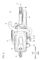
- FIG. 1 is a side view of an engine-driven cutter 10
- FIG. 2 is a plan view of the engine-driven cutter 10.
- FIG. 3 is a cross sectional view of line III-III in FIG. 1 .
- the engine-driven cutter 10 comprises a disk blade 12, and a main body 14 that drives the disk blade 12.
- the disk blade 12 can cut lithic materials and metal materials, and the engine-driven cutter 10 is used e.g. for cutting concrete and steel materials at a building site.
- the disk blade 12 is positioned on one side of the horizontal direction relative to the main body 14.
- a state where the engine-driven cutter 10 is mounted on the horizontal plane H is used as the reference, and one side of the horizontal direction where the disk blade 12 is positioned relative to the main body 14 is referred to as a front side, and the opposite direction thereof is referred to as a rear side.
- the vertical upward direction is simply referred to as an upper side and the vertical downward direction is simply referred to as a lower side.
- one side of the horizontal direction that is perpendicular to the front-back direction is referred to as a left side and the other side of the horizontal direction perpendicular to the front-back direction is referred to as a right side.
- the disk blade 12 is positioned in front of the main body 14, and its rotating axis extends in the left-right direction and perpendicular to the horizontal plane H at the upper side of the horizontal plane H.
- the main body 14 is provided with a front handle 16 and a rear grip 28.
- the front handle 16 is formed with a pipe material, and, in addition to being a handle to be grasped by the user, it also functions as a frame for ensuring the strength of the main body 14.
- the front handle 16 extends from the upper side to the left side of the main body 14 at the front part of the main body 14.
- the rear grip 28 is provided in the lower rear part of the main body 14.
- the rear grip 28 extends in a loop shape from the main body 14.
- the rear grip 28 is provided with an operation switch such as a throttle lever 30.
- the lower part of the rear grip 28 is provided with a rear foot part 38.
- the engine-driven cutter 10 of this embodiment is a handheld engine-driven cutter that is held by the user.
- the user is positioned on the left side of the main body 14.
- the left side of the engine-driven cutter 10 is also referred to as the user side.
- the main body 14 comprises an engine 18 that drives the disk blade 12.
- the engine 18 is a four-stroke reciprocating engine. With the four-stroke engine, since an intake port and an exhaust port are respectively opened and closed with a valve operating mechanism, there is an advantage in that the emission of unburned gas is low and it is energy-efficient (low fuel consumption) in comparison to a two-stroke engine in which such ports are opened and closed respectively with a piston. Since the engine-driven cutter 10 adopts the four-stroke engine 18, its environmental performance is considerably improved.
- the engine 18 is a separate lubrication system four-stroke engine, unlike a mixed lubrication-type two-stroke engine.
- the engine oil needs to be supplied separately from the fuel. Moreover, the engine oil needs to be replenished and replaced at an adequate frequency.
- the engine 18 is provided with an oil supplying opening 18a to which the engine oil is fed, and an oil exhausting opening 18b for exhausting the engine oil.
- the engine 18 is not limited to the separate lubrication system four-stroke engine, and it may also be a mixed lubrication system four-stroke engine.
- the separate lubrication system four-stroke engine has an advantage in that it yields superior environmental performance in comparison to the mixed lubrication system four-stroke engine, since a large amount of engine oil is subject to cyclic use in the engine, and the amount of engine oil that is consumed together with the fuel is extremely small. Moreover, running costs to be borne by a user can also be reduced since the consumption of the engine oil is reduced.
- the mixed lubrication system four-stroke engine is employed in a case where the engine-driven cutter 10 is not used for a long period of time, the fuel in the carburetor will evaporate causing only the engine oil to remain therein, and the carburetor may become clogged.
- the separate lubrication system four-stroke engine the effect of being able to avoid this kind of problem can also be expected.
- the main body 14 comprises a cutter arm 56 mounted on the disk blade 12.
- the cutter arm 56 is provided on the right side of the main body 14, and extends toward the front side of the main body 14.
- the cutter arm 56 comprises a first plate 56b fixed to the engine 18 and a second plate 56c fixed to the first plate 56b, and the second plate 56c is provided with a tool shaft 56e for rotatably supporting the disk blade 12.
- the cutter arm 56 comprises a drive pulley 56a fixed to the driving axis (crank shaft) 18c of the engine 18, a driven pulley 56f fixed to the tool shaft 56e, and a transmission belt 56d placed across the drive pulley 56a and the driven pulley 56f. Consequently, torque output by the engine 18 is transmitted to the tool shaft 56e, and the disk blade 12 is rotatably driven by the engine 18. Accordingly, the cutter arm 56 is also a transmission mechanism for transmitting the torque output by the engine 18 to the disk blade 12.
- the right side of the main body 14 to which the cutter arm 56 as the transmitting mechanism is provided is generally referred to as the driving side.
- the position for mutually fixing the first plate 56b and the second plate 56c is adjustable, and the tension of the transmission belt 56d can be adjusted.
- the driving axis 18c of the engine 18 and the tool shaft 56e are mutually parallel, and they both extend in the left-right direction.
- the cutter arm 56 is provided with a disk blade cover 58 for covering the disk blade 12.
- the main body 14 comprises a recoil starter 44 for the user to start the engine 18.
- the recoil starter 44 is provided on the right side of the main body 14, and provided above the cutter arm 56. As shown in FIG. 3 , the driving axis 18c of the engine 18 extends by passing through the drive pulley 56a, and the recoil starter 44 is connected to the distal end of the driving axis 18c.
- the recoil starter 44 is provided with a starter lever 42 to be operated by the user. When the user pulls the starter lever 42, the driving axis 18c of the engine 18 rotates and the engine 18 is started.
- the main body 14 comprises a guard 50.
- the guard 50 is provided on the lower front side of the main body 14.
- the lower front side of the main body 14 is a position where chips of a workpiece scatter from the disk blade 12, and the guard 50 repels the scattered chips of the workpiece toward the lower side of the main body 14. Consequently, the chips of the workpiece that collide with the main body 14 are prevented from being repelled toward the user.
- the guard 50 is provided with a pair of rollers 52 and a front leg portion 54. The pair of rollers 52 are positioned more toward the front side than the front leg portion 54.
- the pair of rollers 52 contact the surface of the workpiece and become a fulcrum for angling the engine-driven cutter 10 towards the workpiece. Note that the structure of the guard 50 is explained in detail later.
- the main body 14 comprises a casing 20.
- the casing 20 is formed from a resin material.
- the casing 20 comprises a casing main body 26, a filter cover 24, and a top cover 22.
- the top cover 22 is fixed to the filter cover 24, and the filter cover 24 is fixed to the casing main body 26.
- a part of the casing main body 26 is a fuel tank for storing the fuel of the engine 18, and is provided with a fuel supplying opening 40 for supplying the fuel.
- the casing main body 26 is integrally formed with the rear grip 28 described above, and the internal space of the rear grip 28 also constitutes a part of the fuel tank.
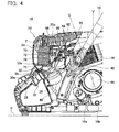
- FIG. 4 shows the right side of the main body 14. Note that, in FIG. 4 , a part thereof is a cross section, and the structure inside the casing 20 is shown.
- the oil supplying opening 18a and the oil exhausting opening 18b are both provided on the right side of the main body 14. As described above, if the oil supplying opening 18a and the oil exhausting opening 18b are both provided on the same side of the main body 14, the user can replace the engine oil without having to change the direction of the engine-driven cutter 10 or change one's position relative to the engine-driven cutter 10.
- the oil supplying opening 18a and the oil exhausting opening 18b can be visually confirmed simultaneously, it is possible to prevent a mistake such as continuing to supply the engine oil from the oil supplying opening 18a while forgetting to close the oil exhausting opening 18b.
- the oil supplying opening 18a and the oil exhausting opening 18b are disposed on the right side (driving side) of the main body 14, the oil supplying opening 18a and the oil exhausting opening 18b will not get in the way of the user positioned on the opposite left side (user side).
- the recoil starter 44, the starter lever 42, and the fuel supplying opening 40 are also provided on the right side (driving side) of the main body 14. Accordingly, existence of the recoil starter 44, the starter lever 42, and the fuel supplying opening 40 will not get in the way of the user positioned on the opposite left side (user side). Accordingly, with the engine-driven cutter 10 of this embodiment, the oil supplying opening 18a, the oil exhausting opening 18b, the recoil starter 44, the starter lever 42, and the fuel supplying opening 40 are all provided on the right side (driving side) of the main body 14 where the cutter arm 56 is positioned. Accordingly, as shown in FIG.
- a large concavo-convex does not exist on the left side (user side) of the main body 14 in comparison to the right side (driving side) of the main body 14. Consequently, the user can comfortably perform operations without having to mind the concavo-convex of the main body 14.
- the internal structure of the casing 20 is now explained. As shown in FIG. 4 , a flow path shown with arrow F in FIG. 4 is formed in the casing 20, and the structure is such that the air introduced from the intake window 22a of the top cover 22 passes through the casing 20 and is supplied to the engine 18 via an intake connecting tube 62.
- the casing 20 is internally provided with a pre-filter 68, a main filter 70, and a carburetor 74 along the foregoing flow path F.
- the pre-filter 68 is positioned between the top cover 22 and the filter cover 24, and the main filter 70 is positioned between the filter cover 24 and the casing main body 26.
- the pre-filter 68 is positioned at the upper side of the main filter 70 in a state where the engine-driven cutter 10 is mounted on the horizontal plane H.
- the air introduced from the intake window 22a passes through the pre-filter 68 and the main filter 70 in that order, and the dust contained therein is removed (or filtered).
- the air passes through from the lower side to the upper side of the pre-filter 68, it flows along the inner surface of the top cover 22 and the filter cover 24, and passes through the main filter 70 after changing its direction of flow approximately 270 degrees.
- the air that passed through the main filter 70 subsequently passes through the carburetor 74.
- the carburetor 74 mixes the air that passed through the main filter 70 with the fuel.
- the carburetor 74 is a general-purpose carburetor, and includes a throttle valve, a check valve, an air vent and the like.
- the air that was mixed with the fuel in the carburetor 74 passes through the intake connecting tube 62 is supplied to the engine 18.
- the intake connecting tube 62 is positioned outside of the casing 20.
- FIG. 4 shows the breathing tube 64 at the upper side of the intake connecting tube 62.
- the breathing tube 64 extends from the engine 18, and is connected to an oil separator 82 described later.
- the breathing tube 64 is a pipeline for eliminating blow-by gas discharged inside the locker cover within the engine 18, and is connected to a circulatory path of the engine oil including a crank casing within the engine 18.
- the engine-driven cutter 10 of this embodiment adopts the four-stroke engine 18.
- the intake port is provided in the cylinder head, and the carburetor 74 connected to the intake port is positioned relatively on the upper side.
- the main filter 70 is positioned at the upper side of the carburetor 74, the main filter 70 will protrude considerably toward the upper side relative to the engine 18, and the height of the engine-driven cutter 10 is increased.
- the main filter 70 and the carburetor 74 are arranged to align on a straight line along the direction of flow of the air passing through the main filter 70 and the carburetor 74.
- the carburetor 74 is positioned at the rear side of the engine 18 and the main filter 70 is positioned at the rear side of the carburetor 74. According to this kind of arrangement and structure, even if the four-stroke engine 18 is adopted, the height of the engine-driven cutter 10 can be kept relatively small.
- a relatively large main filter 70 is adopted, and a part of the main filter 70 is protruding toward the upper side of the rear grip 28. Consequently, the rear surface of the casing 20 (portion of the filter cover 24) is also protruding in a convex shape at the upper side of the rear grip 28. Accordingly, if a part or the entirety of the main filter 70 is disposed to protrude up reaching the upper side of the rear grip 28, a large main filter 70 can be mounted. As a result of mounting the large main filter 70, the main filter 70 does not clog easily, and the user needs to clean the main filter 70 less frequently.
- the two-stroke engine is adopted.
- the intake port is provided in the cylinder block and the carburetor connected to the intake port is positioned relatively low. Consequently, with the conventional engine-driven cutter, the main filter 70 is disposed at the upper side of the carburetor 74, and the downsizing of the engine-driven cutter is thereby being sought (for example, refer to Japanese Patent Application Publication No. 2007-528792 ).
- the design is such that a central axis C of the cylinder of the engine 18 is angled towards the carburetor 74 relative to a vertical direction V. If the engine 18 is disposed as described above, the carburetor 74 and the main filter 70 connected to the engine 18 can be positioned even lower. Consequently, the height of the engine-driven cutter 10 can be reduced.
- the four-stroke engine includes a valve operating mechanism above the cylinder head and the oil pan below the crank casing, its height is relatively great in comparison to the two-stroke engine, and there is a possibility that this may cause the enlargement of the engine-driven cutter 10. With respect to this point also, if the engine 18 is angled and positioned as described above, the engine-driven cutter 10 can be designed to be compact.
- a filter bracket 72 is provided between the main filter 70 and the carburetor 74.
- the filter bracket 72 guides the air that passed through the main filter 70 to the carburetor 74.
- the filter bracket 72 is fixed to the casing main body 26, and retains the main filter 70 at a fixed position.
- the filter bracket 72 is fixed to the casing main body 26 together with the filter cover 24 with a mutual bolt 84.
- this structure it is possible to simplify the structure and reduce the number of components in comparison to the structure where the filter bracket 72 and the filter cover 24 are separately fixed, and the further downsizing of the engine-driven cutter 10 can be sought.
- the assembly process of the engine-driven cutter 10 can be simplified. Note that, although not shown in FIG. 4 and FIG. 5 , as described later, the carburetor 74, the carburetor mount 66, the intake connecting tube 62 and the like are assembled to the filter bracket 72 in advance. Moreover, a main filter 70 is disposed between the filter cover 24 and the filter bracket 72 upon the assembly thereof.
- the casing 20 includes a carburetor mount 66 to which the carburetor 74 is fixed.
- the carburetor mount 66 is mounted on a notch portion 26a of the casing main body 26 shown in FIG. 4 and FIG. 5 , and configures a part of the outer wall of the casing 20.
- the carburetor mount 66 is mounted on the casing main body 26 via a seal member 76.
- the seal member 76 is an elastic member formed with a material with elasticity. In this embodiment, as one example, the seal member 76 is formed with a polymer material (more specifically a rubber material).
- the carburetor mount 66 can be displaced relative to the casing main body 26 based on the deformation of the seal member 76.
- FIG. 7 shows a group of components that is assembled to the carburetor mount 66.
- the filter bracket 72 and the intake connecting tube 62 are assembled to the carburetor mount 66 in addition to the carburetor 74.
- the filter bracket 72 and the carburetor 74 and the carburetor mount 66 and the intake connecting tube 62 are mutually assembled with a mutual bolt 80.
- a gasket 78 is disposed between the filter bracket 72 and the carburetor 74 upon assembling the foregoing group of components, and a seal member 76 is disposed at the peripheral edge of the carburetor mount 66.
- the carburetor mount 66 includes two supporting beam portions 66b protruding toward the carburetor 74.
- the supporting beam portions 66b support the carburetor 74 from the bottom and retain the carburetor 74 at the assembly position upon assembling the filter bracket 72 to the carburetor mount 66 with the carburetor 74 interposed therebetween.
- the supporting beam portion 66b retaining the carburetor 74, the operator to perform such assembly can easily perform the assembly process without having to support the carburetor 74 with one's hand.
- the carburetor mount 66 is formed with a recess portion 66c.
- the recess portion 66c is formed on a surface that is positioned on the side of the carburetor 74.
- the recess portion 66c faces the arm 74c that opens and closes the throttle valve of the carburetor 74, and prevents the arm 74c from contacting the carburetor mount 66.
- the space between the carburetor mount 66 and the filter bracket 72 can be designed to be narrow, and the downsizing of the engine-driven cutter 10 can thereby be sought.
- the filter bracket 72 is fixed to the carburetor mount 66 with the carburetor 74 interposed therebetween as shown in FIG. 7 , and thereafter fixed to the casing main body 26 as shown in FIG. 5 and FIG. 6 .
- the carburetor mount 66 is mounted on the notch portion 26a of the casing main body 26 via the seal member 76. Accordingly, even if there is a dimension error in the filter bracket 72, the casing main body 26, and the carburetor mount 66, the filter bracket 72 can be properly fixed to the casing main body 26 by the carburetor mount 66 subordinately displacing in accordance with the casing main body 26 to compensate for the dimension error.
- FIG. 9 and FIG. 10 show a connection relationship concerning a flow path constituted of the filter bracket 72, the carburetor 74, the carburetor mount 66, and the seal member 76.
- FIG. 9 and FIG. 10 when the filter bracket 72 is assembled to the carburetor mount 66 with the carburetor 74 intervening therebetween, an opening 72a of the filter bracket 72 is connected to an opening 66a of the carburetor mount 66 via a main path 74a of the carburetor 74.
- an oil separator 82 is integrally formed to the filter bracket 72. Moreover, the oil separator 82 is protruding from the filter bracket 72 towards the carburetor 74. In a case where the structure is such that the oil separator 82 protrudes towards the main filter 70, it is not possible to prevent the oil separator 82 from interfering with the main filter 70, and it is necessary to design the filter bracket 72 to be sufficiently larger than the oil separator 82. Meanwhile, if the structure is such that the oil separator 82 protrudes toward the carburetor 74, the oil separator 82 can be easily provided at a position that does not interfere with the carburetor 74 without having to enlarge the filter bracket 72.
- the seal member 76 is formed with two through holes 76a.
- the position of the two through holes 76a corresponds to the position of two nipple portions 82a of the oil separator 82.
- the nipple portion 82a of the oil separator 82 is a connecting opening that protrudes in a tubular shape with a rib
- the through hole 76a of the seal member 76 is a receiving opening for receiving the nipple portion 82a.
- a periphery 76b, 76c of the through hole 76a is protruding in a tubular shape by a rib at the front and back of the seal member 76.
- the breathing tube 64 is connected to the through hole 76a of the seal member 76 via a joint 65.
- the breathing tube 64 may also be connected directly to the through hole 76a of the seal member 76 without using the joint 65.
- the carburetor 74 is provided with a hose nipple 74b connected to an air vent.
- the distal end of the hose nipple 74b extends toward the filter bracket 72.
- the filter bracket 72 is provided with an air vent connecting opening 72b at a position corresponding to the hose nipple 74b.
- the throttle lever 30 is supported with the shaft 34, and is swingable around the shaft 34.
- the throttle lever 30 is connected to the throttle valve of the carburetor 74 via a link 30a.
- the switch lever 32 is also mounted on the same shaft 34 in addition to the throttle lever 30.
- the switch lever 32 is also swingable around the shaft 34.
- the switch lever 32 is connected to the choke valve of the carburetor 74 via the link 32a.
- FIG. 12 shows a state where the throttle lever 30 and the switch lever 32 are assembled to the casing main body 26, and FIG. 13 shows a state where they are disassembled.
- the casing main body 26 is formed with a shaft receiving groove 26b extending in the axial direction of the shaft 34.
- the shaft receiving groove 26b retains the shaft 34 from its radial direction. Since the upper side of the shaft receiving groove 26b is open, the shaft 34 can be easily fitted into the shaft receiving groove 26b. In particular, the shaft 34 can be fitted into the shaft receiving groove 26b in a state where the throttle lever 30, a spring member 30b, and the switch lever 32 are mounted on the shaft 34 in advance.
- the respective levers 30, 32 apply downward force to the shaft 34.
- the opening direction of the shaft receiving groove 26b is facing the upper side. Accordingly, since the opening direction of the shaft receiving groove 26b and the direction that the shaft 34 receives the force from the respective levers 30, 32 are mutually different, the shaft 34 is securely retained by the shaft receiving groove 26b, and the behavior of the respective levers 30, 32 is thereby stabilized.
- the shaft receiving groove 26b is divided into two sections, and the structure is such that a space surrounding the shaft 34 is formed between the two shaft receiving grooves 26b. Accordingly, if the structure is such that one or more shaft receiving grooves 26b are provided only in the lengthwise direction of a part of the shaft 34, and space is formed around the shaft 34 in a remaining lengthwise range, the shaft 34 that is mounted on the shaft receiving grooves 26b can be easily removed.
- the filter bracket 72 is formed with a shaft holding portion 72c at two locations.
- the shaft holding portions 72c come in contact with the shaft 34 retained by the shaft receiving grooves 26b from the opening direction of the shaft receiving grooves 26b (upper side in this embodiment). According to this structure, it is possible to prevent the shaft 34 retained by the shaft receiving grooves 26b from moving or coming loose from the shaft receiving grooves 26b without having to provide a separate member for holding the shaft 34.
- the filter bracket 72 also functions as a support pillar (or beam) within the casing 20, and is able to significantly improve the rigidity of the casing 20.
- the casing main body 26 is provided with a pair of shaft position determining portions 26c respectively facing the respective ends of the shaft 34. According to this structure, it is possible to prevent the shaft 34 retained by the shaft receiving grooves 26b from moving in the axial direction and coming loose from the shaft receiving grooves 26b without having to provide a retaining member such as a circlip to the shaft 34.
- FIG. 14 is a diagram showing the right side of the guard 50
- FIG. 15 is a diagram showing the front side of the guard 50
- FIG. 16 is a diagram showing the lower side of the guard 50
- FIG. 17 is a cross section of line XVII-XVII in FIG. 14
- FIG. 18 is a cross section of line XVIII-XVIII in FIG. 16
- FIG. 19 shows a state where a workpiece W is being cut with the engine-driven cutter 10.
- a straight line S in the drawings shows a rotating plane of the disk blade 12.
- the rotating plane S is a virtual plane where the rotating disk blade 12 is positioned, and is a plane that is perpendicular to the rotating axis of the disk blade 12 and which includes the disk blade 12. However, since the disk blade 12 has a limited thickness, the rotating plane S is defined to match the position of one end surface of the disk blade 12. Moreover, an arrow D in FIG. 19 shows the path that the chips of the workpiece W will scatter.
- the guard 50 comprises a guard surface 90, a pair of rollers 52, and a front leg portion 54.
- the front leg portion 54 is molded such that its corner portion 54a is formed as a curved surface so that the user can easily angle the engine-driven cutter 10.
- the pair of rollers 52 is disposed coaxially with the rotating plane S of the disk blade 12 interposed therebetween, and the rotating axis thereof is parallel to the rotating axis of the disk blade 12.
- the guard surface 90 is provided between the pair of rollers 52.
- the guard surface 90 is a groove-shaped curved surface formed on the guard 50, and extends along the rotating plane S of the disk blade 12.
- the guard surface 90 has a tilted surface which basically faces obliquely downward toward the front side. Specifically, the guard surface 90 is tilted to be apart from the surface of the workpiece as the front side position is closer to the disk blade 12. The guard surface 90 repels the chips of the workpiece that scattered from the disk blade 12 toward the lower side of the main body 14. Consequently, it is possible to prevent the chips of the workpiece that scattered from the disk blade 12 in the main body 14 from being repelled toward the user.
- the guard 50 is formed with a plurality of positioning protrusions 50a, and is configured so that it can be easily assembled to the main body 14.
- the guard surface 90 can be formed as a surface that is free from concavo-convex or a surface with little concavo-convex so that the chips of the workpiece are smoothly guided to the lower side of the main body 14.
- grooves and protrusions may be intentionally provided for guiding the chips of the workpiece to a specific direction.
- the guard surface 90 has different shapes in a left side (user side) range 90a and a right side (driving side) range 90b with the rotating plane S as the boundary. Specifically, the guard surface 90 has an asymmetric shape with the rotating plane S as the boundary. Consequently, the guard surface 90 repels the chips scattered from the disk blade 12 asymmetrically to the rotating plane S of the disk blade 12.
- the normal vector N is tilted toward the rotating plane S so as to face the rotating plane S in the entire left side (user side) range 90a.
- the depth becomes narrow as it becomes separated from the rotating plane S.
- the chips that scattered from the disk blade 12 are repelled toward the rotating plane S.
- the chips that scattered from the disk blade 12 to the left side (user side) can be repelled toward the right side (driving side).
- the shape of the guard surface 90 described above is an example, and the shape of the guard surface 90 is not limited thereto. The shape will suffice so as long as a majority of the chips that scattered from the disk blade 12 can be repelled to the right side (driving side) of the main body 14, and, for example, the angle, depth, and area of the guard surface 90 may be changed between the left side (user side) range 90a and the right side (driving side) range 90b.
- the user can move the engine-driven cutter 10 along the surface of the workpiece W in a state of causing the pair of rollers 52 to come in contact with the surface of the workpiece W and angling the engine-driven cutter 10 towards the surface of the workpiece W.
- the pair of rollers 52 are used as the fulcrum, and, even when the engine-driven cutter 10 is fully angled towards the surface of the workpiece W (state of FIG.
- the guard surface 90 is tilted to become separated from the surface of the workpiece W as it approaches the disk blade 12 (front side). Specifically, a height T from the surface of the workpiece W to the guard surface 90 becomes higher as it approaches the disk blade 12 (front side). According to this structure, regardless of the angle when the engine-driven cutter 10 is angled towards the surface of the workpiece W, it is possible to go over the obstacle existing on the surface of the workpiece W based on the tilt of the guard surface 90.
Landscapes
- Engineering & Computer Science (AREA)
- Mechanical Engineering (AREA)
- General Engineering & Computer Science (AREA)
- Chemical & Material Sciences (AREA)
- Combustion & Propulsion (AREA)
- Sawing (AREA)
- Processing Of Stones Or Stones Resemblance Materials (AREA)
- Harvester Elements (AREA)
- Lubrication Of Internal Combustion Engines (AREA)
- Lubrication Details And Ventilation Of Internal Combustion Engines (AREA)
Abstract
Description
- The present invention relates to a handheld engine-driven cutter that drives a disk blade by an engine.
- Japanese Patent Application Publication No.
2007-528792 - Nevertheless, the two-stroke engine has a problem in that its emission of unburned gas is high, and its adverse effect on the natural environment is relatively great. Demands for environmental performance are also increasing with handheld engine-driven cutters, and it is difficult for the conventional products adopting the two-stroke engine to satisfy the high level of environmental performance that is being demanded.
- In light of the foregoing circumstances, a use of a four-stroke engine in substitute for the two-stroke engine in the handheld engine-driven cutter may be considered. With the four-stroke engine, since its intake port and exhaust port are respectively opened and closed with a valve operating mechanism, there is an advantage in that the emission of unburned gas is low and it is energy-efficient in comparison to the two-stroke engine in which the ports are opened and closed respectively with a piston. In particular, with a separate lubrication system four-stroke engine, since a large amount of engine oil is subject to cyclic use within the engine and the amount of engine oil that is consumed together with fuel is extremely small, the environmental performance can be improved even further.
- However, with the separate lubrication system four-stroke engine, unlike a mixed lubrication system two-stroke engine or a four-stroke engine that uses fuel with engine oil mixed therein, the engine oil needs to be supplied separately from the fuel. Moreover, the engine oil needs to be replenished and replaced in an adequate frequency. Thus, if the separate lubrication system four-stroke engine is adopted in the engine-driven cutter, it is anticipated that a user who has been using the conventional product will have trouble or even be unsuccessful in replacing the engine oil due to inexperience.
- Accordingly, an object of this invention is to provide teachings for facilitating the replacement of the engine oil in the engine-driven cutter mounted with the four-stroke engine.
- In one aspect of the present teachings, a handheld engine-driven cutter comprises a disk blade, and a main body that drives the disk blade. The main body comprises a four-stroke engine, an oil supplying opening from which engine oil is supplied, and an oil exhausting opening from which the engine oil is exhausted. This engine-driven cutter has the oil supplying opening and the oil exhausting opening disposed on one side of the main body.
- If the oil supplying opening and the oil exhausting opening are both disposed on the same side of the main body, the user can replace the engine oil without having to change the direction of the engine-driven cutter or change one's position relative to the engine-driven cutter. Moreover, since the oil supplying opening and the oil exhausting opening can be visually confirmed simultaneously, it is possible to prevent a mistake such as continuing to supply the engine oil from the oil supplying opening while forgetting to close the oil exhausting opening. If the oil supplying opening and the oil exhausting opening are disposed on one side of the main body, the user can comfortably perform operations without having to mind the oil supplying opening or the oil exhausting opening by using the engine-driven cutter while being in a position on the other side of the main body.
- According to the aforementioned structure, it is possible to realize an engine-driven cutter mounted with a four-stroke engine in which the replacement of the engine oil is facilitated (easy to understand). Moreover, it is possible to realize an engine-driven cutter that can be used by the user comfortably without having to mind the existence of the oil supplying opening and the oil exhausting opening.
-
-
FIG. 1 shows a view of an engine-driven cutter from a right side (driving side). -
FIG. 2 shows a plan view of the engine-driven cutter from above. -
FIG. 3 is a cross sectional view of line III-III inFIG. 1 . -
FIG. 4 is a partial cross sectional view of a main body of the engine-driven cutter. -
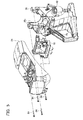
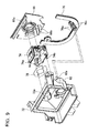
FIG. 5 shows an assembly structure of a casing main body and a filter bracket and a filter cover. -
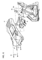
FIG. 6 is another view of the assembly structure of the casing main body and the filter bracket and the filter cover from a different direction from that ofFIG. 5 . -
FIG. 7 shows an assembly structure of a filter bracket and a carburetor and a carburetor mount. -
FIG. 8 shows a positional relationship of a carburetor arm and a recess portion of the carburetor mount. -
FIG. 9 shows a connection structure of the filter bracket and the carburetor and the carburetor mount. -
FIG. 10 shows the connection structure of the filter bracket and the carburetor and the carburetor mount from a different direction from that ofFIG. 9 . -
FIG. 11 shows a state where an oil separator and a breathing tube are mutually connected via a through hole of a seal member. -
FIG. 12 shows an assembly structure of a throttle lever and a switch lever. -
FIG. 13 is an exploded view of an assembly structure of the throttle lever and the switch lever. -
FIG. 14 shows a guard from the right side. -
FIG. 15 shows the guard from a front side. -
FIG. 16 shows the guard from a bottom side. -
FIG. 17 is a cross sectional view of line XVII-XVII inFIG. 14 . -
FIG. 18 is a cross sectional view of line XVIII-XVIII inFIG. 16 . -
FIG. 19 shows a state where the engine-driven cutter is fully angled towards a surface of a workpiece. - In one embodiment of the present teachings, the main body may further comprise a fuel supplying opening from which fuel is supplied. In the foregoing case, preferably, the fuel supplying opening is also disposed on the one side of the main body as with the oil supplying opening and the oil exhausting opening. According to this structure, the user visually confirms the oil supplying opening and the fuel supplying opening simultaneously. Consequently, it is possible to prevent the user from erroneously supplying the fuel to the oil supplying opening or erroneously supplying the engine oil to the fuel supplying opening. In addition, the user can comfortably perform operations without having to mind the existence of the oil supplying opening, the oil exhausting opening, and the fuel supplying opening by using the engine-driven cutter while being in a position on the other side of the main body.
- In one embodiment of the present teachings, the main body may further comprise a starter member that is operated by the user to start the four-stroke engine. In the foregoing case, preferably, the starter member is also disposed on the one side of the main body as with the oil supplying opening and the oil exhausting opening. According to the foregoing structure, the user can comfortably perform operations without having to mind the existence of the oil supplying opening, the oil exhausting opening, and the starter member by using the engine-driven cutter while being in the position on the other side of the main body.
- In one embodiment of the present teachings, the main body may further comprise a transmission mechanism that supports the disk blade and transmits torque of the four-stroke engine to the disk blade. In the foregoing case, preferably, the transmitting mechanism is also disposed on the one side of the main body as with the oil supplying opening and the oil exhausting opening. According to the foregoing structure, the user can comfortably perform operations without having to mind the existence of the oil supplying opening, the oil exhausting opening, and the transmitting mechanism by using the engine-driven cutter while being in the position on the other side of the main body.
- Representative, non-limiting examples of the present invention will now be described in further detail with reference to the attached drawings. This detailed description is merely intended to teach a person of skill in the art further details for practicing preferred aspects of the present teachings and is not intended to limit the scope of the invention. Furthermore, each of the additional features and teachings disclosed below may be utilized separately or in conjunction with other features and teachings to provide improved engine-driven cutters.
- Moreover, combinations of features and steps disclosed in the following detail description may not be necessary to practice the invention in the broadest sense, and are instead taught merely to particularly describe representative examples of the invention. Furthermore, various features of the above-described and below-described representative examples, as well as the various independent and dependent claims, may be combined in ways that are not specifically and explicitly enumerated in order to provide additional useful embodiments of the present teachings.
- All features disclosed in the description and/or the claims are intended to be disclosed separately and independently from each other for the purpose of original written disclosure, as well as for the purpose of restricting the claimed subject matter, independent of the compositions of the features in the embodiments and/or the claims. In addition, all value ranges or indications of groups of entities are intended to disclose every possible intermediate value or intermediate entity for the purpose of original written disclosure, as well as for the purpose of restricting the claimed subject matter.
- Examples of an engine-driven cutter are explained below with reference to the appended drawings.
FIG. 1 is a side view of an engine-drivencutter 10, andFIG. 2 is a plan view of the engine-drivencutter 10. Moreover,FIG. 3 is a cross sectional view of line III-III inFIG. 1 . The engine-drivencutter 10 comprises adisk blade 12, and amain body 14 that drives thedisk blade 12. Thedisk blade 12 can cut lithic materials and metal materials, and the engine-drivencutter 10 is used e.g. for cutting concrete and steel materials at a building site. - As shown in
FIG. 1 andFIG. 2 , when the engine-drivencutter 10 is mounted on a horizontal plane H, thedisk blade 12 is positioned on one side of the horizontal direction relative to themain body 14. In the ensuing explanation, a state where the engine-drivencutter 10 is mounted on the horizontal plane H is used as the reference, and one side of the horizontal direction where thedisk blade 12 is positioned relative to themain body 14 is referred to as a front side, and the opposite direction thereof is referred to as a rear side. Moreover, the vertical upward direction is simply referred to as an upper side and the vertical downward direction is simply referred to as a lower side. In addition, as shown inFIG. 2 , one side of the horizontal direction that is perpendicular to the front-back direction is referred to as a left side and the other side of the horizontal direction perpendicular to the front-back direction is referred to as a right side. For example, thedisk blade 12 is positioned in front of themain body 14, and its rotating axis extends in the left-right direction and perpendicular to the horizontal plane H at the upper side of the horizontal plane H. - The
main body 14 is provided with afront handle 16 and arear grip 28. Thefront handle 16 is formed with a pipe material, and, in addition to being a handle to be grasped by the user, it also functions as a frame for ensuring the strength of themain body 14. Thefront handle 16 extends from the upper side to the left side of themain body 14 at the front part of themain body 14. Therear grip 28 is provided in the lower rear part of themain body 14. Therear grip 28 extends in a loop shape from themain body 14. Therear grip 28 is provided with an operation switch such as athrottle lever 30. Moreover, the lower part of therear grip 28 is provided with arear foot part 38. - Normally, the user grasps the
front handle 16 with one's left hand, and grasps therear grip 28 with one's right hand to hold the engine-drivencutter 10. The user moves the engine-drivencutter 10 relative to the workpiece and cuts the workpiece with thedisk blade 12. As described above, the engine-drivencutter 10 of this embodiment is a handheld engine-driven cutter that is held by the user. Here, when the user holds the engine-drivencutter 10 as described above, the user is positioned on the left side of themain body 14. Normally, since the user is positioned on the left side of the engine-drivencutter 10, the left side of the engine-drivencutter 10 is also referred to as the user side. - The
main body 14 comprises anengine 18 that drives thedisk blade 12. Theengine 18 is a four-stroke reciprocating engine. With the four-stroke engine, since an intake port and an exhaust port are respectively opened and closed with a valve operating mechanism, there is an advantage in that the emission of unburned gas is low and it is energy-efficient (low fuel consumption) in comparison to a two-stroke engine in which such ports are opened and closed respectively with a piston. Since the engine-drivencutter 10 adopts the four-stroke engine 18, its environmental performance is considerably improved. - Since the
engine 18 is a separate lubrication system four-stroke engine, unlike a mixed lubrication-type two-stroke engine. The engine oil needs to be supplied separately from the fuel. Moreover, the engine oil needs to be replenished and replaced at an adequate frequency. Thus, theengine 18 is provided with anoil supplying opening 18a to which the engine oil is fed, and anoil exhausting opening 18b for exhausting the engine oil. - Note that the
engine 18 is not limited to the separate lubrication system four-stroke engine, and it may also be a mixed lubrication system four-stroke engine. However, the separate lubrication system four-stroke engine has an advantage in that it yields superior environmental performance in comparison to the mixed lubrication system four-stroke engine, since a large amount of engine oil is subject to cyclic use in the engine, and the amount of engine oil that is consumed together with the fuel is extremely small. Moreover, running costs to be borne by a user can also be reduced since the consumption of the engine oil is reduced. Furthermore, if the mixed lubrication system four-stroke engine is employed in a case where the engine-drivencutter 10 is not used for a long period of time, the fuel in the carburetor will evaporate causing only the engine oil to remain therein, and the carburetor may become clogged. With respect to this point, by adopting the separate lubrication system four-stroke engine, the effect of being able to avoid this kind of problem can also be expected. - The
main body 14 comprises acutter arm 56 mounted on thedisk blade 12. Thecutter arm 56 is provided on the right side of themain body 14, and extends toward the front side of themain body 14. As shown inFIG. 3 , thecutter arm 56 comprises afirst plate 56b fixed to theengine 18 and asecond plate 56c fixed to thefirst plate 56b, and thesecond plate 56c is provided with a tool shaft 56e for rotatably supporting thedisk blade 12. - Moreover, the
cutter arm 56 comprises adrive pulley 56a fixed to the driving axis (crank shaft) 18c of theengine 18, a drivenpulley 56f fixed to the tool shaft 56e, and atransmission belt 56d placed across thedrive pulley 56a and the drivenpulley 56f. Consequently, torque output by theengine 18 is transmitted to the tool shaft 56e, and thedisk blade 12 is rotatably driven by theengine 18. Accordingly, thecutter arm 56 is also a transmission mechanism for transmitting the torque output by theengine 18 to thedisk blade 12. The right side of themain body 14 to which thecutter arm 56 as the transmitting mechanism is provided is generally referred to as the driving side. Here, the position for mutually fixing thefirst plate 56b and thesecond plate 56c is adjustable, and the tension of thetransmission belt 56d can be adjusted. Note that the drivingaxis 18c of theengine 18 and the tool shaft 56e are mutually parallel, and they both extend in the left-right direction. Moreover, thecutter arm 56 is provided with adisk blade cover 58 for covering thedisk blade 12. - The
main body 14 comprises arecoil starter 44 for the user to start theengine 18. Therecoil starter 44 is provided on the right side of themain body 14, and provided above thecutter arm 56. As shown inFIG. 3 , the drivingaxis 18c of theengine 18 extends by passing through thedrive pulley 56a, and therecoil starter 44 is connected to the distal end of the drivingaxis 18c. Therecoil starter 44 is provided with astarter lever 42 to be operated by the user. When the user pulls thestarter lever 42, the drivingaxis 18c of theengine 18 rotates and theengine 18 is started. - The
main body 14 comprises aguard 50. Theguard 50 is provided on the lower front side of themain body 14. The lower front side of themain body 14 is a position where chips of a workpiece scatter from thedisk blade 12, and theguard 50 repels the scattered chips of the workpiece toward the lower side of themain body 14. Consequently, the chips of the workpiece that collide with themain body 14 are prevented from being repelled toward the user. Moreover, theguard 50 is provided with a pair ofrollers 52 and afront leg portion 54. The pair ofrollers 52 are positioned more toward the front side than thefront leg portion 54. When the user raises therear grip 28 to the upper side, the pair ofrollers 52 contact the surface of the workpiece and become a fulcrum for angling the engine-drivencutter 10 towards the workpiece. Note that the structure of theguard 50 is explained in detail later. - The
main body 14 comprises acasing 20. Thecasing 20 is formed from a resin material. Thecasing 20 comprises a casingmain body 26, afilter cover 24, and atop cover 22. Thetop cover 22 is fixed to thefilter cover 24, and thefilter cover 24 is fixed to the casingmain body 26. A part of the casingmain body 26 is a fuel tank for storing the fuel of theengine 18, and is provided with afuel supplying opening 40 for supplying the fuel. Moreover, the casingmain body 26 is integrally formed with therear grip 28 described above, and the internal space of therear grip 28 also constitutes a part of the fuel tank. -
FIG. 4 shows the right side of themain body 14. Note that, inFIG. 4 , a part thereof is a cross section, and the structure inside thecasing 20 is shown. As shown inFIG. 4 , with the engine-drivencutter 10, theoil supplying opening 18a and theoil exhausting opening 18b are both provided on the right side of themain body 14. As described above, if theoil supplying opening 18a and theoil exhausting opening 18b are both provided on the same side of themain body 14, the user can replace the engine oil without having to change the direction of the engine-drivencutter 10 or change one's position relative to the engine-drivencutter 10. Moreover, since theoil supplying opening 18a and theoil exhausting opening 18b can be visually confirmed simultaneously, it is possible to prevent a mistake such as continuing to supply the engine oil from theoil supplying opening 18a while forgetting to close theoil exhausting opening 18b. In addition, since theoil supplying opening 18a and theoil exhausting opening 18b are disposed on the right side (driving side) of themain body 14, theoil supplying opening 18a and theoil exhausting opening 18b will not get in the way of the user positioned on the opposite left side (user side). - In addition to the above, with the engine-driven
cutter 10, therecoil starter 44, thestarter lever 42, and thefuel supplying opening 40 are also provided on the right side (driving side) of themain body 14. Accordingly, existence of therecoil starter 44, thestarter lever 42, and thefuel supplying opening 40 will not get in the way of the user positioned on the opposite left side (user side). Accordingly, with the engine-drivencutter 10 of this embodiment, theoil supplying opening 18a, theoil exhausting opening 18b, therecoil starter 44, thestarter lever 42, and thefuel supplying opening 40 are all provided on the right side (driving side) of themain body 14 where thecutter arm 56 is positioned. Accordingly, as shown inFIG. 2 , a large concavo-convex does not exist on the left side (user side) of themain body 14 in comparison to the right side (driving side) of themain body 14. Consequently, the user can comfortably perform operations without having to mind the concavo-convex of themain body 14. - The internal structure of the
casing 20 is now explained. As shown inFIG. 4 , a flow path shown with arrow F inFIG. 4 is formed in thecasing 20, and the structure is such that the air introduced from theintake window 22a of thetop cover 22 passes through thecasing 20 and is supplied to theengine 18 via anintake connecting tube 62. Thecasing 20 is internally provided with a pre-filter 68, amain filter 70, and acarburetor 74 along the foregoing flow path F. The pre-filter 68 is positioned between thetop cover 22 and thefilter cover 24, and themain filter 70 is positioned between thefilter cover 24 and the casingmain body 26. Thus, the pre-filter 68 is positioned at the upper side of themain filter 70 in a state where the engine-drivencutter 10 is mounted on the horizontal plane H. The air introduced from theintake window 22a passes through the pre-filter 68 and themain filter 70 in that order, and the dust contained therein is removed (or filtered). Here, after the air passes through from the lower side to the upper side of the pre-filter 68, it flows along the inner surface of thetop cover 22 and thefilter cover 24, and passes through themain filter 70 after changing its direction of flow approximately 270 degrees. - The air that passed through the
main filter 70 subsequently passes through thecarburetor 74. Thecarburetor 74 mixes the air that passed through themain filter 70 with the fuel. Thecarburetor 74 is a general-purpose carburetor, and includes a throttle valve, a check valve, an air vent and the like. The air that was mixed with the fuel in the carburetor 74 (so-called air-fuel mixture) passes through theintake connecting tube 62 is supplied to theengine 18. Note that theintake connecting tube 62 is positioned outside of thecasing 20. Moreover,FIG. 4 shows thebreathing tube 64 at the upper side of theintake connecting tube 62. Thebreathing tube 64 extends from theengine 18, and is connected to anoil separator 82 described later. Note that thebreathing tube 64 is a pipeline for eliminating blow-by gas discharged inside the locker cover within theengine 18, and is connected to a circulatory path of the engine oil including a crank casing within theengine 18. - The engine-driven
cutter 10 of this embodiment adopts the four-stroke engine 18. With the four-stroke engine, the intake port is provided in the cylinder head, and thecarburetor 74 connected to the intake port is positioned relatively on the upper side. Thus, if themain filter 70 is positioned at the upper side of thecarburetor 74, themain filter 70 will protrude considerably toward the upper side relative to theengine 18, and the height of the engine-drivencutter 10 is increased. Thus, with the engine-drivencutter 10 of this embodiment, as shown inFIG. 4 , themain filter 70 and thecarburetor 74 are arranged to align on a straight line along the direction of flow of the air passing through themain filter 70 and thecarburetor 74. Specifically, thecarburetor 74 is positioned at the rear side of theengine 18 and themain filter 70 is positioned at the rear side of thecarburetor 74. According to this kind of arrangement and structure, even if the four-stroke engine 18 is adopted, the height of the engine-drivencutter 10 can be kept relatively small. - As shown in
FIG. 4 , with the engine-drivencutter 10 of this embodiment, a relatively largemain filter 70 is adopted, and a part of themain filter 70 is protruding toward the upper side of therear grip 28. Consequently, the rear surface of the casing 20 (portion of the filter cover 24) is also protruding in a convex shape at the upper side of therear grip 28. Accordingly, if a part or the entirety of themain filter 70 is disposed to protrude up reaching the upper side of therear grip 28, a largemain filter 70 can be mounted. As a result of mounting the largemain filter 70, themain filter 70 does not clog easily, and the user needs to clean themain filter 70 less frequently. Note that, even if the rear surface of thecasing 20 protrudes in the convex shape at the upper side of therear grip 28, it will not interfere with the user's hand that will grasp therear grip 28. If such interference becomes a problem, the angle of therear grip 28 may be adjusted. - Note that, with the conventional engine-driven cutter, the two-stroke engine is adopted. With the two-stroke engine, the intake port is provided in the cylinder block and the carburetor connected to the intake port is positioned relatively low. Consequently, with the conventional engine-driven cutter, the
main filter 70 is disposed at the upper side of thecarburetor 74, and the downsizing of the engine-driven cutter is thereby being sought (for example, refer to Japanese Patent Application Publication No.2007-528792 - As shown in
FIG. 4 , with the engine-drivencutter 10, when the engine-drivencutter 10 is mounted on the horizontal plane H, the design is such that a central axis C of the cylinder of theengine 18 is angled towards thecarburetor 74 relative to a vertical direction V. If theengine 18 is disposed as described above, thecarburetor 74 and themain filter 70 connected to theengine 18 can be positioned even lower. Consequently, the height of the engine-drivencutter 10 can be reduced. In addition, since the four-stroke engine includes a valve operating mechanism above the cylinder head and the oil pan below the crank casing, its height is relatively great in comparison to the two-stroke engine, and there is a possibility that this may cause the enlargement of the engine-drivencutter 10. With respect to this point also, if theengine 18 is angled and positioned as described above, the engine-drivencutter 10 can be designed to be compact. - As shown in
FIG. 4 andFIG. 5 , afilter bracket 72 is provided between themain filter 70 and thecarburetor 74. Thefilter bracket 72 guides the air that passed through themain filter 70 to thecarburetor 74. Thefilter bracket 72 is fixed to the casingmain body 26, and retains themain filter 70 at a fixed position. - As shown in
FIG. 5 andFIG. 6 , thefilter bracket 72 is fixed to the casingmain body 26 together with thefilter cover 24 with amutual bolt 84. According to this structure, it is possible to simplify the structure and reduce the number of components in comparison to the structure where thefilter bracket 72 and thefilter cover 24 are separately fixed, and the further downsizing of the engine-drivencutter 10 can be sought. In addition, the assembly process of the engine-drivencutter 10 can be simplified. Note that, although not shown inFIG. 4 andFIG. 5 , as described later, thecarburetor 74, thecarburetor mount 66, theintake connecting tube 62 and the like are assembled to thefilter bracket 72 in advance. Moreover, amain filter 70 is disposed between thefilter cover 24 and thefilter bracket 72 upon the assembly thereof. - As shown in
FIG. 4 , thecasing 20 includes acarburetor mount 66 to which thecarburetor 74 is fixed. Thecarburetor mount 66 is mounted on anotch portion 26a of the casingmain body 26 shown inFIG. 4 andFIG. 5 , and configures a part of the outer wall of thecasing 20. Thecarburetor mount 66 is mounted on the casingmain body 26 via aseal member 76. Theseal member 76 is an elastic member formed with a material with elasticity. In this embodiment, as one example, theseal member 76 is formed with a polymer material (more specifically a rubber material). Thecarburetor mount 66 can be displaced relative to the casingmain body 26 based on the deformation of theseal member 76. -
FIG. 7 shows a group of components that is assembled to thecarburetor mount 66. As shown inFIG. 7 , thefilter bracket 72 and theintake connecting tube 62 are assembled to thecarburetor mount 66 in addition to thecarburetor 74. Here, thefilter bracket 72 and thecarburetor 74 and thecarburetor mount 66 and theintake connecting tube 62 are mutually assembled with amutual bolt 80. Note that agasket 78 is disposed between thefilter bracket 72 and thecarburetor 74 upon assembling the foregoing group of components, and aseal member 76 is disposed at the peripheral edge of thecarburetor mount 66. - As shown in
FIG. 7 , thecarburetor mount 66 includes two supportingbeam portions 66b protruding toward thecarburetor 74. The supportingbeam portions 66b support thecarburetor 74 from the bottom and retain thecarburetor 74 at the assembly position upon assembling thefilter bracket 72 to thecarburetor mount 66 with thecarburetor 74 interposed therebetween. As a result of the supportingbeam portion 66b retaining thecarburetor 74, the operator to perform such assembly can easily perform the assembly process without having to support thecarburetor 74 with one's hand. - As shown in
FIG. 7 , thecarburetor mount 66 is formed with arecess portion 66c. Therecess portion 66c is formed on a surface that is positioned on the side of thecarburetor 74. As shown inFIG. 8 , therecess portion 66c faces thearm 74c that opens and closes the throttle valve of thecarburetor 74, and prevents thearm 74c from contacting thecarburetor mount 66. As described above, as a result of forming therecess portion 66c in a range facing thearm 74c, the space between thecarburetor mount 66 and thefilter bracket 72 can be designed to be narrow, and the downsizing of the engine-drivencutter 10 can thereby be sought. - The
filter bracket 72 is fixed to thecarburetor mount 66 with thecarburetor 74 interposed therebetween as shown inFIG. 7 , and thereafter fixed to the casingmain body 26 as shown inFIG. 5 andFIG. 6 . Here, thecarburetor mount 66 is mounted on thenotch portion 26a of the casingmain body 26 via theseal member 76. Accordingly, even if there is a dimension error in thefilter bracket 72, the casingmain body 26, and thecarburetor mount 66, thefilter bracket 72 can be properly fixed to the casingmain body 26 by thecarburetor mount 66 subordinately displacing in accordance with the casingmain body 26 to compensate for the dimension error. -
FIG. 9 andFIG. 10 show a connection relationship concerning a flow path constituted of thefilter bracket 72, thecarburetor 74, thecarburetor mount 66, and theseal member 76. As shown inFIG. 9 andFIG. 10 , when thefilter bracket 72 is assembled to thecarburetor mount 66 with thecarburetor 74 intervening therebetween, anopening 72a of thefilter bracket 72 is connected to anopening 66a of thecarburetor mount 66 via amain path 74a of thecarburetor 74. - As shown in
FIG. 9 andFIG. 10 , anoil separator 82 is integrally formed to thefilter bracket 72. Moreover, theoil separator 82 is protruding from thefilter bracket 72 towards thecarburetor 74. In a case where the structure is such that theoil separator 82 protrudes towards themain filter 70, it is not possible to prevent theoil separator 82 from interfering with themain filter 70, and it is necessary to design thefilter bracket 72 to be sufficiently larger than theoil separator 82. Meanwhile, if the structure is such that theoil separator 82 protrudes toward thecarburetor 74, theoil separator 82 can be easily provided at a position that does not interfere with thecarburetor 74 without having to enlarge thefilter bracket 72. - As shown in
FIG. 9 andFIG. 10 , theseal member 76 is formed with two throughholes 76a. The position of the two throughholes 76a corresponds to the position of twonipple portions 82a of theoil separator 82. Here, thenipple portion 82a of theoil separator 82 is a connecting opening that protrudes in a tubular shape with a rib, and the throughhole 76a of theseal member 76 is a receiving opening for receiving thenipple portion 82a. Note that aperiphery hole 76a is protruding in a tubular shape by a rib at the front and back of theseal member 76. According to the foregoing configuration, when thefilter bracket 72 is assembled to thecarburetor mount 66 with thecarburetor 74 interposed therebetween, as shown inFIG. 11 , therespective nipple portions 82a of theoil separator 82 are automatically connected to the corresponding throughholes 76a of theseal member 76 from the inside of thecasing 20. Subsequently, when therespective breathing tubes 64 are connected to the throughholes 76a of theseal member 76 from the outside of thecasing 20, and theoil separator 82 and thebreathing tube 64 become mutually connected via the throughholes 76a. As described above, according to the structure of this embodiment, the troublesome process of connecting theoil separator 82 to thebreathing tube 64 within the limited space in thecasing 20 is no longer required. Note that, as shown inFIG. 11 , thebreathing tube 64 is connected to the throughhole 76a of theseal member 76 via a joint 65. However, thebreathing tube 64 may also be connected directly to the throughhole 76a of theseal member 76 without using the joint 65. - As shown in
FIG. 10 , thecarburetor 74 is provided with ahose nipple 74b connected to an air vent. The distal end of thehose nipple 74b extends toward thefilter bracket 72. Meanwhile, thefilter bracket 72 is provided with an airvent connecting opening 72b at a position corresponding to thehose nipple 74b. According to the foregoing structure, when thefilter bracket 72 is assembled to thecarburetor mount 66 with thecarburetor 74 interposed therebetween, thehose nipple 74b of thecarburetor 74 is automatically connected to the airvent connecting opening 72b of thefilter bracket 72. Accordingly, the troublesome processing of connecting thehost nipple 74b of thecarburetor 74 to the airvent connecting opening 72b of thefilter bracket 72 using a tube or the like within the limited space in thecasing 20 is no longer required. - The assembly structure of the
throttle lever 30 and theswitch lever 32 is now explained with reference toFIG. 4 ,FIG. 12 , andFIG. 13 . As shown inFIG. 4 , thethrottle lever 30 is supported with theshaft 34, and is swingable around theshaft 34. Thethrottle lever 30 is connected to the throttle valve of thecarburetor 74 via alink 30a. Moreover, theswitch lever 32 is also mounted on thesame shaft 34 in addition to thethrottle lever 30. Theswitch lever 32 is also swingable around theshaft 34. Theswitch lever 32 is connected to the choke valve of thecarburetor 74 via thelink 32a. -
FIG. 12 shows a state where thethrottle lever 30 and theswitch lever 32 are assembled to the casingmain body 26, andFIG. 13 shows a state where they are disassembled. As shown inFIG. 12 andFIG. 13 , the casingmain body 26 is formed with ashaft receiving groove 26b extending in the axial direction of theshaft 34. Theshaft receiving groove 26b retains theshaft 34 from its radial direction. Since the upper side of theshaft receiving groove 26b is open, theshaft 34 can be easily fitted into theshaft receiving groove 26b. In particular, theshaft 34 can be fitted into theshaft receiving groove 26b in a state where thethrottle lever 30, aspring member 30b, and theswitch lever 32 are mounted on theshaft 34 in advance. - Here, when the user operates the
throttle lever 30 or theswitch lever 32, therespective levers shaft 34. Meanwhile, the opening direction of theshaft receiving groove 26b is facing the upper side. Accordingly, since the opening direction of theshaft receiving groove 26b and the direction that theshaft 34 receives the force from therespective levers shaft 34 is securely retained by theshaft receiving groove 26b, and the behavior of therespective levers - In addition, with this embodiment, the
shaft receiving groove 26b is divided into two sections, and the structure is such that a space surrounding theshaft 34 is formed between the twoshaft receiving grooves 26b. Accordingly, if the structure is such that one or moreshaft receiving grooves 26b are provided only in the lengthwise direction of a part of theshaft 34, and space is formed around theshaft 34 in a remaining lengthwise range, theshaft 34 that is mounted on theshaft receiving grooves 26b can be easily removed. - As shown in
FIG. 12 andFIG. 13 , thefilter bracket 72 is formed with ashaft holding portion 72c at two locations. Theshaft holding portions 72c come in contact with theshaft 34 retained by theshaft receiving grooves 26b from the opening direction of theshaft receiving grooves 26b (upper side in this embodiment). According to this structure, it is possible to prevent theshaft 34 retained by theshaft receiving grooves 26b from moving or coming loose from theshaft receiving grooves 26b without having to provide a separate member for holding theshaft 34. Moreover, as a result of thefilter bracket 72 fixed to the casingmain body 26 coming in contact with theshaft 34 similarly supported by the casingmain body 26, thefilter bracket 72 also functions as a support pillar (or beam) within thecasing 20, and is able to significantly improve the rigidity of thecasing 20. - As shown in
FIG. 12 andFIG. 13 , the casingmain body 26 is provided with a pair of shaftposition determining portions 26c respectively facing the respective ends of theshaft 34. According to this structure, it is possible to prevent theshaft 34 retained by theshaft receiving grooves 26b from moving in the axial direction and coming loose from theshaft receiving grooves 26b without having to provide a retaining member such as a circlip to theshaft 34. - The configuration of the
guard 50 is now explained with reference toFIG. 14 to FIG. 19 .FIG. 14 is a diagram showing the right side of theguard 50,FIG. 15 is a diagram showing the front side of theguard 50, andFIG. 16 is a diagram showing the lower side of theguard 50. Moreover,FIG. 17 is a cross section of line XVII-XVII inFIG. 14 , andFIG. 18 is a cross section of line XVIII-XVIII inFIG. 16 .FIG. 19 shows a state where a workpiece W is being cut with the engine-drivencutter 10. Here, a straight line S in the drawings shows a rotating plane of thedisk blade 12. The rotating plane S is a virtual plane where therotating disk blade 12 is positioned, and is a plane that is perpendicular to the rotating axis of thedisk blade 12 and which includes thedisk blade 12. However, since thedisk blade 12 has a limited thickness, the rotating plane S is defined to match the position of one end surface of thedisk blade 12. Moreover, an arrow D inFIG. 19 shows the path that the chips of the workpiece W will scatter. - The
guard 50 comprises aguard surface 90, a pair ofrollers 52, and afront leg portion 54. Thefront leg portion 54 is molded such that itscorner portion 54a is formed as a curved surface so that the user can easily angle the engine-drivencutter 10. The pair ofrollers 52 is disposed coaxially with the rotating plane S of thedisk blade 12 interposed therebetween, and the rotating axis thereof is parallel to the rotating axis of thedisk blade 12. Theguard surface 90 is provided between the pair ofrollers 52. Theguard surface 90 is a groove-shaped curved surface formed on theguard 50, and extends along the rotating plane S of thedisk blade 12. - As shown in
FIG. 18 , theguard surface 90 has a tilted surface which basically faces obliquely downward toward the front side. Specifically, theguard surface 90 is tilted to be apart from the surface of the workpiece as the front side position is closer to thedisk blade 12. Theguard surface 90 repels the chips of the workpiece that scattered from thedisk blade 12 toward the lower side of themain body 14. Consequently, it is possible to prevent the chips of the workpiece that scattered from thedisk blade 12 in themain body 14 from being repelled toward the user. Note that theguard 50 is formed with a plurality ofpositioning protrusions 50a, and is configured so that it can be easily assembled to themain body 14. Here, theguard surface 90 can be formed as a surface that is free from concavo-convex or a surface with little concavo-convex so that the chips of the workpiece are smoothly guided to the lower side of themain body 14. However, in another embodiment, grooves and protrusions may be intentionally provided for guiding the chips of the workpiece to a specific direction. - The
guard surface 90 has different shapes in a left side (user side)range 90a and a right side (driving side)range 90b with the rotating plane S as the boundary. Specifically, theguard surface 90 has an asymmetric shape with the rotating plane S as the boundary. Consequently, theguard surface 90 repels the chips scattered from thedisk blade 12 asymmetrically to the rotating plane S of thedisk blade 12. - In particular, with the
guard surface 90 of this embodiment, as shown inFIG. 17 , the normal vector N is tilted toward the rotating plane S so as to face the rotating plane S in the entire left side (user side)range 90a. To express this differently, in the left side (user side)range 90a of theguard surface 90 formed in a groove shape, the depth becomes narrow as it becomes separated from the rotating plane S. Accordingly, in the left side (user side)range 90a, the chips that scattered from thedisk blade 12 are repelled toward the rotating plane S. Specifically, the chips that scattered from thedisk blade 12 to the left side (user side) can be repelled toward the right side (driving side). Consequently, many of the chips that scattered from thedisk blade 12 are repelled to the right side (driving side) of themain body 14. The user can use the engine-drivencutter 10 comfortably without being obstructed with the chips as a result of positioning oneself on the left side (user side) as the opposite side. - The shape of the
guard surface 90 described above is an example, and the shape of theguard surface 90 is not limited thereto. The shape will suffice so as long as a majority of the chips that scattered from thedisk blade 12 can be repelled to the right side (driving side) of themain body 14, and, for example, the angle, depth, and area of theguard surface 90 may be changed between the left side (user side)range 90a and the right side (driving side)range 90b. - As shown in
FIG. 19 , the user can move the engine-drivencutter 10 along the surface of the workpiece W in a state of causing the pair ofrollers 52 to come in contact with the surface of the workpiece W and angling the engine-drivencutter 10 towards the surface of the workpiece W. Here, even if there is an obstacle (for instance, a fragment of the workpiece W or a protrusion of the workpiece W) on the surface of the workpiece W, it is possible to go over the obstacle by angling theguard surface 90. In particular, with the engine-drivencutter 10 of this embodiment, the pair ofrollers 52 are used as the fulcrum, and, even when the engine-drivencutter 10 is fully angled towards the surface of the workpiece W (state ofFIG. 19 ), theguard surface 90 is tilted to become separated from the surface of the workpiece W as it approaches the disk blade 12 (front side). Specifically, a height T from the surface of the workpiece W to theguard surface 90 becomes higher as it approaches the disk blade 12 (front side). According to this structure, regardless of the angle when the engine-drivencutter 10 is angled towards the surface of the workpiece W, it is possible to go over the obstacle existing on the surface of the workpiece W based on the tilt of theguard surface 90.
Claims (4)
- A handheld engine-driven cutter (10) comprising:a disk blade (12); anda main body (14) that drives the disk blade (12), the main body (14) comprising:a four-stroke engine (18);an oil supplying opening (18a) from which engine oil is supplied; andan oil exhausting opening (18b) from which the engine oil is exhausted,wherein the oil supplying opening (18a) and the oil exhausting opening (18b) are disposed on one side of the main body (14).
- A handheld engine-driven cutter (10) as in claim 1, wherein
the main body (14) further comprises a fuel supplying opening (40) from which fuel is supplied, and
the fuel supplying opening (40) is also disposed on the one side of the main body (14). - A handheld engine-driven cutter (10) as in claim 1 or 2, wherein
the main body (14) further comprises a starter member (42) that is operated by a user to start the four-stroke engine (18), and
the starter member (42) is also disposed on the one side of the main body (14). - A handheld engine-driven cutter (10) as in any one of claims 1 to 3, wherein
the main body (14) further comprises a transmission mechanism (56) that supports the disk blade (12) and transmits torque from the four-stroke engine (18) to the disk blade (12), and
the transmitting mechanism (56) is also disposed on the one side of the main body (14).
Applications Claiming Priority (1)
| Application Number | Priority Date | Filing Date | Title |
|---|---|---|---|
| JP2010046694A JP5479158B2 (en) | 2010-03-03 | 2010-03-03 | Engine cutter |
Publications (2)
| Publication Number | Publication Date |
|---|---|
| EP2363586A2 true EP2363586A2 (en) | 2011-09-07 |
| EP2363586A3 EP2363586A3 (en) | 2012-07-04 |
Family
ID=44201184
Family Applications (1)
| Application Number | Title | Priority Date | Filing Date |
|---|---|---|---|
| EP11156596A Withdrawn EP2363586A3 (en) | 2010-03-03 | 2011-03-02 | Engine-driven cutter |
Country Status (6)
| Country | Link |
|---|---|
| US (1) | US9115645B2 (en) |
| EP (1) | EP2363586A3 (en) |
| JP (1) | JP5479158B2 (en) |
| CN (1) | CN102189607B (en) |
| BR (1) | BRPI1101408A2 (en) |
| RU (1) | RU2011108108A (en) |
Cited By (1)
| Publication number | Priority date | Publication date | Assignee | Title |
|---|---|---|---|---|
| WO2014053524A1 (en) * | 2012-10-03 | 2014-04-10 | Hilti Aktiengesellschaft | Manually guided, petrol-powered implement |
Families Citing this family (4)
| Publication number | Priority date | Publication date | Assignee | Title |
|---|---|---|---|---|
| US20140216228A1 (en) * | 2013-02-01 | 2014-08-07 | Milliken & Company | Tool support assembly |
| JP2016133075A (en) * | 2015-01-20 | 2016-07-25 | 株式会社やまびこ | Portable engine working machine |
| EP4008491A1 (en) * | 2020-12-04 | 2022-06-08 | Hilti Aktiengesellschaft | Machine tool with a first handle, a second handle and a main body |
| JP1710863S (en) * | 2021-10-26 | 2022-03-25 | Portable electric cutting machine body |
Citations (1)
| Publication number | Priority date | Publication date | Assignee | Title |
|---|---|---|---|---|
| JP2007528792A (en) | 2003-12-09 | 2007-10-18 | フスクバルナ アクティエボラーグ | Portable machine tools |
Family Cites Families (60)
| Publication number | Priority date | Publication date | Assignee | Title |
|---|---|---|---|---|
| US2714376A (en) | 1951-11-03 | 1955-08-02 | Continental Motors Corp | Power plants |
| US2693789A (en) * | 1953-05-11 | 1954-11-09 | Briggs & Stratton Corp | Air-cooled internal-combustion engine |
| JPS5552034Y2 (en) * | 1976-07-08 | 1980-12-03 | ||
| JPS56998U (en) * | 1979-06-15 | 1981-01-07 | ||
| US4345353A (en) | 1979-07-23 | 1982-08-24 | Tennant Company | Filtering device |
| JPS6114403Y2 (en) | 1980-03-26 | 1986-05-06 | ||
| SE431523B (en) * | 1980-06-09 | 1984-02-13 | Electrolux Ab | CHAIN SAW |
| DE3239986A1 (en) | 1982-10-28 | 1984-05-03 | Robert Bosch Gmbh, 7000 Stuttgart | HAND MACHINE TOOL WITH A DISC-SHAPED TOOL |
| JPS6123409U (en) * | 1984-07-18 | 1986-02-12 | 本田技研工業株式会社 | Engine oil discharge structure |
| DE3546028C2 (en) * | 1985-12-24 | 1995-09-28 | Stihl Maschf Andreas | Air filter for an engine device |
| JPH08522Y2 (en) | 1987-02-19 | 1996-01-10 | 三菱農機株式会社 | Vaporizer mounting structure |
| JPH01101726U (en) | 1987-12-25 | 1989-07-10 | ||
| DE4120875C2 (en) * | 1991-06-21 | 2000-06-08 | Stihl Maschf Andreas | Motor chain saw with brake device integrated in the sprocket cover |
| US5177871A (en) | 1991-10-08 | 1993-01-12 | Textron Inc. | Power tool belt tension system |
| JP3178922B2 (en) * | 1992-12-03 | 2001-06-25 | 小松ゼノア株式会社 | Engine intake system |
| SE470567B (en) * | 1993-01-21 | 1994-08-29 | Electrolux Ab | Device for cutting machine, circular saw machine or equivalent |
| US5540210A (en) | 1994-02-03 | 1996-07-30 | Jones; Stephen | Adjustable guide for a power saw |
| DE4404465B4 (en) * | 1994-02-11 | 2007-09-27 | Fa. Andreas Stihl | Hand-held implement with a filter box |
| DE9410988U1 (en) | 1994-07-08 | 1994-09-15 | Weber Maschinentechnik GmbH, 57334 Bad Laasphe | Water sprinkling for floor saws |
| US5738064A (en) * | 1995-11-15 | 1998-04-14 | Wci Outdoor Products, Inc. | Vibration weld chassis assembly |
| JP3233018B2 (en) | 1996-05-15 | 2001-11-26 | 日立工機株式会社 | Electric cutter |
| SE515594C2 (en) | 1997-06-25 | 2001-09-03 | Electrolux Ab | Hand operated cutting machine with handlebar rotatable in the machine body |
| JPH1182032A (en) * | 1997-09-09 | 1999-03-26 | Kioritz Corp | Internal combustion engine and portable power working machine |
| JP3052653U (en) | 1998-03-26 | 1998-09-29 | 長岡技研株式会社 | Concrete cutter |
| US6478666B1 (en) | 1998-05-05 | 2002-11-12 | Wacker-Werke Gmbh & Co. Kg | Guiding cart for a manually guided tool, especially an abrasive cut-off machine |
| SE520988C2 (en) * | 1998-11-12 | 2003-09-16 | Stihl Maschf Andreas | Hand-made work tool with generator |
| SE517633C2 (en) | 1999-05-10 | 2002-06-25 | Electrolux Ab | Handheld, internal combustion engine driven cutting or sawing machine with annular blade |
| DE19925281B4 (en) * | 1999-06-02 | 2014-10-02 | Andreas Stihl Ag & Co. | Hand-held implement, in particular hedge trimmer with vibration-damped handles |
| RU2164973C1 (en) | 1999-11-18 | 2001-04-10 | Зиганшин Ильнур Тюльпанович | Ground and loose materials compactor |
| US6561887B2 (en) | 2000-02-17 | 2003-05-13 | Bao Shyan Lai | Protective cover detachably installed on a cutting machine/engraving machine combination |
| DE20104536U1 (en) * | 2001-03-16 | 2001-05-23 | Andreas Stihl AG & Co., 71336 Waiblingen | Hand-held, portable work tool with thumb supports |
| DE10128612A1 (en) * | 2001-06-13 | 2002-12-19 | Stihl Maschf Andreas | Hand-held tool, esp. chain saw has air filter housing located partially below carburetor between it and fuel tank |
| JP2003222064A (en) * | 2002-01-31 | 2003-08-08 | Kioritz Corp | Recoil starter device for backpack type power working machine |
| US6568088B1 (en) | 2002-03-07 | 2003-05-27 | Mathias Am Ende | Wheel attachment for portable power cutting tools |
| US6736126B2 (en) | 2002-04-18 | 2004-05-18 | Michael G. Schroer | Glide plate overlay and glide plate assembly for a cutting saw and retrofit method for manufacturing same |
| US6748660B2 (en) | 2002-05-15 | 2004-06-15 | John P. Buser | Debris-collection device for a power saw |
| JP2003334862A (en) | 2002-05-22 | 2003-11-25 | T S Tec Kk | Clamp device for molding pattern groove of skin bonded molding sheet |
| US7699049B2 (en) | 2003-04-22 | 2010-04-20 | Michael Burke | Saw skid plate shield |
| DE10322640B4 (en) | 2003-05-20 | 2012-08-23 | Andreas Stihl Ag & Co. Kg | Hand-held implement |
| DE10336873B4 (en) | 2003-08-11 | 2007-09-20 | Hilti Ag | Guard assembly |
| US7325526B2 (en) | 2003-11-21 | 2008-02-05 | Husqvarna Outdoor Products Inc. | Four-stroke engine system |
| DE202004007538U1 (en) | 2004-05-07 | 2004-09-09 | Schwarz, Thorsten | Circular hand saw is mobile and operated by internal combustion engine such as diesel engine |
| DE202004007699U1 (en) | 2004-05-13 | 2004-07-15 | Dolmar Gmbh | Foot unit for cut-off machines |
| DE102004058136B4 (en) * | 2004-12-02 | 2020-12-10 | Andreas Stihl Ag & Co. Kg | Working device |
| JP4502837B2 (en) * | 2005-02-08 | 2010-07-14 | 富士重工業株式会社 | Tilting general-purpose engine |
| DE202005006371U1 (en) | 2005-04-20 | 2006-08-31 | Dolmar Gmbh | Abrasive cutter |
| DE102005043118A1 (en) | 2005-09-10 | 2007-03-15 | Andreas Stihl Ag & Co. Kg | implement |
| JP2007176128A (en) | 2005-12-28 | 2007-07-12 | Komatsu Zenoah Co | Chain saw |
| JP4755505B2 (en) * | 2006-02-27 | 2011-08-24 | 本田技研工業株式会社 | Arrangement structure of vehicle fuel pump |
| GB2450717A (en) * | 2007-07-04 | 2009-01-07 | Black & Decker Inc | Power cutter including air filter cleaning mechanism |
| GB2450720A (en) * | 2007-07-04 | 2009-01-07 | Black & Decker Inc | Power cutter with pleated filter |
| AU2008202985B2 (en) | 2007-07-04 | 2012-04-19 | Black & Decker, Inc. | Power cutter |
| US8272134B2 (en) | 2007-07-04 | 2012-09-25 | Black & Decker Inc. | Power cutter |
| US20090236900A1 (en) | 2008-01-19 | 2009-09-24 | Joseph Eugene Due | Dust and debris evacuator for cut-off saw |
| JP5062488B2 (en) | 2008-06-13 | 2012-10-31 | 日立工機株式会社 | engine |
| US8146574B2 (en) | 2009-02-11 | 2012-04-03 | Cummins Filtration Ip, Inc. | Engine air management system |
| US20100251867A1 (en) | 2009-04-01 | 2010-10-07 | Ping Shao | Saw having a coolant supply |
| JP2010285974A (en) | 2009-06-15 | 2010-12-24 | Hitachi Koki Co Ltd | Engine tools |
| JP5457886B2 (en) | 2010-03-03 | 2014-04-02 | 株式会社マキタ | Engine cutter |
| JP5608452B2 (en) * | 2010-07-14 | 2014-10-15 | 株式会社マキタ | Work machine engine and work machine using the same |
-
2010
- 2010-03-03 JP JP2010046694A patent/JP5479158B2/en not_active Expired - Fee Related
-
2011
- 2011-02-24 US US13/034,248 patent/US9115645B2/en not_active Expired - Fee Related
- 2011-03-02 RU RU2011108108/02A patent/RU2011108108A/en not_active Application Discontinuation
- 2011-03-02 EP EP11156596A patent/EP2363586A3/en not_active Withdrawn
- 2011-03-03 CN CN201110051626.1A patent/CN102189607B/en not_active Expired - Fee Related
- 2011-03-03 BR BRPI1101408-3A patent/BRPI1101408A2/en not_active Application Discontinuation
Patent Citations (1)
| Publication number | Priority date | Publication date | Assignee | Title |
|---|---|---|---|---|
| JP2007528792A (en) | 2003-12-09 | 2007-10-18 | フスクバルナ アクティエボラーグ | Portable machine tools |
Cited By (1)
| Publication number | Priority date | Publication date | Assignee | Title |
|---|---|---|---|---|
| WO2014053524A1 (en) * | 2012-10-03 | 2014-04-10 | Hilti Aktiengesellschaft | Manually guided, petrol-powered implement |
Also Published As
| Publication number | Publication date |
|---|---|
| JP5479158B2 (en) | 2014-04-23 |
| JP2011178116A (en) | 2011-09-15 |
| CN102189607B (en) | 2014-05-07 |
| US20110214297A1 (en) | 2011-09-08 |
| EP2363586A3 (en) | 2012-07-04 |
| CN102189607A (en) | 2011-09-21 |
| BRPI1101408A2 (en) | 2012-12-04 |
| RU2011108108A (en) | 2012-09-10 |
| US9115645B2 (en) | 2015-08-25 |
Similar Documents
| Publication | Publication Date | Title |
|---|---|---|
| EP2535133B1 (en) | Engine-driven cutter | |
| US8683706B2 (en) | Engine-driven cutter | |
| US8857421B2 (en) | Engine-driven cutter | |
| US9115645B2 (en) | Engine-driven cutter | |
| US8739418B2 (en) | Engine-driven cutter | |
| US8646418B2 (en) | Four-stroke engine and working machine using the same | |
| JP2019052594A (en) | Air cleaner for engine | |
| CN112639277B (en) | The opening and closing mechanism of the intake member | |
| JP4866310B2 (en) | Chainsaw | |
| JP5204086B2 (en) | Chain saw |
Legal Events
| Date | Code | Title | Description |
|---|---|---|---|
| PUAI | Public reference made under article 153(3) epc to a published international application that has entered the european phase |
Free format text: ORIGINAL CODE: 0009012 |
|
| AK | Designated contracting states |
Kind code of ref document: A2 Designated state(s): AL AT BE BG CH CY CZ DE DK EE ES FI FR GB GR HR HU IE IS IT LI LT LU LV MC MK MT NL NO PL PT RO RS SE SI SK SM TR |
|
| AX | Request for extension of the european patent |
Extension state: BA ME |
|
| PUAL | Search report despatched |
Free format text: ORIGINAL CODE: 0009013 |
|
| AK | Designated contracting states |
Kind code of ref document: A3 Designated state(s): AL AT BE BG CH CY CZ DE DK EE ES FI FR GB GR HR HU IE IS IT LI LT LU LV MC MK MT NL NO PL PT RO RS SE SI SK SM TR |
|
| AX | Request for extension of the european patent |
Extension state: BA ME |
|
| RIC1 | Information provided on ipc code assigned before grant |
Ipc: B23D 45/16 20060101ALI20120531BHEP Ipc: F02B 75/02 20060101ALN20120531BHEP Ipc: B23D 47/00 20060101ALI20120531BHEP Ipc: F02B 63/02 20060101AFI20120531BHEP Ipc: F01M 11/04 20060101ALI20120531BHEP |
|
| 17P | Request for examination filed |
Effective date: 20121207 |
|
| STAA | Information on the status of an ep patent application or granted ep patent |
Free format text: STATUS: EXAMINATION IS IN PROGRESS |
|
| 17Q | First examination report despatched |
Effective date: 20170821 |
|
| RIC1 | Information provided on ipc code assigned before grant |
Ipc: B23D 45/16 20060101ALI20180319BHEP Ipc: F02B 75/02 20060101ALN20180319BHEP Ipc: F01M 11/04 20060101ALI20180319BHEP Ipc: B23D 47/00 20060101ALI20180319BHEP Ipc: F02B 63/02 20060101AFI20180319BHEP |
|
| GRAP | Despatch of communication of intention to grant a patent |
Free format text: ORIGINAL CODE: EPIDOSNIGR1 |
|
| STAA | Information on the status of an ep patent application or granted ep patent |
Free format text: STATUS: GRANT OF PATENT IS INTENDED |
|
| RIC1 | Information provided on ipc code assigned before grant |
Ipc: B23D 47/00 20060101ALI20180405BHEP Ipc: F02B 63/02 20060101AFI20180405BHEP Ipc: F01M 11/04 20060101ALI20180405BHEP Ipc: B23D 45/16 20060101ALI20180405BHEP Ipc: F02B 75/02 20060101ALN20180405BHEP |
|
| INTG | Intention to grant announced |
Effective date: 20180502 |
|
| STAA | Information on the status of an ep patent application or granted ep patent |
Free format text: STATUS: THE APPLICATION IS DEEMED TO BE WITHDRAWN |
|
| 18D | Application deemed to be withdrawn |
Effective date: 20180913 |