EP2363318A2 - Vehicle seat - Google Patents
Vehicle seat Download PDFInfo
- Publication number
- EP2363318A2 EP2363318A2 EP11003557A EP11003557A EP2363318A2 EP 2363318 A2 EP2363318 A2 EP 2363318A2 EP 11003557 A EP11003557 A EP 11003557A EP 11003557 A EP11003557 A EP 11003557A EP 2363318 A2 EP2363318 A2 EP 2363318A2
- Authority
- EP
- European Patent Office
- Prior art keywords
- air
- seat
- vehicle
- vehicle seat
- air flow
- Prior art date
- Legal status (The legal status is an assumption and is not a legal conclusion. Google has not performed a legal analysis and makes no representation as to the accuracy of the status listed.)
- Withdrawn
Links
Images


Classifications
-
- B—PERFORMING OPERATIONS; TRANSPORTING
- B60—VEHICLES IN GENERAL
- B60N—SEATS SPECIALLY ADAPTED FOR VEHICLES; VEHICLE PASSENGER ACCOMMODATION NOT OTHERWISE PROVIDED FOR
- B60N2/00—Seats specially adapted for vehicles; Arrangement or mounting of seats in vehicles
- B60N2/56—Heating or ventilating devices
- B60N2/5607—Heating or ventilating devices characterised by convection
- B60N2/5621—Heating or ventilating devices characterised by convection by air
- B60N2/5635—Heating or ventilating devices characterised by convection by air coming from the passenger compartment
-
- B—PERFORMING OPERATIONS; TRANSPORTING
- B60—VEHICLES IN GENERAL
- B60H—ARRANGEMENTS OF HEATING, COOLING, VENTILATING OR OTHER AIR-TREATING DEVICES SPECIALLY ADAPTED FOR PASSENGER OR GOODS SPACES OF VEHICLES
- B60H1/00—Heating, cooling or ventilating [HVAC] devices
- B60H1/00271—HVAC devices specially adapted for particular vehicle parts or components and being connected to the vehicle HVAC unit
- B60H1/00285—HVAC devices specially adapted for particular vehicle parts or components and being connected to the vehicle HVAC unit for vehicle seats
-
- B—PERFORMING OPERATIONS; TRANSPORTING
- B60—VEHICLES IN GENERAL
- B60H—ARRANGEMENTS OF HEATING, COOLING, VENTILATING OR OTHER AIR-TREATING DEVICES SPECIALLY ADAPTED FOR PASSENGER OR GOODS SPACES OF VEHICLES
- B60H1/00—Heating, cooling or ventilating [HVAC] devices
- B60H1/00271—HVAC devices specially adapted for particular vehicle parts or components and being connected to the vehicle HVAC unit
- B60H2001/003—Component temperature regulation using an air flow
Definitions
- the invention relates to a vehicle seat according to the preamble of the independent claims.
- motor vehicles are increasingly equipped with comfort functions, so that their use, for example, at high outside temperatures and / or high solar radiation, is facilitated.
- climate seats in motor vehicles which are provided such that use areas, i.
- use areas i.
- such surfaces which touches a user, for example by placing or leaning, are provided selectable in their surface temperature and in particular allow a cooling or heating of the land.
- a cooling of the usable surfaces is accomplished by an air flow is established in an air duct in the vehicle seat, which ensures that heat is dissipated from the surface of the effective areas.
- a seat cushion part for vehicle seats which is provided with a molding of an air-permeable material and arranged on a rear side of the molding ventilation means and is provided in the manner indicated above for cooling the surface of the seat cushion part.
- the ventilation device due to the arrangement of the ventilation device on the rear side of the seat, such a vehicle seat has a large installation space, which has a disadvantageous effect on its usability in vehicles-in particular with regard to cost considerations.
- the invention is therefore an object of the invention to provide a temperature-adjustable vehicle seat, which has a very small space or a very small depth - especially in terms of the thickness of his backrest and in terms of the height of his seat base - has. Furthermore, the air-conditioned air is to be transported as far as possible directly from the vehicle interior to cool seats of the air-conditioning seat in usually existing air conditioning in the vehicle. Another object is to bring the air cooling the useful surfaces as possible without an additional Beerverteil Mrs to the entire surface to be cooled, which further reduces the depth of the seat.
- a vehicle seat with a fan, a usable surface and an air supply opening is provided, in which the fan produces a directed air flow in an air duct situated between the useful surface and the air distribution opening and dividing into at least two air duct arms, the fan being directed in the direction of travel
- Vehicle-oriented vehicle seat is provided on the side of the vehicle seat arranged.
- a vehicle seat with a useful surface and an air supply opening is provided, wherein the useful surface is connected to the air supply opening via at least one air duct, wherein in the air duct a directed air flow is provided, wherein in a direction starting from the air supply opening to the effective area a reduction of the cross section the air duct is provided.
- Another object of the present invention is a method for controlling the strength of the heat transfer performance of an air flow in an air duct of a vehicle seat, which is used in a vehicle, wherein the heat transport performance of the air flow is provided depending on whether a measured vehicle actual temperature inside the vehicle above a predetermined vehicle target temperature is.
- the climatic performance of the seat can advantageously be controlled via the vehicle interior temperature.
- an embodiment is provided in which the strength of the air flow is used as a measure of the strength of the heat transfer performance of the air flow. This is advantageous because the strength of the air flow is a particularly easily accessible quantity with - together with the relevant temperature difference - influence on the heat transfer performance.
- FIG. 1 an inventive vehicle seat 30 is shown in a perspective view.
- the vehicle seat 30 or short seat 30 is provided according to the invention as a climate seat 30 and includes, for example, a backrest 31 and a seat portion 32.
- the backrest 31 has, for example, a backrest structure 3 and a padding not designated by a reference numeral.
- the seat part 32 has a seat part structure not designated by a reference numeral and a padding also not designated by a reference numeral.
- the seat 30 further includes a fan 1, which is also referred to below as the fan 1.
- the fan 1 is attached laterally to the backrest structure 3 or the seat part structure.
- the fan 1 can also be attached to the upholstery of the backrest 31 or the seat part 32.
- an air duct 5 leads to various locations of the useful surface 71, wherein a portion of the effective surface 71 is provided on the back and a portion of the effective surface 71 on the seat part.
- a single fan is provided only on the backrest 31, wherein for supplying the useful surface 71 of the seat part 32, a flexible connecting element 9 is provided, which constitutes a part of the air duct 5 and to which a distribution section 100 of the air duct 5 connects directly.
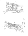
- FIG. 1a two detail enlargements of the seat 30 are shown, in which the upholstery of the back 31 and the seat part 32 is not mounted, so the backrest structure 3 and the lateral attachment of the fan 1 to the backrest structure 3 is better visible.
- FIG. 2 two detailed views of an air supply opening of the air conditioning seat 30 are shown.
- the air supply opening comprises a grid 4 and a funnel 2.
- the air supply opening 2, 4 is connected to the fan 1 and in the example laterally at the in FIG. 2 Not illustrated backrest structure 3 attached.
- the funnel 2 is optimized for ventilation purposes.
- the fan is provided as a blowing fan 1, wherein the fan 1 sucks air through the air supply opening 2, 4 and blows into the air duct 5.
- the grid 4 may also be provided as an air-permeable fabric or, in addition to the grid 4, an air-permeable fabric may be provided at the air supply opening 2, 4, in particular for "pre-filtering" the air blown into the air channel 5.
- a sucking fan instead of a blowing fan; it would only rotate the operating direction of the fan.
- only one fan 1 or a fan module is attached laterally to the backrest structure 3 or to the backrest upholstery.
- This lateral arrangement - similar to an airbag module - makes it possible to have a climate seat 30 with a very small overall depth - i. the depth of the backrest 31 and the seat part 32 - to realize.
- the fan 1 according to the invention can also be positioned laterally on the seat part structure. The air flows in both cases in the air duct 5 approximately parallel to the effective area 71, i.
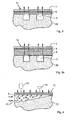
- FIGS. 3 and 3a two sectional views for illustrating two alternative construction variants of the air conditioning seat 30 between the air duct 5 and the effective area 71 are shown.
- the air channel 5 is divided according to the invention, starting from the air supply opening 2, 4 in a plurality of air channel arms.
- each two such air duct arms shown as sections of the air duct 5 in cross section.
- the shape of the air duct 5 and its air duct arms is inventively achieved, for example, that a foam material 51 is given a corresponding shape such that the air channel 5 forms when the foam material 51 is covered by further layers of material.
- a foam material 51 is given a corresponding shape such that the air channel 5 forms when the foam material 51 is covered by further layers of material.
- an air-permeable and perforated layer 6 is provided in the example, the seat heater 6 of the seat 30 is housed. Above the seat heating 6, an air-permeable upper 7 or a top fabric 7 of the seat 30 is provided. With this structure of the seat 30 a very good climate performance is possible.
- an air distribution layer 8 for example, rubber hair or spacer knitted provided that supports the fine distribution of the air.
- the air channel 5 is provided in its air channel arms very slender or branched.
- the seat heating 6 receiving layer 6 is to be realized by means of an air-permeable and perforated non-woven or a corresponding other material.
- the seat heater 6 or the replacement layer 6 should be glued to the foam top of the foam material 51 to form a supporting layer 6 over the air channels.
- This "bridge effect" is necessary in order to avoid a collapse of the upper fabric 7 in the air duct 5 or its air duct arms.
- the "bridge effect" can be supported by the use of rubber hair, in particular in an air distribution layer 8.
- FIGS. 4 . 4a are sectional views of a portion of an air duct 5 along the flow direction of the air in the air duct 5 in two alternative embodiments of the air duct 5 shown.
- the air conditioning seat 30 With sufficient cooling capacity and with only a single fan 1, it is necessary to optimize the air duct 5 fluidly.
- the arms of the air channel 5 are formed so that the back pressure in the arms continuously increases and thus a portion of the air flows to the seat surface 71.
- the layer structure above the air channel 5 is in FIG. 4 and 4a only schematically and without reference numerals of the air duct 5 covering layer shown.
- the increase of the back pressure in the air duct 5 is achieved according to the invention in particular in that the cross section of the air duct 5 in the air duct arms in a direction starting from the air supply opening 2, 4 towards the effective surface 71 - ie in FIG. 4 Direction of flow of the air marked with arrows 52 of the air flow - is continuously reduced.
- FIG. 4 For example, two different sized cross-sectional areas 53, 54 of the air channel 5 are shown at different points of the air channel 5 along the flow direction of the air.
- This reduction of the cross section of the air channel 5 is at an in FIG. 4 in the air duct arms, achieved in particular by the fact that the height of the air duct 5 is reduced in the flow direction of the air and the width is maintained.
- FIG. 4a a second embodiment of an arm of the air channel 5 is shown.
- the top of the air duct 5 is partially closed in its air duct arms with a fleece and opened only at certain intervals upwards.
- the air duct 5 closing points are in FIG. 4a provided with the reference numeral 12.
- an air-permeable cover layer 15 or padding 15 is provided.
- the reference numeral 14 is that surface of a user, for example, his buttock surface, referred to, which touches the effective surface 71 of the seat 30.
- the pressure in the air duct 5 increases.
- the pressure resistance of the padding 15 is smaller than the pressure resistance in the air duct 5, the air is guided in the direction of the seat surface.
- FIG. 4b a plan view of the second embodiment of the air duct 5 in the state occupied by a user 14 shown.
- FIG. 5 an example of an operating unit 40 for controlling the air conditioning seat 30 is shown.
- a display 41 of the vehicle interior temperature is shown and on the right side a setting 42 for the temperature of the seat 30 is provided, wherein the vehicle interior temperature and vehicle seat temperature usually have a certain temperature difference - usually the vehicle interior temperature is about 21 ° C and the vehicle seat temperature about 14 ° C above - and wherein the vehicle seat temperature is adjustable according to the wishes of the user within certain limits.
- FIG. 6 is a temperature diagram for a cooling curve of a vehicle with a climate seat 30 shown in FIG. 7 is a diagram of the fan speed and in FIG. 8 a heat flow diagram shown.
- the diagrams are arranged one below the other in the stated sequence and represent time profiles of the temperature 410, the fan speed 420 and the heat flow 430.
- the axis designated by the reference numeral 400 is therefore a time axis.
- the time starting point of the diagrams is in each case provided with the reference numeral 401 and represents the state of a vehicle overheated, for example, by strong sunlight
- FIG. 6 an interior temperature curve 412 and a seat temperature curve 413 are shown.
- the interior is cooled, for example, by an air conditioner, not shown, so that in the course of time 400 of the FIG. 6 a reduction of the interior temperature 412 results.
- the Climatic seat 30 according to the invention and in particular its fan 1 is strongly activated which is indicated by a comparatively high first fan speed 422 during a cooling phase designated by the reference numeral 402 in all diagrams. Due to the effect of the comparatively large first fan speed 422, during the cooling phase 402, the heat transport power 430 or the heat flow 430 from the seat 30 to the user of the seat 30 drops sharply until it has dropped to about zero at the end of the cooling phase 402, ie there is no heating more of the user through the seat 30 instead.
- the fan speed 420 Upon reaching a comfort temperature range around an interior comfort temperature 414 for the interior, or about a comfort seat temperature 415 for the seat 30, which is also approximately at the end of the cool down phase 402, the fan speed 420 increases from its first value 422 a second fan speed 423 reduced. As a result of the time profile 400, the fan speed 420 can only vary in the range 424 of the second fan speed 423 as long as the interior comfort temperature is not substantially exceeded by the interior temperature (for example due to renewed solar radiation when the air conditioning is switched off). The exclusive variation of the fan speed 420 in the region 424 of the second fan speed 423 is done in order to prevent excessive cooling or hypothermia of a user of the seat 30.
- a user of the seat 30 is allowed to vary the seat temperature within a given range by varying the heat transfer performance of the seat 30 and thus varying the heat flow 430.
- a variation of the heat transport performance can also be done on the basis of a sensor signal coming from an in FIG. 13 416 is derived from the sunlight sensor.
- This variation of the heat transfer performance of the seat 30 is accomplished according to the invention, in particular via a variation of the strength of the air flow in the air duct 5 of the seat 30, which is provided in particular by a variation of the fan speed in the region 424 around the second fan speed 423.
- the first fan speed 422 corresponds to a first level of air flow in the air duct 5 and the second fan speed 423 corresponds to a second level of air flow in the air duct 5 of the seat 30.
- the vehicle interior temperature is generally set in FIG FIG. 13 shown temperature sensor 411 controlled.
- the sensor 411 is in particular in the vehicle center console or at the A or B pillar arranged. This sensor 411 determines the current vehicle interior temperature, the so-called actual vehicle temperature, which is compared with the desired vehicle interior temperature set via the operating unit 40, the so-called vehicle target temperature.
- the unillustrated air conditioning system of the vehicle is then controlled by means of these temperature values.
- FIG. 9 is the backrest 31 of a vehicle seat 30 according to the invention with the fan 1 and the connecting element 9 and the distribution section 100 for the supply of in FIG. 9 Not shown seat part shown.
- FIG. 10 a vehicle seat 30 according to the invention is shown with various possibilities for installing fans 1 or fan modules.
- a fan module 10, 11 can be installed in the seat according to the invention, wherein the fan module 10, 11 includes, for example, either a fan or two fans.
- the air supply opening 2, 4 must then be adapted to the respective case in the rule.
- the fan module 10, 11 is inventively flanged in modular design laterally to the seat 30 and covered with a grid provided for example as a grid 4.
- FIG. 10 which can be seen in the areas of the effective area 71 branching air channel arms of the air channel 5.
- FIGS. 11 and 12 two sectional views of arms of the air duct 5 are shown to illustrate the effect of compensation elements 13, which counteract a reduction in the cross section of the air duct 5 under load of the effective area 71 of the air conditioning seat. Since the reduction in cross section of the air ducts 5 in the occupied state by the load by a user 14 leads to an increase in the pressure loss, a reduction in the cross section of the air ducts should be avoided as far as possible.
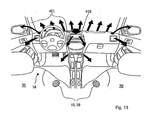
- FIG. 13 is a schematic representation of a vehicle interior with two climate seats 30 according to the invention shown to illustrate air movements.
- the fan modules 10, 11 are in FIG. 13 arranged laterally on the backs of two juxtaposed vehicle seats 30.
- the fan modules 10, 11 are preferably arranged on the vehicle interior side of the seats 30, ie the side of the seats 30 which faces into the vehicle interior.
- On the outer sides of the vehicle seats for example, airbag modules are provided, so that the attachment of the fan modules 10, 11 on the inside of the seats 30 avoids space problems.
- a fan 1 or a fan module 10, 11 may also be provided on the outside.
- the fan 1 attached to the backrest 31 ventilates the backrest 31, and the fan 1 attached to the seated part 32 ventilates the seat part 32.
- the cool air provided by the vehicle air conditioner becomes from the in FIG. 13 merely provided with arrows air nozzles to the air supply opening 2, 4 of the seat 30 and from there to the effective surface 71, in particular to the seat surface, transported.
- This cooling of the seat surface allows heat flow from the occupant into the seat.
- the provision of cold air for the seat cooling in an arrangement of the fan 1 under the seat 30 and in an encapsulated region of the back 31 would be possible later. Due to the resulting close link between the vehicle interior temperature and the vehicle seat temperature, the environmental performance of the seat 30 can be controlled in a particularly simple manner via the vehicle interior temperature. As described above, so that the fan power or the fan speed of the seat 30 via the existing in the vehicle usually air conditioning are easily controlled, so that a user of the vehicle sits in a comfortable temperature range and health-damaging hypothermia are not possible.
- the temperature sensor 411 and the sunlight sensor 416 constantly measure the thermal load present in a vehicle and compare it with the desired vehicle interior temperature. If the actual value of the vehicle interior temperature is greater than the target value, the performance of the air conditioning system is increased, i. it is transported more or colder air inside the vehicle.
- a parked vehicle In a parked vehicle, it is particularly by a strong sunlight to a heating of the vehicle interior, ie an increase in the vehicle interior temperature, and especially to a heating of the seat surfaces.
- a temperature stratification forms in the vehicle interior, wherein it is warmer in the headliner area than in the floor area of the vehicle.
- the temperature of the seat surface - and to a greater extent in particular black leather cover the seat surface - is very high when exposed to sunlight, especially direct sunlight. Even with a parked vehicle now this seat surface temperature is to be reduced. If certain limit values for the interior temperature measured by the temperature sensor 411 are exceeded or if the sunlight sensor 416 measures high solar radiation, it is provided that the fan 1 of the air-conditioning seat starts.
Abstract
Description
Die Erfindung betrifft einen Fahrzeugsitz nach dem Oberbegriff der nebengeordneten Ansprüche. Insbesondere Kraftfahrzeuge werden zunehmend mit Komfortfunktionen ausgerüstet, damit deren Benutzung, beispielsweise bei hohen Außentemperaturen und/oder großer Sonneneinstrahlung, erleichtert wird.The invention relates to a vehicle seat according to the preamble of the independent claims. In particular motor vehicles are increasingly equipped with comfort functions, so that their use, for example, at high outside temperatures and / or high solar radiation, is facilitated.
Allgemein bekannt ist die Verwendung von sogenannten Klimasitzen in Kraftfahrzeugen, die derart vorgesehen sind, dass Nutzungsflächen, d.h. in der Regel solche Flächen, die ein Benutzer beispielsweise durch Aufsetzen bzw. Anlehnen berührt, in ihrer Oberflächentemperatur wählbar vorgesehen sind und insbesondere eine Abkühlung bzw. Erwärmung der Nutzungsflächen erlauben. Hierbei wird eine Abkühlung der Nutzflächen dadurch bewerkstelligt, dass ein Luftstrom in einem Luftkanal im Fahrzeugsitz eingerichtet wird, der dafür sorgt, dass Wärme von der Oberfläche der Nutzflächen abgeführt wird.Commonly known is the use of so-called climate seats in motor vehicles, which are provided such that use areas, i. As a rule, such surfaces, which touches a user, for example by placing or leaning, are provided selectable in their surface temperature and in particular allow a cooling or heating of the land. In this case, a cooling of the usable surfaces is accomplished by an air flow is established in an air duct in the vehicle seat, which ensures that heat is dissipated from the surface of the effective areas.
Beispielsweise aus der deutschen Gebrauchsmusterschrift
Der Erfindung liegt daher die Aufgabe zugrunde einen temperatureinstellbaren Fahrzeugsitz zu schaffen, der einen sehr kleinen Bauraum bzw. eine sehr kleine Bautiefe - insbesondere hinsichtlich der Dicke seiner Lehne und hinsichtlich der Bauhöhe seines Sitzunterbaus - aufweist. Weiterhin soll bei in der Regel vorhandener Klimaanlage im Fahrzeug die klimatisierte Luft auf möglichst direktem Weg vom Fahrzeuginneren zur Abkühlung Sitzflächen des Klimasitzes transportiert werden. Eine weitere Aufgabe besteht darin, die die Nutzflächen abkühlende Luft möglichst ohne eine zusätzliche Luftverteilschicht an die gesamte zu kühlende Oberfläche zu bringen, was weiter die Bautiefe des Sitzes verringert. Weiterhin soll der Klimasitz derart betrieben werden, dass einerseits eine schnelle Abkühlung möglich ist, andererseits jedoch im "Normalbetrieb" eines auf "Komforttemperatur" befindlichen Fahrzeuginnenraums keine zu große Kühlleistung möglich ist, so dass eine für einen Benutzer möglicherweise schädliche Unterkühlung weitgehend vermieden wird.The invention is therefore an object of the invention to provide a temperature-adjustable vehicle seat, which has a very small space or a very small depth - especially in terms of the thickness of his backrest and in terms of the height of his seat base - has. Furthermore, the air-conditioned air is to be transported as far as possible directly from the vehicle interior to cool seats of the air-conditioning seat in usually existing air conditioning in the vehicle. Another object is to bring the air cooling the useful surfaces as possible without an additional Luftverteilschicht to the entire surface to be cooled, which further reduces the depth of the seat. Continue to the air conditioning seat are operated so that on the one hand a rapid cooling is possible, on the other hand, however, in the "normal operation" of a "comfort temperature" located vehicle interior no excessive cooling capacity is possible, so that a potentially harmful to a user hypothermia is largely avoided.
Diese Aufgaben werden erfindungsgemäß durch einen Fahrzeugsitz gemäß den nebengeordneten Ansprüchen gelöst. Hierzu ist zum einen ein Fahrzeugsitz mit einem Ventilator, einer Nutzfläche und einer Luftversorgungsöffnung vorgesehen, bei dem der Ventilator in einem zwischen der Nutzfläche und der Luftverteilöffnung befindlichen und sich in wenigstens zwei Luftkanalarme teilenden Luftkanal eine gerichtete Luftströmung herstellt, wobei der Ventilator bei in Fahrtrichtung des Fahrzeugs ausgerichtetem Fahrzeugsitz an der Seite des Fahrzeugsitzes angeordnet vorgesehen ist. Weiterhin ist ein Fahrzeugsitz mit einer Nutzfläche und einer Luftversorgungsöffnung vorgesehen, wobei die Nutzfläche mit der Luftversorgungsöffnung über wenigstens einen Luftkanal verbunden ist, wobei in dem Luftkanal eine gerichtete Luftströmung vorgesehen ist, wobei in einer Richtung ausgehend von der Luftversorgungsöffnung hin zur Nutzfläche eine Verkleinerung des Querschnitts des Luftkanals vorgesehen ist.These objects are achieved by a vehicle seat according to the independent claims. For this purpose, on the one hand, a vehicle seat with a fan, a usable surface and an air supply opening is provided, in which the fan produces a directed air flow in an air duct situated between the useful surface and the air distribution opening and dividing into at least two air duct arms, the fan being directed in the direction of travel Vehicle-oriented vehicle seat is provided on the side of the vehicle seat arranged. Furthermore, a vehicle seat with a useful surface and an air supply opening is provided, wherein the useful surface is connected to the air supply opening via at least one air duct, wherein in the air duct a directed air flow is provided, wherein in a direction starting from the air supply opening to the effective area a reduction of the cross section the air duct is provided.
Ein weiterer Gegenstand der vorliegenden Erfindung ist ein Verfahren zur Steuerung der Stärke der Wärmetransportleistung einer Luftströmung in einem Luftkanal eines Fahrzeugsitzes, der in einem Fahrzeug eingesetzt wird, wobei die Wärmetransportleistung der Luftströmung in Abhängigkeit davon vorgesehen ist, ob eine gemessene Fahrzeugisttemperatur im Inneren des Fahrzeugs oberhalb einer vorgegebenen Fahrzeugsolltemperatur liegt. Hierdurch kann die Klimaleistung des Sitzes vorteilhafterweise über die Fahrzeuginnentemperatur gesteuert werden. Bevorzugt ist eine Ausführungsform vorgesehen, bei der die Stärke der Luftströmung als Maß für die Stärke der Wärmetransportleistung der Luftströmung verwendet wird. Dies ist vorteilhaft, weil die Stärke der Luftströmung eine besonders einfach zugängliche Größe mit - zusammen mit der maßgebenden Temperaturdifferenz - Einfluss auf die Wärmetransportleistung ist. Bevorzugt ist weiterhin eine Ausführungsform des Verfahrens, bei der zwei unterschiedlich starke Luftströmungen möglich sind, wobei die stärkere Luftströmung lediglich für den Fall einer deutlichen Überschreitung der Fahrzeugsolltemperatur durch die Fahrzeugisttemperatur eingestellt wird und wobei für den Fall, dass die Fahrzeugisttemperatur im Bereich der Fahrzeugsolltemperatur liegt, nur Luftströmungsstärken eingestellt werden können, die im Bereich der schwächeren der zwei unterschiedlich starken Luftströmungen liegen. Dadurch werden vorteilhafterweise gesundheitsbeeinträchtigende Unterkühlungen von Benutzern des Fahrzeugssitzes vermieden.Another object of the present invention is a method for controlling the strength of the heat transfer performance of an air flow in an air duct of a vehicle seat, which is used in a vehicle, wherein the heat transport performance of the air flow is provided depending on whether a measured vehicle actual temperature inside the vehicle above a predetermined vehicle target temperature is. As a result, the climatic performance of the seat can advantageously be controlled via the vehicle interior temperature. Preferably, an embodiment is provided in which the strength of the air flow is used as a measure of the strength of the heat transfer performance of the air flow. This is advantageous because the strength of the air flow is a particularly easily accessible quantity with - together with the relevant temperature difference - influence on the heat transfer performance. Also preferred is an embodiment of the method in which two different strong air flows are possible, wherein the stronger air flow only in the event of a significant excess of the Set vehicle setpoint by the vehicle's actual temperature and wherein in the event that the vehicle's actual temperature is in the range of the target vehicle temperature, only air currents can be set, which are in the range of the weaker of the two different strong air currents. As a result, health-damaging sub-cooling of users of the vehicle seat are advantageously avoided.
Die Erfindung wird nachfolgend anhand von in der Zeichnung dargestellten Ausführungsbeispielen näher erläutert. Es zeigen
Figuren 1 und 1 a- einen erfindungsgemäßen Fahrzeugsitz in einer perspektivischen Darstellung mit Detailvergrößerungen,
Figur 2- zwei Detailansichten einer Luftversorgungsöffnung des Klimasitzes,
Figuren 3 und 3a- zwei Schnittdarstellungen zur Veranschaulichung zweier alternativer Aufbauvarianten des Klimasitzes zwischen dem Luftkanal und der Nutzfläche,
Figuren 4, 4a, 4b- Schnittdarstellungen eines Teils eines Luftkanals in zwei alternativen Ausführungsformen des Luftkanals und eine Draufsicht auf die zweite Ausführungsform des Luftkanals im Zustand "besetzt",
Figur 5- ein Beispiel für eine Bedieneinheit zur Regelung des Klimasitzes,
Figuren - ein Temperaturdiagramm, ein Diagramm der Lüfterdrehzahl und ein Wärmestromdiagramm,
Figur 9- die Rückenlehne eines erfindungsgemäßen Fahrzeugsitzes,
Figur 10- einen erfindungsgemäßen Fahrzeugsitz mit verschiedenen Möglichkeiten einbaubarer Ventilatoren,
Figuren 11 und 12- zwei Schnittdarstellungen zur Veranschaulichung von Kompensationselementen, die einer Verringerung des Querschnitts des Luftkanals bei Belastung der Nutzfläche des Klimasitzes entgegenwirken und
Figur 13- eine schematische Darstellung eines Fahrzeuginnenraums mit zwei erfindungsgemäßen Klimasitzen zur Veranschaulichung von Luftbewegungen.
- FIGS. 1 and 1 a
- a vehicle seat according to the invention in a perspective view with detail enlargements,
- FIG. 2
- two detailed views of an air supply opening of the climate seat,
- FIGS. 3 and 3a
- two sectional views for illustrating two alternative construction variants of the air-conditioning seat between the air duct and the usable area,
- FIGS. 4, 4a, 4b
- Sectional views of a part of an air duct in two alternative embodiments of the air duct and a plan view of the second embodiment of the air duct in the state "occupied",
- FIG. 5
- an example of an operating unit for controlling the air conditioning seat,
- FIGS. 6, 7 and 8
- a temperature diagram, a diagram of the fan speed and a heat flow diagram,
- FIG. 9
- the backrest of a vehicle seat according to the invention,
- FIG. 10
- a vehicle seat according to the invention with different possibilities of installable fans,
- FIGS. 11 and 12
- two sectional views illustrating compensation elements, which counteract a reduction in the cross section of the air duct under load of the effective area of the air-conditioning seat and
- FIG. 13
- a schematic representation of a vehicle interior with two climate seats according to the invention for the purpose of illustrating air movements.
In
In
Im dargestellten Ausführungsbeispiel ist lediglich ein Lüfter 1 bzw. ein Lüftermodul seitlich an der Lehnenstruktur 3 oder auch an der Lehnenpolsterung befestigt. Diese seitliche Anordnung - ähnlich einem Airbagmodul - ermöglicht es, einen Klimasitz 30 mit einer sehr geringen Bautiefe - d.h. der Bautiefe der Lehne 31 bzw. des Sitzteils 32 - zu realisieren. Der Lüfter 1 kann erfindungsgemäß auch seitlich an der Sitzteilstruktur positioniert sein. Die Luft strömt in beiden Fällen im Luftkanal 5 annähernd parallel zur Nutzfläche 71, d.h. beispielsweise zur Sitzfläche für das Sitzteil 32, in den Sitz 30 ein und vermindert so Strömungsverluste, so dass die Verwendung eines - im Vergleich zu einer im wesentlichen senkrechten Einströmrichtung relativ zur jeweiligen Nutzfläche 71 - kleineren Lüfters 1 bzw. die Verwendung einer geringeren Anzahl von Lüftern 1 möglich wird. Durch diese Art der Anströmung wird auch das akustische Problem verringert bzw. gelöst, das durch die unterschiedliche Belastung des Sitzes 30 zwischen dem Zustand "besetzt" und dem Zustand "unbesetzt" des Sitzes 30 entsteht. Es ist nämlich so, dass bei einer weitgehend senkrechten Anströmung der jeweiligen Nutzfläche 71, d.h. der Luftstrom wird vom Lüfter 1 direkt zur Nutzfläche 71, d.h. beispielsweise der Sitzfläche, geführt, starke Schwankungen des Luftwiderstandes im Luftkanal zwischen unbesetztem und besetztem Sitz 30 entstehen, die zu unangenehmen und störenden Geräuschen führen.In the illustrated embodiment, only one
In den
In den
In
In
In
In
In
In den
In
Diese Kühlung der Sitzoberfläche ermöglicht einen Wärmestrom vom Insassen weg in den Sitz hinein. Durch die Anordnung des Lüfters 1 bzw. des Lüftermoduls 10, 11 seitlich am Sitz 30 auf der Innenseite des Fahrgastraums des Fahrzeugs kann die kühle und entfeuchtete Luft aus der Klimaanlage, welche die Temperatur im Fahrzeuginnenraum verringert, in besonders einfacher und direkter Weise in den Sitz und somit dem Benutzer zugeführt werden. Demgegenüber wäre die Bereitstellung der kalten Luft für die Sitzkühlung bei einer Anordnung des Lüfters 1 unter dem Sitz 30 bzw. in einem gekapselten Bereich der Lehne 31 erst später möglich. Durch die sich daraus ergebende enge Verknüpfung zwischen der Fahrzeuginnentemperatur und der Fahrzeugsitztemperatur lässt sich die Klimaleistung des Sitzes 30 über die Fahrzeuginnentemperatur in besonders einfacher Weise steuern. Wie oben beschrieben kann damit die Lüfterleistung bzw. die Lüfterdrehzahl des Sitzes 30 über die im Fahrzeug in der Regel vorhandene Klimaanlage in einfacher Weise geregelt werden, so dass ein Benutzer des Fahrzeugs im komfortablen Temperaturbereich sitzt und gesundheitsbeeinträchtigende Unterkühlungen nicht möglich sind.This cooling of the seat surface allows heat flow from the occupant into the seat. The arrangement of the
Der Temperatursensor 411 und der Sonnenlichtsensor 416 messen ständig die in einem Fahrzeug vorhandene thermische Belastung und gleichen diese mit der gewünschten Fahrzeuginnenraumtemperatur ab. Ist der Ist-Wert der Fahrzeuginnentemperatur größer als der Soll-Wert wird die Leistung der Klimaanlage erhöht, d.h. es wird mehr bzw. kältere Luft ins Fahrzeuginnere transportiert.The
Bei einem parkenden Fahrzeug kommt es besonders durch eine starke Sonneneinstrahlung zu einer Aufheizung des Fahrzeuginnenraums, d.h. einer Erhöhung der Fahrzeuginnenraumtemperatur, und besonders zu einer Aufheizung der Sitzoberflächen. Bei dieser Aufheizung bildet sich eine Temperaturschichtung im Fahrzeuginnenraum aus, wobei es im Dachhimmelbereich wärmer ist als im Bodenbereich des Fahrzeugs. Besonders die Temperatur der Sitzoberfläche - und in verstärktem Maße bei insbesondere schwarzem Lederbezug der Sitzoberfläche - wird bei Einwirkung von Sonneneinstrahlung, insbesondere direkter Sonneneinstrahlung, sehr hoch. Auch bei einem parkenden Fahrzeug soll nun diese Sitzoberflächentemperatur reduziert werden. Bei einer Überschreitung gewisser Grenzwerte für die durch den Temperatursensor 411 gemessenen Innenraumtemperatur bzw. bei Messung einer hohen Sonneneinstrahlung durch den Sonnenlichtsensor 416 ist es vorgesehen, dass der Lüfter 1 des Klimasitzes anläuft. Durch die im Vergleich zur hohen Sitzoberflächentemperatur geringen Lufttemperatur im Bereich des Lüfters, wird der heißen Sitzoberfläche Wärme entzogen und die Sitzoberflächentemperatur sinkt. Dieser Kühleffekt ist besonders wirksam, wenn auch beim parkenden Fahrzeug in solchen Situationen die Klimanlage oder ein anderes Kühlaggregat aktiviert wird und dadurch gekühlte Luft im Innenraum des Fahrzeugs zur Verfügung gestellt wird.In a parked vehicle, it is particularly by a strong sunlight to a heating of the vehicle interior, ie an increase in the vehicle interior temperature, and especially to a heating of the seat surfaces. During this heating, a temperature stratification forms in the vehicle interior, wherein it is warmer in the headliner area than in the floor area of the vehicle. In particular, the temperature of the seat surface - and to a greater extent in particular black leather cover the seat surface - is very high when exposed to sunlight, especially direct sunlight. Even with a parked vehicle now this seat surface temperature is to be reduced. If certain limit values for the interior temperature measured by the
- 11
- LüfterFan
- 2, 42, 4
- LuftversorgungsöffnungAir supply opening
- 33
- Lehnenstrukturback structure
- 55
- Luftkanalair duct
- 5a5a
- DruckbegrenzungsabschnittPressure relief section
- 66
- SitzheizungHeated seats
- 77
- Oberwaretop web
- 88th
- LuftverteilschichtLuftverteilschicht
- 99
- Verbindungselementconnecting element
- 10, 1110, 11
- Lüftermodulfan module
- 1212
- Verschließende StellenClosing posts
- 1313
- Kompensationselementecompensation elements
- 1414
- Benutzeruser
- 1515
- Polsterungupholstery
- 3030
- Fahrzeugsitzvehicle seat
- 3131
- Lehnerest
- 3232
- Sitzteilseat part
- 4040
- Bedieneinheitoperating unit
- 4141
- Anzeigedisplay
- 4242
- Einstellmöglichkeit für die Temperatur des SitzesAdjustment for the temperature of the seat
- 5151
- Schaumstoffmaterialfoam material
- 5252
- Strömungsrichtung der LuftFlow direction of the air
- 53, 5453, 54
- QuerschnittsflächenCross-sectional areas
- 7171
- NutzflächeUsable area
- 7272
- nicht als Sitzfläche benutzter Bereichnot used as seating area
- 100100
- VerteilungsabschniftVerteilungsabschnift
- 400400
- Zeitachsetimeline
- 401401
- zeitlicher Startpunkttime starting point
- 402402
- Abkühlphasecooling phase
- 410410
- Temperaturtemperature
- 411411
- Temperatursensortemperature sensor
- 412412
- InnenraumtemperaturkurveInterior temperature curve
- 413413
- SitztemperaturkurveSeat temperature curve
- 414414
- InnenraumkomforttemperaturInterior comfort temperature
- 415415
- SitzkomforttemperaturComfort temperature
- 416416
- SonnenlichtsensorSunlight sensor
- 420420
- LüfterdrehzahlFan speed
- 422422
- erste Lüfterdrehzahlfirst fan speed
- 423423
- zweite Lüfterdrehzahlsecond fan speed
- 424424
- um die zweite Lüfterdrehzahl vorgesehener Bereichrange provided around the second fan speed
- 430430
- Wärmestromheat flow
Claims (16)
Applications Claiming Priority (2)
| Application Number | Priority Date | Filing Date | Title |
|---|---|---|---|
| DE10316275A DE10316275B4 (en) | 2003-04-08 | 2003-04-08 | vehicle seat |
| EP04726129A EP1613503A1 (en) | 2003-04-08 | 2004-04-07 | Vehicle seat |
Related Parent Applications (1)
| Application Number | Title | Priority Date | Filing Date |
|---|---|---|---|
| EP04726129.2 Division | 2004-04-07 |
Publications (2)
| Publication Number | Publication Date |
|---|---|
| EP2363318A2 true EP2363318A2 (en) | 2011-09-07 |
| EP2363318A3 EP2363318A3 (en) | 2012-01-11 |
Family
ID=33154137
Family Applications (3)
| Application Number | Title | Priority Date | Filing Date |
|---|---|---|---|
| EP04726129A Withdrawn EP1613503A1 (en) | 2003-04-08 | 2004-04-07 | Vehicle seat |
| EP11003557A Withdrawn EP2363318A3 (en) | 2003-04-08 | 2004-04-07 | Vehicle seat |
| EP11003581A Withdrawn EP2360052A3 (en) | 2003-04-08 | 2004-04-07 | Vehicle seat |
Family Applications Before (1)
| Application Number | Title | Priority Date | Filing Date |
|---|---|---|---|
| EP04726129A Withdrawn EP1613503A1 (en) | 2003-04-08 | 2004-04-07 | Vehicle seat |
Family Applications After (1)
| Application Number | Title | Priority Date | Filing Date |
|---|---|---|---|
| EP11003581A Withdrawn EP2360052A3 (en) | 2003-04-08 | 2004-04-07 | Vehicle seat |
Country Status (6)
| Country | Link |
|---|---|
| US (1) | US7467823B2 (en) |
| EP (3) | EP1613503A1 (en) |
| JP (1) | JP2006524159A (en) |
| CN (1) | CN100480095C (en) |
| DE (1) | DE10316275B4 (en) |
| WO (1) | WO2004089689A1 (en) |
Families Citing this family (131)
| Publication number | Priority date | Publication date | Assignee | Title |
|---|---|---|---|---|
| DE102004030705B3 (en) * | 2004-06-25 | 2005-12-01 | Daimlerchrysler Ag | Air supply device for a vehicle seat and method for operating the same |
| DE102005014333B4 (en) * | 2005-03-24 | 2009-11-05 | W.E.T. Automotive Systems Ag | Air-conditioned seat and air conditioning unit |
| DE102005015239A1 (en) * | 2005-04-02 | 2006-10-19 | Gottlieb Binder Gmbh & Co. Kg | Fastening device and method for producing the same |
| US20070200398A1 (en) * | 2006-02-28 | 2007-08-30 | Scott Richard Wolas | Climate controlled seat |
| DE102006016091B4 (en) * | 2006-04-04 | 2009-10-01 | Johnson Controls Gmbh | Vehicle seat with an air outlet opening on the back of the backrest part |
| DE502006003779D1 (en) * | 2006-11-06 | 2009-07-02 | Eberspaecher Catem Gmbh & Co K | Blower module for a vehicle seat and motor vehicle seat with noise insulation |
| US7823967B2 (en) * | 2007-03-26 | 2010-11-02 | Emteq, Inc. | Heater system for an aircraft seat |
| DE202007008310U1 (en) * | 2007-06-14 | 2008-10-23 | Brose Fahrzeugteile Gmbh & Co. Kommanditgesellschaft, Coburg | Vehicle seat with an air conditioning device |
| JP5251018B2 (en) * | 2007-07-04 | 2013-07-31 | トヨタ紡織株式会社 | Breathable cushion and method for manufacturing the same |
| DE102007035373A1 (en) * | 2007-07-25 | 2009-01-29 | Sitech Sitztechnik Gmbh | Runtime behavior of a fan for an active climate seat |
| DE102007042426A1 (en) * | 2007-09-06 | 2009-03-12 | Bayerische Motoren Werke Aktiengesellschaft | Vehicle seat comprises seat part and backrest part that are ventilated by ventilation device, which is integrated into vehicle seat, where air distribution element is arranged in seat part or in backrest part |
| US20100133883A1 (en) * | 2008-01-29 | 2010-06-03 | Georgia Bell Walker | Infant and Toddler Car Seat with integral cooling system / humidifier |
| DE102008025855B3 (en) * | 2008-05-29 | 2009-11-12 | Daimler Ag | Motor vehicle seat has backrest and two side carriages which are attached at opposite side of backrest, where head space ventilation unit is provided for supplying head, neck and shoulder area of passenger |
| DE102008038380B4 (en) * | 2008-08-19 | 2010-11-11 | Lear Corp., Southfield | Alignment system for a spacer layer in a ventilated seat |
| DE202009017049U1 (en) | 2008-12-21 | 2010-05-12 | W.E.T. Automotive Systems Ag | aerator |
| US20120080911A1 (en) * | 2010-08-27 | 2012-04-05 | Amerigon Incorporated | Fluid distribution features for climate controlled seating assemblies |
| US20120153701A1 (en) * | 2010-12-21 | 2012-06-21 | Chen-Chang Lin | Ventilative vehicle seat back |
| GB2496166A (en) * | 2011-11-03 | 2013-05-08 | Trappeng Ltd | Cushion including ventilation apparatus and ventilation apparatus |
| JP6002409B2 (en) * | 2012-03-22 | 2016-10-05 | 富士重工業株式会社 | Seat device, air blower for seat, and vehicle |
| DE102012022157A1 (en) * | 2012-05-29 | 2013-12-05 | Johnson Controls Gmbh | Vehicle seat, in particular motor vehicle seat with an air conditioning system |
| JP6102134B2 (en) * | 2012-09-18 | 2017-03-29 | 株式会社デンソー | Vehicle seat air conditioner |
| DE102012019538B4 (en) * | 2012-10-05 | 2015-03-05 | W.E.T. Automotive Systems Ag | Air conditioning device for a vehicle interior and vehicle seat and vehicle |
| CN103010058A (en) * | 2012-12-04 | 2013-04-03 | 陈贺章 | Rapid cooling and heating seat cushion |
| US9126504B2 (en) | 2013-01-24 | 2015-09-08 | Ford Global Technologies, Llc | Integrated thin flex composite headrest assembly |
| US9399418B2 (en) | 2013-01-24 | 2016-07-26 | Ford Global Technologies, Llc | Independent cushion extension and thigh support |
| US9061616B2 (en) | 2013-01-24 | 2015-06-23 | Ford Global Technologies, Llc | Articulating headrest assembly |
| US8727374B1 (en) | 2013-01-24 | 2014-05-20 | Ford Global Technologies, Llc | Vehicle seatback with side airbag deployment |
| US9415713B2 (en) | 2013-01-24 | 2016-08-16 | Ford Global Technologies, Llc | Flexible seatback system |
| US9409504B2 (en) | 2013-01-24 | 2016-08-09 | Ford Global Technologies, Llc | Flexible seatback system |
| US9126508B2 (en) | 2013-01-24 | 2015-09-08 | Ford Global Technologies, Llc | Upper seatback pivot system |
| US9096157B2 (en) | 2013-01-24 | 2015-08-04 | Ford Global Technologies, Llc | Seating assembly with air distribution system |
| US9216677B2 (en) | 2013-01-24 | 2015-12-22 | Ford Global Technologies, Llc | Quick-connect trim carrier attachment |
| US9016784B2 (en) | 2013-01-24 | 2015-04-28 | Ford Global Technologies, Llc | Thin seat leg support system and suspension |
| US9016783B2 (en) | 2013-01-24 | 2015-04-28 | Ford Global Technologies, Llc | Thin seat flex rest composite cushion extension |
| US9902293B2 (en) | 2013-01-24 | 2018-02-27 | Ford Global Technologies, Llc | Independent cushion extension with optimized leg-splay angle |
| US9193284B2 (en) | 2013-06-11 | 2015-11-24 | Ford Global Technologies, Llc | Articulating cushion bolster for ingress/egress |
| DE202013006135U1 (en) * | 2013-07-09 | 2013-07-25 | I.G. Bauerhin Gmbh | Air conditioning device for a vehicle seat |
| FR3010355B1 (en) * | 2013-09-09 | 2017-04-21 | Faurecia Sieges D'automobile | MOTOR VEHICLE SEAT AND METHOD FOR MANAGING THE COMFORT OF SUCH A MOTOR VEHICLE SEAT |
| US9527418B2 (en) | 2013-09-12 | 2016-12-27 | Ford Global Technologies, Llc | Semi rigid push/pull vented envelope system |
| US8905431B1 (en) | 2013-09-24 | 2014-12-09 | Ford Global Technologies, Llc | Side airbag assembly for a vehicle seat |
| US9187019B2 (en) | 2013-10-17 | 2015-11-17 | Ford Global Technologies, Llc | Thigh support for customer accommodation seat |
| DE102013221516A1 (en) * | 2013-10-23 | 2015-04-23 | Bayerische Motoren Werke Aktiengesellschaft | An air supply device for a vehicle seat and method for operating the air supply device |
| US9505322B2 (en) | 2013-10-25 | 2016-11-29 | Ford Global Technologies, Llc | Manual lumbar pump assembly |
| US9566884B2 (en) | 2013-11-11 | 2017-02-14 | Ford Global Technologies, Llc | Powered head restraint electrical connector |
| US9315130B2 (en) | 2013-11-11 | 2016-04-19 | Ford Global Technologies, Llc | Articulating head restraint |
| US9365143B2 (en) | 2013-12-12 | 2016-06-14 | Ford Global Technologies, Llc | Rear seat modular cushion |
| TWM483686U (en) * | 2014-05-02 | 2014-08-11 | Jian-Feng Lin | Vibration breathable chest pad |
| US9315131B2 (en) | 2014-01-23 | 2016-04-19 | Ford Global Technologies, Llc | Suspension seat back and cushion system having an inner suspension panel |
| US9649963B2 (en) | 2014-03-04 | 2017-05-16 | Ford Global Technologies, Pllc | Trim and foam assembly for a vehicle seat |
| CN104943583B (en) | 2014-03-26 | 2020-01-14 | 福特全球技术公司 | Seat climate control assembly and seat thereof |
| JP6317973B2 (en) * | 2014-03-28 | 2018-04-25 | 株式会社Subaru | Seat device and vehicle |
| US9527419B2 (en) | 2014-03-31 | 2016-12-27 | Ford Global Technologies, Llc | Vehicle seating assembly with manual cushion tilt |
| US9302643B2 (en) | 2014-04-02 | 2016-04-05 | Ford Global Technologies, Llc | Vehicle seating assembly with side airbag deployment |
| US9421894B2 (en) | 2014-04-02 | 2016-08-23 | Ford Global Technologies, Llc | Vehicle seating assembly with manual independent thigh supports |
| US10328823B2 (en) | 2014-06-09 | 2019-06-25 | Lear Corporation | Adjustable seat assembly |
| US9987961B2 (en) | 2014-06-09 | 2018-06-05 | Lear Corporation | Adjustable seat assembly |
| US9694741B2 (en) | 2014-08-25 | 2017-07-04 | Ford Global Technologies, Llc | Ambient functional lighting of a seat |
| US10471874B2 (en) | 2014-09-02 | 2019-11-12 | Ford Global Technologies, Llc | Massage bladder matrix |
| US9789790B2 (en) | 2014-10-03 | 2017-10-17 | Ford Global Technologies, Llc | Tuned flexible support member and flexible suspension features for comfort carriers |
| US9333882B2 (en) | 2014-10-03 | 2016-05-10 | Ford Global Technologies, Llc | Manual upper seatback support |
| US9776533B2 (en) | 2014-10-03 | 2017-10-03 | Ford Global Technologies, Llc | Torsion bar upper seatback support assembly |
| US9771003B2 (en) | 2014-10-29 | 2017-09-26 | Ford Global Technologies, Llc | Apparatus for customizing a vehicle seat for an occupant |
| US9340131B1 (en) | 2014-11-06 | 2016-05-17 | Ford Global Technologies, Llc | Head restraint with a multi-cell bladder assembly |
| US9517777B2 (en) | 2014-11-06 | 2016-12-13 | Ford Global Technologies, Llc | Lane departure feedback system |
| US10065570B2 (en) | 2014-12-10 | 2018-09-04 | Ford Global Technologies, Llc | Electronic device holder for a vehicle seat |
| US9593642B2 (en) | 2014-12-19 | 2017-03-14 | Ford Global Technologies, Llc | Composite cam carrier |
| US9663000B2 (en) | 2015-01-16 | 2017-05-30 | Ford Global Technologies, Llc | Vehicle seat configured to improve access |
| US9981577B2 (en) | 2015-01-19 | 2018-05-29 | Lear Corporation | Thoracic air bladder assembly |
| US9707877B2 (en) | 2015-01-20 | 2017-07-18 | Ford Global Technologies, Llc | Independent thigh extension and support trim carrier |
| US9365142B1 (en) | 2015-01-20 | 2016-06-14 | Ford Global Technologies, Llc | Manual independent thigh extensions |
| JP6431403B2 (en) * | 2015-02-20 | 2018-11-28 | 株式会社タチエス | Vehicle seat |
| JP6434818B2 (en) * | 2015-02-13 | 2018-12-05 | 株式会社タチエス | Vehicle seat |
| WO2016129575A1 (en) * | 2015-02-13 | 2016-08-18 | 株式会社タチエス | Vehicular seat |
| JP6423732B2 (en) * | 2015-02-13 | 2018-11-14 | 株式会社タチエス | Vehicle seat |
| KR101655199B1 (en) * | 2015-02-27 | 2016-09-07 | 현대자동차 주식회사 | Ventilation bed and controling method of a vehicle |
| US9566930B2 (en) | 2015-03-02 | 2017-02-14 | Ford Global Technologies, Llc | Vehicle seat assembly with side-impact airbag deployment mechanism |
| US9713975B2 (en) * | 2015-03-31 | 2017-07-25 | Ford Global Technologies, Llc | Vehicle seating assembly having a blower mounted to the seatback against a plastic matrix |
| US9802535B2 (en) | 2015-04-27 | 2017-10-31 | Ford Global Technologies, Llc | Seat having ambient lighting |
| US9884570B2 (en) | 2015-05-19 | 2018-02-06 | Lear Corporation | Adjustable seat assembly |
| US9845026B2 (en) | 2015-05-19 | 2017-12-19 | Lear Corporation | Adjustable seat assembly |
| WO2017011990A1 (en) | 2015-07-21 | 2017-01-26 | Gentherm Automotive Systems (China) Ltd. | Connector for a climate controlled support device |
| US10046682B2 (en) | 2015-08-03 | 2018-08-14 | Ford Global Technologies, Llc | Back cushion module for a vehicle seating assembly |
| US9718387B2 (en) | 2015-08-03 | 2017-08-01 | Ford Global Technologies, Llc | Seat cushion module for a vehicle seating assembly |
| US9688174B2 (en) | 2015-08-07 | 2017-06-27 | Ford Global Technologies, Llc | Multi-cell seat cushion assembly |
| US9573528B1 (en) | 2015-08-25 | 2017-02-21 | Ford Global Technologies, Llc | Integrated seatback storage |
| US9661928B2 (en) | 2015-09-29 | 2017-05-30 | Lear Corporation | Air bladder assembly for seat bottoms of seat assemblies |
| US9616776B1 (en) | 2015-11-16 | 2017-04-11 | Ford Global Technologies, Llc | Integrated power thigh extender |
| US9809131B2 (en) | 2015-12-04 | 2017-11-07 | Ford Global Technologies, Llc | Anthropomorphic pivotable upper seatback support |
| US9931999B2 (en) | 2015-12-17 | 2018-04-03 | Ford Global Technologies, Llc | Back panel lower clip anchorage features for dynamic events |
| US9827888B2 (en) | 2016-01-04 | 2017-11-28 | Lear Corporation | Seat assemblies with adjustable side bolster actuators |
| US10093214B2 (en) | 2016-01-14 | 2018-10-09 | Ford Global Technologies, Llc | Mechanical manual leg tilt |
| US9914421B2 (en) | 2016-01-15 | 2018-03-13 | Ford Global Technologies, Llc | Seatback flexible slip plane joint for side air bag deployment |
| US10052990B2 (en) | 2016-01-25 | 2018-08-21 | Ford Global Technologies, Llc | Extended seatback module head restraint attachment |
| US9776543B2 (en) | 2016-01-25 | 2017-10-03 | Ford Global Technologies, Llc | Integrated independent thigh supports |
| US10035442B2 (en) | 2016-01-25 | 2018-07-31 | Ford Global Technologies, Llc | Adjustable upper seatback module |
| US9756408B2 (en) | 2016-01-25 | 2017-09-05 | Ford Global Technologies, Llc | Integrated sound system |
| US9849817B2 (en) | 2016-03-16 | 2017-12-26 | Ford Global Technologies, Llc | Composite seat structure |
| US10286818B2 (en) | 2016-03-16 | 2019-05-14 | Ford Global Technologies, Llc | Dual suspension seating assembly |
| US10046681B2 (en) | 2016-04-12 | 2018-08-14 | Ford Global Technologies, Llc | Articulating mechanical thigh extension composite trim payout linkage system |
| US9994135B2 (en) | 2016-03-30 | 2018-06-12 | Ford Global Technologies, Llc | Independent cushion thigh support |
| US10220737B2 (en) | 2016-04-01 | 2019-03-05 | Ford Global Technologies, Llc | Kinematic back panel |
| US9889773B2 (en) | 2016-04-04 | 2018-02-13 | Ford Global Technologies, Llc | Anthropomorphic upper seatback |
| US9802512B1 (en) | 2016-04-12 | 2017-10-31 | Ford Global Technologies, Llc | Torsion spring bushing |
| US10081279B2 (en) | 2016-04-12 | 2018-09-25 | Ford Global Technologies, Llc | Articulating thigh extension trim tensioning slider mechanism |
| US10625646B2 (en) | 2016-04-12 | 2020-04-21 | Ford Global Technologies, Llc | Articulating mechanical thigh extension composite trim payout linkage system |
| US9845029B1 (en) | 2016-06-06 | 2017-12-19 | Ford Global Technologies, Llc | Passive conformal seat with hybrid air/liquid cells |
| US9834166B1 (en) | 2016-06-07 | 2017-12-05 | Ford Global Technologies, Llc | Side airbag energy management system |
| US9849856B1 (en) | 2016-06-07 | 2017-12-26 | Ford Global Technologies, Llc | Side airbag energy management system |
| US10166895B2 (en) | 2016-06-09 | 2019-01-01 | Ford Global Technologies, Llc | Seatback comfort carrier |
| US10377279B2 (en) | 2016-06-09 | 2019-08-13 | Ford Global Technologies, Llc | Integrated decking arm support feature |
| US10286824B2 (en) | 2016-08-24 | 2019-05-14 | Ford Global Technologies, Llc | Spreader plate load distribution |
| US10279714B2 (en) | 2016-08-26 | 2019-05-07 | Ford Global Technologies, Llc | Seating assembly with climate control features |
| US10239431B2 (en) | 2016-09-02 | 2019-03-26 | Ford Global Technologies, Llc | Cross-tube attachment hook features for modular assembly and support |
| US10391910B2 (en) | 2016-09-02 | 2019-08-27 | Ford Global Technologies, Llc | Modular assembly cross-tube attachment tab designs and functions |
| JP6652199B2 (en) * | 2016-10-24 | 2020-02-19 | 株式会社デンソー | Ventilation seat and seat air conditioner |
| US9914378B1 (en) | 2016-12-16 | 2018-03-13 | Ford Global Technologies, Llc | Decorative and functional upper seatback closeout assembly |
| JP6665807B2 (en) * | 2017-02-08 | 2020-03-13 | トヨタ自動車株式会社 | Vehicle seat |
| JP6652713B2 (en) * | 2017-03-01 | 2020-02-26 | テイ・エス テック株式会社 | Vehicle seat |
| US11560077B2 (en) | 2017-03-28 | 2023-01-24 | Staels Design Ltd. | Support structure, apparatus and method |
| US10596936B2 (en) | 2017-05-04 | 2020-03-24 | Ford Global Technologies, Llc | Self-retaining elastic strap for vent blower attachment to a back carrier |
| JP6658679B2 (en) * | 2017-06-20 | 2020-03-04 | 株式会社デンソー | Seat air conditioner |
| US11707909B2 (en) * | 2017-10-27 | 2023-07-25 | Gentherm Gmbh | Surface temperature-controlling device |
| US10479243B2 (en) | 2017-12-05 | 2019-11-19 | Ford Global Technologies, Llc | Air channel thermocomfort foam pad |
| MX2020006437A (en) | 2017-12-21 | 2020-09-17 | Polaris Inc | Rear suspension assembly for a vehicle. |
| US11260773B2 (en) * | 2018-01-09 | 2022-03-01 | Polaris Industries Inc. | Vehicle seating arrangements |
| US10640019B1 (en) * | 2018-08-22 | 2020-05-05 | Kyle C. St. Onge | Child car seat with temperature control |
| US10974628B1 (en) | 2018-12-18 | 2021-04-13 | Joseph Patrick Mooney | Apparatus for providing a car seat with ventilation |
| DE102019002315A1 (en) * | 2019-03-29 | 2020-10-01 | Gentherm Gmbh | Conditioning device for an air flow |
| GB202005138D0 (en) * | 2020-04-07 | 2020-05-20 | United Tech Research Center Ireland Limited | Personal heating ventilation and air conditioning system in aircraft seat |
| KR20210156021A (en) * | 2020-06-17 | 2021-12-24 | 현대자동차주식회사 | Ventilation apparatus for vehicle seat |
| CN117048290A (en) * | 2023-10-10 | 2023-11-14 | 深圳市网联车云科技有限公司 | Ventilation device, method and system for passenger room of vehicle |
Citations (13)
| Publication number | Priority date | Publication date | Assignee | Title |
|---|---|---|---|---|
| JPS5262560A (en) * | 1975-11-17 | 1977-05-24 | Ito Kiyoshi | Automotive seat unit |
| JPH01172012A (en) * | 1987-12-25 | 1989-07-06 | Suzuki Motor Co Ltd | Air conditioning controller at vehicle seat |
| US4981324A (en) * | 1989-10-13 | 1991-01-01 | Law Ignace K | Ventilated back-seat support pad particularly for vehicles |
| JPH0344453U (en) * | 1989-09-07 | 1991-04-25 | ||
| JPH0648448U (en) * | 1992-06-29 | 1994-07-05 | 耀 庭 劉 | Foam ventilation structure for chair |
| US5372402A (en) * | 1993-12-09 | 1994-12-13 | Kuo; Hung-Chou | Air cooled cushion |
| JPH0828797A (en) * | 1994-07-01 | 1996-02-02 | Chin-Haan Fuu | Fluid forced guide apparatus |
| WO1996005475A1 (en) * | 1994-08-10 | 1996-02-22 | Amerigon, Inc. | Variable temperature seat climate control system |
| DE19830797A1 (en) * | 1997-07-14 | 1999-01-21 | Denso Corp | Ventilated seat for vehicle |
| JPH11123931A (en) * | 1997-10-23 | 1999-05-11 | Denso Corp | Air conditioner for vehicle |
| DE19910390A1 (en) * | 1998-03-12 | 1999-09-16 | Denso Corp | Air conditioning system for motor vehicle seat |
| JP2002114023A (en) * | 2000-10-10 | 2002-04-16 | Nissan Diesel Motor Co Ltd | Seat air conditioner for truck |
| US20030039298A1 (en) * | 2001-08-22 | 2003-02-27 | Lear Corporation | System and method of vehicle climate control |
Family Cites Families (160)
| Publication number | Priority date | Publication date | Assignee | Title |
|---|---|---|---|---|
| US2749906A (en) * | 1956-06-12 | oxconnor z | ||
| US1811829A (en) * | 1931-06-23 | A corpora | ||
| US390154A (en) | 1888-09-25 | beach | ||
| US374424A (en) | 1887-12-06 | Opera-chair | ||
| FR518635A (en) * | 1919-01-29 | 1921-05-28 | Bror Mollberg | Advanced armchair with ventilation system for theaters, cinemas, and similar places |
| US1439681A (en) | 1921-11-22 | 1922-12-26 | Alkire Lu Emma | Ventilating system for vehicles |
| US1475912A (en) | 1922-08-17 | 1923-11-27 | John R Williams | Automobile seat warmer and cooler |
| US1514329A (en) | 1923-07-26 | 1924-11-04 | Walter N Metcalf | Ventilating system for vehicles |
| US1537460A (en) * | 1924-10-07 | 1925-05-12 | James D Campbell | Cooling-fan attachment for cushion seats |
| US1593066A (en) * | 1925-01-06 | 1926-07-20 | George H Gaston | Self-cooling seat |
| US1664636A (en) * | 1926-09-27 | 1928-04-03 | Mayer Augustine | Cooling device |
| US1837515A (en) | 1928-08-01 | 1931-12-22 | Bachrach Albert | Furniture |
| US2012042A (en) | 1932-07-23 | 1935-08-20 | Gerlofson Carl Hugo | Cushion |
| US1936960A (en) | 1933-02-06 | 1933-11-28 | Bowman Abram Hite | Health mattress |
| US2022959A (en) | 1934-01-18 | 1935-12-03 | Roy F Gordon | Seat ventilating and cooling device for automobiles |
| US2103553A (en) | 1934-09-15 | 1937-12-28 | Joseph H Reynolds | Self-cooling bed and couch cushion |
| US2158801A (en) * | 1936-01-31 | 1939-05-16 | Charles J Petterson | Ventilated seat for vehicles |
| US2141271A (en) | 1937-01-02 | 1938-12-27 | Gerlofson Carl Hugo | Upholstery |
| US2336089A (en) | 1941-01-31 | 1943-12-07 | Gen Motors Corp | Refrigerating apparatus |
| US2493303A (en) * | 1945-11-13 | 1950-01-03 | Russell H Mccullough | Opera chair |
| US2544506A (en) * | 1947-07-12 | 1951-03-06 | Kronhaus Semen | Temperature conditioned furniture |
| US2758532A (en) | 1952-08-21 | 1956-08-14 | Raymond H Awe | Ventilated back rest for a vehicle seat |
| US2703134A (en) * | 1952-09-19 | 1955-03-01 | George L Mossor | Ventilated barber chair |
| US2722266A (en) | 1953-04-03 | 1955-11-01 | Herbert H Kersten | Refrigerated seat and/or back rest |
| US2726658A (en) | 1953-04-27 | 1955-12-13 | Donald E Chessey | Therapeutic cooling devices for domestic and hospital use |
| US3030145A (en) * | 1953-08-26 | 1962-04-17 | Kushion Kooler Corp | Ventilating seat pad |
| US2791956A (en) * | 1953-12-24 | 1957-05-14 | Maurice C Guest | Ventilated automobile seat pad |
| US2826135A (en) * | 1954-04-21 | 1958-03-11 | American Motors Corp | Seat construction |
| US2782834A (en) * | 1955-05-27 | 1957-02-26 | Vigo Benny Richard | Air-conditioned furniture article |
| US2912832A (en) | 1956-05-31 | 1959-11-17 | Int Harvester Co | Cooling apparatus for vehicle seats |
| US2931286A (en) * | 1956-09-13 | 1960-04-05 | Sr Walter L Fry | Fluid conduit article of manufacture and combination article of manufacture |
| US2976700A (en) * | 1958-05-14 | 1961-03-28 | William L Jackson | Seat structure |
| US2992604A (en) * | 1958-06-09 | 1961-07-18 | Trotman | Forced air under body ventilating device |
| US2992605A (en) | 1958-06-16 | 1961-07-18 | Trotman | Appliance for forcing air circulation under supported bodies |
| US2978972A (en) * | 1958-11-03 | 1961-04-11 | Wesley F Hake | Ventilating and cooling system for automobile seats |
| US3097505A (en) | 1961-02-10 | 1963-07-16 | Correct Air Corp | Air conditioner for industrial control quarters |
| US3101660A (en) | 1961-04-03 | 1963-08-27 | Don A Taylor | Ventilating hood for seat cushions |
| US3101037A (en) | 1961-05-29 | 1963-08-20 | Don A Taylor | Detachable ventilating seat cover for automobile seats |
| US3136577A (en) * | 1961-08-02 | 1964-06-09 | Stevenson P Clark | Seat temperature regulator |
| US3131967A (en) * | 1961-08-28 | 1964-05-05 | Emil J Paidar Company | Air cooled barber chair |
| US3144270A (en) | 1961-11-01 | 1964-08-11 | Coach & Car Equipment Corp | Ventilated vehicle seat |
| US3137523A (en) * | 1963-09-20 | 1964-06-16 | Karner Frank | Air conditioned seat |
| DE1908883U (en) * | 1963-12-03 | 1965-01-21 | Pirelli Sapsa Spa | UPHOLSTERED BODY MADE OF ELASTIC SPONGE MATERIAL IN THE TYPE OF PILLOWS, MATTRESSES OR. DGL. |
| US3628829A (en) | 1966-03-09 | 1971-12-21 | Morton L Heilig | Experience theater |
| US3381999A (en) * | 1966-08-04 | 1968-05-07 | Frank W. Steere Jr. | Cushion and skin covering therefor |
| US3486177A (en) | 1966-09-20 | 1969-12-30 | Califoam Corp Of America | Cushions |
| GB1196250A (en) * | 1966-12-15 | 1970-06-24 | Storey Brothers And Company Lt | Improvements in Car Seats |
| CH491631A (en) | 1968-03-28 | 1970-06-15 | Olmo Giuseppe Superflexite | Ventilated padding |
| US3605145A (en) | 1968-12-05 | 1971-09-20 | Robert H Graebe | Body support |
| DE1933456A1 (en) | 1969-07-02 | 1971-06-03 | Eisenburger Kuno Dipl Ing | Two- or multi-layer edition, cover and the like. for seat and lounge furniture |
| US3638255A (en) * | 1969-10-02 | 1972-02-01 | Eugene L Sterrett | Seat cushion or pillow |
| GB1334935A (en) | 1971-03-02 | 1973-10-24 | Howorth Air Conditioning Ltd | Mattress |
| US3732944A (en) * | 1971-04-12 | 1973-05-15 | Menasco Mfg Co | Automatic vacuum restraint apparatus |
| US3736022A (en) * | 1971-07-26 | 1973-05-29 | Oil Products Co | Molded seat cushion with cast skin and insert receiving recess |
| GB1341250A (en) | 1971-07-29 | 1973-12-19 | Storey Brothers & Co | Vehicle seats |
| US3757366A (en) | 1971-08-18 | 1973-09-11 | W Sacher | Cushion for preventing and alleviating bedsores |
| US3948246A (en) * | 1974-07-17 | 1976-04-06 | Jenkins John F | Heater for sports benches |
| US4002108A (en) * | 1974-08-19 | 1977-01-11 | Mordeki Drori | Ventilated back-seat rest particularly for automotive vehicles |
| DE2510182C3 (en) | 1975-03-08 | 1980-06-26 | Walter 4018 Langenfeld Ismer | Seat and back cushions, in particular for vehicle seats |
| US3974532A (en) | 1975-03-10 | 1976-08-17 | Mitsuyoshi Hamasu | Padding for mattresses and like articles |
| US4008498A (en) * | 1975-06-18 | 1977-02-22 | Thomas Stephen R | Tub pad |
| US3987507A (en) | 1975-08-25 | 1976-10-26 | Everest & Jennings, Inc. | Pressure distribution pad assembly for wheelchairs |
| US4072344A (en) * | 1976-10-14 | 1978-02-07 | Li Chou H | Convectively air-ventilated furniture |
| US4060276A (en) | 1976-11-22 | 1977-11-29 | Lindsay Robert A | Cooling seat |
| US4143916A (en) * | 1977-02-23 | 1979-03-13 | Trotman Herbert H | Under-body ventilating seat cushion |
| GB1583672A (en) * | 1977-06-18 | 1981-01-28 | Lucas Industries Ltd | Seat covering |
| US4141585A (en) * | 1977-10-19 | 1979-02-27 | Wynona Blackman | Folding cooling lounge chair |
| US4149285A (en) * | 1978-01-03 | 1979-04-17 | Stanton Austin N | Air support mattress |
| US4175297A (en) | 1978-02-03 | 1979-11-27 | Richardson Robert H | Inflatable pillow support |
| JPS584646B2 (en) * | 1979-01-31 | 1983-01-27 | 日産自動車株式会社 | Forced ventilation device for automobile seats |
| JPS5670868U (en) | 1979-11-06 | 1981-06-11 | ||
| US4522447A (en) * | 1980-02-02 | 1985-06-11 | Snyder William F | Foam seat and back cushions |
| US4391009A (en) | 1980-10-17 | 1983-07-05 | Huntleigh Medical Ltd. | Ventilated body support |
| US4509792A (en) * | 1983-04-12 | 1985-04-09 | Wang Yen Hsiung | Ventilated seat |
| US4686724A (en) | 1983-04-22 | 1987-08-18 | Bedford Peter H | Support pad for nonambulatory persons |
| US4589656A (en) * | 1984-11-07 | 1986-05-20 | Nautilus Sports/Medical Industries, Inc. | Aerobic exercise device for increased user comfort |
| DE3609095A1 (en) | 1985-03-28 | 1986-10-09 | Keiper Recaro GmbH & Co KG, 5630 Remscheid | Vehicle seat |
| US4673605A (en) * | 1985-05-23 | 1987-06-16 | Baxter Travenol Laboratories, Inc. | Body support pad |
| DE3677263D1 (en) | 1985-06-24 | 1991-03-07 | Adriano Antolini | COVER, IN PARTICULAR FOR VEHICLE SEATS. |
| US4629253A (en) | 1986-01-15 | 1986-12-16 | Williams Theodore M | Seat occupant-activated underseat support air-cushion |
| US4671567A (en) * | 1986-07-03 | 1987-06-09 | The Jasper Corporation | Upholstered clean room seat |
| US4719764A (en) * | 1986-08-18 | 1988-01-19 | R & R Chair, Inc. | Chair with refrigerator and armrest beverage cooler |
| JPH0761782B2 (en) | 1986-12-04 | 1995-07-05 | アイシン精機株式会社 | Posture control system for vehicle seat |
| US4729598A (en) * | 1987-03-20 | 1988-03-08 | Hess Jack H | Patient chair system |
| JPS63178548U (en) * | 1987-05-11 | 1988-11-18 | ||
| SE459389B (en) | 1987-08-17 | 1989-07-03 | Christer Tennstedt | BODY SUPPORT DEVICE FOR THE SEAT AND / OR THE SEAT WITH A CHAIR |
| US4847933A (en) | 1987-11-19 | 1989-07-18 | Bedford Peter H | Support pad for nonambulatory persons |
| US4866800A (en) | 1988-05-19 | 1989-09-19 | Bedford Peter H | Support pad for nonambulatory persons |
| US4853992A (en) | 1988-07-22 | 1989-08-08 | Kaung M Yu | Air cooled/heated seat cushion |
| US4923248A (en) * | 1988-11-17 | 1990-05-08 | Steve Feher | Cooling and heating seat pad construction |
| US5004294A (en) * | 1989-06-28 | 1991-04-02 | Lin Peir Kuen | Built-up type air-conditioning cushion assembly |
| DE3928883A1 (en) * | 1989-08-31 | 1991-03-14 | Grammer Ag | UPHOLSTERY PART FOR A SEAT |
| DE3930021C2 (en) * | 1989-09-08 | 1999-09-09 | Kienlein | Seat cover |
| US5002336A (en) * | 1989-10-18 | 1991-03-26 | Steve Feher | Selectively cooled or heated seat and backrest construction |
| JPH03165713A (en) * | 1989-11-27 | 1991-07-17 | Tadao Isshiki | Bed core material and bed therewith |
| US5016302A (en) * | 1989-12-13 | 1991-05-21 | Yu Kaung M | Motive air seat cushion |
| US4997230A (en) * | 1990-01-30 | 1991-03-05 | Samuel Spitalnick | Air conditioned cushion covers |
| US5403065A (en) * | 1990-06-19 | 1995-04-04 | F.I.M.A.C. Fabbrica Italiana Macchine Aria Compressa Spa | Bioconditioning device for objects with surfaces susceptible of making contact with body parts |
| US5079790A (en) * | 1990-10-01 | 1992-01-14 | Pouch William H | Foam cushion for use with a wheel chair |
| US5160517A (en) | 1990-11-21 | 1992-11-03 | Hicks Richard E | System for purifying air in a room |
| US5138851A (en) | 1990-12-14 | 1992-08-18 | Golden Empire Trading Co., Inc. | Active seat cooling system |
| US5102189A (en) * | 1990-12-28 | 1992-04-07 | Tachi-S Co., Ltd. | Ventilated seat |
| FR2671565B1 (en) * | 1991-01-11 | 1993-04-30 | Libeltex Nv | NON WOVEN FABRIC USED AS A UNDERCOAT OF A SEAT COVER FABRIC FOR THE TRANSPORT OF PERSONS. |
| US5411318A (en) * | 1993-08-24 | 1995-05-02 | Law; Ignace K. | Extended ventilating seat covering assembly |
| WO1995008936A1 (en) * | 1993-09-30 | 1995-04-06 | Graebe Robert H | Ventilated access interface and cushion support system |
| US5385382A (en) * | 1993-10-06 | 1995-01-31 | Ford Motor Company | Combination seat frame and ventilation apparatus |
| US5382075A (en) * | 1993-10-19 | 1995-01-17 | Champion Freeze Drying Co., Ltd. | Chair seat with a ventilation device |
| CA2135664C (en) * | 1993-11-13 | 2002-09-17 | Patrick N. Harrison | Seat cushion assembly |
| US5597200A (en) * | 1993-11-22 | 1997-01-28 | Amerigon, Inc. | Variable temperature seat |
| US5416935A (en) * | 1993-11-29 | 1995-05-23 | Nieh; Rosa L. | Cushion surface air conditioning apparatus |
| US5408711A (en) * | 1994-05-17 | 1995-04-25 | Mcclelland; Marion | Air mattress assembly |
| US5590428A (en) * | 1994-06-24 | 1997-01-07 | Adelbar Importing And Marketing Ltd. | Air pressurized person supporting device with ventilation |
| US5626387A (en) * | 1995-02-27 | 1997-05-06 | Yeh; Ching-Hsiu | Cushion with cooling stubs |
| US5613730A (en) * | 1995-03-29 | 1997-03-25 | Buie; Dan | Temperature controlled seat cover assembly |
| SE504973C2 (en) * | 1995-09-14 | 1997-06-02 | Walinov Ab | Fan unit included in a ventilated vehicle seat |
| SE504942C2 (en) * | 1995-09-14 | 1997-06-02 | Walinov Ab | Device for ventilating a vehicle seat |
| US5613729A (en) * | 1996-01-22 | 1997-03-25 | Summer, Jr.; Charlie B. | Ventilated seat cover apparatus |
| DE19607110A1 (en) * | 1996-02-26 | 1997-08-28 | Erhard Henke | Ventilated seat for use in road vehicle |
| US5626386A (en) * | 1996-07-16 | 1997-05-06 | Atoma International, Inc. | Air cooled/heated vehicle seat assembly |
| DE19628698C1 (en) * | 1996-07-17 | 1997-10-09 | Daimler Benz Ag | Ventilated seat for use in vehicle |
| US5715695A (en) * | 1996-08-27 | 1998-02-10 | Lord; Kevin F. | Air conditioned seat |
| DE19703516C1 (en) * | 1997-01-31 | 1998-05-07 | Daimler Benz Ag | Vehicle seat with upholstery heating and cooling |
| DE19745521C2 (en) * | 1997-10-15 | 2001-12-13 | Daimler Chrysler Ag | Upholstery for a vehicle seat |
| JPH11137371A (en) * | 1997-11-10 | 1999-05-25 | Aisin Seiki Co Ltd | Air permeable seat device |
| DE19804100C1 (en) * | 1998-02-03 | 1999-05-12 | Daimler Chrysler Ag | Automobile seat with incorporated ventilation |
| DE19804284C2 (en) * | 1998-02-04 | 2002-03-14 | Daimler Chrysler Ag | vehicle seat |
| DE19805173C1 (en) * | 1998-02-10 | 1999-06-02 | Daimler Chrysler Ag | Motor vehicle seat with ventilation |
| DE19805178C2 (en) * | 1998-02-10 | 2000-07-13 | Daimler Chrysler Ag | Upholstery for seat part and / or backrest of a vehicle seat |
| DE29805926U1 (en) * | 1998-04-01 | 1999-07-29 | Johnson Controls Gmbh | Seat pads for vehicle seats |
| US6179706B1 (en) * | 1998-06-19 | 2001-01-30 | Denso Corporation | Seat air conditioner for vehicle |
| DE19842979C1 (en) * | 1998-09-19 | 1999-12-02 | Daimler Chrysler Ag | heated seat for vehicle |
| DE19847384C1 (en) * | 1998-10-14 | 2000-06-21 | Daimler Chrysler Ag | Upholstery for seat part and / or backrest of a vehicle seat |
| DE19851979C2 (en) * | 1998-11-11 | 2000-08-31 | Daimler Chrysler Ag | Temperature sensor for an air-conditioned vehicle seat |
| DE19851209C1 (en) * | 1998-12-09 | 2000-04-13 | Daimler Chrysler Ag | Back rest for motor vehicle seat has lordosis support with fan blower connected by duct to porous ventilation cover layer |
| JP2001047848A (en) * | 1999-08-03 | 2001-02-20 | Denso Corp | Air conditioner for vehicular seat |
| US6106057A (en) * | 1999-09-22 | 2000-08-22 | Lee; Shih-Ping | Ventilation baby seat |
| DE19947567C2 (en) * | 1999-10-02 | 2003-01-02 | Webasto Klimatech Gmbh | Device for air conditioning in motor vehicles |
| US6189967B1 (en) * | 1999-10-28 | 2001-02-20 | Edward J. Short | Portable air cooled seat cushion |
| DE19953465C1 (en) * | 1999-11-05 | 2000-12-28 | Webasto Systemkomponenten Gmbh | Ventilation device for automobile passenger seat has ventilation fan incorporated in passenger seat supplied with electrical current via solar cell device |
| US8986085B2 (en) * | 1999-11-06 | 2015-03-24 | Volkswagen Ag | Method and device for controlling equipment for air conditioning a vehicle seat, and control equipment therefor |
| DE20002540U1 (en) * | 2000-02-12 | 2001-06-28 | Johnson Controls Gmbh | Seat cushion part for vehicle seats |
| SE514578C2 (en) * | 2000-03-02 | 2001-03-12 | Lear Corp | Vehicle seat and procedure for its comfort ventilation |
| DE10022650B4 (en) * | 2000-04-28 | 2009-08-20 | Volkswagen Ag | Seat, in particular vehicle seat, with a seat ventilation device and method for controlling the seat ventilation device |
| DE10024879C1 (en) * | 2000-05-19 | 2001-10-31 | Daimler Chrysler Ag | Actively ventilated seat module for vehicle seat has air guide layer in mirror region lying on lower foam layer of cushion and directly on cushion carrier in side regions |
| DE10024880C1 (en) * | 2000-05-19 | 2001-09-06 | Daimler Chrysler Ag | Actively-ventilated seat module for automobile passenger seat has ventilated cushion zone with mesh layer between 2 rubber fibre layers |
| DE10026656A1 (en) * | 2000-05-29 | 2001-12-13 | Siemens Ag | Climate conditioner for a motor vehicle seat has built in sensors and control unit for seat temperature elements |
| US6511125B1 (en) * | 2000-09-25 | 2003-01-28 | Timothy D. Gendron | Ventilated seat pad |
| DE10047754C5 (en) * | 2000-09-27 | 2010-04-22 | Daimler Ag | Wind protection device for an open motor vehicle |
| DE10054010C1 (en) * | 2000-11-01 | 2002-01-03 | Daimler Chrysler Ag | Vehicle seat for open car; has air supply unit with fan and nozzles arranged in upper part of back rest to reduce undesired draughts, where height of fan can be adjusted with respect to back rest |
| DE10054008B4 (en) * | 2000-11-01 | 2004-07-08 | Daimlerchrysler Ag | Automobile seat |
| US6629724B2 (en) * | 2001-01-05 | 2003-10-07 | Johnson Controls Technology Company | Ventilated seat |
| US7040710B2 (en) * | 2001-01-05 | 2006-05-09 | Johnson Controls Technology Company | Ventilated seat |
| DE10105094B4 (en) * | 2001-02-05 | 2004-07-08 | W.E.T. Automotive Systems Ag | vehicle seat |
| US6505886B2 (en) * | 2001-04-04 | 2003-01-14 | Visteon Global Technologies, Inc. | Climatized seat with vortex tube |
| DE20120516U1 (en) * | 2001-12-19 | 2003-04-30 | Johnson Controls Gmbh | Ventilation system for an upholstered part |
| DE10163049C2 (en) * | 2001-12-21 | 2003-11-13 | Daimler Chrysler Ag | Automotive seat |
| DE10207489B4 (en) * | 2002-02-22 | 2005-06-09 | Daimlerchrysler Ag | Automotive seat |
| US6857697B2 (en) * | 2002-08-29 | 2005-02-22 | W.E.T. Automotive Systems Ag | Automotive vehicle seating comfort system |
| US7356912B2 (en) * | 2003-09-25 | 2008-04-15 | W.E.T. Automotive Systems, Ltd. | Method for ventilating a seat |
| US7477969B2 (en) * | 2003-10-02 | 2009-01-13 | W.E.T. Automotive Systems Ag | Temperature conditioned assembly having a controller in communication with a temperature sensor |
-
2003
- 2003-04-08 DE DE10316275A patent/DE10316275B4/en not_active Expired - Fee Related
-
2004
- 2004-04-07 WO PCT/EP2004/003722 patent/WO2004089689A1/en active Application Filing
- 2004-04-07 US US10/552,405 patent/US7467823B2/en not_active Expired - Fee Related
- 2004-04-07 CN CNB2004800154625A patent/CN100480095C/en not_active Expired - Fee Related
- 2004-04-07 EP EP04726129A patent/EP1613503A1/en not_active Withdrawn
- 2004-04-07 JP JP2006505044A patent/JP2006524159A/en active Pending
- 2004-04-07 EP EP11003557A patent/EP2363318A3/en not_active Withdrawn
- 2004-04-07 EP EP11003581A patent/EP2360052A3/en not_active Withdrawn
Patent Citations (13)
| Publication number | Priority date | Publication date | Assignee | Title |
|---|---|---|---|---|
| JPS5262560A (en) * | 1975-11-17 | 1977-05-24 | Ito Kiyoshi | Automotive seat unit |
| JPH01172012A (en) * | 1987-12-25 | 1989-07-06 | Suzuki Motor Co Ltd | Air conditioning controller at vehicle seat |
| JPH0344453U (en) * | 1989-09-07 | 1991-04-25 | ||
| US4981324A (en) * | 1989-10-13 | 1991-01-01 | Law Ignace K | Ventilated back-seat support pad particularly for vehicles |
| JPH0648448U (en) * | 1992-06-29 | 1994-07-05 | 耀 庭 劉 | Foam ventilation structure for chair |
| US5372402A (en) * | 1993-12-09 | 1994-12-13 | Kuo; Hung-Chou | Air cooled cushion |
| JPH0828797A (en) * | 1994-07-01 | 1996-02-02 | Chin-Haan Fuu | Fluid forced guide apparatus |
| WO1996005475A1 (en) * | 1994-08-10 | 1996-02-22 | Amerigon, Inc. | Variable temperature seat climate control system |
| DE19830797A1 (en) * | 1997-07-14 | 1999-01-21 | Denso Corp | Ventilated seat for vehicle |
| JPH11123931A (en) * | 1997-10-23 | 1999-05-11 | Denso Corp | Air conditioner for vehicle |
| DE19910390A1 (en) * | 1998-03-12 | 1999-09-16 | Denso Corp | Air conditioning system for motor vehicle seat |
| JP2002114023A (en) * | 2000-10-10 | 2002-04-16 | Nissan Diesel Motor Co Ltd | Seat air conditioner for truck |
| US20030039298A1 (en) * | 2001-08-22 | 2003-02-27 | Lear Corporation | System and method of vehicle climate control |
Also Published As
| Publication number | Publication date |
|---|---|
| CN100480095C (en) | 2009-04-22 |
| US20060290175A1 (en) | 2006-12-28 |
| DE10316275B4 (en) | 2009-06-18 |
| EP1613503A1 (en) | 2006-01-11 |
| EP2360052A2 (en) | 2011-08-24 |
| US7467823B2 (en) | 2008-12-23 |
| EP2360052A3 (en) | 2012-01-11 |
| EP2363318A3 (en) | 2012-01-11 |
| CN1798668A (en) | 2006-07-05 |
| JP2006524159A (en) | 2006-10-26 |
| WO2004089689A1 (en) | 2004-10-21 |
| DE10316275A1 (en) | 2004-11-11 |
Similar Documents
| Publication | Publication Date | Title |
|---|---|---|
| DE10316275B4 (en) | vehicle seat | |
| EP1193095B2 (en) | Windscreen device for open vehicle | |
| EP0933247B1 (en) | Ventilated vehicle seat | |
| EP1050429B1 (en) | Vehicle seat | |
| DE60112473T2 (en) | VENTILATED VEHICLE SEAT | |
| EP0934847B1 (en) | Ventilated vehicle seat | |
| DE19628698C1 (en) | Ventilated seat for use in vehicle | |
| DE10054008B4 (en) | Automobile seat | |
| EP1008486B1 (en) | Back rest for vehicle seats | |
| DE19745521A1 (en) | Upholstery for a vehicle seat | |
| DE19805174C1 (en) | Motor vehicle heated seat with seat and backrest cushions containing air passages and electric fans | |
| WO2004096601A1 (en) | Motor vehicle seat having an air supply device | |
| EP0805056A2 (en) | Vehicle air-conditioning with air directing means regulated by solar radiation | |
| DE102015010661A1 (en) | Ventilation system for a seat of a motor vehicle | |
| DE102006003880A1 (en) | Ventilation system for vehicle seat has air outlets in selected parts of the seat cushion and in the back cushion | |
| DE3717676A1 (en) | Vehicle heating or air-conditioning system | |
| DE102015210624A1 (en) | Rail vehicle with air conditioning via seats | |
| DE102009043112A1 (en) | Vehicle seat i.e. front seat, for passenger compartment of e.g. electric vehicle, has ventilation device with heating element for heating air stream, where air stream is applied into region behind seat over air exhaust opening | |
| DE19810936C2 (en) | Vehicle seat | |
| DE102016215392B4 (en) | Method for preventing footwell ventilation of individual seats in a vehicle and device for carrying out the method | |
| DE10144757A1 (en) | Additional heating for passenger vehicles | |
| DE102006031260C5 (en) | Device for the outflow of air | |
| DE102016112667A1 (en) | A method of operating a system for air conditioning an interior of a vehicle | |
| DE4308119C2 (en) | Method and device for influencing the climate for occupants of a motor vehicle | |
| WO2009118003A1 (en) | Air conditioning device |
Legal Events
| Date | Code | Title | Description |
|---|---|---|---|
| PUAI | Public reference made under article 153(3) epc to a published international application that has entered the european phase |
Free format text: ORIGINAL CODE: 0009012 |
|
| AC | Divisional application: reference to earlier application |
Ref document number: 1613503 Country of ref document: EP Kind code of ref document: P |
|
| AK | Designated contracting states |
Kind code of ref document: A2 Designated state(s): AT BE BG CH CY CZ DE DK EE ES FI FR GB GR HU IE IT LI LU MC NL PL PT RO SE SI SK TR |
|
| PUAL | Search report despatched |
Free format text: ORIGINAL CODE: 0009013 |
|
| AK | Designated contracting states |
Kind code of ref document: A3 Designated state(s): AT BE BG CH CY CZ DE DK EE ES FI FR GB GR HU IE IT LI LU MC NL PL PT RO SE SI SK TR |
|
| RIC1 | Information provided on ipc code assigned before grant |
Ipc: B60H 1/00 20060101ALI20111206BHEP Ipc: B60N 2/56 20060101AFI20111206BHEP |
|
| STAA | Information on the status of an ep patent application or granted ep patent |
Free format text: STATUS: THE APPLICATION IS DEEMED TO BE WITHDRAWN |
|
| 18D | Application deemed to be withdrawn |
Effective date: 20120712 |