EP2363293B1 - Printing apparatus, printing method, and sheet processing method - Google Patents
Printing apparatus, printing method, and sheet processing method Download PDFInfo
- Publication number
- EP2363293B1 EP2363293B1 EP11155806.0A EP11155806A EP2363293B1 EP 2363293 B1 EP2363293 B1 EP 2363293B1 EP 11155806 A EP11155806 A EP 11155806A EP 2363293 B1 EP2363293 B1 EP 2363293B1
- Authority
- EP
- European Patent Office
- Prior art keywords
- unit
- sheet
- printing
- path
- drying
- Prior art date
- Legal status (The legal status is an assumption and is not a legal conclusion. Google has not performed a legal analysis and makes no representation as to the accuracy of the status listed.)
- Active
Links
Images


Classifications
-
- B—PERFORMING OPERATIONS; TRANSPORTING
- B41—PRINTING; LINING MACHINES; TYPEWRITERS; STAMPS
- B41J—TYPEWRITERS; SELECTIVE PRINTING MECHANISMS, i.e. MECHANISMS PRINTING OTHERWISE THAN FROM A FORME; CORRECTION OF TYPOGRAPHICAL ERRORS
- B41J3/00—Typewriters or selective printing or marking mechanisms characterised by the purpose for which they are constructed
- B41J3/60—Typewriters or selective printing or marking mechanisms characterised by the purpose for which they are constructed for printing on both faces of the printing material
-
- B—PERFORMING OPERATIONS; TRANSPORTING
- B41—PRINTING; LINING MACHINES; TYPEWRITERS; STAMPS
- B41J—TYPEWRITERS; SELECTIVE PRINTING MECHANISMS, i.e. MECHANISMS PRINTING OTHERWISE THAN FROM A FORME; CORRECTION OF TYPOGRAPHICAL ERRORS
- B41J11/00—Devices or arrangements of selective printing mechanisms, e.g. ink-jet printers or thermal printers, for supporting or handling copy material in sheet or web form
- B41J11/0015—Devices or arrangements of selective printing mechanisms, e.g. ink-jet printers or thermal printers, for supporting or handling copy material in sheet or web form for treating before, during or after printing or for uniform coating or laminating the copy material before or after printing
- B41J11/002—Curing or drying the ink on the copy materials, e.g. by heating or irradiating
- B41J11/0021—Curing or drying the ink on the copy materials, e.g. by heating or irradiating using irradiation
- B41J11/00214—Curing or drying the ink on the copy materials, e.g. by heating or irradiating using irradiation using UV radiation
-
- B—PERFORMING OPERATIONS; TRANSPORTING
- B41—PRINTING; LINING MACHINES; TYPEWRITERS; STAMPS
- B41J—TYPEWRITERS; SELECTIVE PRINTING MECHANISMS, i.e. MECHANISMS PRINTING OTHERWISE THAN FROM A FORME; CORRECTION OF TYPOGRAPHICAL ERRORS
- B41J11/00—Devices or arrangements of selective printing mechanisms, e.g. ink-jet printers or thermal printers, for supporting or handling copy material in sheet or web form
- B41J11/0015—Devices or arrangements of selective printing mechanisms, e.g. ink-jet printers or thermal printers, for supporting or handling copy material in sheet or web form for treating before, during or after printing or for uniform coating or laminating the copy material before or after printing
- B41J11/002—Curing or drying the ink on the copy materials, e.g. by heating or irradiating
- B41J11/0021—Curing or drying the ink on the copy materials, e.g. by heating or irradiating using irradiation
- B41J11/00216—Curing or drying the ink on the copy materials, e.g. by heating or irradiating using irradiation using infrared [IR] radiation or microwaves
-
- B—PERFORMING OPERATIONS; TRANSPORTING
- B41—PRINTING; LINING MACHINES; TYPEWRITERS; STAMPS
- B41J—TYPEWRITERS; SELECTIVE PRINTING MECHANISMS, i.e. MECHANISMS PRINTING OTHERWISE THAN FROM A FORME; CORRECTION OF TYPOGRAPHICAL ERRORS
- B41J11/00—Devices or arrangements of selective printing mechanisms, e.g. ink-jet printers or thermal printers, for supporting or handling copy material in sheet or web form
- B41J11/0015—Devices or arrangements of selective printing mechanisms, e.g. ink-jet printers or thermal printers, for supporting or handling copy material in sheet or web form for treating before, during or after printing or for uniform coating or laminating the copy material before or after printing
- B41J11/002—Curing or drying the ink on the copy materials, e.g. by heating or irradiating
- B41J11/0022—Curing or drying the ink on the copy materials, e.g. by heating or irradiating using convection means, e.g. by using a fan for blowing or sucking air
-
- B—PERFORMING OPERATIONS; TRANSPORTING
- B41—PRINTING; LINING MACHINES; TYPEWRITERS; STAMPS
- B41J—TYPEWRITERS; SELECTIVE PRINTING MECHANISMS, i.e. MECHANISMS PRINTING OTHERWISE THAN FROM A FORME; CORRECTION OF TYPOGRAPHICAL ERRORS
- B41J15/00—Devices or arrangements of selective printing mechanisms, e.g. ink-jet printers or thermal printers, specially adapted for supporting or handling copy material in continuous form, e.g. webs
- B41J15/04—Supporting, feeding, or guiding devices; Mountings for web rolls or spindles
-
- B—PERFORMING OPERATIONS; TRANSPORTING
- B41—PRINTING; LINING MACHINES; TYPEWRITERS; STAMPS
- B41J—TYPEWRITERS; SELECTIVE PRINTING MECHANISMS, i.e. MECHANISMS PRINTING OTHERWISE THAN FROM A FORME; CORRECTION OF TYPOGRAPHICAL ERRORS
- B41J11/00—Devices or arrangements of selective printing mechanisms, e.g. ink-jet printers or thermal printers, for supporting or handling copy material in sheet or web form
- B41J11/0005—Curl smoothing, i.e. smoothing down corrugated printing material, e.g. by pressing means acting on wrinkled printing material
-
- B—PERFORMING OPERATIONS; TRANSPORTING
- B41—PRINTING; LINING MACHINES; TYPEWRITERS; STAMPS
- B41J—TYPEWRITERS; SELECTIVE PRINTING MECHANISMS, i.e. MECHANISMS PRINTING OTHERWISE THAN FROM A FORME; CORRECTION OF TYPOGRAPHICAL ERRORS
- B41J13/00—Devices or arrangements of selective printing mechanisms, e.g. ink-jet printers or thermal printers, specially adapted for supporting or handling copy material in short lengths, e.g. sheets
- B41J13/009—Diverting sheets at a section where at least two sheet conveying paths converge, e.g. by a movable switching guide that blocks access to one conveying path and guides the sheet to another path, e.g. when a sheet conveying direction is reversed after printing on the front of the sheet has been finished and the sheet is guided to a sheet turning path for printing on the back
Definitions
- the present invention relates to an apparatus and a method for performing printing on a sheet.
- Duplex printing is a printing apparatus feature that allows the automatic printing of a sheet on both sides.
- Japanese Patent Laid-Open No. 2008-126530 describes a printing apparatus that performs duplex printing on both sides of a long continuous roll sheet using an inkjet printing method.
- the apparatus described in Japanese Patent Laid-Open No. 2008-126530 When performing duplex printing, the apparatus described in Japanese Patent Laid-Open No. 2008-126530 performs printing on the front surface of a sheet and winds the sheet onto a winding roller, reverses the front and back surfaces of the sheet, and performs printing on the back surface of the sheet. If the ink is not sufficiently dried when the sheet is rolled, the ink undesirably is transferred to another portion of the rolled sheet. In addition, in the apparatus described in Japanese Patent Laid-Open No. 2008-126530 , the printed sheet is cut page by page after the duplex printing is performed, and the cut sheet is output onto a tray.
- the ink undesirably is transferred to the sheet when the next sheet is topped on the sheet, or the drying of the sheet is further delayed. Accordingly, for the apparatus described in Japanese Patent Laid-Open No. 2008-126530 , a sufficient period of time for naturally drying the ink is needed during a printing operation.
- the document US 2004 046312 A1 can be regarded as the closest prior art and discloses an apparatus for performing duplex printing on a continuous sheet; the apparatus comprises a printing unit configured to perform ink-jet printing, a cutter unit, a dryer unit downstream of the cutter unit and a reverse unit configured to reverse the sheet that has passed through the drying unit.
- the present invention provides a duplex printing apparatus having a high total print throughput by reducing an ink drying time. More specifically, the present invention provides a duplex printing apparatus including a plurality of units including a drying unit needed for high-speed duplex printing that are arranged in a rational manner. The present invention further provides a printing method and a sheet processing method for high-speed duplex printing.
- the present invention in its first aspect provides printing apparatus as specified in claims 1 to 16.
- the present invention in its second aspect provides a printing method as specified in claim 17.
- the present invention in its third aspect provides a sheet processing method as specified in claim 18.
- the ink drying time can be reduced and, therefore, a high-throughput printing apparatus and a high-throughput printing method can be realized.
- Fig. 1 is a schematic illustration of an exemplary internal configuration of a printing apparatus.
- Fig. 2 is a perspective view of an exemplary internal configuration of a drying unit.
- Fig. 3 is a block diagram schematically illustrating a control unit.
- Fig. 4 illustrates the operation performed in a simplex print mode.
- Fig. 5 illustrates the operation performed in a duplex print mode.
- Figs. 6A to 6D are schematic illustrations of the layouts of units of the printing apparatus along a sheet conveying path.
- a printing apparatus using an inkjet printing method is described below.
- a unit of printing is referred to as a "page" or a "unit image” and a long continuous sheet is longer than repeated units of printing in the conveying direction of the sheet.
- a printing apparatus employs a long continuous sheet.
- the printing apparatus is a high-speed line printer that is operable in either one of a simplex print mode and a duplex print mode.
- the printing apparatus is suitable for a high-volume printing market, such as print labs.
- unit image refers to a unit of printing (a page) when a plurality of pages are sequentially printed on continuous sheet.
- a unit image is also simply referred to as an "image”.
- the length of a unit image varies in accordance with the image size to be printed. For example, the length of an L size photo in the conveying direction is 135 mm, and the length of an A4 size photo in the conveying direction is 297 mm.
- the present invention is widely applicable to a printing apparatus that uses ink and requires an ink drying process, such as a printer, a multi function peripheral, a copier, a facsimile, or equipment used for manufacturing a variety of devices.
- the present invention is applicable to a printing apparatus that renders a latent image using, for example, a laser beam and performs printing using a liquid development method.
- Fig. 1 is a cross-sectional view schematically illustrating the internal configuration of the printing apparatus.
- the printing apparatus can perform duplex printing on the first surface of a rolled sheet, which is a front surface of the first sheet, and the second surface of the sheet, which is a back surface of the first sheet.
- the printing apparatus includes a sheet feeding unit 1, a decurl unit 2, a skew correction unit 3, a printing unit 4, an inspection unit 5, a cutter unit 6, an information recording unit 7, a drying unit 8, a reverse unit 9, an ejection conveying unit 10, a sorter unit 11, an ejection unit 12, a humidifying unit 20, and a control unit 13.
- a sheet is conveyed by a conveying mechanism including rollers or a belt disposed along a sheet conveying path shown as a solid line in Fig. 1 and is processed by the units.
- the sheet is conveyed downstream along the sheet conveyance path while printing.
- a side toward the feeding means is referred to as "the upstream side”
- the opposite side toward the discharging means is referred to as "the downstream side”.
- the sheet feeding unit 1 holds a rolled continuous sheet and feeds the continuous sheet.
- the sheet feeding unit 1 can contain two rolls R1 and R2.
- the sheet feeding unit 1 selects one of the rolls R1 and R2 and draws a sheet from the selected roll and feeds the sheet.
- the number of rolls contained in the sheet feeding unit 1 is not limited to two.
- the number of contained rolls may be one or three or more.
- a continuous sheet that is not rolled can be used.
- a continuous sheet having perforations at predetermined intervals may be folded at the perforations and stacked in the sheet feeding unit 1.
- the decurl unit 2 reduces the curl of the sheet fed from the sheet feeding unit 1.
- the decurl unit 2 allows the sheet to pass therethrough using two pinch rollers corresponding to one driving rollers in order to curve the sheet so that an inverse curl is supplied to the sheet. In this way, a decurling force is applied to the sheet and, therefore, the curl is reduced.
- the skew correction unit 3 corrects the skew of the sheet that has passed through the decurl unit 2 (the inclination of the sheet with respect to the designed feed direction). By urging the end of the sheet on the reference side against a guide member, a skew can be corrected.
- the printing unit 4 performs a printing operation on the sheet and forms an image on the sheet using a print head assembly 14 disposed above the conveyed sheet. That is, the printing unit 4 serves as a processing unit that performs a predetermined processing on the sheet.
- the printing unit 4 includes a plurality of conveying rollers that convey the sheet.
- the print head assembly 14 includes a line print head having an inkjet nozzle row that covers the maximum width of the sheet to be used. In the print head assembly 14, a plurality of print heads are arranged in parallel along the conveying direction.
- the print head assembly 14 includes seven print heads corresponding to the following seven colors: cyan (C), magenta (M), yellow (Y), light cyan (LC), light magenta (LM), grey (G), and black (K).
- the number of colors and the number of print heads are not limited to seven.
- the inkjet method include a method using a heater element, a method using a piezoelectric element, a method using an electrostatic element, and a method using a microelectromechanical system (MEMS) element.
- the ink of each color is supplied from an ink tank to the print head assembly 14 via an ink tube.
- the inspection unit 5 optically scans, using a scanner, an inspection pattern or an image printed on a sheet by the printing unit 4 and inspects the state of a nozzle of the print head, the conveying state of a sheet, and the position of an image. In this way, the inspection unit 5 determines whether an image has been correctly printed.
- the scanner includes a charge-coupled device (CCD) image sensor or a complementary metal-oxide semiconductor (CMOS) image sensor.
- the cutter unit 6 includes a mechanical cutter that cuts the printed sheet into predetermined lengths.
- the cutter unit 6 further includes a plurality of conveying rollers that convey the sheet to the next processing stage.
- the information recording unit 7 records print information (unique information), such as the serial number of the printout and the date and time, in the non-print area of the cut sheet.
- the information is recorded by printing characters and code on the sheet using, for example, an inkjet method or a thermal transfer method.
- a sensor 23 is disposed upstream of the information recording unit 7 and downstream of the cutter unit 6. That is, the sensor 23 detects the edge of the sheet at a recording position located between the cutter unit 6 and the information recording unit 7.
- the information recording unit 7 controls a point in time at which the information is recorded on the basis of a point in time at which the sensor 23 detects the edge of the sheet.
- the drying unit 8 heats the sheet printed by the printing unit 4 to dry the applied ink in a short time.
- the drying unit 8 includes conveyer belts and conveying rollers for advancing the sheet to the next processing stage.
- Fig. 2 illustrates an exemplary internal configuration of the drying unit 8.
- the sheet is pinched by a plurality of conveyer belts 31 and rollers 32 and is moved.
- a rotational driving force generated by a motor 35 is transferred to the plurality of conveyer belts 31.
- the rotation state of the motor 35 is detected by a rotary encoder 36.
- the rotation state of the rotary encoder 36 provides feedback information such that the motor 35 is feedback-controlled.
- a printed surface having the ink thereon that should be dried faces downward (towards the floor).
- Gas (the air) heated by a heater 34 is circulated by a fan 33 in the Z direction in Fig. 2 .
- the heated air is applied to the sheet that passes through the drying unit 8 in at least the upward direction.
- the surface having the ink applied thereon is dried. If the ink is rapidly dried, the sheet is easily warped.
- the drying unit 8 can dry the ink by radiating electromagnetic waves (e.g., ultraviolet rays or infrared rays) to the surface of the sheet.
- the above-described sheet conveying path from the sheet feeding unit 1 to the drying unit 8 is referred to as a "first path".
- the first path has a shape to perform a U-turn between the printing unit 4 and the drying unit 8.
- the cutter unit 6 is located in the U-turn.
- the reverse unit 9 temporarily winds the printed continuous sheet and turns over the sheet when duplex printing is performed.
- the reverse unit 9 is disposed in a path from the drying unit 8 to the printing unit 4 via the decurl unit 2 (a loop path, hereinafter referred to as a "second path").
- the reverse unit 9 includes a winding rotary member (a drum) that rotates to reel in the sheet.
- the printed continuous sheet before being cut is temporarily wound around the winding rotary member. After the continuous sheet is wound, the winding rotary member rotates in the opposite direction and, therefore, the continuous sheet is fed in a direction opposite that when the continuous sheet is wound.
- the continuous sheet is fed to the decurl unit 2 and is delivered to the printing unit 4. Since the sheet is turned over, the printing unit 4 can perform a printing operation on the back surface of the sheet. Such duplex printing is described in more detail below.
- the ejection conveying unit 10 conveys the sheet cut by the cutter unit 6 and dried by the drying unit 8 and delivers the sheet to the sorter unit 11.
- the ejection conveying unit 10 is disposed in a path that is different from the second path having the reverse unit 9 thereon (hereinafter, referred to as a "third path").
- a path switching mechanism including a movable flapper is disposed at a branch position in the path.
- the sorter unit 11 and the ejection unit 12 are disposed at the end of the third path to be adjacent to the sheet feeding unit 1.
- the sorter unit 11 sorts the printed sheets into groups as needed.
- the sorted sheets are ejected to the ejection unit 12 including a plurality of trays.
- the third path is designed to allow a sheet to pass beneath the sheet feeding unit 1 and allow the sheet to be ejected to the opposite side of the sheet feeding unit 1 from the printing unit 4 and the drying unit 8.
- the units from the sheet feeding unit 1 to the drying unit 8 are sequentially arranged along the first path. Downstream of the drying unit 8, the first path branches into the second path and the third path.
- the reverse unit 9 is disposed in the middle of the second path. Downstream of the reverse unit 9, the second path merges with the first path.
- the ejection unit 12 is disposed at the end of the third path.
- the humidifying unit 20 generates humidifying gas (the humidifying air) and supplies the generated humidifying gas to a space between the print head assembly 14 of the printing unit 4 and the sheet. Thus, drying of the ink in nozzles of the print head assembly 14 can be prevented.
- the humidifying method employed by the humidifying unit 20 include a vaporization method, a water spray method, and a steam air method.
- the vaporization method has a water permeable membrane type, a water droplet infiltration type, and a capillary type.
- the water spray method has an ultrasonic type, a centrifugal impeller type, a high-pressure spray type, and a two-liquid spray type.
- the steam air method has a steam piping type, an electrical heating type, and an electrode type.
- the humidifying unit 20 is connected to the printing unit 4 using a first duct 21. Furthermore, the humidifying unit 20 is connected to the drying unit 8 using a second duct 22. In the drying unit 8, humid and high-temperature gas is generated when the sheet is dried. The gas is led to the humidifying unit 20 via the second duct 22 and is used as auxiliary energy for generating humidifying gas in the humidifying unit 20. The humidifying gas generated in the humidifying unit 20 is led to the printing unit 4 via the first duct 21.
- the control unit 13 performs overall control of the printing apparatus.
- the control unit 13 includes a controller having a central processing unit (CPU), a storage unit, and a variety of control sub-units, an external interface, and an operation unit 15 used by the user when the user inputs data and receives output data.
- the operation performed by the printing apparatus is controlled using instructions received from the controller or a host apparatus 16, such as a host computer, connected to the controller via the external interface.
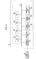
- Fig. 3 is a block diagram schematically illustrating the control unit 13.
- the controller (a block enclosed by a dashed line) disposed in the control unit 13 includes a CPU 201, a read only memory (ROM) 202, a random access memory (RAM) 203, a hard disk drive (HDD) 204, an image processing unit 207, an engine control unit 208, and an individual unit controller 209.
- the CPU 201 performs overall control of the printing apparatus.
- the ROM 202 stores programs executed by the CPU 201 and fixed data necessary for the printing apparatus to perform a variety of operations.
- the RAM 203 is used as a work area of the CPU 201 and a temporary storage area for a variety of received data items. In addition, the RAM 203 stores a variety of setting data items.
- the HDD 204 can store and deliver programs executed by the CPU 201, print data, and setting information necessary for the operation performed by the printing apparatus.
- the operation unit 15 serves as an input/output interface with the user.
- the operation unit 15 includes hard keys, an input unit of a touch-sensitive panel, and a display and a sound generator for outputting information.
- the image processing unit 207 performs image processing on print data manipulated by the printing apparatus.
- the image processing unit 207 converts the color space of the input image data (e.g., YCbCr) into a standard RGB color space (e.g., sRGB).
- the image processing unit 207 performs a variety of image processing, such as resolution conversion, image analysis, and image correction, on the image data as needed.
- Print data obtained through such image processing is stored in the RAM 203 or the HDD 204.
- the engine control unit 208 controls driving of the print head assembly 14 of the printing unit 4 using the print data.
- the engine control unit 208 further controls a conveying mechanism of each of the units in the printing apparatus.
- the individual unit controller 209 is a sub-controller that individually controls the sheet feeding unit 1, the decurl unit 2, the skew correction unit 3, the inspection unit 5, the cutter unit 6, the information recording unit 7, the drying unit 8, the reverse unit 9, the ejection conveying unit 10, the sorter unit 11, the ejection unit 12, and the humidifying unit 20.
- the individual unit controller 209 controls the operation of each of the units.
- An external interface 205 is an interface (I/F) used for connecting the controller to the host apparatus 16.
- the external interface 205 is a local I/F or a network I/F.
- the above-described components of the printing apparatus are connected to one another via a system bus 210.
- the host apparatus 16 serves as a supply source of image data to be printed by the printing apparatus.
- the host apparatus 16 may be a general-purpose computer or a dedicated computer.
- the host apparatus 16 may be a dedicated imaging device, such as an image capturing device including an image reader unit, a digital camera, or a photo storage device.
- OS operating system
- application software application software that generates image data
- printer driver for the printing apparatus installed therein.
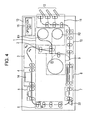
- Fig. 4 illustrates the operation performed in a simplex print mode.
- a sheet is fed from the sheet feeding unit 1 and is subjected to the processing performed by the decurl unit 2 and the skew correction unit 3. Thereafter, printing is performed on the front surface (the first surface) of the sheet in the printing unit 4.
- Printing of an image having a predetermined unit length in the conveying direction (a unit image) is sequentially performed on the continuous sheet.
- a plurality of images are formed to be sequentially arranged on the continuous sheet.
- the printed sheet passes through the inspection unit 5 and is cut into the unit images by the cutter unit 6.
- the print information is printed on the back surfaces of the cut sheets in the information recording unit 7 as needed.
- the cut sheets are conveyed to the drying unit 8 one by one, where the sheets are dried. Thereafter, the sheets pass through the ejection conveying unit 10 and are sequentially ejected and stacked on the ejection unit 12 of the sorter unit 11. In contrast, the sheet remaining on the side of the printing unit 4 after the last unit image is cut out is delivered back to the sheet feeding unit 1.
- the sheet is wound around the roll R1 or R2.
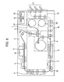
- Fig. 5 illustrates the operation performed in a duplex print mode.
- a duplex print mode after first print sequences on the front surface (the first surface) are completed, second print sequences on the back surface (the second surface) are performed.
- the operations performed by the sheet feeding unit 1 to the inspection unit 5 are the same as those in the simplex print mode.
- the cutting operation is not performed by the cutter unit 6.
- the continuous sheet is conveyed to the drying unit 8.
- the drying unit 8 dries the ink on the front surface of the continuous sheet. Thereafter, the sheet is led to the path on the side of the reverse unit 9 (the second path), not the path on the side of the ejection conveying unit 10 (the third path).
- the sheet is reeled in around the winding rotary member of the reverse unit 9 that rotates in the forward direction (the counterclockwise direction in Fig. 5 ).
- the trailing edge of the printed area of the continuous sheet is cut by the cutter unit 6.
- the entirety of the portion of the continuous sheet downstream of the cut position (on the side of the printed area) in the conveying direction is rewound by the reverse unit 9 via the drying unit 8.
- the portion of the continuous sheet remaining upstream of the cut position (on the side of the printing unit 4) in the conveying direction is fed back to the sheet feeding unit 1 and reeled in around the roll R1 or R2 so that the edge of the portion (the cut edge) does not remain in the decurl unit 2.
- the sheet does not collide with the sheet that is subsequently fed for the back surface printing described below.
- the winding rotary member of the reverse unit 9 rotates in a direction (a clockwise direction in Fig. 5 ) that is the reverse of the direction when the sheet was reeled in.
- the edge of the wound sheet (the trailing edge of the sheet when reeled is changed to the leading edge when fed) is conveyed into the decurl unit 2 along the path shown as a dashed line in Fig. 5 .
- a curl of the sheet given by the winding rotary member is decurled in the decurl unit 2.
- the decurl unit 2 is disposed between the sheet feeding unit 1 and the printing unit 4 in the first path and is disposed between the reverse unit 9 and the printing unit 4 in the second path.
- the decurl unit 2 serves as a shared unit for decurling.
- the turned-over sheet is advanced to the printing unit 4 via the skew correction unit 3, and printing on the back surface of the sheet is performed.
- the printed sheet passes through the inspection unit 5 and is cut into sheets each having a preset unit length by the cutter unit 6. Since either side of each of the cut sheets is printed, recording is not performed by the information recording unit 7.
- the cut sheets are conveyed to the drying unit 8 one by one. Thereafter, the cut sheets are sequentially ejected to the ejection unit 12 of the sorter unit 11 via the ejection conveying unit 10.
- the sheet passes through the first path, the second path, the first path, and the third path and is processed.
- the following sequences (1) to (11) are applied under the control of the control unit 13:
- Figs. 6A to 6D are schematic illustrations of the positional relationship among the units disposed along the sheet conveying path.
- Fig. 6A is a schematic illustration of the layout of the units of the printing apparatus according to the present embodiment.
- the first path extends from the sheet feeding unit 1 (S) to the drying unit 8 (H).
- the second path extends from the drying unit 8 to the printing unit 4 (P).
- the third path extends from the drying unit 8 to the ejection unit 12 (D).
- Figs. 6B to 6D are schematic illustrations of a virtual layout used for comparison with the present embodiment.
- the drying unit 8 (H) is disposed downstream of the cutter unit 6 (C).
- the sheet upstream of the cut position is rewound around the sheet feeding unit 1.
- the drying unit 8 is disposed upstream of the cutter unit 6, a portion of the sheet that has already passed through the drying unit 8 passes through the drying unit 8 again when the sheet after being cut is rewound around the sheet feeding unit 1. Accordingly, the leading edge portion of the sheet having a length equal to the path length between the drying unit 8 and the cutter unit 6 is partially and excessively dried.
- the information recording unit 7 (I) is disposed downstream of the cutter unit 6 (C) and upstream of the drying unit 8 (H). Since the sheet passes through the drying unit 8 immediately after being printed by the information recording unit 7, the ink applied by the information recording unit 7 rapidly dries. If, as indicated by the layouts shown in Figs. 6B and 6C , the information recording unit 7 is disposed downstream of the drying unit 8, the sheet is ejected onto the ejection unit 12 before the ink applied by the information recording unit 7 has dried. Thus, the ink may adhere to another stacked sheet.
- the reverse unit 9 (R) is disposed downstream of the drying unit 8 (H). Accordingly, in the duplex print mode, the ink applied to the front surface of the sheet is reliably dried in the drying unit 8 and, subsequently, the sheet is rewound by the reverse unit 9. If, as indicated by the layout shown in Fig. 6D , the reverse unit 9 is disposed upstream of the drying unit 8, the sheet is rewound before the ink applied by the printing unit 4 has dried. Thus, the ink may adhere to the topped sheet.
- the sheet passes through the shared drying unit 8 twice in the duplex print mode.
- the surface to which ink is applied in the first printing faces the floor when the sheet passes through the drying unit 8 twice.
- the ink is exposed to heated air generated by a heater and rising from below. That is, the drying unit 8 can be configured to heat mainly one side of the sheet, not both sides of the sheet. Therefore, the size of the drying unit 8 and the power consumption of the drying unit 8 can be reduced. As a result, the size of the printing apparatus and the power consumption of the printing apparatus can be reduced.
- the printing unit 4 (P) and the drying unit 8 (H) are arranged in the vertical direction on the same side of the sheet feeding unit 1 (S).
- the sheet is conveyed along a path having a substantially U-turn shape between the printing unit 4 and the drying unit 8.
- the direction in which the sheet moves in the printing unit 4 is opposite that in the drying unit 8.
- the printed sheet that has passed through the drying unit 8 passes through a path beneath the sheet feeding unit 1 and is ejected onto the ejection unit 12.
- Such a layout allows the sheet feeding unit 1 and the ejection unit 12 to be disposed in the vicinity of the end of the printing apparatus on the same side. Accordingly, the user can access the sheet feeding unit 1 and the ejection unit 12 without moving a long distance. Thus, the user can mount a new roll sheet and collect the printed sheets in an efficient manner.
- the printing unit 4 and the drying unit 8 are arranged in the vertical direction.
- the path between the printing unit 4 and the drying unit 8 has a substantially U-turn shape.
- an ejection path extending from the drying unit 8 is located beneath the sheet feeding unit 1. Since the units having a large size are arranged in the vertical direction, the footprint of the printing apparatus can be reduced.
- the printing unit 4 is disposed in the upper section of the housing of the printing apparatus. Accordingly, the user can easily maintain (e.g., exchange) the print head by inserting their hand from above.
- the gas having high temperature and humidity is not directly discharged from the drying unit 8 to the outside of the printing apparatus.
- the gas or heat is used for generating humidifying gas in the humidifying unit 20. Accordingly, the total energy efficiency of the printing apparatus can be increased.
- the sheet fed from the sheet feeding unit 1 to the printing unit 4 and the sheet fed from the reverse unit 9 to the printing unit 4 are decurled towards the appropriate direction by the shared decurl unit 2. That is, in the duplex print mode, two decurl operations can be performed before the front surface of the sheet is printed and before the back surface of the sheet is printed.
- the decurl unit 2 since the decurl unit 2 has a simplified and compact configuration, the overall size of the printing apparatus can be reduced.
- An apparatus for performing duplex printing having a sheet feeding unit (1), a printing unit (4), a cutter unit (6), a drying unit (8), and a reverse unit (9).
- the printing unit (4) prints images on a first surface of a continuous sheet fed from the sheet feeding unit (1).
- the sheet printed on the first surface passes through the drying unit (8) and is led to the reverse unit (9).
- the reverse unit (9) feeds the reversed sheet to the printing unit (4), which prints a plurality of images on a second surface that is a back of the first surface of the sheet fed from the reverse unit (9).
- the cutter unit (6) cuts the sheet printed on the second surface into a plurality of cut sheets each having the image printed thereon.
- the cut sheets pass through the drying unit (8) and are ejected.
Description
- The present invention relates to an apparatus and a method for performing printing on a sheet.
- Duplex printing is a printing apparatus feature that allows the automatic printing of a sheet on both sides. Japanese Patent Laid-Open No.
2008-126530 - When performing duplex printing, the apparatus described in Japanese Patent Laid-Open No.
2008-126530 2008-126530 2008-126530 - In a high volume printing market, such as print labs, it is required to increase the print throughput (the number of prints per unit time). One of the factors that prevents the print throughput from increasing is a long ink drying time after a print operation is performed. For the apparatus described in Japanese Patent Laid-Open No.
2008-126530 - The document
US 2004 046312 A1 can be regarded as the closest prior art and discloses an apparatus for performing duplex printing on a continuous sheet; the apparatus comprises a printing unit configured to perform ink-jet printing, a cutter unit, a dryer unit downstream of the cutter unit and a reverse unit configured to reverse the sheet that has passed through the drying unit. - Accordingly, the present invention provides a duplex printing apparatus having a high total print throughput by reducing an ink drying time. More specifically, the present invention provides a duplex printing apparatus including a plurality of units including a drying unit needed for high-speed duplex printing that are arranged in a rational manner. The present invention further provides a printing method and a sheet processing method for high-speed duplex printing.
- The present invention in its first aspect provides printing apparatus as specified in claims 1 to 16.
- The present invention in its second aspect provides a printing method as specified in claim 17.
- The present invention in its third aspect provides a sheet processing method as specified in claim 18.
- According to the present invention, in a duplex print mode, the ink drying time can be reduced and, therefore, a high-throughput printing apparatus and a high-throughput printing method can be realized.
- Further features of the present invention will become apparent from the following description of exemplary embodiments with reference to the attached drawings.
-
Fig. 1 is a schematic illustration of an exemplary internal configuration of a printing apparatus. -
Fig. 2 is a perspective view of an exemplary internal configuration of a drying unit. -
Fig. 3 is a block diagram schematically illustrating a control unit. -
Fig. 4 illustrates the operation performed in a simplex print mode. -
Fig. 5 illustrates the operation performed in a duplex print mode. -
Figs. 6A to 6D are schematic illustrations of the layouts of units of the printing apparatus along a sheet conveying path. - A printing apparatus using an inkjet printing method according to an embodiment of the present invention is described below. A unit of printing is referred to as a "page" or a "unit image" and a long continuous sheet is longer than repeated units of printing in the conveying direction of the sheet. According to the present embodiment, a printing apparatus employs a long continuous sheet. The printing apparatus is a high-speed line printer that is operable in either one of a simplex print mode and a duplex print mode. The printing apparatus is suitable for a high-volume printing market, such as print labs. As used herein, even when a plurality of small images, characters, and blanks are present in an area of a unit of printing (a page), the small images, characters, and blanks are collectively referred to as a "unit image". That is, the term "unit image" refers to a unit of printing (a page) when a plurality of pages are sequentially printed on continuous sheet. Note that a unit image is also simply referred to as an "image". The length of a unit image varies in accordance with the image size to be printed. For example, the length of an L size photo in the conveying direction is 135 mm, and the length of an A4 size photo in the conveying direction is 297 mm.
- The present invention is widely applicable to a printing apparatus that uses ink and requires an ink drying process, such as a printer, a multi function peripheral, a copier, a facsimile, or equipment used for manufacturing a variety of devices. In addition, the present invention is applicable to a printing apparatus that renders a latent image using, for example, a laser beam and performs printing using a liquid development method.
-
Fig. 1 is a cross-sectional view schematically illustrating the internal configuration of the printing apparatus. According to the present embodiment, the printing apparatus can perform duplex printing on the first surface of a rolled sheet, which is a front surface of the first sheet, and the second surface of the sheet, which is a back surface of the first sheet. The printing apparatus includes a sheet feeding unit 1, adecurl unit 2, a skew correction unit 3, aprinting unit 4, aninspection unit 5, acutter unit 6, aninformation recording unit 7, adrying unit 8, areverse unit 9, anejection conveying unit 10, asorter unit 11, anejection unit 12, ahumidifying unit 20, and acontrol unit 13. A sheet is conveyed by a conveying mechanism including rollers or a belt disposed along a sheet conveying path shown as a solid line inFig. 1 and is processed by the units. The sheet is conveyed downstream along the sheet conveyance path while printing. At an arbitrary position in the sheet conveyance path where the sheet is conveyed from feeding means to discharging means, a side toward the feeding means is referred to as "the upstream side", and the opposite side toward the discharging means is referred to as "the downstream side". - The sheet feeding unit 1 holds a rolled continuous sheet and feeds the continuous sheet. The sheet feeding unit 1 can contain two rolls R1 and R2. The sheet feeding unit 1 selects one of the rolls R1 and R2 and draws a sheet from the selected roll and feeds the sheet. Note that the number of rolls contained in the sheet feeding unit 1 is not limited to two. For example, the number of contained rolls may be one or three or more. Alternatively, a continuous sheet that is not rolled can be used. For example, a continuous sheet having perforations at predetermined intervals may be folded at the perforations and stacked in the sheet feeding unit 1.
- The
decurl unit 2 reduces the curl of the sheet fed from the sheet feeding unit 1. Thedecurl unit 2 allows the sheet to pass therethrough using two pinch rollers corresponding to one driving rollers in order to curve the sheet so that an inverse curl is supplied to the sheet. In this way, a decurling force is applied to the sheet and, therefore, the curl is reduced. - The skew correction unit 3 corrects the skew of the sheet that has passed through the decurl unit 2 (the inclination of the sheet with respect to the designed feed direction). By urging the end of the sheet on the reference side against a guide member, a skew can be corrected.
- The
printing unit 4 performs a printing operation on the sheet and forms an image on the sheet using aprint head assembly 14 disposed above the conveyed sheet. That is, theprinting unit 4 serves as a processing unit that performs a predetermined processing on the sheet. Theprinting unit 4 includes a plurality of conveying rollers that convey the sheet. Theprint head assembly 14 includes a line print head having an inkjet nozzle row that covers the maximum width of the sheet to be used. In theprint head assembly 14, a plurality of print heads are arranged in parallel along the conveying direction. In this example, theprint head assembly 14 includes seven print heads corresponding to the following seven colors: cyan (C), magenta (M), yellow (Y), light cyan (LC), light magenta (LM), grey (G), and black (K). However, it should be noted that the number of colors and the number of print heads are not limited to seven. Examples of the inkjet method include a method using a heater element, a method using a piezoelectric element, a method using an electrostatic element, and a method using a microelectromechanical system (MEMS) element. The ink of each color is supplied from an ink tank to theprint head assembly 14 via an ink tube. - The
inspection unit 5 optically scans, using a scanner, an inspection pattern or an image printed on a sheet by theprinting unit 4 and inspects the state of a nozzle of the print head, the conveying state of a sheet, and the position of an image. In this way, theinspection unit 5 determines whether an image has been correctly printed. The scanner includes a charge-coupled device (CCD) image sensor or a complementary metal-oxide semiconductor (CMOS) image sensor. - The
cutter unit 6 includes a mechanical cutter that cuts the printed sheet into predetermined lengths. Thecutter unit 6 further includes a plurality of conveying rollers that convey the sheet to the next processing stage. - The
information recording unit 7 records print information (unique information), such as the serial number of the printout and the date and time, in the non-print area of the cut sheet. The information is recorded by printing characters and code on the sheet using, for example, an inkjet method or a thermal transfer method. Asensor 23 is disposed upstream of theinformation recording unit 7 and downstream of thecutter unit 6. That is, thesensor 23 detects the edge of the sheet at a recording position located between thecutter unit 6 and theinformation recording unit 7. Theinformation recording unit 7 controls a point in time at which the information is recorded on the basis of a point in time at which thesensor 23 detects the edge of the sheet. - The drying
unit 8 heats the sheet printed by theprinting unit 4 to dry the applied ink in a short time. The dryingunit 8 includes conveyer belts and conveying rollers for advancing the sheet to the next processing stage.Fig. 2 illustrates an exemplary internal configuration of thedrying unit 8. The sheet is pinched by a plurality ofconveyer belts 31 androllers 32 and is moved. A rotational driving force generated by amotor 35 is transferred to the plurality ofconveyer belts 31. The rotation state of themotor 35 is detected by arotary encoder 36. Thus, the rotation state of therotary encoder 36 provides feedback information such that themotor 35 is feedback-controlled. A printed surface having the ink thereon that should be dried faces downward (towards the floor). Gas (the air) heated by aheater 34 is circulated by a fan 33 in the Z direction inFig. 2 . Thus, the heated air is applied to the sheet that passes through the dryingunit 8 in at least the upward direction. In this way, the surface having the ink applied thereon is dried. If the ink is rapidly dried, the sheet is easily warped. However, during a drying operation, the sheet is pinched by the plurality ofconveyer belts 31 and the plurality ofconveyer belts 31 androllers 32. Accordingly, the warping of the sheet is prevented. Note that instead of applying heated air, the dryingunit 8 can dry the ink by radiating electromagnetic waves (e.g., ultraviolet rays or infrared rays) to the surface of the sheet. - As used herein, the above-described sheet conveying path from the sheet feeding unit 1 to the
drying unit 8 is referred to as a "first path". The first path has a shape to perform a U-turn between theprinting unit 4 and thedrying unit 8. Thecutter unit 6 is located in the U-turn. - The
reverse unit 9 temporarily winds the printed continuous sheet and turns over the sheet when duplex printing is performed. In order to feed the sheet that has passed through the dryingunit 8 to theprinting unit 4 again, thereverse unit 9 is disposed in a path from the dryingunit 8 to theprinting unit 4 via the decurl unit 2 (a loop path, hereinafter referred to as a "second path"). Thereverse unit 9 includes a winding rotary member (a drum) that rotates to reel in the sheet. The printed continuous sheet before being cut is temporarily wound around the winding rotary member. After the continuous sheet is wound, the winding rotary member rotates in the opposite direction and, therefore, the continuous sheet is fed in a direction opposite that when the continuous sheet is wound. The continuous sheet is fed to thedecurl unit 2 and is delivered to theprinting unit 4. Since the sheet is turned over, theprinting unit 4 can perform a printing operation on the back surface of the sheet. Such duplex printing is described in more detail below. - The
ejection conveying unit 10 conveys the sheet cut by thecutter unit 6 and dried by the dryingunit 8 and delivers the sheet to thesorter unit 11. Theejection conveying unit 10 is disposed in a path that is different from the second path having thereverse unit 9 thereon (hereinafter, referred to as a "third path"). In order to selectively deliver the sheet that has been conveyed along the first path to the second path or the third path, a path switching mechanism including a movable flapper is disposed at a branch position in the path. - The
sorter unit 11 and theejection unit 12 are disposed at the end of the third path to be adjacent to the sheet feeding unit 1. Thesorter unit 11 sorts the printed sheets into groups as needed. The sorted sheets are ejected to theejection unit 12 including a plurality of trays. In this way, the third path is designed to allow a sheet to pass beneath the sheet feeding unit 1 and allow the sheet to be ejected to the opposite side of the sheet feeding unit 1 from theprinting unit 4 and thedrying unit 8. - As described above, the units from the sheet feeding unit 1 to the
drying unit 8 are sequentially arranged along the first path. Downstream of thedrying unit 8, the first path branches into the second path and the third path. Thereverse unit 9 is disposed in the middle of the second path. Downstream of thereverse unit 9, the second path merges with the first path. Theejection unit 12 is disposed at the end of the third path. - The
humidifying unit 20 generates humidifying gas (the humidifying air) and supplies the generated humidifying gas to a space between theprint head assembly 14 of theprinting unit 4 and the sheet. Thus, drying of the ink in nozzles of theprint head assembly 14 can be prevented. Examples of the humidifying method employed by thehumidifying unit 20 include a vaporization method, a water spray method, and a steam air method. In addition to a rotary method according to the present embodiment, the vaporization method has a water permeable membrane type, a water droplet infiltration type, and a capillary type. The water spray method has an ultrasonic type, a centrifugal impeller type, a high-pressure spray type, and a two-liquid spray type. The steam air method has a steam piping type, an electrical heating type, and an electrode type. Thehumidifying unit 20 is connected to theprinting unit 4 using afirst duct 21. Furthermore, thehumidifying unit 20 is connected to thedrying unit 8 using asecond duct 22. In thedrying unit 8, humid and high-temperature gas is generated when the sheet is dried. The gas is led to thehumidifying unit 20 via thesecond duct 22 and is used as auxiliary energy for generating humidifying gas in thehumidifying unit 20. The humidifying gas generated in thehumidifying unit 20 is led to theprinting unit 4 via thefirst duct 21. - The
control unit 13 performs overall control of the printing apparatus. Thecontrol unit 13 includes a controller having a central processing unit (CPU), a storage unit, and a variety of control sub-units, an external interface, and anoperation unit 15 used by the user when the user inputs data and receives output data. The operation performed by the printing apparatus is controlled using instructions received from the controller or ahost apparatus 16, such as a host computer, connected to the controller via the external interface. -
Fig. 3 is a block diagram schematically illustrating thecontrol unit 13. The controller (a block enclosed by a dashed line) disposed in thecontrol unit 13 includes aCPU 201, a read only memory (ROM) 202, a random access memory (RAM) 203, a hard disk drive (HDD) 204, animage processing unit 207, anengine control unit 208, and anindividual unit controller 209. TheCPU 201 performs overall control of the printing apparatus. The ROM 202 stores programs executed by theCPU 201 and fixed data necessary for the printing apparatus to perform a variety of operations. TheRAM 203 is used as a work area of theCPU 201 and a temporary storage area for a variety of received data items. In addition, theRAM 203 stores a variety of setting data items. TheHDD 204 can store and deliver programs executed by theCPU 201, print data, and setting information necessary for the operation performed by the printing apparatus. Theoperation unit 15 serves as an input/output interface with the user. Theoperation unit 15 includes hard keys, an input unit of a touch-sensitive panel, and a display and a sound generator for outputting information. - Each of the units that are required to perform a high-speed operation includes a dedicated processing unit. The
image processing unit 207 performs image processing on print data manipulated by the printing apparatus. Theimage processing unit 207 converts the color space of the input image data (e.g., YCbCr) into a standard RGB color space (e.g., sRGB). In addition, theimage processing unit 207 performs a variety of image processing, such as resolution conversion, image analysis, and image correction, on the image data as needed. Print data obtained through such image processing is stored in theRAM 203 or theHDD 204. In response to a control command received from theCPU 201, theengine control unit 208 controls driving of theprint head assembly 14 of theprinting unit 4 using the print data. Theengine control unit 208 further controls a conveying mechanism of each of the units in the printing apparatus.
Theindividual unit controller 209 is a sub-controller that individually controls the sheet feeding unit 1, thedecurl unit 2, the skew correction unit 3, theinspection unit 5, thecutter unit 6, theinformation recording unit 7, the dryingunit 8, thereverse unit 9, theejection conveying unit 10, thesorter unit 11, theejection unit 12, and thehumidifying unit 20. In response to an instruction received from theCPU 201, theindividual unit controller 209 controls the operation of each of the units. Anexternal interface 205 is an interface (I/F) used for connecting the controller to thehost apparatus 16. Theexternal interface 205 is a local I/F or a network I/F. The above-described components of the printing apparatus are connected to one another via asystem bus 210. - The
host apparatus 16 serves as a supply source of image data to be printed by the printing apparatus. Thehost apparatus 16 may be a general-purpose computer or a dedicated computer. Alternatively, thehost apparatus 16 may be a dedicated imaging device, such as an image capturing device including an image reader unit, a digital camera, or a photo storage device. When thehost apparatus 16 is a computer, a storage unit of the computer stores an operating system (OS), application software that generates image data, and a printer driver for the printing apparatus installed therein. However, it should be noted that all of the above-described processes are not necessarily realized by software. Some or all of the processes may be realized by hardware. - The basic operation performed during a printing operation is described next. The operation in a simplex print mode differs from that in a duplex print mode. Accordingly, both the operations are described below.
-
Fig. 4 illustrates the operation performed in a simplex print mode. A sheet is fed from the sheet feeding unit 1 and is subjected to the processing performed by thedecurl unit 2 and the skew correction unit 3. Thereafter, printing is performed on the front surface (the first surface) of the sheet in theprinting unit 4. Printing of an image having a predetermined unit length in the conveying direction (a unit image) is sequentially performed on the continuous sheet. Thus, a plurality of images are formed to be sequentially arranged on the continuous sheet. The printed sheet passes through theinspection unit 5 and is cut into the unit images by thecutter unit 6. The print information is printed on the back surfaces of the cut sheets in theinformation recording unit 7 as needed. Subsequently, the cut sheets are conveyed to thedrying unit 8 one by one, where the sheets are dried. Thereafter, the sheets pass through theejection conveying unit 10 and are sequentially ejected and stacked on theejection unit 12 of thesorter unit 11. In contrast, the sheet remaining on the side of theprinting unit 4 after the last unit image is cut out is delivered back to the sheet feeding unit 1. The sheet is wound around the roll R1 or R2. - In this way, in a simplex print mode, the sheet passes through the first path and the third path. The sheet does not pass through the second path. In summary, in a simplex print mode, the following six sequences (1) to (6) are applied under the control of the control unit 13:
- (1) feeding a sheet from the sheet feeding unit 1 and feeding the sheet to the
printing unit 4, - (2) repeating printing of a unit image on the first surface of the fed sheet in the
printing unit 4, - (3) repeating a cutting operation of the sheet for each of the unit images printed on the first surface of the sheet,
- (4) allowing the cut sheets each having a unit image thereon to pass through the drying
unit 8 one by one and facilitating drying of the ink, - (5) ejecting the sheets that have passed through the drying
unit 8 one by one onto theejection unit 12 via the third path, and - (6) cutting the sheet for the last unit image and delivering back the sheet remaining on the side of the
printing unit 4 to the sheet feeding unit 1. -
Fig. 5 illustrates the operation performed in a duplex print mode. In a duplex print mode, after first print sequences on the front surface (the first surface) are completed, second print sequences on the back surface (the second surface) are performed. In the first print sequences, the operations performed by the sheet feeding unit 1 to theinspection unit 5 are the same as those in the simplex print mode. However, the cutting operation is not performed by thecutter unit 6. The continuous sheet is conveyed to thedrying unit 8. The dryingunit 8 dries the ink on the front surface of the continuous sheet. Thereafter, the sheet is led to the path on the side of the reverse unit 9 (the second path), not the path on the side of the ejection conveying unit 10 (the third path). In the second path, the sheet is reeled in around the winding rotary member of thereverse unit 9 that rotates in the forward direction (the counterclockwise direction inFig. 5 ). After the printing on planned area of the front surface is completed in theprinting unit 4, the trailing edge of the printed area of the continuous sheet is cut by thecutter unit 6. The entirety of the portion of the continuous sheet downstream of the cut position (on the side of the printed area) in the conveying direction is rewound by thereverse unit 9 via thedrying unit 8. In contrast, at the same time as the rewinding operation, the portion of the continuous sheet remaining upstream of the cut position (on the side of the printing unit 4) in the conveying direction is fed back to the sheet feeding unit 1 and reeled in around the roll R1 or R2 so that the edge of the portion (the cut edge) does not remain in thedecurl unit 2. Through such rewinding operation, the sheet does not collide with the sheet that is subsequently fed for the back surface printing described below. - After the above-described front surface printing sequences are completed, the processing is switched to the back surface printing sequences. The winding rotary member of the
reverse unit 9 rotates in a direction (a clockwise direction inFig. 5 ) that is the reverse of the direction when the sheet was reeled in. The edge of the wound sheet (the trailing edge of the sheet when reeled is changed to the leading edge when fed) is conveyed into thedecurl unit 2 along the path shown as a dashed line inFig. 5 . A curl of the sheet given by the winding rotary member is decurled in thedecurl unit 2. That is, thedecurl unit 2 is disposed between the sheet feeding unit 1 and theprinting unit 4 in the first path and is disposed between thereverse unit 9 and theprinting unit 4 in the second path. In either path, thedecurl unit 2 serves as a shared unit for decurling. The turned-over sheet is advanced to theprinting unit 4 via the skew correction unit 3, and printing on the back surface of the sheet is performed. The printed sheet passes through theinspection unit 5 and is cut into sheets each having a preset unit length by thecutter unit 6. Since either side of each of the cut sheets is printed, recording is not performed by theinformation recording unit 7. The cut sheets are conveyed to thedrying unit 8 one by one. Thereafter, the cut sheets are sequentially ejected to theejection unit 12 of thesorter unit 11 via theejection conveying unit 10. - In this way, in the duplex print mode, the sheet passes through the first path, the second path, the first path, and the third path and is processed. In summary, in the duplex print mode, the following sequences (1) to (11) are applied under the control of the control unit 13:
- (1) feeding a sheet from the sheet feeding unit 1 and feeding the sheet to the
printing unit 4, - (2) repeating printing of a unit image on the first surface of the fed sheet using the
printing unit 4, - (3) allowing the sheet having the printed first surface to pass through the drying
unit 8 to facilitate drying, - (4) leading the sheet that has passed through the drying
unit 8 to the second path and winding the sheet around the winding rotary member of thereverse unit 9, - (5) cutting the sheet at the tail end of the last printed unit image using the
cutter unit 6 after repeated printing on the first surface is completed, - (6) winding the cut sheet around the winding rotary member until the trailing edge of the cut sheet passes through the drying
unit 8 and reaches the winding rotary member and, concurrently, conveying the sheet remaining on the side of theprinting unit 4 after cutting back to the sheet feeding unit 1, - (7) rotating the winding rotary member in the opposite direction after the winding is completed and feeding the sheet to the
printing unit 4 via the second path again, - (8) repeatedly printing a unit image on the second surface of the sheet fed from the second path using the
printing unit 4, - (9) cutting the sheet for each of the unit images printed on the second surface using the
cutter unit 6, - (10) allowing the cut sheets each having a unit image thereon to pass through the drying
unit 8 one by one in order to facilitate drying the ink, and - (11) ejecting each of the cut sheets that has passed through the drying
unit 8 onto theejection unit 12 via the third path. - The rationality of the above-described layout of the units of the printing apparatus in the vicinity of the
drying unit 8 is described in more detail below.Figs. 6A to 6D are schematic illustrations of the positional relationship among the units disposed along the sheet conveying path.Fig. 6A is a schematic illustration of the layout of the units of the printing apparatus according to the present embodiment. InFig. 6A , the first path extends from the sheet feeding unit 1 (S) to the drying unit 8 (H). The second path extends from the dryingunit 8 to the printing unit 4 (P). The third path extends from the dryingunit 8 to the ejection unit 12 (D).Figs. 6B to 6D are schematic illustrations of a virtual layout used for comparison with the present embodiment. - In the layout shown in
Fig. 6A according to the present embodiment, the drying unit 8 (H) is disposed downstream of the cutter unit 6 (C). As described above, in a duplex print mode, after the front surface is printed and the sheet is cut into cut sheets, the sheet upstream of the cut position is rewound around the sheet feeding unit 1. If, as indicated by the layout shown inFig. 6B , the dryingunit 8 is disposed upstream of thecutter unit 6, a portion of the sheet that has already passed through the dryingunit 8 passes through the dryingunit 8 again when the sheet after being cut is rewound around the sheet feeding unit 1. Accordingly, the leading edge portion of the sheet having a length equal to the path length between the dryingunit 8 and thecutter unit 6 is partially and excessively dried. Thus, non-uniform moistening occurs. However, according to the layout shown inFig. 6A , since the sheet is cut at a position upstream of thedrying unit 8, non-uniform moistening of the sheet does not occur even when the sheet is rewound. - In the layout shown in
Fig. 6A according to the present embodiment, the information recording unit 7 (I) is disposed downstream of the cutter unit 6 (C) and upstream of the drying unit 8 (H). Since the sheet passes through the dryingunit 8 immediately after being printed by theinformation recording unit 7, the ink applied by theinformation recording unit 7 rapidly dries. If, as indicated by the layouts shown inFigs. 6B and 6C , theinformation recording unit 7 is disposed downstream of thedrying unit 8, the sheet is ejected onto theejection unit 12 before the ink applied by theinformation recording unit 7 has dried. Thus, the ink may adhere to another stacked sheet. - In the layout shown in
Fig. 6A according to the present embodiment, the reverse unit 9 (R) is disposed downstream of the drying unit 8 (H). Accordingly, in the duplex print mode, the ink applied to the front surface of the sheet is reliably dried in thedrying unit 8 and, subsequently, the sheet is rewound by thereverse unit 9. If, as indicated by the layout shown inFig. 6D , thereverse unit 9 is disposed upstream of thedrying unit 8, the sheet is rewound before the ink applied by theprinting unit 4 has dried. Thus, the ink may adhere to the topped sheet. - In the layout shown in
Fig. 6A according to the present embodiment, the sheet passes through the shareddrying unit 8 twice in the duplex print mode. The surface to which ink is applied in the first printing faces the floor when the sheet passes through the dryingunit 8 twice. Thus, the ink is exposed to heated air generated by a heater and rising from below. That is, the dryingunit 8 can be configured to heat mainly one side of the sheet, not both sides of the sheet. Therefore, the size of thedrying unit 8 and the power consumption of thedrying unit 8 can be reduced. As a result, the size of the printing apparatus and the power consumption of the printing apparatus can be reduced. - In the layout shown in
Fig. 6A according to the present embodiment, the printing unit 4 (P) and the drying unit 8 (H) are arranged in the vertical direction on the same side of the sheet feeding unit 1 (S). The sheet is conveyed along a path having a substantially U-turn shape between theprinting unit 4 and thedrying unit 8. The direction in which the sheet moves in theprinting unit 4 is opposite that in thedrying unit 8. The printed sheet that has passed through the dryingunit 8 passes through a path beneath the sheet feeding unit 1 and is ejected onto theejection unit 12. Such a layout allows the sheet feeding unit 1 and theejection unit 12 to be disposed in the vicinity of the end of the printing apparatus on the same side. Accordingly, the user can access the sheet feeding unit 1 and theejection unit 12 without moving a long distance. Thus, the user can mount a new roll sheet and collect the printed sheets in an efficient manner. - The
printing unit 4 and thedrying unit 8 are arranged in the vertical direction. The path between theprinting unit 4 and thedrying unit 8 has a substantially U-turn shape. In addition, an ejection path extending from the dryingunit 8 is located beneath the sheet feeding unit 1. Since the units having a large size are arranged in the vertical direction, the footprint of the printing apparatus can be reduced. - In the layout shown in
Fig. 6A according to the present embodiment, theprinting unit 4 is disposed in the upper section of the housing of the printing apparatus. Accordingly, the user can easily maintain (e.g., exchange) the print head by inserting their hand from above. - According to the present embodiment, the gas having high temperature and humidity is not directly discharged from the drying
unit 8 to the outside of the printing apparatus. The gas or heat is used for generating humidifying gas in thehumidifying unit 20. Accordingly, the total energy efficiency of the printing apparatus can be increased. - According to the present embodiment, the sheet fed from the sheet feeding unit 1 to the
printing unit 4 and the sheet fed from thereverse unit 9 to theprinting unit 4 are decurled towards the appropriate direction by the shareddecurl unit 2. That is, in the duplex print mode, two decurl operations can be performed before the front surface of the sheet is printed and before the back surface of the sheet is printed. In addition, since thedecurl unit 2 has a simplified and compact configuration, the overall size of the printing apparatus can be reduced. - While the present invention has been described with reference to exemplary embodiments, it is to be understood that the invention is not limited to the disclosed exemplary embodiments. An apparatus for performing duplex printing having a sheet feeding unit (1), a printing unit (4), a cutter unit (6), a drying unit (8), and a reverse unit (9). In duplex printing, the printing unit (4) prints images on a first surface of a continuous sheet fed from the sheet feeding unit (1). The sheet printed on the first surface passes through the drying unit (8) and is led to the reverse unit (9). The reverse unit (9) feeds the reversed sheet to the printing unit (4), which prints a plurality of images on a second surface that is a back of the first surface of the sheet fed from the reverse unit (9). The cutter unit (6) cuts the sheet printed on the second surface into a plurality of cut sheets each having the image printed thereon. The cut sheets pass through the drying unit (8) and are ejected.
Claims (15)
- An apparatus for performing duplex printing comprising:a sheet feeding unit (1) configured to feed a sheet along a path, wherein the sheet is continuous;a printing unit (4), disposed in the path, configured to perform inkjet printing on the sheet;a cutter unit (6), disposed downstream of the printing unit (4) in the path, configured to cut the sheet;a drying unit (8), disposed downstream of the cutter unit (6) in the path, configured to dry the sheet printed in the printing unit (4); anda reverse unit (9) configured to reverse the sheet that has passed through the drying unit (8),wherein, for performing the duplex printing, the printing unit (4) is configured to print a plurality of images on a first surface of the sheet fed from the sheet feeding unit (1), the apparatus being configured to pass the sheet printed on the first surface through the drying unit (8) and lead it to the reverse unit (9), the reverse unit (9) is configured to feed the reversed sheet to the printing unit (4), the printing unit (4) is configured to print a plurality of images on a second surface that is a back of the first surface of the sheet fed from the reverse unit (9), the cutter unit (6) is configured to cut the sheet printed on the second surface into a plurality of cut sheets, and the apparatus being configured to pass the cut sheets through the drying unit (8) and eject them.
- The apparatus according to Claim 1, wherein the cutter unit (6) is configured to cut the sheet after printing of the plurality of images on the first surface is completed, and the apparatus being configured to convey the sheet remaining on a side of the printing unit (4) back to the sheet feeding unit (1) before the reverse unit (9) feeds the sheet to the printing unit (4) again.
- The apparatus according to Claim 1, wherein the reverse unit (9) includes a winding rotary member, and in the duplex printing, the apparatus being configured to reel the sheet having a plurality of images printed on the first surface in the winding rotary member, subsequently, to rotate the winding rotary member in an opposite direction, and to feed the reeled sheet to the printing unit again.
- The apparatus according to Claim 3, wherein sheet feeding unit (1), the printing unit (4), the cutter unit (6), and the drying unit (8) are arranged along a first path, the first path branches into a second path and a third path, the reverse unit (9) is disposed in the second path and the second path merges with the first path at an upstream side of the printing unit (4), and an ejection unit (12) to which the cut sheets are ejected is disposed at the third path.
- The apparatus according to Claim 3, wherein the apparatus is configured to apply in the duplex printing, the following sequences:(1) feeding the continuous sheet from the sheet feeding unit (1) to the printing unit (4),(2) printing the plurality of images sequentially on the first surface of the sheet fed from the sheet feeding unit (1) using the printing unit (4),(3) allowing the sheet printed on the first surface to pass through the drying unit (8),(4) cutting the sheet, into a cut sheet, at a tail end of a last printed image using the cutter unit (6) after printing on the first surface is completed,(5) winding the cut sheet around the winding rotary member until a trailing edge of the cut sheet passes through the drying unit (8) and reaches the winding rotary member and, concurrently, conveying the sheet remaining on the side of the printing unit (4) back to the sheet feeding unit (1),(6) rotating the winding rotary member in the opposite direction after the winding is completed and feeding the reversed sheet to the printing unit (4) again,(7) printing the plurality of images sequentially on the second surface of the sheet fed from the winding rotary member using the printing unit (4),(8) cutting the sheet printed on the second surface using the cutter unit (6) into the plurality of cut sheets each having the image printed thereon, and(9) allowing the cut sheets to pass through the drying unit (8) one by one, and ejecting each of the cut sheets.
- The apparatus according to Claim 5, wherein at least one of the duplex printing and a simplex printing is selectable, and wherein the apparatus is configured to apply in the simplex printing, the following sequences:(1) feeding the continuous sheet from the sheet feeding unit (1) to the printing unit (4),(2) printing the plurality of images sequentially on the first surface of the sheet fed from the sheet feeding unit (1) using the printing unit (4),(3) cutting the sheet printed on the first surface using the cutter unit (6) into a plurality of cut sheets each having the image printed thereon, and(4) allowing the cut sheets to pass through the drying unit (8) one by one, and ejecting each of the cut sheets.
- The apparatus according to Claim 1, wherein the printing unit includes a print head (14) that applies, from above, ink to the sheet passing through the printing unit (4), and wherein the printing unit (4) is located above the drying unit (8), and wherein a direction in which the sheet moves in the printing unit (4) is opposite to a direction in which the sheet moves in the drying unit (8).
- The apparatus according to Claim 7 comprising one of the following alternatives a) to c):a) a path between the printing unit (4) and the drying unit (8) has a U-turn shape, and the cutter unit (6) is disposed in the path of the U-turn shape;b) part of a path in which the cut sheets are ejected extends beneath the sheet feeding unit (1), and the cut sheets are ejected to an ejection unit (12) disposed adjacent to the sheet feeding unit (1);c) the drying unit (8) includes a mechanism that applies heated air to the sheet passing through the drying unit (8) at least from below so that the surface of the sheet having ink applied thereon is dried.
- The apparatus according to Claim 1, further comprising:an information recording unit (7) configured to record unique information on each of cut sheets cut by the cutter unit (6);wherein the information recording unit (7) is configured to record the information at a recording position between the cutter unit (6) and the drying unit (8).
- The apparatus according to Claim 9, further comprising:a sensor (23) configured to detect an end of each of the cut sheets between the cutter unit (6) and the recording position,wherein a recording timing of the information recording unit (7) is controlled on a basis of detection of the sensor (23).
- The apparatus according to Claim 1, further comprising:a humidifying unit (20) configured to generate humidifying gas;wherein gas or heat discharged from the drying unit (8) is used to generate the humidifying gas by the humidifying unit.
- The apparatus according to Claim 11, further comprising:a first duct (21) configured to introduce the humidifying gas from the humidifying unit (20) to the printing unit (4); anda second duct (22) configured to introduce gas discharged from the drying unit (8) to the humidifying unit (20);wherein the gas discharged from the drying unit (8) is used to generate the humidifying gas by the humidifying unit (20).
- The apparatus according to Claim 1, further comprising:a decurl unit (2) configured to reduce a curl of the sheet fed from the sheet feeding unit (1) to the printing unit (4), and a curl of the sheet fed from the reverse unit (9) to the printing unit (4).
- The apparatus according to Claim 13, further comprising:a skew correction unit (3) configured to correct a skew of the sheet between the decurl unit (2) and the printing unit (4).
- A method, comprising:(1) feeding a sheet from a sheet feeding unit (1) to a printing unit (4), wherein the sheet is continuous;(2) printing a plurality of images sequentially on a first surface of the sheet fed from the sheet feeding unit (1) using the printing unit (4);(3) allowing the sheet printed on the first surface to pass through a heating unit;(4) cutting the sheet, into a cut sheet, at a tail end of a last printed image using a cutter unit (6) after printing on the first surface is completed;(5) winding the cut sheet around a winding rotary member until a trailing edge of the cut sheet passes through the heating unit and reaches the winding rotary member;(6) rotating the winding rotary member in an opposite direction after the winding is completed and feeding the sheet to the printing unit (4) again;(8) printing a plurality of images on a second surface that is a back of the first surface of the sheet fed from the winding rotary member using the printing unit (4);(9) cutting the sheet printed on the second surface into the plurality of cut sheets each having the image printed thereon using the cutter unit (6); and(10) allowing the cut sheets to pass through the heating unit one by one.
Applications Claiming Priority (1)
| Application Number | Priority Date | Filing Date | Title |
|---|---|---|---|
| JP2010042349A JP5361765B2 (en) | 2010-02-26 | 2010-02-26 | Printing apparatus, printing method, and sheet processing method |
Publications (2)
| Publication Number | Publication Date |
|---|---|
| EP2363293A1 EP2363293A1 (en) | 2011-09-07 |
| EP2363293B1 true EP2363293B1 (en) | 2015-12-23 |
Family
ID=44025204
Family Applications (1)
| Application Number | Title | Priority Date | Filing Date |
|---|---|---|---|
| EP11155806.0A Active EP2363293B1 (en) | 2010-02-26 | 2011-02-24 | Printing apparatus, printing method, and sheet processing method |
Country Status (4)
| Country | Link |
|---|---|
| US (1) | US8540360B2 (en) |
| EP (1) | EP2363293B1 (en) |
| JP (1) | JP5361765B2 (en) |
| CN (1) | CN102189778B (en) |
Cited By (1)
| Publication number | Priority date | Publication date | Assignee | Title |
|---|---|---|---|---|
| US11415914B2 (en) * | 2020-06-09 | 2022-08-16 | Canon Kabushiki Kaisha | Image recording apparatus |
Families Citing this family (10)
| Publication number | Priority date | Publication date | Assignee | Title |
|---|---|---|---|---|
| JP5921139B2 (en) * | 2011-10-21 | 2016-05-24 | キヤノン株式会社 | Printing device |
| BR112014010373B1 (en) * | 2011-10-31 | 2020-07-07 | Hewlett-Packard Development Company, L.P. | pen printing apparatus, printing device and method of covering a printer printing pen |
| US8913095B2 (en) * | 2012-06-26 | 2014-12-16 | Kodak Alaris Inc. | Duplex thermal printer with pivotable diverter |
| JP5734323B2 (en) * | 2013-01-09 | 2015-06-17 | シャープ株式会社 | Printing device |
| JP2014166908A (en) * | 2013-02-28 | 2014-09-11 | Toshiba Tec Corp | Printer |
| JP6393138B2 (en) * | 2014-09-26 | 2018-09-19 | 株式会社Screenホールディングス | Inkjet printing apparatus and skew correction method thereof |
| JP2016078250A (en) * | 2014-10-10 | 2016-05-16 | キヤノン株式会社 | Printer and print method |
| JP6397319B2 (en) * | 2014-11-27 | 2018-09-26 | 理想科学工業株式会社 | Printing device |
| JP7003440B2 (en) * | 2016-07-13 | 2022-01-20 | セイコーエプソン株式会社 | Intermediate unit, post-processing equipment, and printing equipment |
| JP7298362B2 (en) * | 2019-07-24 | 2023-06-27 | ブラザー工業株式会社 | IMAGE FORMING SYSTEM AND IMAGE FORMING SYSTEM CONTROL METHOD |
Family Cites Families (40)
| Publication number | Priority date | Publication date | Assignee | Title |
|---|---|---|---|---|
| US4453841A (en) * | 1982-03-08 | 1984-06-12 | The Mead Corporation | Duplex printing system and method therefor |
| JPS6128754U (en) * | 1984-07-24 | 1986-02-20 | 富士ゼロックス株式会社 | Paper decurling device |
| CN1122751A (en) | 1994-09-28 | 1996-05-22 | 科-帕克株式会社 | Apparatus for printing characters onto both surfaces of a sheet materials |
| US5987300A (en) | 1997-04-10 | 1999-11-16 | Ricoh Company, Ltd. | Image forming apparatus printing on both sides of a printing medium |
| JPH11249346A (en) * | 1998-02-27 | 1999-09-17 | Hitachi Koki Co Ltd | Recording device for continuous paper |
| JP3681093B2 (en) * | 1998-06-12 | 2005-08-10 | 株式会社リコー | Inkjet recording device |
| JP2001239731A (en) * | 1999-12-21 | 2001-09-04 | Fuji Photo Film Co Ltd | Printing method of calibration pattern and printer |
| US6575455B2 (en) * | 2000-04-14 | 2003-06-10 | Teknologi & Produkt Udvikling A/S | Apparatus for inverting and returning sheets from a printer for large-sized paper |
| JP2002020043A (en) * | 2000-07-10 | 2002-01-23 | Canon Inc | Image forming device |
| JP2002114436A (en) * | 2000-10-04 | 2002-04-16 | Cycolor System Co Ltd | Printer |
| JP3470696B2 (en) * | 2000-12-04 | 2003-11-25 | 日本電気株式会社 | Image recording device |
| DK200100433A (en) | 2001-03-14 | 2002-09-15 | Teknologi & Produkt Udvikling | Apparatus for receiving, reversing and returning sheets from and to a large format paper printer |
| US6718146B2 (en) * | 2001-04-24 | 2004-04-06 | Canon Kabushiki Kaisha | Image forming apparatus and image forming method |
| JP2002361850A (en) | 2001-06-06 | 2002-12-18 | Isetoo:Kk | Circulation type dryer in ink jet printer |
| JP2003039750A (en) * | 2001-08-03 | 2003-02-13 | Fujitsu Ltd | Parallel print system |
| US6729780B2 (en) * | 2001-09-05 | 2004-05-04 | Agfa-Gevaert | Color proofer with registering means |
| US6877854B2 (en) * | 2001-09-28 | 2005-04-12 | Canon Kabushiki Kaisha | Image forming apparatus |
| JP2003103809A (en) * | 2001-09-28 | 2003-04-09 | Fuji Photo Film Co Ltd | Optical fixing unit and thermal printer |
| US6908189B2 (en) * | 2001-10-05 | 2005-06-21 | Konica Corporation | Ink jet recording apparatus, ink-jet recording method and ink jet recording medium |
| US6536863B1 (en) * | 2002-01-31 | 2003-03-25 | Hewlett-Packard Company | Inkjet print moisture re-circulation |
| US6808258B2 (en) * | 2002-01-31 | 2004-10-26 | Konica Corporation | Ink-jet image forming method |
| EP1577102B1 (en) * | 2002-02-14 | 2007-11-28 | Noritsu Koki Co., Ltd. | Image forming apparatus |
| JP2004077760A (en) * | 2002-08-16 | 2004-03-11 | Oki Data Corp | Printing method for printer |
| US6909872B2 (en) * | 2002-10-30 | 2005-06-21 | Hewlett-Packard Development Company, L.P. | Multipath printers |
| JP4487581B2 (en) * | 2003-02-21 | 2010-06-23 | 富士ゼロックス株式会社 | Double continuous printing apparatus and double continuous printing method |
| JP2005089125A (en) * | 2003-09-18 | 2005-04-07 | Ricoh Co Ltd | Image forming device |
| JP2005193546A (en) | 2004-01-07 | 2005-07-21 | Tohoku Ricoh Co Ltd | Perfecting printing device |
| JP2005196082A (en) * | 2004-01-09 | 2005-07-21 | Fuji Photo Film Co Ltd | Image recording apparatus |
| JP2006218850A (en) | 2005-01-17 | 2006-08-24 | Ricoh Co Ltd | Recorder |
| JP4717676B2 (en) * | 2006-03-27 | 2011-07-06 | キヤノン株式会社 | Sheet conveying apparatus and image forming apparatus |
| JP2008030899A (en) * | 2006-07-28 | 2008-02-14 | Mimaki Engineering Co Ltd | Duplex printer and duplex printing method using the same |
| JP2008126530A (en) | 2006-11-21 | 2008-06-05 | Nippon Oce Kk | Image forming apparatus |
| JP4876912B2 (en) * | 2006-12-28 | 2012-02-15 | 富士ゼロックス株式会社 | Printing system, cutting apparatus, and cutting method |
| JP4442640B2 (en) * | 2007-05-31 | 2010-03-31 | ブラザー工業株式会社 | Image forming apparatus |
| JP2009035347A (en) * | 2007-07-31 | 2009-02-19 | Kyocera Mita Corp | Paper width aligning device and paper carrying device |
| US20090141110A1 (en) * | 2007-11-30 | 2009-06-04 | Xerox Corporation | Ink-jet printer using phase-change ink for direct on paper printing |
| JP5239051B2 (en) * | 2008-01-10 | 2013-07-17 | 株式会社新興製作所 | Printer |
| JP2009255564A (en) * | 2008-03-28 | 2009-11-05 | Fujifilm Corp | Inkjet recording method |
| JP2009060668A (en) * | 2008-11-19 | 2009-03-19 | Seiko Epson Corp | Printer with image reading sensor |
| JP5306001B2 (en) * | 2009-03-17 | 2013-10-02 | 富士フイルム株式会社 | Image forming apparatus |
-
2010
- 2010-02-26 JP JP2010042349A patent/JP5361765B2/en active Active
- 2010-11-18 US US12/949,682 patent/US8540360B2/en active Active
-
2011
- 2011-02-22 CN CN201110042589.8A patent/CN102189778B/en active Active
- 2011-02-24 EP EP11155806.0A patent/EP2363293B1/en active Active
Cited By (1)
| Publication number | Priority date | Publication date | Assignee | Title |
|---|---|---|---|---|
| US11415914B2 (en) * | 2020-06-09 | 2022-08-16 | Canon Kabushiki Kaisha | Image recording apparatus |
Also Published As
| Publication number | Publication date |
|---|---|
| EP2363293A1 (en) | 2011-09-07 |
| CN102189778B (en) | 2014-04-23 |
| US8540360B2 (en) | 2013-09-24 |
| US20110211030A1 (en) | 2011-09-01 |
| JP2011177952A (en) | 2011-09-15 |
| CN102189778A (en) | 2011-09-21 |
| JP5361765B2 (en) | 2013-12-04 |
Similar Documents
| Publication | Publication Date | Title |
|---|---|---|
| EP2363293B1 (en) | Printing apparatus, printing method, and sheet processing method | |
| US8757909B2 (en) | Image forming apparatus with cutting unit | |
| US20110279508A1 (en) | Printing apparatus and printing method | |
| US8684355B2 (en) | Sheet conveyance apparatus and printing apparatus | |
| US8628188B2 (en) | Drying apparatus and printing apparatus | |
| JP2011240493A (en) | Printing method | |
| US8608298B2 (en) | Printing apparatus | |
| JP5084854B2 (en) | Printing device | |
| JP5858724B2 (en) | Transport device | |
| JP2011178477A (en) | Sheet conveying device and recording apparatus | |
| JP5631051B2 (en) | Printing device | |
| US9925805B2 (en) | Image forming apparatus and creation method of printed product | |
| US9227399B2 (en) | Control method, printing sheet used therefor, and printing apparatus | |
| US8794756B2 (en) | Printing apparatus | |
| US8750780B2 (en) | Printing apparatus and sheet processing apparatus | |
| US20110210995A1 (en) | Printing apparatus | |
| JP2011177949A (en) | Control method of printer, and the printer | |
| JP6257244B2 (en) | Transport device | |
| JP5341817B2 (en) | Sheet conveying apparatus and recording apparatus | |
| JP4975122B2 (en) | Printing apparatus and sheet processing apparatus | |
| JP5389215B2 (en) | Printing apparatus and sheet processing apparatus | |
| JP2012166446A (en) | Printing device |
Legal Events
| Date | Code | Title | Description |
|---|---|---|---|
| PUAI | Public reference made under article 153(3) epc to a published international application that has entered the european phase |
Free format text: ORIGINAL CODE: 0009012 |
|
| AK | Designated contracting states |
Kind code of ref document: A1 Designated state(s): AL AT BE BG CH CY CZ DE DK EE ES FI FR GB GR HR HU IE IS IT LI LT LU LV MC MK MT NL NO PL PT RO RS SE SI SK SM TR |
|
| AX | Request for extension of the european patent |
Extension state: BA ME |
|
| 17P | Request for examination filed |
Effective date: 20120307 |
|
| GRAP | Despatch of communication of intention to grant a patent |
Free format text: ORIGINAL CODE: EPIDOSNIGR1 |
|
| INTG | Intention to grant announced |
Effective date: 20150624 |
|
| GRAS | Grant fee paid |
Free format text: ORIGINAL CODE: EPIDOSNIGR3 |
|
| GRAA | (expected) grant |
Free format text: ORIGINAL CODE: 0009210 |
|
| AK | Designated contracting states |
Kind code of ref document: B1 Designated state(s): AL AT BE BG CH CY CZ DE DK EE ES FI FR GB GR HR HU IE IS IT LI LT LU LV MC MK MT NL NO PL PT RO RS SE SI SK SM TR |
|
| REG | Reference to a national code |
Ref country code: GB Ref legal event code: FG4D |
|
| REG | Reference to a national code |
Ref country code: CH Ref legal event code: EP |
|
| REG | Reference to a national code |
Ref country code: IE Ref legal event code: FG4D |
|
| REG | Reference to a national code |
Ref country code: AT Ref legal event code: REF Ref document number: 766370 Country of ref document: AT Kind code of ref document: T Effective date: 20160115 Ref country code: FR Ref legal event code: PLFP Year of fee payment: 6 |
|
| REG | Reference to a national code |
Ref country code: DE Ref legal event code: R096 Ref document number: 602011022176 Country of ref document: DE |
|
| REG | Reference to a national code |
Ref country code: LT Ref legal event code: MG4D |
|
| REG | Reference to a national code |
Ref country code: NL Ref legal event code: MP Effective date: 20151223 |
|
| PG25 | Lapsed in a contracting state [announced via postgrant information from national office to epo] |
Ref country code: NO Free format text: LAPSE BECAUSE OF FAILURE TO SUBMIT A TRANSLATION OF THE DESCRIPTION OR TO PAY THE FEE WITHIN THE PRESCRIBED TIME-LIMIT Effective date: 20160323 Ref country code: LT Free format text: LAPSE BECAUSE OF FAILURE TO SUBMIT A TRANSLATION OF THE DESCRIPTION OR TO PAY THE FEE WITHIN THE PRESCRIBED TIME-LIMIT Effective date: 20151223 Ref country code: HR Free format text: LAPSE BECAUSE OF FAILURE TO SUBMIT A TRANSLATION OF THE DESCRIPTION OR TO PAY THE FEE WITHIN THE PRESCRIBED TIME-LIMIT Effective date: 20151223 |
|
| REG | Reference to a national code |
Ref country code: AT Ref legal event code: MK05 Ref document number: 766370 Country of ref document: AT Kind code of ref document: T Effective date: 20151223 |
|
| PG25 | Lapsed in a contracting state [announced via postgrant information from national office to epo] |
Ref country code: SE Free format text: LAPSE BECAUSE OF FAILURE TO SUBMIT A TRANSLATION OF THE DESCRIPTION OR TO PAY THE FEE WITHIN THE PRESCRIBED TIME-LIMIT Effective date: 20151223 Ref country code: FI Free format text: LAPSE BECAUSE OF FAILURE TO SUBMIT A TRANSLATION OF THE DESCRIPTION OR TO PAY THE FEE WITHIN THE PRESCRIBED TIME-LIMIT Effective date: 20151223 Ref country code: RS Free format text: LAPSE BECAUSE OF FAILURE TO SUBMIT A TRANSLATION OF THE DESCRIPTION OR TO PAY THE FEE WITHIN THE PRESCRIBED TIME-LIMIT Effective date: 20151223 Ref country code: GR Free format text: LAPSE BECAUSE OF FAILURE TO SUBMIT A TRANSLATION OF THE DESCRIPTION OR TO PAY THE FEE WITHIN THE PRESCRIBED TIME-LIMIT Effective date: 20160324 Ref country code: BE Free format text: LAPSE BECAUSE OF NON-PAYMENT OF DUE FEES Effective date: 20160229 Ref country code: LV Free format text: LAPSE BECAUSE OF FAILURE TO SUBMIT A TRANSLATION OF THE DESCRIPTION OR TO PAY THE FEE WITHIN THE PRESCRIBED TIME-LIMIT Effective date: 20151223 Ref country code: NL Free format text: LAPSE BECAUSE OF FAILURE TO SUBMIT A TRANSLATION OF THE DESCRIPTION OR TO PAY THE FEE WITHIN THE PRESCRIBED TIME-LIMIT Effective date: 20151223 |
|
| PG25 | Lapsed in a contracting state [announced via postgrant information from national office to epo] |
Ref country code: CZ Free format text: LAPSE BECAUSE OF FAILURE TO SUBMIT A TRANSLATION OF THE DESCRIPTION OR TO PAY THE FEE WITHIN THE PRESCRIBED TIME-LIMIT Effective date: 20151223 Ref country code: IT Free format text: LAPSE BECAUSE OF FAILURE TO SUBMIT A TRANSLATION OF THE DESCRIPTION OR TO PAY THE FEE WITHIN THE PRESCRIBED TIME-LIMIT Effective date: 20151223 Ref country code: ES Free format text: LAPSE BECAUSE OF FAILURE TO SUBMIT A TRANSLATION OF THE DESCRIPTION OR TO PAY THE FEE WITHIN THE PRESCRIBED TIME-LIMIT Effective date: 20151223 |
|
| PG25 | Lapsed in a contracting state [announced via postgrant information from national office to epo] |
Ref country code: IS Free format text: LAPSE BECAUSE OF FAILURE TO SUBMIT A TRANSLATION OF THE DESCRIPTION OR TO PAY THE FEE WITHIN THE PRESCRIBED TIME-LIMIT Effective date: 20160423 Ref country code: EE Free format text: LAPSE BECAUSE OF FAILURE TO SUBMIT A TRANSLATION OF THE DESCRIPTION OR TO PAY THE FEE WITHIN THE PRESCRIBED TIME-LIMIT Effective date: 20151223 Ref country code: RO Free format text: LAPSE BECAUSE OF FAILURE TO SUBMIT A TRANSLATION OF THE DESCRIPTION OR TO PAY THE FEE WITHIN THE PRESCRIBED TIME-LIMIT Effective date: 20151223 Ref country code: SM Free format text: LAPSE BECAUSE OF FAILURE TO SUBMIT A TRANSLATION OF THE DESCRIPTION OR TO PAY THE FEE WITHIN THE PRESCRIBED TIME-LIMIT Effective date: 20151223 Ref country code: SK Free format text: LAPSE BECAUSE OF FAILURE TO SUBMIT A TRANSLATION OF THE DESCRIPTION OR TO PAY THE FEE WITHIN THE PRESCRIBED TIME-LIMIT Effective date: 20151223 Ref country code: PL Free format text: LAPSE BECAUSE OF FAILURE TO SUBMIT A TRANSLATION OF THE DESCRIPTION OR TO PAY THE FEE WITHIN THE PRESCRIBED TIME-LIMIT Effective date: 20151223 Ref country code: AT Free format text: LAPSE BECAUSE OF FAILURE TO SUBMIT A TRANSLATION OF THE DESCRIPTION OR TO PAY THE FEE WITHIN THE PRESCRIBED TIME-LIMIT Effective date: 20151223 Ref country code: PT Free format text: LAPSE BECAUSE OF FAILURE TO SUBMIT A TRANSLATION OF THE DESCRIPTION OR TO PAY THE FEE WITHIN THE PRESCRIBED TIME-LIMIT Effective date: 20160426 |
|
| REG | Reference to a national code |
Ref country code: DE Ref legal event code: R097 Ref document number: 602011022176 Country of ref document: DE |
|
| PG25 | Lapsed in a contracting state [announced via postgrant information from national office to epo] |
Ref country code: LU Free format text: LAPSE BECAUSE OF FAILURE TO SUBMIT A TRANSLATION OF THE DESCRIPTION OR TO PAY THE FEE WITHIN THE PRESCRIBED TIME-LIMIT Effective date: 20160224 Ref country code: MC Free format text: LAPSE BECAUSE OF FAILURE TO SUBMIT A TRANSLATION OF THE DESCRIPTION OR TO PAY THE FEE WITHIN THE PRESCRIBED TIME-LIMIT Effective date: 20151223 |
|
| REG | Reference to a national code |
Ref country code: CH Ref legal event code: PL |
|
| PLBE | No opposition filed within time limit |
Free format text: ORIGINAL CODE: 0009261 |
|
| STAA | Information on the status of an ep patent application or granted ep patent |
Free format text: STATUS: NO OPPOSITION FILED WITHIN TIME LIMIT |
|
| PG25 | Lapsed in a contracting state [announced via postgrant information from national office to epo] |
Ref country code: LI Free format text: LAPSE BECAUSE OF NON-PAYMENT OF DUE FEES Effective date: 20160229 Ref country code: DK Free format text: LAPSE BECAUSE OF FAILURE TO SUBMIT A TRANSLATION OF THE DESCRIPTION OR TO PAY THE FEE WITHIN THE PRESCRIBED TIME-LIMIT Effective date: 20151223 Ref country code: CH Free format text: LAPSE BECAUSE OF NON-PAYMENT OF DUE FEES Effective date: 20160229 |
|
| 26N | No opposition filed |
Effective date: 20160926 |
|
| REG | Reference to a national code |
Ref country code: IE Ref legal event code: MM4A |
|
| PG25 | Lapsed in a contracting state [announced via postgrant information from national office to epo] |
Ref country code: BE Free format text: LAPSE BECAUSE OF FAILURE TO SUBMIT A TRANSLATION OF THE DESCRIPTION OR TO PAY THE FEE WITHIN THE PRESCRIBED TIME-LIMIT Effective date: 20151223 |
|
| PG25 | Lapsed in a contracting state [announced via postgrant information from national office to epo] |
Ref country code: IE Free format text: LAPSE BECAUSE OF NON-PAYMENT OF DUE FEES Effective date: 20160224 |
|
| REG | Reference to a national code |
Ref country code: FR Ref legal event code: PLFP Year of fee payment: 7 |
|
| PG25 | Lapsed in a contracting state [announced via postgrant information from national office to epo] |
Ref country code: SI Free format text: LAPSE BECAUSE OF FAILURE TO SUBMIT A TRANSLATION OF THE DESCRIPTION OR TO PAY THE FEE WITHIN THE PRESCRIBED TIME-LIMIT Effective date: 20151223 |
|
| PG25 | Lapsed in a contracting state [announced via postgrant information from national office to epo] |
Ref country code: MT Free format text: LAPSE BECAUSE OF FAILURE TO SUBMIT A TRANSLATION OF THE DESCRIPTION OR TO PAY THE FEE WITHIN THE PRESCRIBED TIME-LIMIT Effective date: 20151223 |
|
| REG | Reference to a national code |
Ref country code: FR Ref legal event code: PLFP Year of fee payment: 8 |
|
| PG25 | Lapsed in a contracting state [announced via postgrant information from national office to epo] |
Ref country code: HU Free format text: LAPSE BECAUSE OF FAILURE TO SUBMIT A TRANSLATION OF THE DESCRIPTION OR TO PAY THE FEE WITHIN THE PRESCRIBED TIME-LIMIT; INVALID AB INITIO Effective date: 20110224 Ref country code: CY Free format text: LAPSE BECAUSE OF FAILURE TO SUBMIT A TRANSLATION OF THE DESCRIPTION OR TO PAY THE FEE WITHIN THE PRESCRIBED TIME-LIMIT Effective date: 20151223 |
|
| PG25 | Lapsed in a contracting state [announced via postgrant information from national office to epo] |
Ref country code: MT Free format text: LAPSE BECAUSE OF FAILURE TO SUBMIT A TRANSLATION OF THE DESCRIPTION OR TO PAY THE FEE WITHIN THE PRESCRIBED TIME-LIMIT Effective date: 20160229 Ref country code: MK Free format text: LAPSE BECAUSE OF FAILURE TO SUBMIT A TRANSLATION OF THE DESCRIPTION OR TO PAY THE FEE WITHIN THE PRESCRIBED TIME-LIMIT Effective date: 20151223 Ref country code: TR Free format text: LAPSE BECAUSE OF FAILURE TO SUBMIT A TRANSLATION OF THE DESCRIPTION OR TO PAY THE FEE WITHIN THE PRESCRIBED TIME-LIMIT Effective date: 20151223 |
|
| PG25 | Lapsed in a contracting state [announced via postgrant information from national office to epo] |
Ref country code: BG Free format text: LAPSE BECAUSE OF FAILURE TO SUBMIT A TRANSLATION OF THE DESCRIPTION OR TO PAY THE FEE WITHIN THE PRESCRIBED TIME-LIMIT Effective date: 20151223 |
|
| PG25 | Lapsed in a contracting state [announced via postgrant information from national office to epo] |
Ref country code: AL Free format text: LAPSE BECAUSE OF FAILURE TO SUBMIT A TRANSLATION OF THE DESCRIPTION OR TO PAY THE FEE WITHIN THE PRESCRIBED TIME-LIMIT Effective date: 20151223 |
|
| PGFP | Annual fee paid to national office [announced via postgrant information from national office to epo] |
Ref country code: FR Payment date: 20230119 Year of fee payment: 13 |
|
| PGFP | Annual fee paid to national office [announced via postgrant information from national office to epo] |
Ref country code: GB Payment date: 20230121 Year of fee payment: 13 Ref country code: DE Payment date: 20230119 Year of fee payment: 13 |