EP2363197A2 - Filtration cartridge formed of stacked plates - Google Patents
Filtration cartridge formed of stacked plates Download PDFInfo
- Publication number
- EP2363197A2 EP2363197A2 EP10161691A EP10161691A EP2363197A2 EP 2363197 A2 EP2363197 A2 EP 2363197A2 EP 10161691 A EP10161691 A EP 10161691A EP 10161691 A EP10161691 A EP 10161691A EP 2363197 A2 EP2363197 A2 EP 2363197A2
- Authority
- EP
- European Patent Office
- Prior art keywords
- filtration
- membrane support
- fluid
- permeate
- support plate
- Prior art date
- Legal status (The legal status is an assumption and is not a legal conclusion. Google has not performed a legal analysis and makes no representation as to the accuracy of the status listed.)
- Granted
Links
Images



Classifications
-
- B—PERFORMING OPERATIONS; TRANSPORTING
- B01—PHYSICAL OR CHEMICAL PROCESSES OR APPARATUS IN GENERAL
- B01D—SEPARATION
- B01D63/00—Apparatus in general for separation processes using semi-permeable membranes
- B01D63/08—Flat membrane modules
- B01D63/082—Flat membrane modules comprising a stack of flat membranes
- B01D63/0822—Plate-and-frame devices
-
- B—PERFORMING OPERATIONS; TRANSPORTING
- B01—PHYSICAL OR CHEMICAL PROCESSES OR APPARATUS IN GENERAL
- B01D—SEPARATION
- B01D65/00—Accessories or auxiliary operations, in general, for separation processes or apparatus using semi-permeable membranes
- B01D65/003—Membrane bonding or sealing
-
- B—PERFORMING OPERATIONS; TRANSPORTING
- B01—PHYSICAL OR CHEMICAL PROCESSES OR APPARATUS IN GENERAL
- B01D—SEPARATION
- B01D65/00—Accessories or auxiliary operations, in general, for separation processes or apparatus using semi-permeable membranes
- B01D65/10—Testing of membranes or membrane apparatus; Detecting or repairing leaks
- B01D65/102—Detection of leaks in membranes
-
- B—PERFORMING OPERATIONS; TRANSPORTING
- B01—PHYSICAL OR CHEMICAL PROCESSES OR APPARATUS IN GENERAL
- B01D—SEPARATION
- B01D2313/00—Details relating to membrane modules or apparatus
- B01D2313/14—Specific spacers
-
- B—PERFORMING OPERATIONS; TRANSPORTING
- B01—PHYSICAL OR CHEMICAL PROCESSES OR APPARATUS IN GENERAL
- B01D—SEPARATION
- B01D2313/00—Details relating to membrane modules or apparatus
- B01D2313/16—Specific vents
-
- B—PERFORMING OPERATIONS; TRANSPORTING
- B01—PHYSICAL OR CHEMICAL PROCESSES OR APPARATUS IN GENERAL
- B01D—SEPARATION
- B01D2315/00—Details relating to the membrane module operation
- B01D2315/08—Fully permeating type; Dead-end filtration
-
- B—PERFORMING OPERATIONS; TRANSPORTING
- B01—PHYSICAL OR CHEMICAL PROCESSES OR APPARATUS IN GENERAL
- B01D—SEPARATION
- B01D2315/00—Details relating to the membrane module operation
- B01D2315/10—Cross-flow filtration
Definitions
- This invention relates to a filtration cartridge free of a separate exterior housing. More particularly, this invention relates to such a filtration cartridge having two permeate pathways to a permeate outlet from the filtration cartridge.
- Membrane filters of various polymeric materials are known and are generally thin porous structures having porosities between about 50-80% by volume. They are relatively fragile and are commonly used with various types of mechanical support or reinforcement. Flow rates of liquids through such membranes per unit of area are a function of pore size. To obtain high flow rates through filters with fine pores, for example below about one micron, relatively large filter areas are needed. Such areas have therefore been provided by using large individual filters or by using a number of smaller individual filters in parallel. For use in critical pharmaceutical applications such as sterilization, such membranes and their supporting apparatus must be free of leaks or defects capable of passing small particles or organisms.
- a separate flat final filter is sometimes used in series with pleated cartridges for added assurance in critical applications, for example, in sterilizing pharmaceuticals and intravenous fluids.
- the use of a number of different materials in pleated cartridge construction increases the sources for extractibles into the filtrate.
- the fluid processed in presently available filter cartridges experiences pressure drop which limits the volume of fluid that can be processed through the cartridge.
- the degree of pressure drop is closely related to the flow path length of the fluid within the cartridge. The longer the flow path length, the greater the pressure drop.
- U.S. Patent 4,501,663 discloses a filtration cartridge formed from a plurality of stacked filtration modules and having a separate exterior housing.
- the cartridge is undesirable since it has a large hold up volume which results in sample loss.
- U.S. Patent application Serial Number 60/925,774, filed April 23, 2007 discloses a filtration cartridge having a feed inlet and a permeate outlet positioned at a central portion of the cartridge.
- This cartridge requires a fluid deflection plate to direct incoming fluid feed from a central portion of the cartridge to a peripheral portion of the cartridge.
- the inclusion of a deflection plate is undesirable since it adds a nonworking element to the cartridge.
- an integrity test utilizes a binary gas for determining the presence of defects in membranes in a filtration cartridge.
- the test provides greater accuracy when the binary gas is flowed in a tangential flow filtration mode (TFF) rather than a normal flow filtration mode (NFF) (dead ended filtration).
- TFF tangential flow filtration mode
- NFF normal flow filtration mode
- a filtration cartridge having a single feed inlet and a single permeate outlet for reasons of simplicity.
- the present invention provides a filtration cartridge formed from one or a plurality of filtration units which are stacked and bonded to each other to assure fluid flow from an inlet to the filtration cartridge, through at least one membrane and through an outlet from the filtration cartridge.
- the cartridge is capable of being operated in both TFF and NFF modes.
- the filtration mode is dead ended, normal flow filtration (NFF).
- Each filtration unit comprises two membrane support plates sealed together at their outer peripheries to form a stack of filtration units.
- Each membrane support plate has a first surface and a second surface.
- a filtration membrane, such as a single membrane or a plurality of membranes is bonded to each of the first and second surfaces of each membrane support plate.
- the filtration cartridge is provided with end caps, a fluid inlet, a permeate outlet and a second outlet that functions as a vent. The end caps seal the cartridge and direct flow from the feed inlet, through the membranes and out the outlet.
- Permeate fluid flows through two fluid pathways within the filtration cartridge so that, on average, the flow path length is one half the flow path length of a filtration cartridge having one flow path and having the same horizontal cross-section.
- a self contained filtration cartridge 20 having, for example, 0.5 square meters of filter area, is shown.
- the cartridge 20 comprises an upper end cap 22, a lower end cap 24, and a plurality of filtration units 26.
- Upper end cap 22 is provided with an inlet 28 for feed, an outlet 30 for permeate and a vent 27 to vent gas.
- the end caps 22 and 24 and the filtration units 26 are of the same plastic material and are selectively welded together such as with heat or solvent at their outer peripheries.
- the inlet 28, outlet 30 and vent 27 are respectively adapted for connection to a conduit of tubing or the like.
- the vent 27 of any suitable type extends through the end cap 22 to permit the venting of air from the filtration cartridge at start-up and to permit venting of a gas to test for membrane defects when operating the filtration cartridge iii20 in TFF mode.
- This may comprise, for example, a manually opening valve which is opened to exhaust gas and thereafter closed.
- a liquid to be filtered enters inlet fitting 28, passes into the stack of filtration units 26, passes through the filtration membranes within the stack of filtration units 26, as hereinafter described, from which the permeate passes out outlet fitting 30.
- a membrane support plate 32 has a top surface 34 ( Figure 2 ) and a bottom surface 36 ( Figure 3 ).
- the top surface 34 has a relatively large inner dimension (LID) to accommodate a larger membrane 38 which is larger than the membrane 40.
- the bottom surface 36 has a relatively smaller inner dimension (SID) to accommodate the smaller membrane 40.
- the filtration plate 42 shown in Figures 2 and 3 comprises the membrane support plate 32 and the two membranes 38 and 40 which are sealed to the entire periphery of the membrane support plate 32 at membrane seal sites 44 and 46.
- a filtration unit 26 capable of effecting fluid filtration is formed by joining (sealing) two filtration plates 42 to each other at the SID to SID surfaces.
- a stack of filtration units 26 is formed by joining (sealing) filtration units 26 to each other at the LID to LID surfaces.
- a stack of filtration units 26 ( Figure 1 ) is formed which is capable of effecting fluid flow there through which assures that all incoming fluid feed is passed through a membrane 38 or 40 prior to exiting the outlet 30 of the filtration cartridge 20 ( Figure 1 ) formed from the stack of filtration units 26.
- the filtration plate 32 of Figures 2 and 3 includes feed inlet holes 48, permeate outlet holes 50, two sets of permeate pathway holes 52 and 54 and vent holes 56.
- the two permeate pathways 52 and 54 each are in fluid communication with permeate outlet holes 50 and outlet 30 ( Figure 1 ).
- feed to the filtration cartridge 20 enters through inlet 28 ( Figure 1 ) and passes through feed inlet holes 48 as represented in arrow 29.
- feed inlet holes 48 As represented in arrow 29.
- SID side Figure 3
- fluid feed passes through membrane 40 to produce a permeate which travels in one of two directions as represented by arrow 58 through grooves 60.
- the furthest the permeate travels on plate 32 is from dotted line 62, which is the midpoint of the length of the grooves 60, to either edge 61 or 63 of membrane 40.
- the permeate on average, travels from either dotted line 64 or dotted line 66 which are 25% of the length of grooves 60 to either edge 61 or 63 of membrane 40.
- the permeate travels through the spaces 68a positioned between posts 68 and then through permeate pathway holes 52 or 54 as represented by arrows 31 or 37 and out permeate holes 50 as represented by arrow 35 to the outlet 30 ( Figure 1 ).
- fluid feed passes through membrane 38 to produce a permeate which travels in one of two directions as represented by arrow 69 through grooves 71.
- the furthest the permeate travels on plate 32 is from dotted line 73, which is the midpoint of the length of the grooves 73, to either edge 75 or 77 of membrane 38.
- the permeate on average, travels from either dotted line 79 or dotted line 81 which are 25% of the length of grooves 71 to either edge 75 or 77 of membrane 38.
- the permeate travels through permeate pathway holes 52 or 54 as represented by arrows 31 or 37 and out permeate holes 50 as represented by arrow 35.
- fluid feeds 69a and 69b pass through membranes 38 and 40.
- the resultant permeate travels along the pathways shown by the arrows 52a and 54a to holes 50 as shown by arrows 50a and then to outlet 30 ( Figure 1 ).
- a filtration unit 26 sealed to end caps 65 and 67 is shown.
- the filtration unit 26 comprises two filtration plates 42 shown in Figures 2 and 3 and are shown at the cross section 4-4 of Figure 2 .
- the membrane support plates 32 are sealed together at plate seals 64, 68 and 70.
- Membranes 38 are sealed to the membrane plates 32 at membrane seal area 72.
- Membranes 40 are sealed to membrane support plates 32 at membrane seal areas 74.
- Membrane support plates 32 are provided with an inner row of holes 76 and an outer row of holes 78. As shown by the black arrows in Figure 4 , all incoming feed fluid 80 must pass through membranes 38 or 40 and permeate pathway holes 52 or 54 prior to being recovered as permeate 82.
- the filtration units 26 are sealed at their outer periphery at outer plate seal 64 and at an inner periphery at plate seal 70 ( Figure 3 ) on the SID side and at the outer plate seal 66a and inner plate seal on the LID side ( Figure 2 ).
- the seals 70, 64, 59 and 66a are raised from the surfaces surrounding holes 52 and 54 ( Figures 2 and 3 ) so as to provide flow paths from the holes 52 and 54 to holes 50.
- a filtration unit 26 is sealed to end cap 65 at peripheral plate seal 66.
- a filtration unit 26 is sealed to end cap 65 at peripheral plate seal 69.
- An inlet (not shown) is provided for introducing feed into the filtration units 26.
- a vent 27 and an outlet 30 also are provided in the manner shown in Figure 1 .
- the seals 64, 66a and 69 eliminate the need for an additional outer housing to effect desired fluid flow.
- FIG. 5 two filtration units 26, sealed together are shown.
- the reference numbers which are the same reference numbers in Figure 4 identify the same elements as in Figure 4 .
- Figure 5 shows that a plurality of filtration units 26 be stacked and sealed together to form a filtration cartridge 20 ( Figure 1 ) having two permeate paths 52 and 54 and being free of an additional outside housing.
- the integrity of the membranes 38 and 40 are tested with a gas such as a binary gas when operating in a TFF mode with vent 27 open.
- the gas passes from inlet 28, across the membrane 38 to vent 27.
- vent 27 is initially open and fluid feed is introduced through inlet 28 to produce permeate that replaces gas within the filtration cartridge 20.
- the vent 27 is then closed so that the vent holes 56 ( Figures 2 and 3 ) are filled with permeate. Excess permeate is removed through outlet 30 over the time filtration is effected. After filtration is effected, permeate can more easily be drained from the filtration cartridge 20 through outlet 30 by opening vent 27.
Landscapes
- Chemical & Material Sciences (AREA)
- Chemical Kinetics & Catalysis (AREA)
- Separation Using Semi-Permeable Membranes (AREA)
Abstract
Description
- This application claims the benefit of priority of
U.S. Provisional Patent Application No.: 60/997,420, filed on October 3, 2007 - This invention relates to a filtration cartridge free of a separate exterior housing. More particularly, this invention relates to such a filtration cartridge having two permeate pathways to a permeate outlet from the filtration cartridge.
- Membrane filters of various polymeric materials are known and are generally thin porous structures having porosities between about 50-80% by volume. They are relatively fragile and are commonly used with various types of mechanical support or reinforcement. Flow rates of liquids through such membranes per unit of area are a function of pore size. To obtain high flow rates through filters with fine pores, for example below about one micron, relatively large filter areas are needed. Such areas have therefore been provided by using large individual filters or by using a number of smaller individual filters in parallel. For use in critical pharmaceutical applications such as sterilization, such membranes and their supporting apparatus must be free of leaks or defects capable of passing small particles or organisms.
- Numbers of small filters have theretofore been hand-assembled for parallel flow with supporting plates and associated apparatus, then tested, and, if necessary, sterilized, often at the user's site at considerable cost and inconvenience. The operations must be repeated if the hand assembly fails the necessary tests. The mechanical parts of larger more complex filtration systems are generally cleaned and re-used with only the filters being replaced. One assembly heretofore provided in disposable plastic has also been mechanically secured with relatively moveable parts.
- Individual membrane filters of large area have been supported flat or cylindrically, or have been pleated for disposition in compact housings. Holders for flat membranes are large, for a given filter area, are usually not disposable, and also require disassembly, cleaning, reassembly and testing with each change of filter. Pleating of fragile membranes creates stress concentrations at the folds, permits flexing of the fragile membranes in use, normally requires interleaving flow screens on one or both of the upstream and downstream sides and requires potting and/or adhesives to seal the ends and overlapping seams. Because of concerns for possible failures at the folds, seams, or ends, a separate flat final filter is sometimes used in series with pleated cartridges for added assurance in critical applications, for example, in sterilizing pharmaceuticals and intravenous fluids. In addition, the use of a number of different materials in pleated cartridge construction increases the sources for extractibles into the filtrate.
- The fluid processed in presently available filter cartridges experiences pressure drop which limits the volume of fluid that can be processed through the cartridge. The degree of pressure drop is closely related to the flow path length of the fluid within the cartridge. The longer the flow path length, the greater the pressure drop.
-
U.S. Patent 4,501,663 discloses a filtration cartridge formed from a plurality of stacked filtration modules and having a separate exterior housing. The cartridge is undesirable since it has a large hold up volume which results in sample loss. -
U.S. Patent application Serial Number 60/925,774, filed April 23, 2007 - At the present time an integrity test utilizes a binary gas for determining the presence of defects in membranes in a filtration cartridge. The test provides greater accuracy when the binary gas is flowed in a tangential flow filtration mode (TFF) rather than a normal flow filtration mode (NFF) (dead ended filtration). This integrity test is described in
U.S. Patent application Serial Number 11/545,738, filed October 10, 2006 - Accordingly, it would be desirable to provide a filtration cartridge having a single feed inlet and a single permeate outlet for reasons of simplicity. In addition, it would be desirable to provide such a cartridge which can be operated in both TFF and NFF modes. Furthermore, it would be desirable to provide a filtration cartridge with a minimum of nonworking elements to reduce cost. In addition, it would be desirable to provide such a cartridge wherein the fluid being processed experiences a low pressure drop within the cartridge as compared to presently available cartridges.
- The present invention provides a filtration cartridge formed from one or a plurality of filtration units which are stacked and bonded to each other to assure fluid flow from an inlet to the filtration cartridge, through at least one membrane and through an outlet from the filtration cartridge. The cartridge is capable of being operated in both TFF and NFF modes. The filtration mode is dead ended, normal flow filtration (NFF). Each filtration unit comprises two membrane support plates sealed together at their outer peripheries to form a stack of filtration units. Each membrane support plate has a first surface and a second surface. A filtration membrane, such as a single membrane or a plurality of membranes is bonded to each of the first and second surfaces of each membrane support plate. The filtration cartridge is provided with end caps, a fluid inlet, a permeate outlet and a second outlet that functions as a vent. The end caps seal the cartridge and direct flow from the feed inlet, through the membranes and out the outlet.
- Permeate fluid flows through two fluid pathways within the filtration cartridge so that, on average, the flow path length is one half the flow path length of a filtration cartridge having one flow path and having the same horizontal cross-section. By providing the two fluid flow paths for the permeate, pressure drop of the fluid within the cartridge is substantially reduced.
-
-
Figure 1 is a perspective view of the filtration cartridge of this invention. -
Figure 2 is an exploded top view of a first surface of a membrane support plate of this invention. -
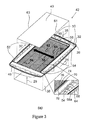
Figure 3 is an exploded bottom view of the membrane support plate ofFigure 2 . -
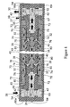
Figure 4 is a cross sectional view of a filtration cartridge of this invention having one filtration unit. -
Figure 5 is a cross-sectional view of a filtration cartridge of this invention having two filtration units. -
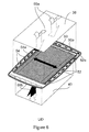
Figure 6 is an exploded view showing the first surface of the membrane support plate ofFigure 2 and showing permeate flow paths within the filtration cartridge. - Referring to
Figure 1 , a self containedfiltration cartridge 20 having, for example, 0.5 square meters of filter area, is shown. Thecartridge 20 comprises anupper end cap 22, alower end cap 24, and a plurality offiltration units 26.Upper end cap 22 is provided with aninlet 28 for feed, anoutlet 30 for permeate and avent 27 to vent gas. Preferably theend caps filtration units 26 are of the same plastic material and are selectively welded together such as with heat or solvent at their outer peripheries. Theinlet 28,outlet 30 andvent 27 are respectively adapted for connection to a conduit of tubing or the like. - The
vent 27 of any suitable type extends through theend cap 22 to permit the venting of air from the filtration cartridge at start-up and to permit venting of a gas to test for membrane defects when operating the filtration cartridge iii20 in TFF mode. This may comprise, for example, a manually opening valve which is opened to exhaust gas and thereafter closed. - In use, a liquid to be filtered enters inlet fitting 28, passes into the stack of
filtration units 26, passes through the filtration membranes within the stack offiltration units 26, as hereinafter described, from which the permeate passes out outlet fitting 30. - Referring to
Figures 2 , and3 , amembrane support plate 32 has a top surface 34 (Figure 2 ) and a bottom surface 36 (Figure 3 ). Thetop surface 34 has a relatively large inner dimension (LID) to accommodate alarger membrane 38 which is larger than themembrane 40. Thebottom surface 36 has a relatively smaller inner dimension (SID) to accommodate thesmaller membrane 40. Thefiltration plate 42 shown inFigures 2 and3 comprises themembrane support plate 32 and the twomembranes membrane support plate 32 atmembrane seal sites filtration unit 26 capable of effecting fluid filtration is formed by joining (sealing) twofiltration plates 42 to each other at the SID to SID surfaces. A stack offiltration units 26 is formed by joining (sealing)filtration units 26 to each other at the LID to LID surfaces. By sealing the SID to SID surfaces and LID to LID surfaces in this manner, a stack of filtration units 26 (Figure 1 ) is formed which is capable of effecting fluid flow there through which assures that all incoming fluid feed is passed through amembrane outlet 30 of the filtration cartridge 20 (Figure 1 ) formed from the stack offiltration units 26. - The
filtration plate 32 ofFigures 2 and3 includes feed inlet holes 48, permeate outlet holes 50, two sets of permeate pathway holes 52 and 54 and vent holes 56. The two permeatepathways Figure 1 ). In use, feed to thefiltration cartridge 20 enters through inlet 28 (Figure 1 ) and passes through feed inlet holes 48 as represented inarrow 29. On the SID side (Figure 3 ), fluid feed passes throughmembrane 40 to produce a permeate which travels in one of two directions as represented by arrow 58 throughgrooves 60. The furthest the permeate travels onplate 32 is from dotted line 62, which is the midpoint of the length of thegrooves 60, to either edge 61 or 63 ofmembrane 40. The permeate, on average, travels from either dottedline 64 or dottedline 66 which are 25% of the length ofgrooves 60 to either edge 61 or 63 ofmembrane 40. The permeate travels through thespaces 68a positioned betweenposts 68 and then through permeate pathway holes 52 or 54 as represented byarrows arrow 35 to the outlet 30 (Figure 1 ). On the LID side (Figure 2 ), fluid feed passes throughmembrane 38 to produce a permeate which travels in one of two directions as represented byarrow 69 through grooves 71. The furthest the permeate travels onplate 32 is from dotted line 73, which is the midpoint of the length of the grooves 73, to either edge 75 or 77 ofmembrane 38. The permeate, on average, travels from either dotted line 79 or dotted line 81 which are 25% of the length of grooves 71 to either edge 75 or 77 ofmembrane 38. The permeate travels through permeate pathway holes 52 or 54 as represented byarrows arrow 35. As shown inFigure 6 , fluid feeds 69a and 69b pass throughmembranes arrows holes 50 as shown byarrows 50a and then to outlet 30 (Figure 1 ). - Referring to
Figure 4 , afiltration unit 26 sealed to endcaps filtration unit 26 comprises twofiltration plates 42 shown inFigures 2 and3 and are shown at the cross section 4-4 ofFigure 2 . Themembrane support plates 32 are sealed together at plate seals 64, 68 and 70.Membranes 38 are sealed to themembrane plates 32 atmembrane seal area 72.Membranes 40 are sealed tomembrane support plates 32 atmembrane seal areas 74.Membrane support plates 32 are provided with an inner row ofholes 76 and an outer row ofholes 78. As shown by the black arrows inFigure 4 , allincoming feed fluid 80 must pass throughmembranes permeate 82. Thefiltration units 26 are sealed at their outer periphery atouter plate seal 64 and at an inner periphery at plate seal 70 (Figure 3 ) on the SID side and at theouter plate seal 66a and inner plate seal on the LID side (Figure 2 ). Theseals surfaces surrounding holes 52 and 54 (Figures 2 and3 ) so as to provide flow paths from theholes holes 50. Afiltration unit 26 is sealed to endcap 65 atperipheral plate seal 66. Afiltration unit 26 is sealed to endcap 65 atperipheral plate seal 69. An inlet (not shown) is provided for introducing feed into thefiltration units 26. Avent 27 and anoutlet 30 also are provided in the manner shown inFigure 1 . Theseals - Referring to
Figure 5 , twofiltration units 26, sealed together are shown. InFigure 5 , the reference numbers which are the same reference numbers inFigure 4 identify the same elements as inFigure 4 .Figure 5 shows that a plurality offiltration units 26 be stacked and sealed together to form a filtration cartridge 20 (Figure 1 ) having twopermeate paths - In use, the integrity of the
membranes vent 27 open. The gas passes frominlet 28, across themembrane 38 to vent 27. - In subsequent operation, the
vent 27 is initially open and fluid feed is introduced throughinlet 28 to produce permeate that replaces gas within thefiltration cartridge 20. Thevent 27 is then closed so that the vent holes 56 (Figures 2 and3 ) are filled with permeate. Excess permeate is removed throughoutlet 30 over the time filtration is effected. After filtration is effected, permeate can more easily be drained from thefiltration cartridge 20 throughoutlet 30 by openingvent 27.
Claims (15)
- A filtration cartridge (20) having a fluid inlet (28) and a fluid outlet (30) comprising,
a top end cap (22;65);
a bottom end cap (24;67);
a vent (27) on at least one of the end caps (22; 65; 24; 67);
at least one filtration unit (26), each comprising two filtration plates (42), wherein each filtration plate has a membrane support plate (32) having at least one filtration membrane (38,40) respectively bonded to a bottom surface (36) of the membrane support plate (32) and to a top surface (34) of the membrane support plate (32), and the membrane support plates (32) of the filtration plates (42) being bonded to each other at an outer peripheral surface to form seals (64,68,70) to prevent fluid feed from entering the fluid outlet (30) except by having passed through at least one of the membranes (38,40); and
fluid flow paths from the fluid inlet (28), through the membranes (38,40) and through the fluid outlet (30) that prevent fluid feed from the inlet (28) from by-passing the membranes (38,40) and which provide a single permeate pathway including a row of holes (50) for permeate to flow to the fluid outlet (30). - The filtration cartridge of claim 1, wherein in each membrane support plate (32) one of the top or bottom surfaces (34,36) has a relatively larger inner dimension (LID) to accommodate the filtration membrane (38) which is larger than the filtration membrane (40) bonded to the other one of the top and bottom surface (34,36), which in return has a relatively smaller inner dimension (SID) to accommodate the smaller filtration membrane (40).
- The filtration cartridge of claim 2, wherein the filtration unit (26) is formed by joining the two filtration plates (42) to each other at the surfaces having the membrane support plate (32) side with the relatively smaller inner dimension (SID).
- The filtration cartridge of claim 3, wherein a stack of filtration units (26) is formed by joining the filtration units (26) to each other at the surfaces having the membrane support plate (32) side with the relatively larger inner dimension (LID).
- The filtration cartridge of any one of claims 1 to 4, wherein the membrane support plates (32) include fluid pathways (50,52,54,60,76,78) which permit permeate flow from the top surface (34) and from the bottom surface (36) of each of the membrane support plates (32) to the fluid outlet (30).
- The filtration cartridge of claim 5, wherein the membrane support plates (32) comprise:feed inlet holes (48),permeate outlet holes (50),two sets of permeate pathway holes (52,54) which each are in communication with the permeate outlet holes (50) and the outlet (30), andan inner row of holes (76) and an outer row of holes (78) providing communication between the top and bottom surfaces (34,36) thereof,wherein the respective holes are arranged so that:on the membrane support plate (32) side with the relatively smaller inner dimension (SID) fluid feed passes through the mebrane (40) to produce a permeate which travels through the inner row of holes (76) to the opposite side of the membrane support plate (32), through the outer row of holes (78) back to the membrane support plate (32) side with the relatively smaller inner dimension (SID), and then through the permeate pathway holes (52,54) and out the permeate holes (50), andon the membrane support plate (32) side with the relatively larger inner dimension (LID) fluid feed passes through the mebrane (38) to produce a permeate which travels through the outer row of holes (78) to the opposite side of the membrane support plate (32), and then through the permeate pathway holes (52,54) and out the permeate holes (50).
- The filtration cartridge of claim 6, wherein the filtration units (26) are sealed at their outer periphery to each other and to the top and bottom end caps with outer plate seals (64,66a), are sealed at the support plate (32) side with the relatively larger inner dimension (LID) to the top and bottom end caps with inner plate seals (59), and are sealed at the membrane support plate (32) side with the relatively smaller inner dimension (SID) to each other with an inner plate seal (70).
- The filtration cartridge of claim 7, wherein the outer and inner plate seals (59,64,66a,70) are raised from the surfaces surrounding the permeate pathway holes (52,54) so as to provide flow paths from the permeate pathway holes (52,54) to the permeate holes (50).
- The filtration cartridge of any one of claims 1 to 8, wherein the fluid pathways comprise grooves (60;71) formed in the top and bottom surfaces (34,36) of the membrane support plates (32) extending between opposite edges (61,63;75,77) of the membranes (40;38).
- The filtration cartridge of any one of claims 1 to 9, wherein the top end cap (22;65) is provided with the fluid inlet (28), with the fluid outlet (30) and with the vent (27).
- The filtration cartridge of any one of claims 1 to 10 wherein each of the end caps (22;65;24;67) includes an open vent (27).
- The filtration cartridge of any one of claims 1 to 11, wherein a plurality of filtration membranes (40a,40b) are bonded to the bottom surface (36) of the membrane support plates (32) and a plurality of filtration membranes (38a,38b) bonded to the top surface (34) of the membrane support plates (32).
- The filtration cartridge of any one of claims 1 to 12, wherein the filtration cartridge is self contained.
- A filtration cartridge having a fluid inlet and a fluid outlet comprising, at least one filtration unit, each comprising two membrane support plates, each of the membrane support plates having at least one filtration membrane bonded to a bottom surface of the membrane support plate and to a top surface of the membrane support plate, the membrane support plates being bonded to each other at an outer peripheral surface to form seals to prevent fluid feed from entering the fluid outlet except by having passed through at least one of the membranes, a top end cap, a bottom end cap, a vent on one of the end caps, and fluid flow paths from the fluid inlet, through the membranes and through the fluid outlet that prevent fluid feed from the inlet from bypassing the membranes and which provide two permeate pathways for permeate to flow to the fluid outlet.
- A filtration cartridge having a fluid inlet and a fluid outlet comprising, a filtration unit, comprising a membrane support plate, the membrane support plate having a filtration membrane bonded to a bottom surface of the membrane support plate and to a top surface of the membrane support plate, the membrane support plate being bonded to a first isolation plate and a deflection plate at an inner peripheral surface and at an outer peripheral surface of the membrane support plate to form seals to prevent fluid feed from entering the fluid outlet except by having passed through at least on of the membranes, a top end cap having the fluid inlet, a bottom end cap having the fluid outlet, a second isolation plate bonded to the top end cap, the first isolation plate bonded to the bottom end cap and to the filtration unit, the deflection plate bonded to the filtration unit and to the second isolation plate, and fluid flow paths form the fluid inlet through the membranes and through the fluid outlet that prevent fluid feed from the inlet from bypassing the membranes.
Applications Claiming Priority (2)
| Application Number | Priority Date | Filing Date | Title |
|---|---|---|---|
| US99742007P | 2007-10-03 | 2007-10-03 | |
| EP08835170 | 2008-09-11 |
Related Parent Applications (1)
| Application Number | Title | Priority Date | Filing Date |
|---|---|---|---|
| EP08835170.5 Division | 2008-09-11 |
Publications (3)
| Publication Number | Publication Date |
|---|---|
| EP2363197A2 true EP2363197A2 (en) | 2011-09-07 |
| EP2363197A3 EP2363197A3 (en) | 2011-12-14 |
| EP2363197B1 EP2363197B1 (en) | 2013-11-27 |
Family
ID=40085755
Family Applications (1)
| Application Number | Title | Priority Date | Filing Date |
|---|---|---|---|
| EP10161691.0A Active EP2363197B1 (en) | 2007-10-03 | 2008-09-11 | Filtration cartridge formed of stacked plates |
Country Status (6)
| Country | Link |
|---|---|
| US (1) | US8936724B2 (en) |
| EP (1) | EP2363197B1 (en) |
| JP (1) | JP4897085B2 (en) |
| CN (2) | CN104785113B (en) |
| ES (1) | ES2439276T3 (en) |
| WO (1) | WO2009045264A2 (en) |
Cited By (6)
| Publication number | Priority date | Publication date | Assignee | Title |
|---|---|---|---|---|
| WO2019233607A1 (en) * | 2018-06-08 | 2019-12-12 | Evcon Gmbh | Modular flow system with internal strut members |
| US11400417B2 (en) | 2018-06-08 | 2022-08-02 | Evcon Gmbh | Modular flow system with enhanced vapor and/or liquid channel configuration |
| US11833473B2 (en) | 2018-06-08 | 2023-12-05 | Evcon Gmbh | Modular flow system with asymmetric or discontinuous liquid passage |
| US11857928B2 (en) | 2018-06-08 | 2024-01-02 | Evcon Gmbh | Multistage membrane distillation apparatus |
| EP4454739A1 (en) | 2023-04-28 | 2024-10-30 | Sartorius Stedim Biotech GmbH | Filtration device, in particular small-scale filtration device for production of biopharmaceuticals |
| US12134075B2 (en) | 2018-06-08 | 2024-11-05 | Evcon Gmbh | Membrane distillation apparatus for producing water |
Families Citing this family (16)
| Publication number | Priority date | Publication date | Assignee | Title |
|---|---|---|---|---|
| JP4897087B2 (en) * | 2007-10-03 | 2012-03-14 | ミリポア・コーポレイション | Laminated plate type filtration cartridge |
| CN103874537B (en) * | 2011-08-10 | 2017-06-20 | Oasys水有限公司 | Plate, frame and spiral winded type film module for Mass and heat transfer |
| ES2466140B2 (en) * | 2011-08-10 | 2015-12-03 | Oasis Water, Inc | MEMBRANE MODULES |
| DE102012002540B4 (en) | 2012-02-09 | 2018-07-19 | Sartorius Stedim Biotech Gmbh | Filter module and modular filter system |
| IN2014DN09456A (en) | 2012-05-30 | 2015-07-17 | Ge Healthcare Bio Sciences Ab | |
| EP2859937A1 (en) * | 2013-10-11 | 2015-04-15 | Statkraft AS | A frame, a flexible element and a system for pressure retarded osmosis power generation |
| SG11201707534RA (en) | 2015-05-08 | 2017-10-30 | Emd Millipore Corp | Film bonded flatpack |
| TWI656995B (en) | 2018-07-12 | 2019-04-21 | 王亮雄 | Webbing height adjustment device |
| US12172108B2 (en) | 2018-08-16 | 2024-12-24 | Emd Millipore Corporation | Closed bioprocessing device |
| KR102394715B1 (en) * | 2018-12-11 | 2022-05-06 | 주식회사 아모그린텍 | filter module for water-purifying device using gravity and water-purifying device including the same |
| CN112387119A (en) * | 2020-09-29 | 2021-02-23 | 杭州科百特过滤器材有限公司 | Filter for removing viruses |
| WO2022108902A1 (en) * | 2020-11-17 | 2022-05-27 | Heejin Lee | Filtration device for bioprocessing |
| USD1121103S1 (en) * | 2021-12-23 | 2026-03-31 | Emd Millipore Corporation | Filter having filter membranes |
| CN114558455B (en) * | 2022-01-14 | 2023-05-02 | 杭州科百特过滤器材有限公司 | Virus filter |
| WO2024148011A1 (en) * | 2023-01-03 | 2024-07-11 | Emd Millipore Corporation | Tangential flow filter with combined permeate outputs and method of filtering |
| WO2026076092A1 (en) * | 2024-10-02 | 2026-04-09 | Donaldson Company, Inc. | Separation cassette assembly |
Citations (1)
| Publication number | Priority date | Publication date | Assignee | Title |
|---|---|---|---|---|
| US4501663A (en) | 1979-11-05 | 1985-02-26 | Millipore Corporation | Filter cartridges and methods and components for making them |
Family Cites Families (36)
| Publication number | Priority date | Publication date | Assignee | Title |
|---|---|---|---|---|
| GB2003053B (en) * | 1977-08-19 | 1982-07-14 | Kuraray Co | Plate type fluid treatment apparatus |
| US4430218A (en) * | 1980-07-18 | 1984-02-07 | Sartorius Gmbh | Separating device for fluids, consisting of support plates and cut sections of a semi-permeable diaphragm |
| GB2093369B (en) * | 1980-09-03 | 1984-07-18 | Nemtec Lab Pty Ltd | Fluid treatment apparatus |
| JPS60155818A (en) | 1984-01-24 | 1985-08-15 | Matsushita Electric Works Ltd | Blower device for cooling exhaust cylinder |
| US4701861A (en) | 1985-05-31 | 1987-10-20 | Pall Corporation | Filter test device |
| JPS6262815A (en) | 1985-09-13 | 1987-03-19 | Asahi Chem Ind Co Ltd | Production of p-phenylene terephthalamide polymer solution |
| JPH0789517B2 (en) | 1985-09-19 | 1995-09-27 | 松下電器産業株式会社 | High frequency output control method for inverter power supply for magnetron |
| JPS6262815U (en) | 1985-10-11 | 1987-04-18 | ||
| JPH084720B2 (en) | 1986-06-30 | 1996-01-24 | 株式会社キッツ | Plate-shaped porous thin film laminated filter and method for producing the same |
| EP0267108A1 (en) | 1986-10-31 | 1988-05-11 | Digital Equipment Corporation | Miniaturized transformer |
| US5868930A (en) | 1986-11-26 | 1999-02-09 | Kopf; Henry B. | Filtration cassette article and filter comprising same |
| JPH064893Y2 (en) | 1987-04-30 | 1994-02-09 | 株式会社土屋製作所 | Precision filter unit |
| US4881176B1 (en) | 1988-01-22 | 1997-06-17 | Thokon Corp | Filter analyzing system |
| JPH0534736Y2 (en) * | 1989-07-11 | 1993-09-02 | ||
| US5057844A (en) * | 1990-03-19 | 1991-10-15 | Rothstein Mark B | Insulated underground antenna and method for utilizing same |
| JP3087447B2 (en) | 1992-04-30 | 2000-09-11 | ブラザー工業株式会社 | Printing device |
| US5282380A (en) | 1992-06-30 | 1994-02-01 | Millipore Corporation | Integrity test for membranes |
| EP0640822B1 (en) | 1993-08-30 | 1998-04-22 | Millipore Investment Holdings Limited | Integrity test for porous structures using acoustic emission |
| DE4342485C1 (en) * | 1993-12-13 | 1995-03-30 | Gore W L & Ass Gmbh | Apparatus for removing gaseous substances from a gas stream |
| DE4432627B4 (en) * | 1994-09-14 | 2008-09-25 | Sartorius Stedim Biotech Gmbh | Filtration unit for the separation of substances with membrane adsorbers |
| US5697114A (en) | 1996-02-29 | 1997-12-16 | Bear Mgc Cutlery Co., Inc. | Folding multi-tool |
| NL1006118C2 (en) | 1997-05-24 | 1998-11-25 | Koninkl Grolsch N V | Device for filtering a fermented liquid. |
| US6067844A (en) | 1997-08-15 | 2000-05-30 | Shell Oil Company | Nondestructive method for detection of defects and the condition of liners in polymer-lined pipes and equipment |
| DE19860253C1 (en) * | 1998-12-24 | 2000-03-30 | Dbb Fuel Cell Engines Gmbh | Stacked modular membrane unit used for the separation of hydrogen from a mixture of gases for supply to a fuel cell |
| ATE245472T1 (en) | 1999-02-26 | 2003-08-15 | United States Filter Corp | METHOD AND DEVICE FOR TESTING MEMBRANE FILTERS |
| DE19923155A1 (en) | 1999-05-20 | 2000-11-23 | Solvay Fluor & Derivate | Process for removing sulfur hexafluoride/nitrogen mixtures from gas-isolated lines comprises contacting the gas mixture with a membrane |
| US20020139741A1 (en) * | 2001-03-27 | 2002-10-03 | Henry Kopf | Integral gasketed filtration cassette article and method of making the same |
| DE10135294B4 (en) | 2001-07-19 | 2011-07-07 | Sartorius Stedim Biotech GmbH, 37079 | Test device for filter systems |
| EP1440304A2 (en) * | 2001-11-02 | 2004-07-28 | Millipore Corporation | Membrane adsorber device |
| KR20070011489A (en) * | 2004-04-13 | 2007-01-24 | 도날드슨 캄파니 인코포레이티드 | Filter Cartridges for Liquid Filtration |
| WO2006044711A1 (en) * | 2004-10-14 | 2006-04-27 | Pall Corporation | Separation elements and methods of making separation elements |
| US7650805B2 (en) | 2005-10-11 | 2010-01-26 | Millipore Corporation | Integrity testable multilayered filter device |
| JP2007125497A (en) | 2005-11-04 | 2007-05-24 | Matsushita Electric Ind Co Ltd | Filter cartridge |
| US20070125497A1 (en) | 2005-12-02 | 2007-06-07 | Lundell Dennis A | Heated tire building core assembly and method |
| US20080257814A1 (en) * | 2007-04-23 | 2008-10-23 | Millipore Corporation | Filtration Cartridge |
| JP4897087B2 (en) * | 2007-10-03 | 2012-03-14 | ミリポア・コーポレイション | Laminated plate type filtration cartridge |
-
2008
- 2008-09-11 WO PCT/US2008/010616 patent/WO2009045264A2/en not_active Ceased
- 2008-09-11 JP JP2010527932A patent/JP4897085B2/en active Active
- 2008-09-11 ES ES10161691.0T patent/ES2439276T3/en active Active
- 2008-09-11 EP EP10161691.0A patent/EP2363197B1/en active Active
- 2008-09-11 CN CN201510126576.7A patent/CN104785113B/en active Active
- 2008-09-11 CN CN200880117438.0A patent/CN102065985B/en active Active
- 2008-09-11 US US12/733,958 patent/US8936724B2/en active Active
Patent Citations (1)
| Publication number | Priority date | Publication date | Assignee | Title |
|---|---|---|---|---|
| US4501663A (en) | 1979-11-05 | 1985-02-26 | Millipore Corporation | Filter cartridges and methods and components for making them |
Cited By (8)
| Publication number | Priority date | Publication date | Assignee | Title |
|---|---|---|---|---|
| WO2019233607A1 (en) * | 2018-06-08 | 2019-12-12 | Evcon Gmbh | Modular flow system with internal strut members |
| US11400417B2 (en) | 2018-06-08 | 2022-08-02 | Evcon Gmbh | Modular flow system with enhanced vapor and/or liquid channel configuration |
| US11712662B2 (en) | 2018-06-08 | 2023-08-01 | Evcon Gmbh | Modular flow system with internal strut members |
| US11833473B2 (en) | 2018-06-08 | 2023-12-05 | Evcon Gmbh | Modular flow system with asymmetric or discontinuous liquid passage |
| US11857928B2 (en) | 2018-06-08 | 2024-01-02 | Evcon Gmbh | Multistage membrane distillation apparatus |
| US12134075B2 (en) | 2018-06-08 | 2024-11-05 | Evcon Gmbh | Membrane distillation apparatus for producing water |
| EP4454739A1 (en) | 2023-04-28 | 2024-10-30 | Sartorius Stedim Biotech GmbH | Filtration device, in particular small-scale filtration device for production of biopharmaceuticals |
| WO2024223903A1 (en) | 2023-04-28 | 2024-10-31 | Sartorius Stedim Biotech Gmbh | Filtration device, in particular small-scale filtration device for production of biopharmaceuticals |
Also Published As
| Publication number | Publication date |
|---|---|
| EP2363197B1 (en) | 2013-11-27 |
| WO2009045264A3 (en) | 2010-10-07 |
| EP2363197A3 (en) | 2011-12-14 |
| US20100282663A1 (en) | 2010-11-11 |
| JP2011507674A (en) | 2011-03-10 |
| CN104785113B (en) | 2017-06-23 |
| CN102065985B (en) | 2015-04-22 |
| WO2009045264A2 (en) | 2009-04-09 |
| US8936724B2 (en) | 2015-01-20 |
| CN102065985A (en) | 2011-05-18 |
| ES2439276T3 (en) | 2014-01-22 |
| JP4897085B2 (en) | 2012-03-14 |
| CN104785113A (en) | 2015-07-22 |
Similar Documents
| Publication | Publication Date | Title |
|---|---|---|
| EP2363197B1 (en) | Filtration cartridge formed of stacked plates | |
| US8911624B2 (en) | Stacked plates filtration cartridge | |
| EP1987869B1 (en) | Filtration cartridge | |
| US7650805B2 (en) | Integrity testable multilayered filter device | |
| US4501663A (en) | Filter cartridges and methods and components for making them | |
| EP1973635B1 (en) | Filtration assembly and methods for making and using same | |
| EP1779913B1 (en) | Filtration device | |
| CA1320141C (en) | Multi-leaf membrane module | |
| EP3294207B1 (en) | Film bonded flatpack | |
| CN114901376A (en) | Filter cassette in a bag and method of using same |
Legal Events
| Date | Code | Title | Description |
|---|---|---|---|
| PUAI | Public reference made under article 153(3) epc to a published international application that has entered the european phase |
Free format text: ORIGINAL CODE: 0009012 |
|
| 17P | Request for examination filed |
Effective date: 20100430 |
|
| AK | Designated contracting states |
Kind code of ref document: A2 Designated state(s): AT BE BG CH CY CZ DE DK EE ES FI FR GB GR HU IE IS IT LI LT LU LV MC MT NL PL PT RO SE SI SK TR |
|
| AX | Request for extension of the european patent |
Extension state: AL BA MK RS |
|
| PUAL | Search report despatched |
Free format text: ORIGINAL CODE: 0009013 |
|
| AK | Designated contracting states |
Kind code of ref document: A3 Designated state(s): AT BE BG CH CY CZ DE DK EE ES FI FR GB GR HU IE IS IT LI LT LU LV MC MT NL PL PT RO SE SI SK TR |
|
| AX | Request for extension of the european patent |
Extension state: AL BA MK RS |
|
| RIC1 | Information provided on ipc code assigned before grant |
Ipc: B01D 65/00 20060101ALI20111107BHEP Ipc: B01D 65/10 20060101ALI20111107BHEP Ipc: B01D 63/08 20060101AFI20111107BHEP |
|
| RAP1 | Party data changed (applicant data changed or rights of an application transferred) |
Owner name: EMD MILLIPORE CORPORATION |
|
| 17Q | First examination report despatched |
Effective date: 20121128 |
|
| GRAP | Despatch of communication of intention to grant a patent |
Free format text: ORIGINAL CODE: EPIDOSNIGR1 |
|
| INTG | Intention to grant announced |
Effective date: 20130604 |
|
| GRAS | Grant fee paid |
Free format text: ORIGINAL CODE: EPIDOSNIGR3 |
|
| GRAA | (expected) grant |
Free format text: ORIGINAL CODE: 0009210 |
|
| AK | Designated contracting states |
Kind code of ref document: B1 Designated state(s): AT BE BG CH CY CZ DE DK EE ES FI FR GB GR HU IE IS IT LI LT LU LV MC MT NL PL PT RO SE SI SK TR |
|
| REG | Reference to a national code |
Ref country code: GB Ref legal event code: FG4D |
|
| REG | Reference to a national code |
Ref country code: CH Ref legal event code: NV Representative=s name: E. BLUM AND CO. AG PATENT- UND MARKENANWAELTE , CH Ref country code: CH Ref legal event code: EP |
|
| REG | Reference to a national code |
Ref country code: AT Ref legal event code: REF Ref document number: 642446 Country of ref document: AT Kind code of ref document: T Effective date: 20131215 |
|
| REG | Reference to a national code |
Ref country code: IE Ref legal event code: FG4D |
|
| REG | Reference to a national code |
Ref country code: ES Ref legal event code: FG2A Ref document number: 2439276 Country of ref document: ES Kind code of ref document: T3 Effective date: 20140122 |
|
| REG | Reference to a national code |
Ref country code: DE Ref legal event code: R096 Ref document number: 602008029042 Country of ref document: DE Effective date: 20140123 |
|
| REG | Reference to a national code |
Ref country code: NL Ref legal event code: T3 |
|
| REG | Reference to a national code |
Ref country code: AT Ref legal event code: MK05 Ref document number: 642446 Country of ref document: AT Kind code of ref document: T Effective date: 20131127 |
|
| REG | Reference to a national code |
Ref country code: LT Ref legal event code: MG4D |
|
| PG25 | Lapsed in a contracting state [announced via postgrant information from national office to epo] |
Ref country code: IS Free format text: LAPSE BECAUSE OF FAILURE TO SUBMIT A TRANSLATION OF THE DESCRIPTION OR TO PAY THE FEE WITHIN THE PRESCRIBED TIME-LIMIT Effective date: 20140327 Ref country code: FI Free format text: LAPSE BECAUSE OF FAILURE TO SUBMIT A TRANSLATION OF THE DESCRIPTION OR TO PAY THE FEE WITHIN THE PRESCRIBED TIME-LIMIT Effective date: 20131127 Ref country code: SE Free format text: LAPSE BECAUSE OF FAILURE TO SUBMIT A TRANSLATION OF THE DESCRIPTION OR TO PAY THE FEE WITHIN THE PRESCRIBED TIME-LIMIT Effective date: 20131127 Ref country code: LT Free format text: LAPSE BECAUSE OF FAILURE TO SUBMIT A TRANSLATION OF THE DESCRIPTION OR TO PAY THE FEE WITHIN THE PRESCRIBED TIME-LIMIT Effective date: 20131127 |
|
| PG25 | Lapsed in a contracting state [announced via postgrant information from national office to epo] |
Ref country code: AT Free format text: LAPSE BECAUSE OF FAILURE TO SUBMIT A TRANSLATION OF THE DESCRIPTION OR TO PAY THE FEE WITHIN THE PRESCRIBED TIME-LIMIT Effective date: 20131127 Ref country code: LV Free format text: LAPSE BECAUSE OF FAILURE TO SUBMIT A TRANSLATION OF THE DESCRIPTION OR TO PAY THE FEE WITHIN THE PRESCRIBED TIME-LIMIT Effective date: 20131127 Ref country code: CY Free format text: LAPSE BECAUSE OF FAILURE TO SUBMIT A TRANSLATION OF THE DESCRIPTION OR TO PAY THE FEE WITHIN THE PRESCRIBED TIME-LIMIT Effective date: 20131127 |
|
| PG25 | Lapsed in a contracting state [announced via postgrant information from national office to epo] |
Ref country code: PT Free format text: LAPSE BECAUSE OF FAILURE TO SUBMIT A TRANSLATION OF THE DESCRIPTION OR TO PAY THE FEE WITHIN THE PRESCRIBED TIME-LIMIT Effective date: 20140327 |
|
| PG25 | Lapsed in a contracting state [announced via postgrant information from national office to epo] |
Ref country code: EE Free format text: LAPSE BECAUSE OF FAILURE TO SUBMIT A TRANSLATION OF THE DESCRIPTION OR TO PAY THE FEE WITHIN THE PRESCRIBED TIME-LIMIT Effective date: 20131127 |
|
| REG | Reference to a national code |
Ref country code: DE Ref legal event code: R097 Ref document number: 602008029042 Country of ref document: DE |
|
| PG25 | Lapsed in a contracting state [announced via postgrant information from national office to epo] |
Ref country code: PL Free format text: LAPSE BECAUSE OF FAILURE TO SUBMIT A TRANSLATION OF THE DESCRIPTION OR TO PAY THE FEE WITHIN THE PRESCRIBED TIME-LIMIT Effective date: 20131127 Ref country code: SK Free format text: LAPSE BECAUSE OF FAILURE TO SUBMIT A TRANSLATION OF THE DESCRIPTION OR TO PAY THE FEE WITHIN THE PRESCRIBED TIME-LIMIT Effective date: 20131127 Ref country code: CZ Free format text: LAPSE BECAUSE OF FAILURE TO SUBMIT A TRANSLATION OF THE DESCRIPTION OR TO PAY THE FEE WITHIN THE PRESCRIBED TIME-LIMIT Effective date: 20131127 |
|
| PG25 | Lapsed in a contracting state [announced via postgrant information from national office to epo] |
Ref country code: DK Free format text: LAPSE BECAUSE OF FAILURE TO SUBMIT A TRANSLATION OF THE DESCRIPTION OR TO PAY THE FEE WITHIN THE PRESCRIBED TIME-LIMIT Effective date: 20131127 |
|
| PLBE | No opposition filed within time limit |
Free format text: ORIGINAL CODE: 0009261 |
|
| STAA | Information on the status of an ep patent application or granted ep patent |
Free format text: STATUS: NO OPPOSITION FILED WITHIN TIME LIMIT |
|
| 26N | No opposition filed |
Effective date: 20140828 |
|
| REG | Reference to a national code |
Ref country code: DE Ref legal event code: R097 Ref document number: 602008029042 Country of ref document: DE Effective date: 20140828 |
|
| PG25 | Lapsed in a contracting state [announced via postgrant information from national office to epo] |
Ref country code: SI Free format text: LAPSE BECAUSE OF FAILURE TO SUBMIT A TRANSLATION OF THE DESCRIPTION OR TO PAY THE FEE WITHIN THE PRESCRIBED TIME-LIMIT Effective date: 20131127 |
|
| PG25 | Lapsed in a contracting state [announced via postgrant information from national office to epo] |
Ref country code: MC Free format text: LAPSE BECAUSE OF FAILURE TO SUBMIT A TRANSLATION OF THE DESCRIPTION OR TO PAY THE FEE WITHIN THE PRESCRIBED TIME-LIMIT Effective date: 20131127 Ref country code: LU Free format text: LAPSE BECAUSE OF FAILURE TO SUBMIT A TRANSLATION OF THE DESCRIPTION OR TO PAY THE FEE WITHIN THE PRESCRIBED TIME-LIMIT Effective date: 20140911 |
|
| REG | Reference to a national code |
Ref country code: IE Ref legal event code: MM4A |
|
| PG25 | Lapsed in a contracting state [announced via postgrant information from national office to epo] |
Ref country code: IE Free format text: LAPSE BECAUSE OF NON-PAYMENT OF DUE FEES Effective date: 20140911 |
|
| PG25 | Lapsed in a contracting state [announced via postgrant information from national office to epo] |
Ref country code: BG Free format text: LAPSE BECAUSE OF FAILURE TO SUBMIT A TRANSLATION OF THE DESCRIPTION OR TO PAY THE FEE WITHIN THE PRESCRIBED TIME-LIMIT Effective date: 20131127 Ref country code: RO Free format text: LAPSE BECAUSE OF FAILURE TO SUBMIT A TRANSLATION OF THE DESCRIPTION OR TO PAY THE FEE WITHIN THE PRESCRIBED TIME-LIMIT Effective date: 20131127 |
|
| PG25 | Lapsed in a contracting state [announced via postgrant information from national office to epo] |
Ref country code: GR Free format text: LAPSE BECAUSE OF FAILURE TO SUBMIT A TRANSLATION OF THE DESCRIPTION OR TO PAY THE FEE WITHIN THE PRESCRIBED TIME-LIMIT Effective date: 20140228 Ref country code: MT Free format text: LAPSE BECAUSE OF FAILURE TO SUBMIT A TRANSLATION OF THE DESCRIPTION OR TO PAY THE FEE WITHIN THE PRESCRIBED TIME-LIMIT Effective date: 20131127 |
|
| PG25 | Lapsed in a contracting state [announced via postgrant information from national office to epo] |
Ref country code: TR Free format text: LAPSE BECAUSE OF FAILURE TO SUBMIT A TRANSLATION OF THE DESCRIPTION OR TO PAY THE FEE WITHIN THE PRESCRIBED TIME-LIMIT Effective date: 20131127 Ref country code: HU Free format text: LAPSE BECAUSE OF FAILURE TO SUBMIT A TRANSLATION OF THE DESCRIPTION OR TO PAY THE FEE WITHIN THE PRESCRIBED TIME-LIMIT; INVALID AB INITIO Effective date: 20080911 |
|
| REG | Reference to a national code |
Ref country code: FR Ref legal event code: PLFP Year of fee payment: 9 |
|
| REG | Reference to a national code |
Ref country code: FR Ref legal event code: PLFP Year of fee payment: 10 |
|
| REG | Reference to a national code |
Ref country code: FR Ref legal event code: PLFP Year of fee payment: 11 |
|
| P01 | Opt-out of the competence of the unified patent court (upc) registered |
Effective date: 20230602 |
|
| PGFP | Annual fee paid to national office [announced via postgrant information from national office to epo] |
Ref country code: NL Payment date: 20250820 Year of fee payment: 18 |
|
| REG | Reference to a national code |
Ref country code: CH Ref legal event code: U11 Free format text: ST27 STATUS EVENT CODE: U-0-0-U10-U11 (AS PROVIDED BY THE NATIONAL OFFICE) Effective date: 20251001 |
|
| PGFP | Annual fee paid to national office [announced via postgrant information from national office to epo] |
Ref country code: DE Payment date: 20250820 Year of fee payment: 18 |
|
| PGFP | Annual fee paid to national office [announced via postgrant information from national office to epo] |
Ref country code: IT Payment date: 20250820 Year of fee payment: 18 |
|
| PGFP | Annual fee paid to national office [announced via postgrant information from national office to epo] |
Ref country code: BE Payment date: 20250820 Year of fee payment: 18 Ref country code: GB Payment date: 20250822 Year of fee payment: 18 |
|
| PGFP | Annual fee paid to national office [announced via postgrant information from national office to epo] |
Ref country code: FR Payment date: 20250821 Year of fee payment: 18 |
|
| PGFP | Annual fee paid to national office [announced via postgrant information from national office to epo] |
Ref country code: CH Payment date: 20251001 Year of fee payment: 18 |
|
| PGFP | Annual fee paid to national office [announced via postgrant information from national office to epo] |
Ref country code: ES Payment date: 20251001 Year of fee payment: 18 |