EP2363082A2 - Flexible drill and method of joining nitinol to dissimilar metals - Google Patents
Flexible drill and method of joining nitinol to dissimilar metals Download PDFInfo
- Publication number
- EP2363082A2 EP2363082A2 EP11250245A EP11250245A EP2363082A2 EP 2363082 A2 EP2363082 A2 EP 2363082A2 EP 11250245 A EP11250245 A EP 11250245A EP 11250245 A EP11250245 A EP 11250245A EP 2363082 A2 EP2363082 A2 EP 2363082A2
- Authority
- EP
- European Patent Office
- Prior art keywords
- nitinol
- shaft
- drill
- flexible
- stainless steel
- Prior art date
- Legal status (The legal status is an assumption and is not a legal conclusion. Google has not performed a legal analysis and makes no representation as to the accuracy of the status listed.)
- Granted
Links
- 229910001000 nickel titanium Inorganic materials 0.000 title claims abstract description 82
- HLXZNVUGXRDIFK-UHFFFAOYSA-N nickel titanium Chemical compound [Ti].[Ti].[Ti].[Ti].[Ti].[Ti].[Ti].[Ti].[Ti].[Ti].[Ti].[Ni].[Ni].[Ni].[Ni].[Ni].[Ni].[Ni].[Ni].[Ni].[Ni].[Ni].[Ni].[Ni].[Ni] HLXZNVUGXRDIFK-UHFFFAOYSA-N 0.000 title claims abstract description 82
- 229910052751 metal Inorganic materials 0.000 title claims description 24
- 239000002184 metal Substances 0.000 title claims description 24
- 238000005304 joining Methods 0.000 title claims description 20
- 238000000034 method Methods 0.000 title claims description 20
- 150000002739 metals Chemical class 0.000 title description 2
- 229910001220 stainless steel Inorganic materials 0.000 claims abstract description 44
- 239000010935 stainless steel Substances 0.000 claims abstract description 44
- 229920001684 low density polyethylene Polymers 0.000 claims abstract description 11
- 239000004702 low-density polyethylene Substances 0.000 claims abstract description 11
- 238000003466 welding Methods 0.000 claims description 23
- 239000011248 coating agent Substances 0.000 claims description 7
- 238000000576 coating method Methods 0.000 claims description 7
- 239000000945 filler Substances 0.000 claims description 5
- RVTZCBVAJQQJTK-UHFFFAOYSA-N oxygen(2-);zirconium(4+) Chemical group [O-2].[O-2].[Zr+4] RVTZCBVAJQQJTK-UHFFFAOYSA-N 0.000 claims description 5
- 229920001296 polysiloxane Polymers 0.000 claims description 2
- 239000004811 fluoropolymer Substances 0.000 abstract description 3
- 229920002313 fluoropolymer Polymers 0.000 abstract description 3
- 239000000463 material Substances 0.000 description 20
- 238000005520 cutting process Methods 0.000 description 7
- 238000005553 drilling Methods 0.000 description 6
- 229920001343 polytetrafluoroethylene Polymers 0.000 description 5
- 239000004810 polytetrafluoroethylene Substances 0.000 description 5
- PXHVJJICTQNCMI-UHFFFAOYSA-N Nickel Chemical compound [Ni] PXHVJJICTQNCMI-UHFFFAOYSA-N 0.000 description 4
- 239000000956 alloy Substances 0.000 description 3
- 210000000988 bone and bone Anatomy 0.000 description 3
- -1 polytetrafluoroethylene Polymers 0.000 description 3
- 238000001356 surgical procedure Methods 0.000 description 3
- XEEYBQQBJWHFJM-UHFFFAOYSA-N Iron Chemical compound [Fe] XEEYBQQBJWHFJM-UHFFFAOYSA-N 0.000 description 2
- KDLHZDBZIXYQEI-UHFFFAOYSA-N Palladium Chemical compound [Pd] KDLHZDBZIXYQEI-UHFFFAOYSA-N 0.000 description 2
- 229910045601 alloy Inorganic materials 0.000 description 2
- 238000005275 alloying Methods 0.000 description 2
- 238000012986 modification Methods 0.000 description 2
- 230000004048 modification Effects 0.000 description 2
- 229910052759 nickel Inorganic materials 0.000 description 2
- BASFCYQUMIYNBI-UHFFFAOYSA-N platinum Chemical compound [Pt] BASFCYQUMIYNBI-UHFFFAOYSA-N 0.000 description 2
- 229920000642 polymer Polymers 0.000 description 2
- 239000007787 solid Substances 0.000 description 2
- BFKJFAAPBSQJPD-UHFFFAOYSA-N tetrafluoroethene Chemical group FC(F)=C(F)F BFKJFAAPBSQJPD-UHFFFAOYSA-N 0.000 description 2
- 210000001519 tissue Anatomy 0.000 description 2
- RYGMFSIKBFXOCR-UHFFFAOYSA-N Copper Chemical compound [Cu] RYGMFSIKBFXOCR-UHFFFAOYSA-N 0.000 description 1
- CWYNVVGOOAEACU-UHFFFAOYSA-N Fe2+ Chemical compound [Fe+2] CWYNVVGOOAEACU-UHFFFAOYSA-N 0.000 description 1
- RTAQQCXQSZGOHL-UHFFFAOYSA-N Titanium Chemical compound [Ti] RTAQQCXQSZGOHL-UHFFFAOYSA-N 0.000 description 1
- HZEWFHLRYVTOIW-UHFFFAOYSA-N [Ti].[Ni] Chemical compound [Ti].[Ni] HZEWFHLRYVTOIW-UHFFFAOYSA-N 0.000 description 1
- 230000003542 behavioural effect Effects 0.000 description 1
- 238000005452 bending Methods 0.000 description 1
- 230000015572 biosynthetic process Effects 0.000 description 1
- 238000005253 cladding Methods 0.000 description 1
- 229910017052 cobalt Inorganic materials 0.000 description 1
- 239000010941 cobalt Substances 0.000 description 1
- GUTLYIVDDKVIGB-UHFFFAOYSA-N cobalt atom Chemical compound [Co] GUTLYIVDDKVIGB-UHFFFAOYSA-N 0.000 description 1
- 229910052802 copper Inorganic materials 0.000 description 1
- 239000010949 copper Substances 0.000 description 1
- 230000007812 deficiency Effects 0.000 description 1
- 230000001419 dependent effect Effects 0.000 description 1
- 238000000151 deposition Methods 0.000 description 1
- 238000013461 design Methods 0.000 description 1
- 238000001125 extrusion Methods 0.000 description 1
- 230000004927 fusion Effects 0.000 description 1
- 238000001746 injection moulding Methods 0.000 description 1
- 238000003780 insertion Methods 0.000 description 1
- 230000037431 insertion Effects 0.000 description 1
- 229910052742 iron Inorganic materials 0.000 description 1
- 210000003127 knee Anatomy 0.000 description 1
- 238000004093 laser heating Methods 0.000 description 1
- 229910052763 palladium Inorganic materials 0.000 description 1
- 229910052697 platinum Inorganic materials 0.000 description 1
- 238000012545 processing Methods 0.000 description 1
- 229910001285 shape-memory alloy Inorganic materials 0.000 description 1
- 238000005507 spraying Methods 0.000 description 1
- 239000000126 substance Substances 0.000 description 1
- 239000010936 titanium Substances 0.000 description 1
- 229910052719 titanium Inorganic materials 0.000 description 1
- 229910052720 vanadium Inorganic materials 0.000 description 1
- LEONUFNNVUYDNQ-UHFFFAOYSA-N vanadium atom Chemical compound [V] LEONUFNNVUYDNQ-UHFFFAOYSA-N 0.000 description 1
Images


Classifications
-
- A—HUMAN NECESSITIES
- A61—MEDICAL OR VETERINARY SCIENCE; HYGIENE
- A61B—DIAGNOSIS; SURGERY; IDENTIFICATION
- A61B17/00—Surgical instruments, devices or methods
- A61B17/16—Instruments for performing osteoclasis; Drills or chisels for bones; Trepans
- A61B17/1613—Component parts
- A61B17/1631—Special drive shafts, e.g. flexible shafts
-
- A—HUMAN NECESSITIES
- A61—MEDICAL OR VETERINARY SCIENCE; HYGIENE
- A61B—DIAGNOSIS; SURGERY; IDENTIFICATION
- A61B17/00—Surgical instruments, devices or methods
- A61B2017/00526—Methods of manufacturing
-
- A—HUMAN NECESSITIES
- A61—MEDICAL OR VETERINARY SCIENCE; HYGIENE
- A61B—DIAGNOSIS; SURGERY; IDENTIFICATION
- A61B17/00—Surgical instruments, devices or methods
- A61B2017/00831—Material properties
- A61B2017/00867—Material properties shape memory effect
-
- A—HUMAN NECESSITIES
- A61—MEDICAL OR VETERINARY SCIENCE; HYGIENE
- A61B—DIAGNOSIS; SURGERY; IDENTIFICATION
- A61B17/00—Surgical instruments, devices or methods
- A61B2017/00831—Material properties
- A61B2017/00867—Material properties shape memory effect
- A61B2017/00871—Material properties shape memory effect polymeric
-
- A—HUMAN NECESSITIES
- A61—MEDICAL OR VETERINARY SCIENCE; HYGIENE
- A61B—DIAGNOSIS; SURGERY; IDENTIFICATION
- A61B17/00—Surgical instruments, devices or methods
- A61B17/32—Surgical cutting instruments
- A61B17/320016—Endoscopic cutting instruments, e.g. arthroscopes, resectoscopes
- A61B17/32002—Endoscopic cutting instruments, e.g. arthroscopes, resectoscopes with continuously rotating, oscillating or reciprocating cutting instruments
- A61B2017/320032—Details of the rotating or oscillating shaft, e.g. using a flexible shaft
Definitions
- the present invention relates to arthroscopic surgical methods and instruments and, more specifically, to a flexible drill instrument using a nitinol shaft and a low friction bearing, and to methods of joining a nitinol shaft portion to a shaft portion formed of a dissimilar metal such as stainless steel.
- Surgical cutting instruments in which an inner member is rotated within a tubular outer member are known in the art.
- the tubular outer member includes a distal end with an opening defining a cutting port or window and the inner member includes a distal end with a cutting tip for engaging bodily tissue via the opening.
- Proximal ends of the inner and outer members commonly include hubs which attach to a handpiece having a motor for rotating the inner member relative to the outer member.
- the distal end of the inner member can have various configurations dependent upon the surgical procedure to be performed, with the opening in the distal end of the outer member being suitably configured to cooperate with the particular configuration of the distal end of the inner member to cut, resect or abrade tissue.
- the tubular inner and outer members are straight.
- straight cutting instruments For example, in arthroscopic knee, hip or shoulder surgery it is well known to use curved cutting instruments which can be positioned at various desired angles relative to the surface of the bone.
- the present invention provides a flexible drill which includes a nitinol portion of the shaft, to increase the flexibility of the shaft while maintaining sufficient column strength for the instrument during a cutting/drilling operation. Also provided is a novel method of joining (welding) a nitinol portion of a shaft to an adjacent portion of a shaft formed of a dissimilar metal, for example, joining (welding) a nitinol portion of a shaft to an adjacent stainless steel portion of the shaft.
- the present invention provides a flexible drill with a shaft having a nitinol portion (or nitinol region) provided between a stainless steel driver end and a stainless steel drill tip.
- the flexible drill using the nitinol shaft of the present invention may be provided with a bearing surface to allow centering within a drill guide, low friction bearing and flexibility to drill around a curve.
- the bearing surface may be formed of a polymer, for example, a fluoropolymer of tetrafluoroethylene such as polytetrafluoroethylene (PTFE) or LDPE (Low Density Polyethylene).
- the novel drill shaft of the present invention may be preferably used through a drill guide such as a curved drill sleeve.
- the invention also provides a method of joining (directly welding or fusing) nitinol (nickel-titanium alloy) to a dissimilar metal by inter alia: (i) providing cross-holes in a tubular member formed of a material dissimilar to nitinol; (ii) inserting a nitinol piece to be welded within at least a portion of the tubular member; and (iii) creating "plug" welds using laser in the cross-holes.
- FIG. 1 illustrates a lateral view of a flexible drill shaft of the present invention (with a nitinol shaft provided between a drive end and a drill tip);
- FIG. 2 illustrates an enlarged cross-sectional view of the flexible, nitinol portion of the flexible drill shaft of FIG. 1 , taken along line A-A;
- FIG. 3 illustrates a cross-sectional partial view of a shaft undergoing welding of a nitinol portion to a stainless steel portion, and according to a method of joining different materials of the present invention
- FIG. 4 illustrates an enlarged view of the welding regions of the shaft of FIG. 3 , depicting the heat affected zones (by the welding) and the high stress zones (which are not affected by the welding);
- FIG. 5a illustrates a top view of a curved drill guide into which the flexible drill of the present invention is passed
- FIG. 5b illustrates a side view of the curved drill guide of FIG. 5a ;
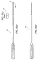
- FIG. 6a illustrates a partial cross-sectional view of a driver with a flexible shaft for placing an anchor through the sleeve once the flexible drill has created a hole in bone for receiving the anchor;
- FIG. 6b illustrates a top view of the driver of FIG. 6a ;
- FIG. 6c illustrates an enlarged view of the most distal end of the driver of FIG. 6a .
- the present invention provides a flexible drill with a shaft having a nitinol portion (or nitinol region) provided between a stainless steel driver end and a stainless steel drill tip.
- the flexible drill with nitinol shaft of the present invention may be provided with a bearing surface to allow centering within a drill guide, low friction bearing and flexibility to drill around a curve.
- the bearing surface may be formed of a polymer, for example, a fluoropolymer of tetrafluoroethylene such as polytetrafluoroethylene (PTFE) or LDPE (Low Density Polyethylene).
- the novel drill shaft of the present invention may be preferably used through a drill guide such as a curved drill sleeve.
- the invention also provides a method of joining (directly welding or fusing) nitinol (nickel-titanium alloy) to a dissimilar metal by inter alia: (i) providing cross-holes in a tubular member formed of a material dissimilar to nitinol; (ii) inserting a nitinol piece to be welded within at least a portion of the tubular member; and (iii) creating "plug" welds using laser in the cross-holes.
- the invention also provides a method of joining (directly welding) a first member formed of nitinol to a second member formed of a dissimilar metal such as stainless steel (or a material similar to stainless steel).
- the method of the present invention comprises inter alia the steps of: (i) providing a first member formed of nitinol adjacent a second member formed of a dissimilar metal; (ii) drilling a plurality of cross-holes through the second member formed of dissimilar metal; (iii) inserting the first member to be welded within the second member; and (iv) creating "plug" welds using laser in the cross-holes, to keep the weld away from the joint regions (high stress regions).
- the invention also provides a method of joining (directly welding) materials which have different physical and chemical characteristics, for example, for joining (directly welding) nitinol to a dissimilar metal such as stainless steel or a material similar to stainless steel.
- the method of the present invention comprises inter alia the steps of: (i) providing a part of a shaft formed of nitinol adjacent another part of the shaft formed of a dissimilar metal; (ii) drilling a plurality of cross-holes through the part of the shaft formed of dissimilar metal; (iii) inserting the part of the shaft formed of nitinol to be welded within the dissimilar metal part; and (iv) creating "plug" welds using laser in the cross-holes, to keep the weld away from the joint regions (high stress regions). In this manner, the heat is kept away from the high stress regions (i.e., the regions which are subjected to most torque during the flexing and/or bending of the shaft).
- the method of the present invention comprises inter alia the steps of: (i) providing a rigid part of a shaft formed of stainless steel adjacent a flexible part of the shaft formed of nitinol; (ii) drilling a plurality of cross-holes through the rigid part of the shaft formed of stainless steel; (iii) inserting the flexible part of the shaft formed of nitinol to be welded within the stainless steel part; and (iv) creating "plug" welds using laser in the cross-holes, to keep the weld away from the joint regions (high stress regions).
- the rigid part of the shaft may be a driver end or a drill tip.
- FIGS. 1 and 2 illustrate a flexible drill 10 with a shaft having a flexible nitinol portion 15 (or nitinol region 15 or core region 15) provided between a rigid driver end 13 and a drill tip 17, both the driver end 13 and the drill tip 17 being formed of a dissimilar material, i.e., a material which is substantially different from nitinol, such as for example, stainless steel or other ferrous material.
- a dissimilar material i.e., a material which is substantially different from nitinol, such as for example, stainless steel or other ferrous material.
- flexible drill 10 comprises a shaft having a flexible nitinol portion 15 (a nitinol core or wire 15) that consists essentially of nitinol and that is placed between, and in direct contact, with a rigid stainless steel driver end 13 (a cut tubular member 13) and a rigid stainless steel drill tip 17.
- the flexible nitinol portion 15 may be in the form of a core or wire 15 or, alternatively, in the shape of a cut tubular member 15.
- the nitinol portion 15 is essentially formed of a shape-memory alloy with superelastic properties, for example, a psuedoelastic alloy material preferably consisting essentially of about 30 to about 52% titanium with the balance nickel and optionally up to 10% of one or more other alloying elements (which are selected from the group consisting of iron, cobalt, vanadium, platinum, palladium and copper).
- a shape-memory alloy with superelastic properties for example, a psuedoelastic alloy material preferably consisting essentially of about 30 to about 52% titanium with the balance nickel and optionally up to 10% of one or more other alloying elements (which are selected from the group consisting of iron, cobalt, vanadium, platinum, palladium and copper).
- the nitinol shaft 15 is centered in the drill guide and cannot unwind, yet providing flexibility to drill around a curve.
- the flexible drill 10 using the flexible nitinol shaft of the present invention is provided with a coating 20, for example, a polymeric coating such as a PTFE or LDPE (Low Density Polyethylene) bearing surface 20 to allow centering within the drill guide (shown in FIGS. 5a and 5b ), low friction bearing and flexibility to drill around a curve.
- the polymeric coating may be applied by co-extrusion, spray coating or other surface deposition techniques known in the art. If LDPE is employed for the bearing surface 20, the LDPE material may be preferably provided on the nitinol region by injection molding to save processing time.
- FIG. 2 is a cross-sectional view of the flexible portion or region 15 of the flexible drill 10 of FIG. 1 , taken along line A-A of FIG. 1 .
- flexible nitinol portion 15 is in the form of a nitinol core 15 (nitinol wire 15) which is surrounded by a flexible filler 22, which in turn is provided between the nitinol surface 15a and the polymeric coating for bearing 20.
- the flexible filler 22 may be silicone or a Si 2 C variant or a similar material.
- the flexible filler 22 may be provided on substantially the whole length/surface of the nitinol surface 15a of the nitinol wire 15 or, alternatively, may be provided at least on a nitinol surface located at a distal end and a proximal end of the flexible nitinol region 15 (to allow joining of the nitinol to the driver end the drill tip formed of a dissimilar metal such as stainless steel).
- FIGS. 5a and 5b illustrate a top view and a side view, respectively, of a curved drill guide 80 into which the flexible drill 10 of the present invention is passed.
- the flexible nitinol shaft 15 is centered in the curved drill guide 80 and cannot unwind, yet provides flexibility to drill around a curve.
- FIGS. 6a and 6b illustrate a driver 100 which is used to place an anchor in the hole in bone formed by the flexible drill of the present invention.
- FIG. 6c illustrates an end view of the most proximal end 102 of the driver 100.
- nitinol in the distal section only of the shaft of the flexible drill 10 and a more economical material metal tube (such as a more cost-effective alloy like stainless steel) in the proximal section, both the performance and the overall design of the shaft are optimized.
- the desired connection between nitinol and stainless steel is achieved without causing deficiencies in the strength and behavioral properties of the ends of nitinol shaft attached, on each side, to the stainless steel members (i.e., to the rigid driver end 13 and the rigid drill tip 17).
- FIGS. 3 and 4 detail a method of joining different materials of the present invention (for example, nitinol and stainless steel).
- nitinol and stainless steel for example, nickel-titanium alloys
- the invention is not limited to this particular exemplary embodiment only, and has applicability to the joining/welding/fusing of nitinol (or nickel-titanium alloys) to any other dissimilar metal (i.e., any metal in addition to stainless steel).
- FIG. 3 illustrates a partial cross-sectional view of a shaft/tubular member undergoing joining/welding of a nitinol portion 50 (nitinol shaft or core, or first member 50) to a stainless steel portion 60 (stainless steel shaft or second tubular member 60), and according to a method of joining different materials of the present invention.
- the method comprises inter alia the steps of: (i) providing a first member 50 formed of nitinol adjacent a second tubular member 60 formed of a dissimilar metal; (ii) drilling a plurality of cross-holes 66 through the second tubular member 60 formed of dissimilar metal; (iii) inserting the first member 50 within the second tubular member 60; and (iv) creating "plug" welds 70 using laser in the cross-holes 66, to keep the weld away from the joint regions 77 (high stress regions 77).
- the nitinol portion 50 corresponds to the flexible nitinol core or wire 15 of FIG. 1
- the stainless steel portion 60 corresponds to the stainless steel driver end 13 or the driver tip 17 of FIG. 1 .
- Second tubular member may be a solid member or, alternatively, a cannulated member.
- Cross-holes 66 are provided at a distance "d" ( FIGS. 3 and 4 ) from the most distal end 60a of second tubular member 60 to ensure that the heat (and the heat affected zones 78 ( FIG. 4 )) are kept away from the high stress regions, which are the regions where the joints between nitinol and the dissimilar metal (stainless steel) occur (i.e., the regions between the stainless steel distal portion 60a and the nitinol proximal portion 51). Holes 66 are formed by drilling across the diameter of the tubular member 60 (i.e., from a top surface 61 to a bottom surface 63). Once the nitinol member 50 is inserted within the second member 60, cross-holes interface the top surface 50a of the nitinol member 50.
- Joining/welding of the nitinol to the dissimilar metal may be achieved by fusion welding such as pulse laser welding, cladding or alloying using laser. These laser joining processes essentially include laser heating of areas where the two different metals (the nitinol and the stainless steel) interface, i.e., at the bottoms of holes 66.
- Figure 4 illustrates an enlarged view of the welding region of the shaft of Figure 3 , depicting the heat affected zones 78 (by the welding) and the unaffected high stress zones 77 (which are not affected by the welding and which correspond to the interface between most distal end 60a of stainless steel member 60 and proximal end 51 of nitinol wire 50).
- the laser welds the bottom of the holes 66 and eliminates the need for additional pieces of intermediary material (such as a nickel piece) provided between the stainless steel shaft and the nitinol shaft, to facilitate welding of these two dissimilar materials.
- the method of the present invention provides a simpler, faster and more efficient way of welding nitinol to a material different from it (such as stainless steel).
- the invention provides an improved, simpler and faster method of laser joining a first nitinol member to a second member, with no intermediate material necessary (for example, with no intermediate piece or material disposed between the nitinol member and the second tubular member).
Landscapes
- Health & Medical Sciences (AREA)
- Surgery (AREA)
- Life Sciences & Earth Sciences (AREA)
- Biomedical Technology (AREA)
- Medical Informatics (AREA)
- Orthopedic Medicine & Surgery (AREA)
- Oral & Maxillofacial Surgery (AREA)
- Engineering & Computer Science (AREA)
- Dentistry (AREA)
- Heart & Thoracic Surgery (AREA)
- Nuclear Medicine, Radiotherapy & Molecular Imaging (AREA)
- Molecular Biology (AREA)
- Animal Behavior & Ethology (AREA)
- General Health & Medical Sciences (AREA)
- Public Health (AREA)
- Veterinary Medicine (AREA)
- Laser Beam Processing (AREA)
- Drilling And Boring (AREA)
- Prostheses (AREA)
Abstract
Description
- The present invention relates to arthroscopic surgical methods and instruments and, more specifically, to a flexible drill instrument using a nitinol shaft and a low friction bearing, and to methods of joining a nitinol shaft portion to a shaft portion formed of a dissimilar metal such as stainless steel.
- Surgical cutting instruments in which an inner member is rotated within a tubular outer member are known in the art. Typically, the tubular outer member includes a distal end with an opening defining a cutting port or window and the inner member includes a distal end with a cutting tip for engaging bodily tissue via the opening. Proximal ends of the inner and outer members commonly include hubs which attach to a handpiece having a motor for rotating the inner member relative to the outer member. The distal end of the inner member can have various configurations dependent upon the surgical procedure to be performed, with the opening in the distal end of the outer member being suitably configured to cooperate with the particular configuration of the distal end of the inner member to cut, resect or abrade tissue.
- Often the tubular inner and outer members are straight. In many surgical procedures, however, it is desirable for the cutting instruments to be bent or curved to access surgical sites which are generally not accessible with straight cutting instruments. For example, in arthroscopic knee, hip or shoulder surgery it is well known to use curved cutting instruments which can be positioned at various desired angles relative to the surface of the bone.
- The present invention provides a flexible drill which includes a nitinol portion of the shaft, to increase the flexibility of the shaft while maintaining sufficient column strength for the instrument during a cutting/drilling operation. Also provided is a novel method of joining (welding) a nitinol portion of a shaft to an adjacent portion of a shaft formed of a dissimilar metal, for example, joining (welding) a nitinol portion of a shaft to an adjacent stainless steel portion of the shaft.
- The present invention provides a flexible drill with a shaft having a nitinol portion (or nitinol region) provided between a stainless steel driver end and a stainless steel drill tip. The flexible drill using the nitinol shaft of the present invention may be provided with a bearing surface to allow centering within a drill guide, low friction bearing and flexibility to drill around a curve. The bearing surface may be formed of a polymer, for example, a fluoropolymer of tetrafluoroethylene such as polytetrafluoroethylene (PTFE) or LDPE (Low Density Polyethylene). The novel drill shaft of the present invention may be preferably used through a drill guide such as a curved drill sleeve.
- The invention also provides a method of joining (directly welding or fusing) nitinol (nickel-titanium alloy) to a dissimilar metal by inter alia: (i) providing cross-holes in a tubular member formed of a material dissimilar to nitinol; (ii) inserting a nitinol piece to be welded within at least a portion of the tubular member; and (iii) creating "plug" welds using laser in the cross-holes.
- These and other features and advantages of the invention will be more apparent from the following detailed description that is provided in connection with the accompanying drawings and illustrated exemplary embodiments of the invention.
-
FIG. 1 illustrates a lateral view of a flexible drill shaft of the present invention (with a nitinol shaft provided between a drive end and a drill tip); -
FIG. 2 illustrates an enlarged cross-sectional view of the flexible, nitinol portion of the flexible drill shaft ofFIG. 1 , taken along line A-A; -
FIG. 3 illustrates a cross-sectional partial view of a shaft undergoing welding of a nitinol portion to a stainless steel portion, and according to a method of joining different materials of the present invention; -
FIG. 4 illustrates an enlarged view of the welding regions of the shaft ofFIG. 3 , depicting the heat affected zones (by the welding) and the high stress zones (which are not affected by the welding); -
FIG. 5a illustrates a top view of a curved drill guide into which the flexible drill of the present invention is passed; -
FIG. 5b illustrates a side view of the curved drill guide ofFIG. 5a ; -
FIG. 6a illustrates a partial cross-sectional view of a driver with a flexible shaft for placing an anchor through the sleeve once the flexible drill has created a hole in bone for receiving the anchor; -
FIG. 6b illustrates a top view of the driver ofFIG. 6a ; and -
FIG. 6c illustrates an enlarged view of the most distal end of the driver ofFIG. 6a . - The following description is provided to enable any person skilled in the art to make and use the invention and sets forth the best modes contemplated by the inventors of carrying out their invention. Various modifications, however, will remain readily apparent to those skilled in the art.
- The present invention provides a flexible drill with a shaft having a nitinol portion (or nitinol region) provided between a stainless steel driver end and a stainless steel drill tip. The flexible drill with nitinol shaft of the present invention may be provided with a bearing surface to allow centering within a drill guide, low friction bearing and flexibility to drill around a curve. The bearing surface may be formed of a polymer, for example, a fluoropolymer of tetrafluoroethylene such as polytetrafluoroethylene (PTFE) or LDPE (Low Density Polyethylene). The novel drill shaft of the present invention may be preferably used through a drill guide such as a curved drill sleeve.
- The invention also provides a method of joining (directly welding or fusing) nitinol (nickel-titanium alloy) to a dissimilar metal by inter alia: (i) providing cross-holes in a tubular member formed of a material dissimilar to nitinol; (ii) inserting a nitinol piece to be welded within at least a portion of the tubular member; and (iii) creating "plug" welds using laser in the cross-holes.
- The invention also provides a method of joining (directly welding) a first member formed of nitinol to a second member formed of a dissimilar metal such as stainless steel (or a material similar to stainless steel). The method of the present invention comprises inter alia the steps of: (i) providing a first member formed of nitinol adjacent a second member formed of a dissimilar metal; (ii) drilling a plurality of cross-holes through the second member formed of dissimilar metal; (iii) inserting the first member to be welded within the second member; and (iv) creating "plug" welds using laser in the cross-holes, to keep the weld away from the joint regions (high stress regions).
- The invention also provides a method of joining (directly welding) materials which have different physical and chemical characteristics, for example, for joining (directly welding) nitinol to a dissimilar metal such as stainless steel or a material similar to stainless steel. The method of the present invention comprises inter alia the steps of: (i) providing a part of a shaft formed of nitinol adjacent another part of the shaft formed of a dissimilar metal; (ii) drilling a plurality of cross-holes through the part of the shaft formed of dissimilar metal; (iii) inserting the part of the shaft formed of nitinol to be welded within the dissimilar metal part; and (iv) creating "plug" welds using laser in the cross-holes, to keep the weld away from the joint regions (high stress regions). In this manner, the heat is kept away from the high stress regions (i.e., the regions which are subjected to most torque during the flexing and/or bending of the shaft).
- In an exemplary only embodiment, the method of the present invention comprises inter alia the steps of: (i) providing a rigid part of a shaft formed of stainless steel adjacent a flexible part of the shaft formed of nitinol; (ii) drilling a plurality of cross-holes through the rigid part of the shaft formed of stainless steel; (iii) inserting the flexible part of the shaft formed of nitinol to be welded within the stainless steel part; and (iv) creating "plug" welds using laser in the cross-holes, to keep the weld away from the joint regions (high stress regions). The rigid part of the shaft may be a driver end or a drill tip.
- Referring now to the drawings, where like elements are designated by like reference numerals,
FIGS. 1 and 2 illustrate aflexible drill 10 with a shaft having a flexible nitinol portion 15 (ornitinol region 15 or core region 15) provided between arigid driver end 13 and adrill tip 17, both thedriver end 13 and thedrill tip 17 being formed of a dissimilar material, i.e., a material which is substantially different from nitinol, such as for example, stainless steel or other ferrous material. - In an exemplary embodiment only,
flexible drill 10 comprises a shaft having a flexible nitinol portion 15 (a nitinol core or wire 15) that consists essentially of nitinol and that is placed between, and in direct contact, with a rigid stainless steel driver end 13 (a cut tubular member 13) and a rigid stainlesssteel drill tip 17. Theflexible nitinol portion 15 may be in the form of a core orwire 15 or, alternatively, in the shape of a cuttubular member 15. Thenitinol portion 15 is essentially formed of a shape-memory alloy with superelastic properties, for example, a psuedoelastic alloy material preferably consisting essentially of about 30 to about 52% titanium with the balance nickel and optionally up to 10% of one or more other alloying elements (which are selected from the group consisting of iron, cobalt, vanadium, platinum, palladium and copper). - The
nitinol shaft 15 is centered in the drill guide and cannot unwind, yet providing flexibility to drill around a curve. Theflexible drill 10 using the flexible nitinol shaft of the present invention is provided with acoating 20, for example, a polymeric coating such as a PTFE or LDPE (Low Density Polyethylene) bearingsurface 20 to allow centering within the drill guide (shown inFIGS. 5a and 5b ), low friction bearing and flexibility to drill around a curve. The polymeric coating may be applied by co-extrusion, spray coating or other surface deposition techniques known in the art. If LDPE is employed for thebearing surface 20, the LDPE material may be preferably provided on the nitinol region by injection molding to save processing time. -
FIG. 2 is a cross-sectional view of the flexible portion orregion 15 of theflexible drill 10 ofFIG. 1 , taken along line A-A ofFIG. 1 . As shown inFIG. 2 ,flexible nitinol portion 15 is in the form of a nitinol core 15 (nitinol wire 15) which is surrounded by aflexible filler 22, which in turn is provided between thenitinol surface 15a and the polymeric coating forbearing 20. Theflexible filler 22 may be silicone or a Si2C variant or a similar material. Theflexible filler 22 may be provided on substantially the whole length/surface of thenitinol surface 15a of thenitinol wire 15 or, alternatively, may be provided at least on a nitinol surface located at a distal end and a proximal end of the flexible nitinol region 15 (to allow joining of the nitinol to the driver end the drill tip formed of a dissimilar metal such as stainless steel). - The novel drill shaft of the present invention is preferably used through a curved drill sleeve.
FIGS. 5a and 5b illustrate a top view and a side view, respectively, of acurved drill guide 80 into which theflexible drill 10 of the present invention is passed. Theflexible nitinol shaft 15 is centered in thecurved drill guide 80 and cannot unwind, yet provides flexibility to drill around a curve.FIGS. 6a and 6b illustrate adriver 100 which is used to place an anchor in the hole in bone formed by the flexible drill of the present invention.FIG. 6c illustrates an end view of the most proximal end 102 of thedriver 100. - By using nitinol in the distal section only of the shaft of the
flexible drill 10 and a more economical material metal tube (such as a more cost-effective alloy like stainless steel) in the proximal section, both the performance and the overall design of the shaft are optimized. The desired connection between nitinol and stainless steel is achieved without causing deficiencies in the strength and behavioral properties of the ends of nitinol shaft attached, on each side, to the stainless steel members (i.e., to therigid driver end 13 and the rigid drill tip 17). - Reference is now made to
FIGS. 3 and 4 which detail a method of joining different materials of the present invention (for example, nitinol and stainless steel). Although the embodiment below will be explained with reference to joining/welding/fusing of two specific dissimilar materials, i.e., nitinol and stainless steel, the invention is not limited to this particular exemplary embodiment only, and has applicability to the joining/welding/fusing of nitinol (or nickel-titanium alloys) to any other dissimilar metal (i.e., any metal in addition to stainless steel). -
FIG. 3 illustrates a partial cross-sectional view of a shaft/tubular member undergoing joining/welding of a nitinol portion 50 (nitinol shaft or core, or first member 50) to a stainless steel portion 60 (stainless steel shaft or second tubular member 60), and according to a method of joining different materials of the present invention. The method comprises inter alia the steps of: (i) providing afirst member 50 formed of nitinol adjacent a secondtubular member 60 formed of a dissimilar metal; (ii) drilling a plurality ofcross-holes 66 through the secondtubular member 60 formed of dissimilar metal; (iii) inserting thefirst member 50 within the secondtubular member 60; and (iv) creating "plug" welds 70 using laser in the cross-holes 66, to keep the weld away from the joint regions 77 (high stress regions 77). In an exemplary embodiment only, thenitinol portion 50 corresponds to the flexible nitinol core orwire 15 ofFIG. 1 , and thestainless steel portion 60 corresponds to the stainlesssteel driver end 13 or thedriver tip 17 ofFIG. 1 . Second tubular member may be a solid member or, alternatively, a cannulated member. - Cross-holes 66 are provided at a distance "d" (
FIGS. 3 and 4 ) from the mostdistal end 60a of secondtubular member 60 to ensure that the heat (and the heat affected zones 78 (FIG. 4 )) are kept away from the high stress regions, which are the regions where the joints between nitinol and the dissimilar metal (stainless steel) occur (i.e., the regions between the stainless steeldistal portion 60a and the nitinol proximal portion 51).Holes 66 are formed by drilling across the diameter of the tubular member 60 (i.e., from atop surface 61 to a bottom surface 63). Once thenitinol member 50 is inserted within thesecond member 60, cross-holes interface the top surface 50a of thenitinol member 50. - Joining/welding of the nitinol to the dissimilar metal may be achieved by fusion welding such as pulse laser welding, cladding or alloying using laser. These laser joining processes essentially include laser heating of areas where the two different metals (the nitinol and the stainless steel) interface, i.e., at the bottoms of
holes 66. -
Figure 4 illustrates an enlarged view of the welding region of the shaft ofFigure 3 , depicting the heat affected zones 78 (by the welding) and the unaffected high stress zones 77 (which are not affected by the welding and which correspond to the interface between mostdistal end 60a ofstainless steel member 60 andproximal end 51 of nitinol wire 50). - The laser welds the bottom of the
holes 66 and eliminates the need for additional pieces of intermediary material (such as a nickel piece) provided between the stainless steel shaft and the nitinol shaft, to facilitate welding of these two dissimilar materials. The method of the present invention provides a simpler, faster and more efficient way of welding nitinol to a material different from it (such as stainless steel). - Although the invention above has been described with reference to a specific nitinol wire and a specific tubular stainless steel member, the invention is not limited to these specific and illustrative only embodiments and has applicability to any structure in any form such as, for example, ribbon, sheet, bar, solid wire, stranded wire, braided wire, etc., which allow the formation of cross-holes and the insertion of the nitinol member within the dissimilar metal member.
- The invention provides an improved, simpler and faster method of laser joining a first nitinol member to a second member, with no intermediate material necessary (for example, with no intermediate piece or material disposed between the nitinol member and the second tubular member).
- Although the present invention has been described in relation to particular embodiments thereof, many other variations and modifications and other uses will become apparent to those skilled in the art. Therefore, the present invention is to be limited not by the specific disclosure herein, but only by the appended claims.
Claims (6)
- A flexible drill comprising:a stainless steel shaft and a stainless steel drill tip, both the stainless steel shaft and a stainless steel drill tip being in contact with a flexible nitinol shaft; whereinthe flexible nitinol shaft consists essentially of nitinol and is covered by a coating for surface bearing; and whereinthe flexible nitinol shaft is connected to the stainless steel shaft and the stainless steel drill tip by a laser weld.
- The flexible drill of claim 1, wherein the coating is Low Density Polyethylene and forms a bearing surface.
- The flexible drill of claim 1, wherein the nitinol flexible shaft is further covered by a flexible filler disposed between the nitinol and the coating.
- The flexible drill of claim 3, wherein the filler is silicone.
- A method of joining nitinol to a dissimilar metal, comprising the steps of:providing a nitinol member in the proximity of a tubular member of a dissimilar metal;forming a plurality of cross-holes through the tubular member;inserting the nitinol member within the tubular member; andcreating welding plugs in the cross-holes using a laser.
- The method of claim 5, wherein the nitinol member is a nitinol wire forming a flexible part of a shaft of a surgical drill, and the tubular member is a stainless steel shaft forming a rigid part of the shaft of the surgical drill.
Applications Claiming Priority (1)
| Application Number | Priority Date | Filing Date | Title |
|---|---|---|---|
| US31123310P | 2010-03-05 | 2010-03-05 |
Publications (3)
| Publication Number | Publication Date |
|---|---|
| EP2363082A2 true EP2363082A2 (en) | 2011-09-07 |
| EP2363082A3 EP2363082A3 (en) | 2011-12-14 |
| EP2363082B1 EP2363082B1 (en) | 2019-04-24 |
Family
ID=44063250
Family Applications (1)
| Application Number | Title | Priority Date | Filing Date |
|---|---|---|---|
| EP11250245.5A Active EP2363082B1 (en) | 2010-03-05 | 2011-03-03 | Flexible drill and method of joining nitinol to dissimilar metals |
Country Status (2)
| Country | Link |
|---|---|
| US (1) | US9006606B2 (en) |
| EP (1) | EP2363082B1 (en) |
Families Citing this family (24)
| Publication number | Priority date | Publication date | Assignee | Title |
|---|---|---|---|---|
| US8911474B2 (en) | 2009-07-16 | 2014-12-16 | Howmedica Osteonics Corp. | Suture anchor implantation instrumentation system |
| CA2812775C (en) | 2009-08-20 | 2015-09-29 | Howmedica Osteonics Corp. | Flexible acl instrumentation, kit and method |
| AU2011312049B2 (en) * | 2010-10-06 | 2015-06-18 | Smith & Nephew, Inc. | A system for use in tissue repair |
| US9795398B2 (en) | 2011-04-13 | 2017-10-24 | Howmedica Osteonics Corp. | Flexible ACL instrumentation, kit and method |
| US9119639B2 (en) * | 2011-08-09 | 2015-09-01 | DePuy Synthes Products, Inc. | Articulated cavity creator |
| US9445803B2 (en) | 2011-11-23 | 2016-09-20 | Howmedica Osteonics Corp. | Filamentary suture anchor |
| US9155555B2 (en) * | 2012-01-31 | 2015-10-13 | Medtronic Xomed, Inc. | Surgical instrument with distal bearing assembly |
| CA2863899C (en) * | 2012-02-10 | 2020-10-27 | DePuy Synthes Products, LLC | Suture distal locking for intramedullary nail |
| US8821494B2 (en) | 2012-08-03 | 2014-09-02 | Howmedica Osteonics Corp. | Surgical instruments and methods of use |
| US9078740B2 (en) | 2013-01-21 | 2015-07-14 | Howmedica Osteonics Corp. | Instrumentation and method for positioning and securing a graft |
| US9439693B2 (en) | 2013-02-01 | 2016-09-13 | DePuy Synthes Products, Inc. | Steerable needle assembly for use in vertebral body augmentation |
| US9402620B2 (en) | 2013-03-04 | 2016-08-02 | Howmedica Osteonics Corp. | Knotless filamentary fixation devices, assemblies and systems and methods of assembly and use |
| US9788826B2 (en) | 2013-03-11 | 2017-10-17 | Howmedica Osteonics Corp. | Filamentary fixation device and assembly and method of assembly, manufacture and use |
| US9463013B2 (en) | 2013-03-13 | 2016-10-11 | Stryker Corporation | Adjustable continuous filament structure and method of manufacture and use |
| WO2014176270A1 (en) | 2013-04-22 | 2014-10-30 | Pivot Medical, Inc. | Method and apparatus for attaching tissue to bone |
| WO2014185887A1 (en) | 2013-05-13 | 2014-11-20 | Empire Technology Development Llc | Articulated bone drill and tap |
| US10610211B2 (en) | 2013-12-12 | 2020-04-07 | Howmedica Osteonics Corp. | Filament engagement system and methods of use |
| US9622740B2 (en) | 2014-03-05 | 2017-04-18 | Cayenne Medical, Inc. | All-suture suture anchor systems and methods |
| US10588642B2 (en) * | 2014-05-15 | 2020-03-17 | Gauthier Biomedical, Inc. | Molding process and products formed thereby |
| US9986992B2 (en) | 2014-10-28 | 2018-06-05 | Stryker Corporation | Suture anchor and associated methods of use |
| US10568616B2 (en) | 2014-12-17 | 2020-02-25 | Howmedica Osteonics Corp. | Instruments and methods of soft tissue fixation |
| USD902405S1 (en) | 2018-02-22 | 2020-11-17 | Stryker Corporation | Self-punching bone anchor inserter |
| CN115366221B (en) * | 2022-09-14 | 2023-07-04 | 中国地质大学(武汉) | An electro-driven variable-aperture drill bit and its manufacturing method and application |
| DE102024120414A1 (en) * | 2024-07-18 | 2026-01-22 | Peter Witte | Drill shaft for a medullary drill, medullary drill, impulse-reducing coating, use of a polyetheretherketone coating on a nitinol-made shaft of a medullary drill and method for reconditioning a medullary drill |
Family Cites Families (18)
| Publication number | Priority date | Publication date | Assignee | Title |
|---|---|---|---|---|
| US3095951A (en) * | 1960-01-11 | 1963-07-02 | Gen Electric | Article and method for joining dissimilar materials |
| US6977355B2 (en) * | 1997-01-14 | 2005-12-20 | Walter Duley | Tailored blank |
| US20060047223A1 (en) * | 2004-08-31 | 2006-03-02 | Ryan Grandfield | Apparatus and method for joining stainless steel guide wire portion to nitinol portion, without a hypotube |
| US6645159B1 (en) * | 1999-11-30 | 2003-11-11 | Advanced Cardiovascular Systems, Inc. | Wire joint and method |
| US6689138B2 (en) | 2001-01-19 | 2004-02-10 | Precimed S.A. | Torque-transmitting coupling |
| JP4162597B2 (en) | 2001-11-05 | 2008-10-08 | プレシメッド エス.アー. | Cutting tool drive shaft coupling device |
| WO2003072206A2 (en) * | 2002-02-21 | 2003-09-04 | Nitinol Technologies, Inc. | Nitinol ice blades |
| US6824552B2 (en) * | 2002-04-03 | 2004-11-30 | Stryker Corporation | Surgical cutting accessory with nickel titanium alloy cutting head |
| NO316503B1 (en) * | 2002-06-05 | 2004-02-02 | Kongsberg Automotive Asa | Reaction rods for vehicles, and jigs as well as methods for manufacturing the reaction rods |
| US7828804B2 (en) * | 2002-11-08 | 2010-11-09 | Warsaw Orthopedic, Inc. | Transpedicular intervertebral disk access methods and devices |
| US6875949B2 (en) * | 2003-03-19 | 2005-04-05 | Edison Welding Institute | Method of welding titanium and titanium based alloys to ferrous metals |
| US20050187537A1 (en) * | 2004-02-19 | 2005-08-25 | Loeb Marvin P. | Angular deflection apparatus for use in confined spaces and method of use |
| US7837726B2 (en) * | 2005-03-14 | 2010-11-23 | Abbott Laboratories | Visible endoprosthesis |
| JP2007265962A (en) * | 2006-02-28 | 2007-10-11 | Hitachi Ltd | Laser welding method, control unit manufacturing method, and vehicle control unit |
| US7785317B2 (en) * | 2006-03-29 | 2010-08-31 | Codman & Shurtleff, Inc. | Joined metal tubing and method of manufacture |
| US20080167679A1 (en) * | 2007-01-06 | 2008-07-10 | Papp John E | Cage and Sleeve Assembly for a Filtering Device |
| WO2009155319A1 (en) * | 2008-06-17 | 2009-12-23 | Soteira, Inc. | Devices and methods for fracture reduction |
| US8569625B2 (en) * | 2009-12-22 | 2013-10-29 | W. C. Heraeus Gmbh | Joined dissimilar materials |
-
2011
- 2011-03-02 US US13/038,556 patent/US9006606B2/en active Active
- 2011-03-03 EP EP11250245.5A patent/EP2363082B1/en active Active
Non-Patent Citations (1)
| Title |
|---|
| None |
Also Published As
| Publication number | Publication date |
|---|---|
| EP2363082A3 (en) | 2011-12-14 |
| US20110218538A1 (en) | 2011-09-08 |
| EP2363082B1 (en) | 2019-04-24 |
| US9006606B2 (en) | 2015-04-14 |
Similar Documents
| Publication | Publication Date | Title |
|---|---|---|
| US9006606B2 (en) | Flexible drill and method of joining nitinol to dissimilar metals | |
| US12623049B2 (en) | Intravascular device with enhanced one-beam cut pattern | |
| US9974927B2 (en) | Catheter with flat beam deflection in tip | |
| CN101815553B (en) | Composite elongate medical device including distal tubular member | |
| CN102917749B (en) | probe | |
| US11696774B2 (en) | Wire for an endovascular apparatus | |
| EP1325763A2 (en) | Guide wire | |
| US20050149060A1 (en) | Splittable cannula having radiopaque marker | |
| JP2010522029A (en) | CATHETER USING SHAPE MEMORY ALLOY FORMED WIRE OR PULL WIRE AND METHOD FOR PRODUCING THE SAME | |
| CN107666936A (en) | For improving the mechanism across the stiffness transition at different-metal material welding junction surface | |
| US9849268B2 (en) | Catheter having flat beam deflection tip with fiber puller members | |
| JP2012147956A (en) | Medical device | |
| JPWO2017122546A1 (en) | Endoscopic high-frequency treatment instrument | |
| KR20220047259A (en) | endoscopic catheter device | |
| EP3458139B1 (en) | Loop catheter with activation tether coupled to pre-formed loop structure | |
| US20210290915A1 (en) | Guide wire | |
| US20210338254A1 (en) | Surgical drill guides and systems | |
| JP5437778B2 (en) | Medical treatment tool | |
| WO2019039011A1 (en) | Basket catheter and production method therefor, and medical treatment instrument | |
| US20230255683A1 (en) | Elongated medical needle assembly | |
| JP2014039610A (en) | Shaping device | |
| JP2011092284A (en) | Medical treatment instrument, method for producing the medical treatment instrument, and assembly of medical endoscope and medical treatment instrument for endoscope | |
| JP7541667B2 (en) | Catheter and method for manufacturing same | |
| JP4608518B2 (en) | Tubular member and endoscope treatment tool | |
| JP2006122311A (en) | Guide wire |
Legal Events
| Date | Code | Title | Description |
|---|---|---|---|
| PUAI | Public reference made under article 153(3) epc to a published international application that has entered the european phase |
Free format text: ORIGINAL CODE: 0009012 |
|
| AK | Designated contracting states |
Kind code of ref document: A2 Designated state(s): AL AT BE BG CH CY CZ DE DK EE ES FI FR GB GR HR HU IE IS IT LI LT LU LV MC MK MT NL NO PL PT RO RS SE SI SK SM TR |
|
| AX | Request for extension of the european patent |
Extension state: BA ME |
|
| RIN1 | Information on inventor provided before grant (corrected) |
Inventor name: SHERMAN, GARY SCOTT Inventor name: STERRETT, JERRY F. |
|
| PUAL | Search report despatched |
Free format text: ORIGINAL CODE: 0009013 |
|
| AK | Designated contracting states |
Kind code of ref document: A3 Designated state(s): AL AT BE BG CH CY CZ DE DK EE ES FI FR GB GR HR HU IE IS IT LI LT LU LV MC MK MT NL NO PL PT RO RS SE SI SK SM TR |
|
| AX | Request for extension of the european patent |
Extension state: BA ME |
|
| RIC1 | Information provided on ipc code assigned before grant |
Ipc: A61B 17/00 20060101ALN20111107BHEP Ipc: A61B 17/16 20060101AFI20111107BHEP Ipc: A61B 17/32 20060101ALI20111107BHEP |
|
| 17P | Request for examination filed |
Effective date: 20120612 |
|
| 17Q | First examination report despatched |
Effective date: 20151102 |
|
| RIC1 | Information provided on ipc code assigned before grant |
Ipc: A61B 17/00 20060101ALN20180705BHEP Ipc: A61B 17/16 20060101AFI20180705BHEP Ipc: A61B 17/32 20060101ALI20180705BHEP |
|
| GRAP | Despatch of communication of intention to grant a patent |
Free format text: ORIGINAL CODE: EPIDOSNIGR1 |
|
| STAA | Information on the status of an ep patent application or granted ep patent |
Free format text: STATUS: GRANT OF PATENT IS INTENDED |
|
| RIC1 | Information provided on ipc code assigned before grant |
Ipc: A61B 17/00 20060101ALN20180919BHEP Ipc: A61B 17/16 20060101AFI20180919BHEP Ipc: A61B 17/32 20060101ALI20180919BHEP |
|
| INTG | Intention to grant announced |
Effective date: 20181005 |
|
| RIN1 | Information on inventor provided before grant (corrected) |
Inventor name: STERRETT, JERRY F. Inventor name: SHERMAN, GARY SCOTT |
|
| GRAS | Grant fee paid |
Free format text: ORIGINAL CODE: EPIDOSNIGR3 |
|
| GRAA | (expected) grant |
Free format text: ORIGINAL CODE: 0009210 |
|
| STAA | Information on the status of an ep patent application or granted ep patent |
Free format text: STATUS: THE PATENT HAS BEEN GRANTED |
|
| AK | Designated contracting states |
Kind code of ref document: B1 Designated state(s): AL AT BE BG CH CY CZ DE DK EE ES FI FR GB GR HR HU IE IS IT LI LT LU LV MC MK MT NL NO PL PT RO RS SE SI SK SM TR |
|
| REG | Reference to a national code |
Ref country code: GB Ref legal event code: FG4D |
|
| REG | Reference to a national code |
Ref country code: CH Ref legal event code: EP |
|
| REG | Reference to a national code |
Ref country code: AT Ref legal event code: REF Ref document number: 1123186 Country of ref document: AT Kind code of ref document: T Effective date: 20190515 Ref country code: IE Ref legal event code: FG4D |
|
| REG | Reference to a national code |
Ref country code: DE Ref legal event code: R096 Ref document number: 602011058279 Country of ref document: DE |
|
| REG | Reference to a national code |
Ref country code: NL Ref legal event code: MP Effective date: 20190424 |
|
| REG | Reference to a national code |
Ref country code: LT Ref legal event code: MG4D |
|
| PG25 | Lapsed in a contracting state [announced via postgrant information from national office to epo] |
Ref country code: NL Free format text: LAPSE BECAUSE OF FAILURE TO SUBMIT A TRANSLATION OF THE DESCRIPTION OR TO PAY THE FEE WITHIN THE PRESCRIBED TIME-LIMIT Effective date: 20190424 |
|
| PG25 | Lapsed in a contracting state [announced via postgrant information from national office to epo] |
Ref country code: AL Free format text: LAPSE BECAUSE OF FAILURE TO SUBMIT A TRANSLATION OF THE DESCRIPTION OR TO PAY THE FEE WITHIN THE PRESCRIBED TIME-LIMIT Effective date: 20190424 Ref country code: ES Free format text: LAPSE BECAUSE OF FAILURE TO SUBMIT A TRANSLATION OF THE DESCRIPTION OR TO PAY THE FEE WITHIN THE PRESCRIBED TIME-LIMIT Effective date: 20190424 Ref country code: SE Free format text: LAPSE BECAUSE OF FAILURE TO SUBMIT A TRANSLATION OF THE DESCRIPTION OR TO PAY THE FEE WITHIN THE PRESCRIBED TIME-LIMIT Effective date: 20190424 Ref country code: FI Free format text: LAPSE BECAUSE OF FAILURE TO SUBMIT A TRANSLATION OF THE DESCRIPTION OR TO PAY THE FEE WITHIN THE PRESCRIBED TIME-LIMIT Effective date: 20190424 Ref country code: PT Free format text: LAPSE BECAUSE OF FAILURE TO SUBMIT A TRANSLATION OF THE DESCRIPTION OR TO PAY THE FEE WITHIN THE PRESCRIBED TIME-LIMIT Effective date: 20190824 Ref country code: NO Free format text: LAPSE BECAUSE OF FAILURE TO SUBMIT A TRANSLATION OF THE DESCRIPTION OR TO PAY THE FEE WITHIN THE PRESCRIBED TIME-LIMIT Effective date: 20190724 Ref country code: HR Free format text: LAPSE BECAUSE OF FAILURE TO SUBMIT A TRANSLATION OF THE DESCRIPTION OR TO PAY THE FEE WITHIN THE PRESCRIBED TIME-LIMIT Effective date: 20190424 Ref country code: LT Free format text: LAPSE BECAUSE OF FAILURE TO SUBMIT A TRANSLATION OF THE DESCRIPTION OR TO PAY THE FEE WITHIN THE PRESCRIBED TIME-LIMIT Effective date: 20190424 |
|
| PG25 | Lapsed in a contracting state [announced via postgrant information from national office to epo] |
Ref country code: RS Free format text: LAPSE BECAUSE OF FAILURE TO SUBMIT A TRANSLATION OF THE DESCRIPTION OR TO PAY THE FEE WITHIN THE PRESCRIBED TIME-LIMIT Effective date: 20190424 Ref country code: LV Free format text: LAPSE BECAUSE OF FAILURE TO SUBMIT A TRANSLATION OF THE DESCRIPTION OR TO PAY THE FEE WITHIN THE PRESCRIBED TIME-LIMIT Effective date: 20190424 Ref country code: BG Free format text: LAPSE BECAUSE OF FAILURE TO SUBMIT A TRANSLATION OF THE DESCRIPTION OR TO PAY THE FEE WITHIN THE PRESCRIBED TIME-LIMIT Effective date: 20190724 Ref country code: GR Free format text: LAPSE BECAUSE OF FAILURE TO SUBMIT A TRANSLATION OF THE DESCRIPTION OR TO PAY THE FEE WITHIN THE PRESCRIBED TIME-LIMIT Effective date: 20190725 Ref country code: PL Free format text: LAPSE BECAUSE OF FAILURE TO SUBMIT A TRANSLATION OF THE DESCRIPTION OR TO PAY THE FEE WITHIN THE PRESCRIBED TIME-LIMIT Effective date: 20190424 |
|
| REG | Reference to a national code |
Ref country code: AT Ref legal event code: MK05 Ref document number: 1123186 Country of ref document: AT Kind code of ref document: T Effective date: 20190424 |
|
| PG25 | Lapsed in a contracting state [announced via postgrant information from national office to epo] |
Ref country code: IS Free format text: LAPSE BECAUSE OF FAILURE TO SUBMIT A TRANSLATION OF THE DESCRIPTION OR TO PAY THE FEE WITHIN THE PRESCRIBED TIME-LIMIT Effective date: 20190824 |
|
| REG | Reference to a national code |
Ref country code: DE Ref legal event code: R097 Ref document number: 602011058279 Country of ref document: DE |
|
| PG25 | Lapsed in a contracting state [announced via postgrant information from national office to epo] |
Ref country code: AT Free format text: LAPSE BECAUSE OF FAILURE TO SUBMIT A TRANSLATION OF THE DESCRIPTION OR TO PAY THE FEE WITHIN THE PRESCRIBED TIME-LIMIT Effective date: 20190424 Ref country code: EE Free format text: LAPSE BECAUSE OF FAILURE TO SUBMIT A TRANSLATION OF THE DESCRIPTION OR TO PAY THE FEE WITHIN THE PRESCRIBED TIME-LIMIT Effective date: 20190424 Ref country code: DK Free format text: LAPSE BECAUSE OF FAILURE TO SUBMIT A TRANSLATION OF THE DESCRIPTION OR TO PAY THE FEE WITHIN THE PRESCRIBED TIME-LIMIT Effective date: 20190424 Ref country code: RO Free format text: LAPSE BECAUSE OF FAILURE TO SUBMIT A TRANSLATION OF THE DESCRIPTION OR TO PAY THE FEE WITHIN THE PRESCRIBED TIME-LIMIT Effective date: 20190424 Ref country code: SK Free format text: LAPSE BECAUSE OF FAILURE TO SUBMIT A TRANSLATION OF THE DESCRIPTION OR TO PAY THE FEE WITHIN THE PRESCRIBED TIME-LIMIT Effective date: 20190424 Ref country code: CZ Free format text: LAPSE BECAUSE OF FAILURE TO SUBMIT A TRANSLATION OF THE DESCRIPTION OR TO PAY THE FEE WITHIN THE PRESCRIBED TIME-LIMIT Effective date: 20190424 |
|
| PG25 | Lapsed in a contracting state [announced via postgrant information from national office to epo] |
Ref country code: SM Free format text: LAPSE BECAUSE OF FAILURE TO SUBMIT A TRANSLATION OF THE DESCRIPTION OR TO PAY THE FEE WITHIN THE PRESCRIBED TIME-LIMIT Effective date: 20190424 |
|
| PLBE | No opposition filed within time limit |
Free format text: ORIGINAL CODE: 0009261 |
|
| STAA | Information on the status of an ep patent application or granted ep patent |
Free format text: STATUS: NO OPPOSITION FILED WITHIN TIME LIMIT |
|
| PG25 | Lapsed in a contracting state [announced via postgrant information from national office to epo] |
Ref country code: TR Free format text: LAPSE BECAUSE OF FAILURE TO SUBMIT A TRANSLATION OF THE DESCRIPTION OR TO PAY THE FEE WITHIN THE PRESCRIBED TIME-LIMIT Effective date: 20190424 |
|
| 26N | No opposition filed |
Effective date: 20200127 |
|
| PG25 | Lapsed in a contracting state [announced via postgrant information from national office to epo] |
Ref country code: SI Free format text: LAPSE BECAUSE OF FAILURE TO SUBMIT A TRANSLATION OF THE DESCRIPTION OR TO PAY THE FEE WITHIN THE PRESCRIBED TIME-LIMIT Effective date: 20190424 |
|
| REG | Reference to a national code |
Ref country code: DE Ref legal event code: R119 Ref document number: 602011058279 Country of ref document: DE |
|
| PG25 | Lapsed in a contracting state [announced via postgrant information from national office to epo] |
Ref country code: MC Free format text: LAPSE BECAUSE OF FAILURE TO SUBMIT A TRANSLATION OF THE DESCRIPTION OR TO PAY THE FEE WITHIN THE PRESCRIBED TIME-LIMIT Effective date: 20190424 |
|
| REG | Reference to a national code |
Ref country code: CH Ref legal event code: PL |
|
| REG | Reference to a national code |
Ref country code: BE Ref legal event code: MM Effective date: 20200331 |
|
| PG25 | Lapsed in a contracting state [announced via postgrant information from national office to epo] |
Ref country code: LU Free format text: LAPSE BECAUSE OF NON-PAYMENT OF DUE FEES Effective date: 20200303 |
|
| PG25 | Lapsed in a contracting state [announced via postgrant information from national office to epo] |
Ref country code: FR Free format text: LAPSE BECAUSE OF NON-PAYMENT OF DUE FEES Effective date: 20200331 Ref country code: CH Free format text: LAPSE BECAUSE OF NON-PAYMENT OF DUE FEES Effective date: 20200331 Ref country code: IE Free format text: LAPSE BECAUSE OF NON-PAYMENT OF DUE FEES Effective date: 20200303 Ref country code: DE Free format text: LAPSE BECAUSE OF NON-PAYMENT OF DUE FEES Effective date: 20201001 Ref country code: LI Free format text: LAPSE BECAUSE OF NON-PAYMENT OF DUE FEES Effective date: 20200331 |
|
| PG25 | Lapsed in a contracting state [announced via postgrant information from national office to epo] |
Ref country code: BE Free format text: LAPSE BECAUSE OF NON-PAYMENT OF DUE FEES Effective date: 20200331 |
|
| GBPC | Gb: european patent ceased through non-payment of renewal fee |
Effective date: 20200303 |
|
| PG25 | Lapsed in a contracting state [announced via postgrant information from national office to epo] |
Ref country code: GB Free format text: LAPSE BECAUSE OF NON-PAYMENT OF DUE FEES Effective date: 20200303 |
|
| PG25 | Lapsed in a contracting state [announced via postgrant information from national office to epo] |
Ref country code: IT Free format text: LAPSE BECAUSE OF NON-PAYMENT OF DUE FEES Effective date: 20200303 |
|
| PG25 | Lapsed in a contracting state [announced via postgrant information from national office to epo] |
Ref country code: MT Free format text: LAPSE BECAUSE OF FAILURE TO SUBMIT A TRANSLATION OF THE DESCRIPTION OR TO PAY THE FEE WITHIN THE PRESCRIBED TIME-LIMIT Effective date: 20190424 Ref country code: CY Free format text: LAPSE BECAUSE OF FAILURE TO SUBMIT A TRANSLATION OF THE DESCRIPTION OR TO PAY THE FEE WITHIN THE PRESCRIBED TIME-LIMIT Effective date: 20190424 |
|
| PG25 | Lapsed in a contracting state [announced via postgrant information from national office to epo] |
Ref country code: MK Free format text: LAPSE BECAUSE OF FAILURE TO SUBMIT A TRANSLATION OF THE DESCRIPTION OR TO PAY THE FEE WITHIN THE PRESCRIBED TIME-LIMIT Effective date: 20190424 |