EP2362930B1 - Electroosmotic pump with improved gas management - Google Patents
Electroosmotic pump with improved gas management Download PDFInfo
- Publication number
- EP2362930B1 EP2362930B1 EP09829798.9A EP09829798A EP2362930B1 EP 2362930 B1 EP2362930 B1 EP 2362930B1 EP 09829798 A EP09829798 A EP 09829798A EP 2362930 B1 EP2362930 B1 EP 2362930B1
- Authority
- EP
- European Patent Office
- Prior art keywords
- pump
- fluid
- electrodes
- gas
- porous core
- Prior art date
- Legal status (The legal status is an assumption and is not a legal conclusion. Google has not performed a legal analysis and makes no representation as to the accuracy of the status listed.)
- Not-in-force
Links
Images










Classifications
-
- F—MECHANICAL ENGINEERING; LIGHTING; HEATING; WEAPONS; BLASTING
- F04—POSITIVE - DISPLACEMENT MACHINES FOR LIQUIDS; PUMPS FOR LIQUIDS OR ELASTIC FLUIDS
- F04B—POSITIVE-DISPLACEMENT MACHINES FOR LIQUIDS; PUMPS
- F04B37/00—Pumps having pertinent characteristics not provided for in, or of interest apart from, groups F04B25/00 - F04B35/00
- F04B37/10—Pumps having pertinent characteristics not provided for in, or of interest apart from, groups F04B25/00 - F04B35/00 for special use
-
- F—MECHANICAL ENGINEERING; LIGHTING; HEATING; WEAPONS; BLASTING
- F04—POSITIVE - DISPLACEMENT MACHINES FOR LIQUIDS; PUMPS FOR LIQUIDS OR ELASTIC FLUIDS
- F04B—POSITIVE-DISPLACEMENT MACHINES FOR LIQUIDS; PUMPS
- F04B19/00—Machines or pumps having pertinent characteristics not provided for in, or of interest apart from, groups F04B1/00 - F04B17/00
-
- Y—GENERAL TAGGING OF NEW TECHNOLOGICAL DEVELOPMENTS; GENERAL TAGGING OF CROSS-SECTIONAL TECHNOLOGIES SPANNING OVER SEVERAL SECTIONS OF THE IPC; TECHNICAL SUBJECTS COVERED BY FORMER USPC CROSS-REFERENCE ART COLLECTIONS [XRACs] AND DIGESTS
- Y10—TECHNICAL SUBJECTS COVERED BY FORMER USPC
- Y10T—TECHNICAL SUBJECTS COVERED BY FORMER US CLASSIFICATION
- Y10T436/00—Chemistry: analytical and immunological testing
- Y10T436/25—Chemistry: analytical and immunological testing including sample preparation
- Y10T436/2575—Volumetric liquid transfer
Definitions
- the present invention relates generally to electroosmotic pumps and more particularly to electroosmotic pumps for use in biochemical analysis system.
- An EO pump generally comprises a fluid chamber that is separated into an inlet reservoir and an outlet reservoir by a planar medium forming a dividing wall there between.
- the medium may also be referred to as a frit.
- An anode and a cathode are provided within the inlet and outlet reservoirs, respectively, on opposite sides of the medium. When an electrical potential is applied across the anode and cathode, the medium forms a pumping medium and fluid is caused to flow through the pumping medium through electroosmotic drag. Examples of EO pumps are described in U.S. Patent Application No. 11/168,779 (Publication No. 2007/0009366 ), U.S.
- Patent Application No. 10/912,527 Publication No. 2006/0029851
- U.S. Application No.11/125,720 Publication No. 2006/0254913
- the process by which fluid pumping occurs is referred to as an electroosmotic effect.
- One byproduct of the electroosmotic effect is that gas bubbles (typically hydrogen and oxygen) are generated within the pump chamber due to electrolysis. These bubbles typically form at the anode and cathode surfaces and potentially nucleate within or along the surfaces of the electrodes, pumping medium, or pump housing. When gas builds up excessively it will detract from the pump performance.
- the '366 Publication describes an "in-plane" electroosmotic pump that seeks to reduce deterioration of performance of the pump due to the electrolytic gas generation.
- the '366 Publication describes, among other things, the use of sheaths provided around the electrodes.
- the sheaths are formed of a material that passes liquid and ions, but blocks bubbles and gas.
- the '913 Publication describes an EO pump that is orientation independent, wherein the gases that are generated by electrolytic decomposition are collected and routed to a catalyst, and then recombined by the catalyst to form liquid.
- the catalyst is located outside of the reservoir and liquid produced by the catalyst is reintroduced into the fluid reservoir through an osmotic membrane.
- conventional EO pumps have exhibited certain disadvantages.
- the gas management techniques used by existing EO pumps can place undesirable design constraints on the degree to which the EO pumps can be miniaturized.
- a relative amount of gas maintained with the pump chamber increases relative to the size of the medium.
- the flow capacity reduces and in some cases the flow rate may be undesirably low.
- the flow capacities and pump volumes of conventional EO pumps render such EO pumps impractical for use in certain small scale applications, such as in certain biochemical analyses.
- Biochemical analysis is used, among other things, for the analysis of genetic material.
- a computing system may control a fluid flow subsystem that is responsible for initiating several cycles of reactions within a microfluidic flow cell. These cycles may be performed with different solutions and/or temperature and flow rates.
- pumping devices are operated. Some of these devices have movable parts that may disturb or negatively affect the reading and analyzing of the fluorescent signals.
- the pumps may need to be exchanged or cleaned thereby increasing the amount of time to complete a run that consists of several cycles.
- Biochemical analysis is often conducted on an extremely small microscopic scale and thus can benefit from the use of similarly small equipment, such as microfluidic flow cells, manifolds, and the like.
- Miniaturization of conventional EO pumps has been constrained such that the full potential of EO flow for pumping fluids for analytical analyses such as nucleic acid sequencing reactions has not been met.
- nucleic acid fragments e.g., DNA fragments having limited sizes
- various sequencing platforms use DNA libraries comprising DNA fragments.
- the DNA fragments may be separated into single-stranded nucleic acid templates and subsequently sequenced.
- Various methods for DNA fragmenting are known, such as enzymatic digestion, sonication, nebulization, and hydrodynamic shearing that uses, for example, syringes.
- each of the above methods may have undesirable limitations.
- an electroosmotic (EO) pump in accordance with at least one embodiment, includes a housing having a pump cavity, a porous core medium and electrodes.
- the porous core medium is positioned within the pump cavity to form an exterior reservoir that extends at least partially about an exterior surface of the porous core medium.
- the porous core medium surrounds an open inner chamber.
- the inner chamber represents an interior reservoir.
- the electrodes are positioned in the inner chamber and are positioned in the exterior reservoir, for example, proximate the exterior surface.
- the electric field applied across the electrodes induce flow of a fluid through the porous core medium between the interior and exterior reservoirs, wherein a gas is generated when the electrodes induce flow of the fluid.
- the housing has a fluid inlet to convey the fluid to one of the interior reservoir and the exterior reservoir.
- the housing has a fluid outlet to discharge the fluid from another of the interior reservoir and the exterior reservoir.
- the housing has a gas removal device to remove the gas from the pump cavity.
- the gas removal device may comprise a gas outlet to discharge the gas from the pump cavity.
- the gas that is generated when the electrodes induce flow of the fluid comprises hydrogen and oxygen.
- the gas removal device can comprise a catalyst to recombine the hydrogen and oxygen gas to form water, thereby removing the gas from the pump cavity.
- the porous core medium may be configured to wrap about a longitudinal axis that projects along the interior reservoir.
- the interior reservoir has at least one open end.
- the porous core medium may be formed as an elongated cylinder that is open at a first end.
- the interior reservoir is positioned within the cylinder, while the exterior reservoir extends about the exterior surface of the cylinder.
- the pump cavity may include a top wall holding a vent membrane proximate to the gas outlet to permit gas to vent from the pump cavity.
- the vent membrane is gas permeable and fluid impermeable.
- the pump cavity may include an open top that is covered by a vent membrane proximate the gas outlet to permit gas to vent from the pump cavity.
- the gas can vent to atmosphere or can be pulled by an applied vacuum. Accordingly, the pump cavity can be in gaseous communications with a vacuum cavity.
- the vacuum cavity can have a vacuum inlet coupled to a vacuum source to induce vacuum within the vacuum chamber.
- surfaces on at least one of the pump cavity, porous core medium and electrodes are hydrophilic or coated with a hydrophilic material to reduce attachment of gas bubbles and induce migration of gas bubbles toward the gas removal device.
- At least one of the electrodes may constitute a pin shape, for example, to reduce attachment of gas bubbles or induce release of gas bubbles from the electrode.
- At least one of the electrodes may include a helical spring shape extending along one of the inner chambers and the exterior surface of the porous core medium.
- an electroosmotic (EO) pump that includes a source of periodic energy configured to induce detachment of gas bubbles from surfaces of the EO pump.
- the periodic source includes a motion source to induce motion into at least one of the housing, electrodes, the gas bubbles and the porous core medium, for example, to actively cause gas bubbles to detach from the surfaces of the EO pump.
- a motion source may be used to induce motion into at least one of the electrodes, for example, to actively cause gas bubbles to detach from the electrode(s).
- Motion can be induced in one or both electrodes independently of motion in the rest of the pump. For example, motion can be induced specifically in one or both electrodes such that the motion source does not induce substantial motion in the housing.
- the motion source can be, for example, one of an ultrasound source, a piezo actuator, and an electromagnetic source.
- an ultrasound source may be configured to introduce motion only into the gas bubbles without causing the housing or electrodes to physically move.
- a periodic source can be configured to produce periodicity in the current or voltage for at least one of the electrodes.
- the periodicity can have a frequency that results in actively causing gas bubbles to detach from the electrodes, while still producing sufficient electroosmotic force to drive fluid flow through the pump.
- a baseline current or voltage can be applied with an additional periodic waveform applied in addition to the baseline signal.
- an electroosmotic (EO) pump comprising a housing having a vacuum cavity, the housing having a vacuum inlet configured to be coupled to a vacuum source to induce a vacuum within the vacuum cavity.
- a core retention member is provided within the vacuum cavity.
- the core retention member has an inner pump chamber extending along a longitudinal axis.
- the core retention member has a fluidic inlet and a fluidic outlet.
- the core retention member is gas permeable and fluid impermeable.
- a porous core medium is provided within the core retention member between the fluidic inlet and fluidic outlet. Electrodes are located within the inner chamber, for example, proximate to the core retention member to induce flow of a fluid through the porous core medium. The electrodes are separated from one another by the porous core medium along the longitudinal axis of the core retention member.
- the porous core medium has opposite end portions and the electrodes can be spaced relative to the porous core medium to overlap and be arranged concentric with the opposite end portions of the porous core medium.
- the electrodes introduce a potential difference across the porous core medium that causes the fluid to flow in the direction of the longitudinal axis through the porous core medium.
- the porous core medium fills the inner pump chamber along the longitudinal axis.
- the core retention member has an elongated cylindrical shape open at opposite ends. The fluidic inlet and fluidic outlet are located at opposite ends of the inner pump chamber.
- the core retention member may represent a tube having an outer wall formed of PTFE AF or gas permeable, liquid impermeable membrane with the fluid flowing along the tube within the outer wall, while gas is passed radially outward through the outer wall.
- the porous core medium may comprise a film of packed nanoscale spheres forming a colloidal crystal.
- the porous core medium may comprise a collection of beads.
- a flow cell for use in a microfluidic detection system.
- the flow cell includes a flow cell body having a channel that is configured to convey a solution through the flow cell body.
- the flow cell also includes a bottom surface and a top surface. The bottom surface is configured to be removably held by the detection system, and the top surface is transparent and permits light to pass there through.
- the flow cell body also includes fluidic inlet and outlet ports that are in fluid communication with the channel.
- a pump cavity is also provided in the flow cell body. The pump cavity fluidly communicates with, and is interposed between, an end of the channel and one of the fluidic inlet and outlet ports.
- An electroosmotic (EO) pump is held in the pump cavity. The EO pump induces flow of the solution through the EO pump and the channel between the fluidic inlet and outlet ports.
- EO electroosmotic
- the flow cell may include contacts that are disposed on at least one of the top and bottom surfaces of the flow cell body.
- the contacts are electrically coupled to the EO pump.
- the EO pump includes a porous core medium core that is positioned between electrodes that induce a flow rate of the liquid through the porous core medium based on a voltage potential maintained between the electrodes.
- a manifold for attaching to a detector subsystem within a microfluidic analysis system.
- the manifold includes a housing that has a detector engaging end and a line terminating end.
- the housing has an internal passageway that extends therethrough and is configured to convey a solution.
- the detector engaging end is configured to be removably coupled to the detector subsystem.
- the passageway has one end that terminates at a passage inlet provided at the detector engaging end of the housing.
- the passage inlet is configured to sealably mate with a fluidic outlet port on the detector system.
- the line terminating end includes at least one receptacle that is configured to be coupled to a discharge line.
- the passageway has another end that terminates at a passage outlet at the receptacle.
- the passage outlet is configured to sealably mate with a connector on the discharge line.
- a pump cavity is also provided in the housing. The pump cavity is in fluid communication with, and interposed between, an end of the passageway and one of the passage inlet and outlet.
- the manifold also includes an electroosmotic (EO) pump(s) that is held in the pump cavity. The EO pump(s) induces flow of the solution through the EO pump and the passageway between the passage inlet and outlet.
- EO electroosmotic
- an apparatus for fragmenting nucleic acid includes a sample reservoir that comprises a fluid having nucleic acids.
- the apparatus can also include a shear wall that is positioned within the sample reservoir.
- the shear wall includes a porous core medium that has pores that are sized to permit nucleic acids to flow therethrough.
- the apparatus also includes first and second chambers that are separated by the shear wall. The first and second chambers are in fluid communication with each other through the porous core medium of the shear wall.
- the apparatus may include first and second electrodes that are located within the first and second chambers, respectively. The first and second electrodes are configured to generate an electric field that induces a flow of the sample fluid.
- the nucleic acids move through the shear wall thereby fragmenting the nucleic acids.
- an apparatus for fragmenting a species in another embodiment, includes a sample reservoir comprising a sample fluid having the species therein.
- the apparatus also includes electrodes located within the sample reservoir. The electrodes are configured to generate an electric field to move the species along a flow path.
- the apparatus further includes a shear wall positioned within the sample reservoir. The shear wall comprising a porous material having pores that are sized to permit species to flow therethrough. The shear wall is positioned within the flow path such that the species flow through the shear wall when the electrodes generate the electric field. The shear wall fragments the species as the species move therethrough.
- the species may be polymers, such as a nucleic acids.
- the species may also be biomolecules, chemical compounds, cells, organelles, particles, and molecular complexes.
- the species may be charged so that an electric field exerts a force on the charged species.
- the species can move through the sample reservoir based on at least one of (a) the electroosmotic effect and (b) the force exerted on the species if the species is charged.
- Embodiments of the present invention provide an EO pump that affords efficient management of gas in real-time while generated as a byproduct of the electroosmotic process, such as the hydrogen gas and oxygen gas that are generated due to the splitting of water molecules at the electrodes that drive fluid flow.
- gas management embodiments of EO pumps described herein remove the gas at a rate sufficient to maintain desirable flow rates and prevent or at least hinder passage of the gas to downstream components within a desired application.
- Embodiments of the EO pumps described herein enable fluids to be pumped within pumping structures having an extremely small form factor and flow parameters that satisfy the design conditions associated with flow cells for biochemical assays, such as sequencing by synthesis reactions and the like.
- a radial EO pump design is provided, embodiments of which will be described in further detail below.
- embodiments of the radial design provide increased efficiency of gas management and increased fluid flow rates when compared to conventional EO pump designs having the same fluid dead volume.
- a possible explanation, although not necessarily intended as a limitation of all embodiments of the invention, is that the radial design has an active pump cross sectional area that is approximately ⁇ times larger than the active pump cross-sectional area of a conventional EO pump design having a substantially similar overall dead volume.
- the increased flow rate in the present radial pump design may be achieved in part due to the relation of flow rate to active pump surface area on a porous core medium (also referred to as a frit) within the EO pump.
- a radial EO pump design is provided that has at least about 3 times more flow rate, as compared to the flow rate of a conventional pump design of similar dead volume and similar electrical potentials.
- embodiments of the radial EO pump designs afford the opportunity to vent gas bubbles generated at the anode and cathode electrodes through a common semi-permeable membrane positioned along a common side or end of the radial EO pump.
- a top end of the EO pump may be configured to vent gases for both the anode and cathode electrodes relying, at least in part, upon the buoyancy characteristics of gas within the fluid and the radial design which provides increased venting surface area compared to the venting surface area of standard EO pump designs having the same dead volume. More efficient removal of gas bubbles provides increased rate and stability of fluid flow in EO pumps.
- the gases generated by electrodes may be induced to migrate to the vent through the application of a vacuum upon an opposite side of a gas permeable membrane or pressurization of the pump chamber itself.
- At least certain EO pump designs described herein afford the ability to substantially increase the surface area of the venting region relative to the overall volume of the EO pump.
- At least certain EO pump designs described herein provide a substantial reduction in total dead volume or package size, but maintain or increase the flow rate achieved by such EO pumps.
- At least certain EO pumps described herein afford ease of manufacturing and improved long term stability. Gas bubbles due to electrolysis tend to occlude the electrodes and pumping medium, resulting in reduced and unsteady flow as well as pressure generation. The location of bubble entrapment and level of bubble occlusion is unpredictable and unrepeatable due to random formation of electrolysis bubbles. Effective removal of electrolysis gases ensures stable and repeatable operation of EO pump over long run periods.
- FIG. 1 illustrates a side sectional view of an electroosmotic (EO) pump 10 formed in accordance with an embodiment of the present invention.
- the pump 10 comprises a housing 12, a porous core medium 14, and electrodes 16 and 17.
- the housing 12 is constructed with upper and lower plates 18 and 20 that may be flat, arranged parallel to one another and spaced apart by a side wall 22.
- the lower plate 20 of the pump cavity 28 represents a bottom wall on which the porous core medium 14 is positioned.
- FIG 2A illustrates a top plan view of the EO pump 10 of Figure 1 .
- the upper and lower plates 18 and 20 and the side wall 22 are circular when viewed from the top down.
- the housing 12 is formed with a short, wide tubular or cylindrical shape in which the side wall 22 has a longitudinal length 24 that is less than the diameter 26 thereof.
- the housing 12, pump cavity 28 and/or porous core medium 14 may be constructed with different shapes and other dimensions.
- the housing 12, pump cavity 28 and/or porous core medium 14 may be arranged with a long longitudinal length and a short diameter.
- the housing 12, pump cavity 28 and/or porous core medium 14 may have a noncircular cross section, for example, the housing 12 may have a cross-section that is square, rectangular, triangular, oval hexagonal, polygonal and the like, when viewed from the top as in Figure 2A .
- the housing 12, pump cavity 28 and/or porous core medium 14 may have a square, spherical, conical, polygonal or rectangular cross-section when viewed from the side as in Figure 1 and as measured along the longitudinal axis 24.
- the housing 12, pump cavity 28 and/or porous core medium 14 may be constructed as a spherical ball with a circular or oval cross section as measured along the longitudinal length 24 and along the diameter 26.
- the housing 12 includes an interior pump cavity (generally denoted by the bracket 28) extending laterally between interior surfaces 23 of the side wall 22, and extending longitudinally between interior surfaces of the upper and lower plates 18 and 20.
- the porous core medium 14 is positioned within the pump cavity 28 and oriented in a configuration that is upright relative to gravity.
- the porous core medium 14 may constitute a cylindrical frit that is placed upright within the pump cavity 28.
- the porous core medium 14 has an interior surface 32 and an exterior surface 34 formed concentric with one another in an open cored, tubular shape.
- the interior surface 32 need not be concentric with the exterior surface 34.
- the interior surface 32 may have an oval or noncircular cross section, as viewed from the top down (for example Figure 2A ), while the exterior surface 34 may retain a substantially circular cross section as viewed from the top down.
- the interior surface 32 may follow a substantially circular path, while the exterior surface 34 is arranged in an oval or otherwise noncircular shape.
- the interior surface 32 of the porous core medium 14 surrounds the open inner chamber that represents an interior reservoir 36.
- the interior reservoir 36 is open at opposite ends 38 and 40 spaced apart from one another along the longitudinal axis 42.
- the porous core medium 14 is spaced inward from the side wall 22 to form an exterior reservoir 30 that extends along a curved path about the porous core medium 14.
- the exterior reservoir 30 spans the gap between the exterior surface 34 of the porous core medium 14 and the inner surface 23 of the side wall 22.
- the interior reservoir 36 is centered along the longitudinal axis 42.
- the porous core medium 14 may be formed as a porous volume with a matrix of continuous paths there through, where the paths span between the interior and exterior surfaces 32 and 34.
- the porous core medium 14 may be made of a semi-rigid material that is capable of maintaining a pre-established volumetric shape, while sustaining a surface electrical charge across the volume.
- the porous core medium 14 may be formed with homogeneous paths throughout (e.g. openings of similar size). Alternatively, the paths through the porous core medium 14 may be non-homogeneous.
- the paths when flow moves from inside radially outward, the paths may have larger openings proximate to the interior surface 32, while the sizes of the openings/paths within the medium 14 reduce in size as the paths move radially outward to the exterior surface 34.
- the paths when flow moves from outside radially inward, the paths may have larger openings proximate to the exterior surface 34, while the sizes of the openings within the paths reduce as the paths move radially inward toward the interior surface 32.
- Useful porous core media include those having materials, pore sizes and other properties that are described, for example, in US 2006/0029851 A1 .
- the housing 12 has at least one fluid inlet 46, at least one fluid outlet 48 and at least one gas outlet 50.
- the fluid inlet 46 is located in the lower plate 20 and conveys a fluid into the interior reservoir 36.
- the lower plate 20 also includes a pair of fluid outlets 48 to discharge the fluid from the exterior reservoir 30 once the fluid is pumped through the porous core medium 14.
- the fluid inlet 46 and/or fluid outlet 48 may be located in the side wall 22.
- the upper plate 18 includes multiple gas outlets 50 arranged as vents above the interior reservoir 36 and the exterior reservoir 30.
- the fluid inlet 46 delivers the fluid to the pump cavity 28 through the bottom of the housing 12, while the fluid outlets 48 remove the fluid from the pump cavity 28 also through the bottom of the housing 12.
- the gas outlets 50 are located at an opposite end, relative to the fluid inlet 46 and fluid outlet 48, to allow gas to be discharged from the top of the housing 12, thereby locating the fluid and gas inlets and outlets at a relatively substantial distance from one another as compared to the overall longitudinal length 24 and diameter 26 of the housing 12.
- the gases migrate toward the gas outlets 50 along a direction transverse to the direction of fluid flow through the porous core medium 14.
- the electrodes 16 and 17 are positioned in the inner chamber 36 and in the exterior reservoir 30.
- the electrode 16 may be positioned proximate to, but spaced slightly apart from, the interior surface 32 of the porous core medium 14.
- the electrode 17 may be positioned proximate to, but spaced slightly apart from, the exterior surface 34 of the porous core medium 14.
- the electrodes 16 and 17 are supplied with opposite electrical charges by a power source 7 depending upon a desired direction of fluid flow.
- the electrode 16 may constitute an anode, while the electrode 17 constitutes the cathode to achieve radially outward flow.
- the electrode 17 may constitute the anode, while the electrode 16 constitutes the cathode to achieve radially inward flow.
- a voltage potential and current flow may optionally create radial fluid flow through the porous core medium 14 in a direction transverse to the longitudinal axis 42.
- the electrodes 16 and 17 and the porous core medium 14 cooperate to induce flow of the fluid through the porous core medium 14 between the interior and exterior reservoirs 36 and 30.
- the direction of flow is dependent upon the charges applied to the electrodes 16 and 17. For example, when the electrode 16 represents the anode and the electrode 17 represents the cathode, the fluid flows from the interior reservoir 36 radially outward to the exterior reservoir 30 when the surface charge of the porous core medium is negative.
- the longitudinal axis 42 is oriented parallel to the direction of gravity with the fluid flow moving in a direction transverse (e.g., radially inward or radially outward) to the direction of gravity.
- the housing 12 may be tilted or pitched such that the longitudinal axis 42 is oriented at an acute or obtuse angle relative to the direction of gravity.
- a gas is generated when the electrodes 16 and 17 induce flow of the fluid.
- the gas may be created at either or both of the electrodes 16 and 17, as well as along or within the porous core medium 14.
- the housing 12 is coupled to a gas removal device 52 through the gas outlets 50 to discharge and/or draw the gas from the pump cavity 28.
- the gas that is generated when the electrodes 16 and 17 induce flow of the fluid, may comprise hydrogen and oxygen.
- the gas removal device 52 may comprise a catalyst to recombine the hydrogen and oxygen gas to form water, which may be reintroduced to the pump cavity 28.
- the housing 12 also includes a liquid impermeable, gas permeable membrane 56 that is liquid impermeable to block the flow of fluid there through and prevent the liquid from leaving the interior reservoir 36 or exterior reservoir 30 through the gas outlets 50.
- the membrane 56 is gas permeable to permit the gas to flow there through to the gas outlets 50.
- the membrane 56 is held between the open end 38 of the porous core medium 14 and the upper plate 18. As noted above, the porous core medium 14 wraps about the longitudinal axis 42 such that the interior reservoir 36 has at least one open end 38.
- the open end 38 of the porous core medium 14 is positioned, relative to gravitational forces, vertically above the interior reservoir 36 such that, when gas is generated in the interior reservoir 36, the gas migrates upwards and escapes from the interior reservoir 36 through the open end 38 and travels to the gas removal device 52.
- the gas migrates in a predetermined direction (as denoted by arrow A) relative to gravity until collecting at the membrane 56 before being removed by the gas removal device 52.
- the gas outlet 50 may comprise a series of vents as shown in Figure 2A to permit gas to vent from the pump cavity 28.
- the membrane 56 may be used as the uppermost layer where the upper plate 18 is removed entirely. Hence, the membrane 56 would represent the outermost upper structure constituting part of the EO pump 10.
- the EO pump 10 may comprise motion sources 58 and 60 that are provided in the interior and exterior reservoirs 36 and 30, respectively.
- the motion sources 58 and 60 interact with the electrodes 16 and 17 to induce motion into at least one of the electrodes 16 and 17 to actively cause gas bubbles to detach from the electrodes 16 and 17.
- the motion sources 58 and 60 may represent an ultrasound source, a piezo actuator and/or electromagnet source.
- the motion sources 58 and 60 may be directly coupled to, and electrically insulated from, the corresponding electrode 16 and 17.
- the motion sources 58 and 60 may be located proximate, but not directly engage, the corresponding electrodes 16 and 17 and indirectly induce motion.
- a magnetic material that is attached to an electrode or that forms part of the electrode can be induced to move due to proximity to a generator of electromagnetic forces such as a wire coil with an electric current running through.
- the motion sources 58 and 60 may be continuously or periodically activated to introduce continuous or periodic energy configured to induce detachment of gas bubbles from surfaces of the EO pump 110.
- the motion sources 58 and 60 may introduce the motion into at least one of the housing 12, electrodes 16, 17, and/or gas bubbles.
- an ultrasound source may be configured to introduce motion only into the gas bubbles without causing the housing or electrodes to physically move.
- the motion sources 58 and 60 may be continuously or periodically activated to introduce continuous or periodic energy configured to induce detachment of gas bubbles from surfaces of the EO pump 10.
- the motion sources 58 and 60 may be controlled in an intermittent manner relative to the pumping operations of the EO pump 10.
- the EO pump 10 may be utilized in an application having intermittent pump activity where the electrodes 16 and 17 are charged for a period of time and then turned off or deactivated for a period of time.
- the motion sources 58 and 60 may be controlled to induce motion during the periods of time in which the electrodes 16 and 17 are deactivated and the EO pump 10 is at rest.
- the motion sources 58 and 60 may induce vibrations into the electrodes 16 and 17 during the inactive intervals being pump intervals.
- the surfaces on at least one of the pump cavity 28, porous core medium 14 and/or electrodes 16 and 17 may be coated with a hydrophilic material to reduce attachment of gas bubbles and induce migration of gas bubbles toward the gas removal device 52.
- the electrodes 16 and 17 may be coated with a proton exchange membrane such as the Nafion® material that is made by EI DuPont De Nemours and Company of Wilmington, Delaware.
- the electrodes 16 and 17 may be coated with other copolymers that function as an ion exchange resin and permit water to readily transport there through while blocking gas.
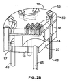
- Figure 2B illustrates a side perspective view of a cut-out section of a portion of the EO pump 10 of Figure 1 .
- Figure 2B illustrates the relation between the various components.
- Figure 2B further illustrates a series of fasteners 59 distributed about the perimeter of the side wall 22.
- the fasteners 59 hold the upper and lower plates 18 and 20 together with the porous core medium 14 and the liquid impermeable, gas permeable membrane 56 sandwiched there between.
- the gas outlets 50 are illustrated as a pattern of vents.
- upper and lower plates 18 and 20 can be adhered or bonded to side wall 22.
- the EO pumps set forth herein can be manufactured using a variety of methods.
- the various plates and walls of an EO pump chamber can be molded as a single material.
- all or some portion of the pump housing can be injection molded and in some embodiments the porous material can be provided as in insert in the mold.
- EO pumps can also be manufactured from acrylic components which can be joined by fusion bonding which uses heat and pressure to create a molecular bond between the materials without the addition of adhesive. Ultra-sonic welding is another method for joining plastic parts such as those useful in EO pumps.
- silicone gasket material can be used at interfaces between parts. Silicone can be particularly useful because it bonds well to glass.
- an adhesive can be used to bond a silicone gasket and the silicone gasket can in turn bond to a porous core medium. Such a manufacturing process provides the advantage of avoiding adhesives which can wick into the core porous material under some conditions.
- FIG. 3 illustrates an EO pump 110 formed in accordance with an alternative embodiment.
- the EO pump 110 includes a housing 112, a porous core medium 114, and electrodes 116 and 117.
- the housing 112 is constructed with a lower plate 120 and a side wall 122 that rests on the lower plate 120.
- the lower plate 120 and the side wall 122 define an interior pump cavity 128.
- the porous core medium 114 is positioned within the pump cavity 128 and oriented in an upright configuration along longitudinal axis 142 relative to gravity.
- the porous core medium 114 has an interior surface 132 and an exterior surface 134 formed concentric with one another.
- the interior surface 132 of the porous core medium 114 surrounds an open interior reservoir 136 that is open at opposite ends 138 and 140 which are spaced apart from one another along the longitudinal axis 142.
- the electrodes 116 and 117 are located in the interior and exterior reservoirs 136 and 130.
- the housing 112 has at least one fluid inlet 146 and at least one fluid outlet 148.
- the housing 112 includes an open top which forms a gas outlet 150 that extends across an entire upper area spanning the interior reservoir 136, the porous core medium 114 and the exterior reservoir 130.
- the open top gas outlet 150 receives a gas permeable, liquid impermeable membrane 156.
- a particularly useful gas permeable, liquid impermeable medium is modified PTFE.
- Gas permeable, liquid impermeable membrane can be made from any of a variety of micro structure materials having hydrophobic coatings.
- coated materials include, for example, those coated with PTFE using methods such as hot filament chemical vapor deposition (HFCVD) as described, for example, in US 5,888,591 and US 6,156,435 .
- HFCVD hot filament chemical vapor deposition
- the membrane 156 may be formed from different ePTFE membranes such as used in protective vent products offered by W.L. Gore & Associates.
- the membrane 156 may be a soft semi-permeable membrane that is adhered (e.g. glued) to the top of the housing 112. The membrane 156 is not covered by an upper plate (as in Figure 1 ).
- the side wall 122 may include an extension portion 121 to extend a distance beyond the end 138 of the porous core medium 114 to form a pocket above the porous core medium 114 and within the side wall 122.
- the membrane 156 may then fit within the pocket and be exposed to ambient air.
- the side walls 122 may terminate at a height equal to the height of the porous core medium 114, and the membrane 156 may span across and cover the upper edge of the side wall 122.
- the EO pump 110 may comprise one or more motion sources 158 that are provided on the housing 112.
- the motion source 158 may be mounted against the lower plate 120 to induce motion throughout the entire housing 112 when the motion source 158 vibrates to actively cause gas bubbles to detach from the porous core medium 114, side wall 122 and/or electrodes 116 and 117.
- the motion source 158 may represent an ultrasound source, a piezo actuator and/or electromagnet source.
- the motion source 158 may be directly coupled to, and electrically insulated from, the housing 112. Alternatively, the motion source 158 may be located proximate to the side wall 122.
- a magnetic material that is attached to the pump or that forms part of a pump component can be induced to move due to proximity to a generator of electromagnetic forces such as a wire coil with an electric current running through.
- the motion sources 158 may be continuously or periodically activated to introduce continuous or periodic energy configured to induce detachment of gas bubbles from surfaces of the EO pump 110.
- the EO pump 110 comprises a filter membrane layer 115 positioned between the interior surface 132 and electrode 116, and a filter or membrane layer 119 positioned between the exterior surface 134 and electrode 117.
- the membrane layers 115 and 119 are formed of an electrically conductive porous material that facilitates conduction of the electrical charge between the electrodes 116 and 117 and the porous core medium 114.
- the membrane layers 115 and 119 are formed of a hydrophilic material to encourage migration of the gas bubbles toward the gas outlet 150.
- the membrane layers 115 and 119 could be formed of electrically insulating materials.
- FIG 4 illustrates a configuration of electrodes 216 and 217 formed in accordance with an embodiment.
- the electrode 217 is shown in solid lines, while electrode 216 is shown in dashed lines.
- the electrode 217 is located in the exterior reservoir proximate to an exterior surface of the porous core medium 214, while the electrode 216 is located in the interior reservoir proximate to an interior surface of the porous core medium.
- the porous core medium 214 is mounted on a lower plate 220 similar to the arrangement discussed above in connection with Figure 1 .
- the electrode 217 includes a continuous body portion 215 with a helical or spring shape that extends along a spiral path about the exterior surface of the porous core medium 214.
- the body portion 215 is joined to a tail 213 formed at the base of the body portion 215.
- the tail 213 extends through the lower plate 220.
- the electrode 216 also includes a continuous body portion 211 with a helical or spring shape that extends along a spiral path proximate to the interior surface of the porous core medium 214.
- the body portion 211 is joined to a tail 209 formed at the base of the body portion 211.
- the tail 209 extends downward from the interior reservoir through the lower plate 220.
- the tails 213 and 209 are electrically coupled to a power source 207 that induces a voltage potential across the electrodes 216 and 217.
- the tails 213 and 209 may terminate on the upper surface of the lower plate 220 and be coupled to electrical contacts that are joined to the power source 207.
- the electrodes 216 and 217 may continue from the lower plate 220 upward to a point immediately adjacent the open end 238 of the porous core medium 214.
- one or both of the body portions 211 and 215 may not extend to the open end 238, but instead terminate below or short of the open end 238.
- the body portions 215 and 211 may spiral in the same or opposite directions.
- one of the body portions 211 and 215 may not be a spiral shape, while the other of the body portion 215 and 211 remains a spiral shape.
- the electrodes 216 and 217 may be placed against or immediately adjacent, the top semi-permeable membrane (e.g. medium 56 in Figure 1 or membrane 156 in Figure 3 ) in order that gases may escape directly as the gases are formed.
- FIG 5 illustrates a configuration of electrodes 316 and 317 formed in accordance with an alternative embodiment.
- the porous core medium 314 is mounted on a lower plate 320 similar to the configuration discussed above in connection with Figure 1 .
- the electrode 317 is shown in solid lines, while electrode 316 is shown in dashed lines.
- the electrode 317 includes a series of body segments 315 that extend parallel to one another at a common acute angle or helical path about the exterior surface of the porous core medium 314.
- the series of body segments 315 are joined to a common tail 313 formed at the base of the body segments 315.
- the tail 313 extends through the lower plate 220 and is coupled to the power source 307.
- the series of body segments 315 include outer ends that are joined by a terminating ring 319.
- the ring 319 and tails 313 maintain the body segments 315 in a desired shape that is spaced slightly apart from the exterior surface of the porous core medium 314.
- the electrode 316 also includes a series of body segments 311 that extend parallel to one another at a common acute angle or helical path about the interior surface of the porous core medium 314.
- the series of body segments 311 are joined to a common tail 309 formed at the base of the body segments 311.
- the tail 309 extends through the lower plate 320 and is joined to the power source 307.
- the series of body segments 311 may include upper ends that are free, or alternatively joined by a terminating ring (not shown).
- the electrodes may be constructed in various manners.
- one or more of the electrodes may include a pin shape, a mesh shape, a series of pins, a series of vertical straps and the like.
- the electrodes may represent an array of pins or a grid of contacts spread about the interior surface 23 ( Figure 1 ) of the sidewall 22.
- the tails for individual electrodes need not pass through the lower plate 20. Instead, the tails may extend inward laterally through the sidewall 22 and project inward through the exterior reservoir 30 to a location proximate, but not touching, the porous core medium 14.
- FIG. 6 illustrates an EO pump 410 formed in accordance with an alternative embodiment.
- the EO pump 410 includes a housing 412, a porous core medium 414, and electrodes 416 and 417.
- the housing 412 is constructed with a lower plate 420 and a side wall 422 that rests on the lower plate 420.
- the lower plate 420 and the side wall 422 define an interior pump cavity 428.
- the porous core medium 414 is positioned within the pump cavity 428 and oriented in an upright configuration along longitudinal axis 442 relative to gravity,
- the porous core medium 414 has a cone shape with a flat top and a flat bottom (e.g., frustoconical).
- the porous core medium 414 has an interior surface 432 that extends upward from the lower plate 420 at a tapered acute angle until opening at the top end 438.
- the porous core medium 414 has an exterior surface 434 that extends upward from the lower plate 420 at a tapered obtuse angle until opening at the top end 438.
- the interior and exterior surfaces 432 and 434 may extend upward at common or different angles such that the porous core medium 414 may have a nonuniform or uniform radial thickness.
- the porous core medium 414 may include a thicker base portion 405 proximate the bottom end 440 and a thinner head end portion 403 proximate the top end 438.
- the porous core medium 414 may be constructed with a uniform radial thickness along the length thereof.
- Such alterations in the thickness and shape of the porous core medium can provide advantages of improved gas management, for example, by directing bubbles to a vent membrane more efficiently than other shapes or reducing bubble formation at locations that do not allow efficient venting.
- the interior surface 432 of the porous core medium 414 surrounds an open interior reservoir 436 that is open at opposite top and bottom ends 438 and 440 which are spaced apart from one another along the longitudinal axis 442.
- the electrodes 416 and 417 are located in the interior and exterior reservoirs 436 and 430.
- the interior reservoir 436 includes an inverted conical shape having a narrow width at the top and having wider width at the bottom.
- the side wall 422 has a non-tapered contour that does not follow exterior surface 434 thereby forming an inverted conical shape within the exterior reservoir 430 having a narrow width 431 at the bottom and having a wide width 433 at the top.
- the housing 412 has at least one fluid inlet 446 and at least one fluid outlet 448.
- a gas permeable, liquid impermeable membrane 456 covers the top open end 438 of the porous core medium 414 spanning both the interior reservoir 436 and the exterior reservoir 430.
- the housing 412 also includes a cover 418 extending over the membrane 456 and joining the side wall 422.
- the cover 418 is spaced apart from the membrane 456 to form a gas collection area 459 therein.
- the cover 418 includes a gas outlet 450. Gas collects in the gas collection area 459 while/before being exhausted through the gas outlet 450.
- the electrode 416 includes a group of pin electrodes that are straight and project upward through the lower plate 420.
- the pin electrodes 416 are distributed about the interior reservoir 436 following the interior surface 432.
- the pin electrodes 416 may have different lengths. The length of each pin electrode 416 may be based upon the location of the pin electrode 416 relative to the interior surface 432.
- the electrode 417 may also include a group of pin electrodes that project inward through the side wall 422 and are bent upward along the exterior surface 434.
- the pin electrodes 417 are distributed about the exterior reservoir 430 following the exterior surface 434.
- the pin electrodes 417 may have different lengths. The length of each pin electrode 417 may be based upon the location of the pin electrode 417 relative to the exterior surface 434.
- the electrodes can be placed in direct contact with the pumping medium or the pump housing.
- FIG. 7 illustrates a side sectional view of an EO pump 70 formed in accordance with an embodiment of the present invention.
- the pump 70 comprises a housing 72 that has a vacuum cavity 74 provided therein.
- the housing 72 includes a vacuum inlet 76 that is configured to be coupled to a vacuum source 78 to induce a vacuum within the vacuum cavity 74.
- a core retention member 80 is provided within the vacuum cavity 74.
- the core retention member 80 has an inner pump chamber 82 that extends along a longitudinal axis 84.
- the core retention member 80 has a fluid inlet 86 and a fluid outlet 88 located at opposite ends thereof.
- the core retention member is made of a material that is gas permeable and fluid impermeable, such as PTFE AF.
- Other useful core retention members are those made from any of a variety of micro structure materials having hydrophobic coatings.
- Such coated materials include, for example, those coated with PTFE using methods such as hot filament chemical vapor deposition (HFCVD) as described, for example, in US 5,888,591 and US 6,156,435 .
- HFCVD hot filament chemical vapor deposition
- the vacuum source 78 may be removed entirely and EO pump 70 operated without inducing a vacuum in the cavity 74.
- a porous core medium 90 is provided within the core retention member 80.
- the porous core medium 90 is located between the fluidic inlet and fluidic outlet 86 and 88.
- the porous core medium is arranged to substantially fill the core retention member 80 in the cross sectional direction, to require all fluid to pass through the porous core medium to be conveyed from the fluid inlet 86 to the fluid outlet 88.
- the porous core medium 90 may be comprised of a porous homogeneous or nonhomogeneous material, or alternatively a collection of beads, either of which retain a surface charge and permit fluid to flow there through.
- Other exemplary materials are described, for example, in US 2006/0029851 A1 .
- a pump medium may be made from PEEK or other biocompatible polymers that are used in bioanalytical methods.
- the core retention member 80 has an elongated cylindrical shape that is open at opposite ends 96 and 97.
- the fluidic inlet and fluidic outlet 86 and 88 are located at the opposite ends 96 and 97 of the inner pump chamber 82.
- the core retention member 80 represents a tube having an outer wall formed from, for example, PTFE AF. The fluid flows along the tube within the outer wall while gas passes radially outward through the outer wall.
- Electrodes 92 and 94 are located proximate to the core retention member 80 and separated from one another, such that, when electrically charged, flow of a fluid is induced through the porous core medium 90 from the fluid inlet 86 to the fluid outlet 88.
- the electrodes 92 and 94 are separated from one another along the longitudinal axis 84.
- the electrodes 92 and 94 are constructed as ring shaped electrodes that are mounted about an exterior surface 81 of the core retention member 80.
- the electrodes 92 and 94 introduce an electrical potential difference across the porous core medium 90 that causes the fluid to flow in the direction of arrow A along the longitudinal axis through the porous core medium 90.
- a gas is generated at the electrode as the fluid flows through the porous core medium 90.
- the core retention member 80 being formed of a gas permeable material, permits the gas to dissipate radially outward along the length of the core retention member 80 away from the porous core medium 90.
- the optional vacuum source 78 introduces a vacuum within the vacuuming cavity 74 to induce migration of the gas in a radial direction transverse to the longitudinal axis of 84 away from the porous core medium 90 and outward through the core retention member 80.
- the electrodes 92 and 94 are coupled to a power source similar to the power sources discussed above in connection with Figures 1-6 .
- the EO pump 70 may include one or more motion sources at the electrodes 92 and/or 94, and/or within or about the exterior of the housing 72. The motion sources operate in the manner discussed above in connection with Figures 1-6 to induce detachment of gas bubbles from surfaces within the EO pump 70.
- pumps are described herein and shown in the figures for purposes of demonstrating how various pump elements can be made or used.
- the invention is not intended to be limited to the specific embodiments described herein. It is understood that various combinations and permutations of the components discussed above and hereafter may be implemented.
- the pumps shown in the Figures and descried herein differ in several respects, including but not limited to, the various locations of pump components such as electrodes, housings, porous core medium, and reservoirs; the various shapes of pump components such as electrodes, housings, porous core medium, and reservoirs; the optional use of motion sources; the optional presence of a top plate; the optional use of fasteners; and the optional use of hydrophilic coatings or membranes.
- pump components can be used in various combinations or may be used with different EO pump designs, whether described herein or known in the art, as will be understood by those skilled in the art in view of the teachings herein.
- the EO pumps discussed herein may be implemented in various applications including, but not limited to, biochemical analysis systems, flow cells or other microfluidic devices for the creation and/or analysis of analyte arrays, such as nucleic acid arrays.
- Embodiments described herein include systems, flow cells, and manifolds (or other microfluidic devices) that may be used for the creation and/or analysis of analyte arrays, such as nucleic acid arrays.
- embodiments of the arrays are formed by creating nucleic acid clusters through nucleic acid amplification on solid surfaces. Some embodiments may include several subsystems that interact with each other to create, read, and analyze the arrays.
- the subsystems may include a fluid flow subsystem, temperature control subsystem, light and reader subsystem, a moving stage which may hold the flow cells and manifolds, and a computing subsystem that may operate the other subsystems and perform analysis of the readings.
- some of the systems and devices may be integrated with or include electroosmotic (EO) pumps.
- EO electroosmotic
- the systems and devices include various combinations of optical, mechanical, fluidic, thermal, electrical, and computing aspects/features. Although portions of these are described herein, these aspects/features may be more fully described in international patent application no. PCT/US2007/007991 (published as WO 2007/123744 ), which claims priority to U.S. provisional application nos.
- a flow cell may have one or more fluidic channels in which a chemical analyte, such as a biochemical substance, is detected (e.g., wherein the chemical analytes are polynucleotides that are directly attached to the flow cell or wherein the chemical analytes are polynucleotides that are attached to one or more beads or other substrates arrayed upon the flow cell) and may be fabricated from glass, silicon, plastic, or combinations thereof or other suitable materials.
- a chemical analyte such as a biochemical substance
- a chemical analyte that is to be detected is displayed on the surface of a flow cell, for example via attachment of the analyte to the surface by covalent or non-covalent boding.
- Other analytes that can be detected using the apparatus or methods described herein include libraries of proteins, peptides, saccharides, biologically active molecules, synthetic molecules or the like.
- the apparatus and methods are exemplified below in the context of nucleic acid sequencing. However, it should be understood that other applications include use of these other analytes, for example, to evaluate RNA expression, genotyping, proteomics, small molecule library synthesis, or the like.
- a flow cell may include a combination of two or more flow cells, and the like.
- polynucleotide or “nucleic acids” refer to deoxyribonucleic acid (DNA), ribonucleic acid (RNA), or analogs of either DNA or RNA made from nucleotide analogs.
- RNA ribonucleic acid
- the terms as used herein also encompasses cDNA, that is complementary, or copy, DNA produced from an RNA template, for example by the action of reverse transcriptase.
- the nucleic acid to be analyzed, for example by sequencing, through use of the described systems is immobilized upon a substrate (e.g., a substrate within a flow cell or one or more beads upon a substrate such as a flow cell, etc.).
- a substrate e.g., a substrate within a flow cell or one or more beads upon a substrate such as a flow cell, etc.
- immobilized as used herein is intended to encompass direct or indirect, covalent or non-covalent attachment, unless indicated otherwise, either explicitly or by context.
- the analytes e.g. nucleic acids
- solid support refers to any inert substrate or matrix to which nucleic acids can be attached, such as for example glass surfaces, plastic surfaces, latex, dextran, polystyrene surfaces, polypropylene surfaces, polyacrylamide gels, gold surfaces, and silicon wafers.
- the solid support may be a glass surface (e.g., a planar surface of a flow cell channel).
- the solid support may comprise an inert substrate or matrix which has been "functionalized,” such as by applying a layer or coating of an intermediate material comprising reactive groups which permit covalent attachment to molecules such as polynucleotides.
- such supports can include polyacrylamide hydrogels supported on an inert substrate such as glass.
- the molecules can be directly covalently attached to the intermediate material (e.g. the hydrogel) but the intermediate material can itself be non-covalently attached to the substrate or matrix (e.g. the glass substrate).
- the support can include a plurality of particles or beads each having a different attached analyte.
- the systems described herein may be used for sequencing-by-synthesis (SBS).
- SBS sequencing-by-synthesis
- four fluorescently labeled modified nucleotides are used to sequence dense clusters of amplified DNA (possibly millions of clusters) present on the surface of a substrate (e.g., a flow cell).
- the flow cells containing the nucleic acid samples for sequencing can take the form of arrays of discrete, separately detectable single molecules, arrays of features (or clusters) containing homogeneous populations of particular molecular species, such as amplified nucleic acids having a common sequence, or arrays where the features are beads comprising molecules of nucleic acid.
- the nucleic acids can be prepared such that the nucleic acids include an oligonucleotide primer adjacent to an unknown target sequence.
- one or more differently labeled nucleotides, and DNA polymerase, etc. can be flowed into/through the flow cell by a fluid flow subsystem. Either a single nucleotide can be added at a time, or the nucleotides used in the sequencing procedure can be specially designed to possess a reversible termination property, thus allowing each cycle of the sequencing reaction to occur simultaneously in the presence of all four labeled nucleotides (A, C, T, G).
- the polymerase is able to select the correct base to incorporate and each sequence is extended by a single base.
- the natural competition between all four alternatives leads to higher accuracy than wherein only one nucleotide is present in the reaction mixture (where most of the sequences are therefore not exposed to the correct nucleotide).
- Sequences where a particular base is repeated one after another are addressed like any other sequence and with high accuracy.
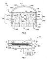
- FIG 8 illustrates a detector system 1150 that utilizes an electroosmotic (EO) pump formed in accordance with one embodiment.
- the system 1150 may include a fluid flow subsystem 1100 for directing the flow of reagents (e.g., fluorescent nucleotides, buffers, enzymes, cleavage reagents, etc.) or other solutions to and through a flow cell 1110 and waste valve 1120.
- reagents e.g., fluorescent nucleotides, buffers, enzymes, cleavage reagents, etc.
- the fluid flow system 1100 and the flow cell 1110 may include EO pumps.
- the flow cell 1110 may have clusters of nucleic acid sequences (e.g., of about 200-1000 bases in length) to be sequenced which are optionally attached to the substrate of the flow cell 1110, as well as optionally other components.
- the flow cell 1110 may also include an array of beads, where each bead optionally contains multiple copies of a single sequence.
- the system 1150 may also include a temperature control subsystem 1135 to regulate the reaction conditions within the flow cell channels and reagent storage areas/containers (and optionally the camera, optics, and/or other components).
- a heating/cooling element which may be part of the temperature control subsystem 1135, is positioned underneath the flow cell 1110 in order to heat/cool the flow cell 1110 during operation of the system 1150.
- An optional movable stage 1170 upon which the flow cell 1110 is placed allows the flow cell to be brought into proper orientation for laser (or other light 1101) excitation of the substrate and optionally moved in relation to a lens 1142 and camera system 1140 to allow reading of different areas of the substrate. Additionally, other components of the system are also optionally movable/adjustable (e.g., the camera, the lens objective, the heater/cooler, etc.).
- the flow cell 1110 is monitored, and sequencing is tracked, by camera system 1140 (e.g., a CCD camera) which can interact with various filters within a filter switching assembly (not shown), lens 1142, and focusing laser/focusing laser assembly (not shown).
- a laser device 1160 e.g., an excitation laser within an assembly optionally comprising multiple lasers
- fiber optic 1161 which can optionally include one or more re-imaging lenses, a fiber optic mounting, etc.
- Figure 9 illustrates a reader subsystem with a flow cell 1300 that may be used with an imaging or sequencing system, such as the detector system 1150 described above in Figure 8 .
- a laser coupled through optical fiber 1320 may be positioned to illuminate the flow cell 1300.
- An objective lens component 1310 may be positioned above the flow cell 1300 and capture and monitor the various fluorescent emissions once the fluorophores are illuminated by a laser or other light.
- the reagents may be directed through the flow cell 1300 through one or more tubes 1330 which connect to the appropriate reagent storage, etc.
- the flow cell 1300 may be placed within a flow cell holder 1340, which may be placed upon movable staging area 1350.
- the flow cell holder 1340 may hold the flow cell 1300 securely in the proper position or orientation in relation to the laser, the prism (not shown), which directs laser illumination onto the imaging surface, and the camera system, while the sequencing occurs.
- the objective lens component 1310 is positioned below the flow cell 1300.
- the laser may be similarly positioned as shown in Figure 9 or may be adjusted accordingly for the objective lens component 1310 to read the fluorescent emissions.
- the flow cell 1300 may be viewable from both sides (i.e., top and bottom). As such, the multiple readers or imaging systems may be used to read signals emanating from the channels of the flow cells 1300.
- FIGS 10A and 10B display a flow cell 1400 formed in accordance with one embodiment.
- the flow cell 1400 includes a bottom or base layer 1410 (e.g., of borosilicate glass 1000 ⁇ m in depth), a channel spacer or layer 1420 (e.g., of etched silicon 100 ⁇ m in depth) overlaying the base layer 1410, and a cover layer 1430 (e.g., 300 ⁇ m in depth).
- the layers 1310, 1420, and 1430 form enclosed channels 3X412 having inlets and outlets ports 1414 and 1416, respectively, at either end through the cover layer 1430.
- the flow cell 1400 may be configured to engage or sealably mate with a manifold, such as manifold 810 (in Figure 15 ).
- a manifold such as manifold 810 (in Figure 15 ).
- the inlets 1414 and outlets 1416 of the flow cell 1400 may open at the bottom of or on the sides of the flow cell 1400.
- the flow cell 1400 includes eight (8) channels 1412, alternative embodiments may include other numbers.
- the flow cell 1400 may include only one (1) channel 1412 or possibly two (2), three (3), four (4), sixteen (16) or more channels 1412.
- the channel layer 1420 may be constructed using standard photolithographic methods.
- One such method includes exposing a 100 ⁇ m layer of silicon and etching away the exposed channel using Deep Reactive Ion Etching or wet etching.
- the channels 1412 may have different depths and/or widths (different both between channels in different flow cells and different between channels within the same flow cell).
- the channels 1412 formed in the cell in Figure 10B are 100 ⁇ m deep, other embodiments can optionally comprise channels of greater depth (e.g., 500 ⁇ m) or lesser depth (e.g., 50 ⁇ m).
- FIGS 10C and 10D illustrate flow cell configurations formed in accordance with alternative embodiments.
- flow cells 1435 may have channels 1440, which are wider than the channels 1412 described with reference to the flow cell 1400, or two channels having a total of eight (8) inlet 1445 and outlet ports 1447.
- the flow cell 1435 may include a center wall 1450 for added structural support.
- the flow cell 1475 may include offset channels 1480 such that the inlet 1485 and outlet ports 1490, respectively, are arranged in staggered rows at opposite ends of the flow cell 1475.
- the flow cells may be formed or constructed from a number of possible materials.
- the flow cells may be manufactured from photosensitive glass(es) such as Foturan® (Mikroglas, Mainz, Germany) or Fotoform® (Hoya, Tokyo, Japan), which may be formed and manipulated as necessary.
- Other possible materials can include plastics such as cyclic olefin copolymers (e.g., Topas® (Ticona, Florence, KY) or Zeonor® (Zeon Chemicals, Louisville, KY)) which have excellent optical properties and can withstand elevated temperatures.
- the flow cells may be made from a number of different materials within the same flow cell.
- the base layer, the walls of the channels, and the cover layer can optionally be of different materials.
- the example in Figure 10B shows a flow cell 1400 formed of three (3) layers
- other embodiments can include two (2) layers, e.g., a base layer having channels etched/ablated/formed within it and a cover layer, etc.
- Other embodiments can include flow cells having only one layer which comprises the flow channel etched/ablated/otherwise formed within it.
- Figure 11 gives a schematic diagram of a process for patterning a flow cell in accordance with one embodiment.
- the desired pattern is masked out with masks 500, onto the surface of substrate 510 which is then exposed to UV light.
- the glass is exposed to UV light at a wavelength between 290 and 330 nm.
- silver or other doped atoms are coalesced in the illuminated areas (areas 520).
- the glass crystallizes around the silver atoms in area 520.
- the crystalline regions when etched with a 10% hydrofluoric acid solution at room temperature (anisotropic etching), have an etching rate up to 20 times higher than that of the vitreous regions, thus resulting in channels 530. If wet chemical etching is supported by ultrasonic etching or by spray- etching, the resulting structures display a large aspect ratio.
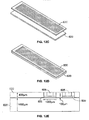
- Figures 12A-E show an etching process that may be used to construct a flow cell in accordance with one embodiment.
- Figure 12A illustrates an end view of a two-layer flow cell that includes channels 600 and through-holes 605.
- the channels 600 and through-holes 605 are exposed/etched into a cover layer 630.
- the cover layer 630 mates with a bottom layer 620 (shown in Figure 12E ).
- the through-holes 605 are configured to allow reagents/fluids to enter into the channels 600.
- the channels 600 can be etched into layer 630 through a 3-D process such as those available from Invenios (Santa Barbara, CA).
- the cover layer 630 may include Foturan and may be UV etched.
- FIG. 12B the cover layer 630 has been masked and light exposed to produce optically opaque areas 610 within the layer.
- the optically opaque areas may facilitate blocking misdirected light, light scatter, or other nondesirable reflections that could otherwise negatively affect the quality of sequence reading.
- a thin (e.g., 100-500 nm) layer of metal such as chrome or nickel is optionally deposited between the layers of the flow cell (e.g., between the cover and bottom layers in Figure 12E ) to help block unwanted light scattering.
- Figures 12C and 12D display the mating of bottom layer 620 with cover layer 630 and Figure 12E shows a cut away view of the same.
- the layers of the flow cells may be attached to one another in a number of different ways.
- the layers can be attached via adhesives, bonding (e.g., heat, chemical, etc.), and/or mechanical methods.
- bonding e.g., heat, chemical, etc.
- Those skilled in the art will be familiar with numerous methods and techniques to attach various glass/plastic/silicon layers to one another.
- Other flow cells can include different materials and designs than those presented herein and/or can be created through different etching/ablation techniques or other creation methods than those disclosed herein.
- particular flow cell compositions or construction methods should not necessarily be taken as limiting on all embodiments.
- the reagents, buffers, and other materials that may be used in sequencing are regulated and dispensed via the fluid flow subsystem 100 ( Figure 1 ).
- the fluid flow subsystem 100 transports the appropriate reagents (e.g., enzymes, buffers, dyes, nucleotides, etc.) at the appropriate rate and optionally at the appropriate temperature, from reagent storage areas (e.g., bottles, or other storage containers) through the flow cell 110 and optionally to a waste receiving area.
- the fluid flow subsystem 100 may be computer controlled and can optionally control the temperature of the various reagent components.
- certain components are optionally held at cooled temperatures such as 4°C +/- 1°C (e.g., for enzyme containing solutions), while other reagents are optionally held at elevated temperatures (e.g., buffers to be flowed through the flow cell when a particular enzymatic reaction is occurring at the elevated temperature).
- cooled temperatures such as 4°C +/- 1°C
- elevated temperatures e.g., buffers to be flowed through the flow cell when a particular enzymatic reaction is occurring at the elevated temperature
- various solutions are optionally mixed prior to flow through the flow cell 1110 (e.g., a concentrated buffer mixed with a diluent, appropriate nucleotides, etc.). Such mixing and regulation is also optionally controlled by the fluid flow subsystem 1100. Furthermore, it may be advantageous to minimize the distance between the components of the system 1150. There may be a 1:1 relationship between pumps and flow channels, or the flow channels may bifurcate into two or more channels and/or be combined into one or more channel at various parts of the fluid subsystem.
- the fluidic reagents may be stored in reagent containers (e.g., buffers at room temperature, 5X SSC buffer, enzymology buffer, water, cleavage buffer, cooled containers for enzymes, enzyme mixes, water, scanning mix, etc.) that are all connected to the fluid flow subsystem 1100.
- reagent containers e.g., buffers at room temperature, 5X SSC buffer, enzymology buffer, water, cleavage buffer, cooled containers for enzymes, enzyme mixes, water, scanning mix, etc.
- Multi-way valves may also be used to allow controllable access of/to multiple lines/containers.
- a priming pump may be used to draw reagents from the containers up through the tubing so that the reagents are "ready to go” into the flow cell 1110. Thus, dead air, reagents at the wrong temperature (e.g., because of sitting in tubing), etc. may be avoided.
- the fluid flow itself is optionally driven by any of a number of pump types, (e.g., positive/negative displacement, vacuum, peristaltic, and electroosmotic, etc.).
- the reagents are optionally transported from their storage areas to the flow cell 1110 through tubing.
- tubing such as PTFE
- the diameter of the tubing can vary between embodiments (and/or optionally between different reagent storage areas), but can be chosen based on, e.g., the desire to decrease "dead volume" or the amount of fluid left in the lines
- the size of the tubing can optionally vary from one area of a flow path to another.
- the tube size from a reagent storage area can be of a different diameter than the size of the tube from the pump to the flow cell, etc.
- the fluid flow system 1100 can be further equipped with pressure sensors that automatically detect and report features of the fluidic performance of the system, such as leaks, blockages and flow volumes. Such pressure or flow sensors can be useful in instrument maintenance and troubleshooting.
- the fluidic system can be controlled by the one or more computer component, e.g., as described below. It will be appreciated that the fluid flow configurations in the various embodiments can vary, e.g., in terms of number of reagent containers, tubing length, diameter, and composition, types of selector valves and pumps, etc.
- the various components of the system 1150 may be coupled to a processor or computing system that functions to instruct the operation of these instruments in accordance with preprogrammed or user input instructions, receive data and information from these instruments, and interpret, manipulate and report this information to the user.
- the computing system is typically appropriately coupled to these instruments/components (e.g., including an analog to digital or digital to analog converter as needed).
- the computing system may include appropriate software for receiving user instructions, either in the form of user input into set parameter fields, e.g., in a GUI, or in the form of preprogrammed instructions, e.g., preprogrammed for a variety of different specific operations (e.g., auto focusing, SBS sequencing, etc.).
- the software may then convert these instructions to appropriate language for instructing the correct operation to carry out the desired operation (e.g., of fluid direction and transport, autofocusing, etc.).
- the data e.g., light emission profiles from the nucleic acid arrays, or other data, gathered from the system can be outputted in printed form.
- the data whether in printed form or electronic form (e.g., as displayed on a monitor), can be in various or multiple formats, e.g., curves, histograms, numeric series, tables, graphs and the like.
- Figures 13 and 14 illustrate a flow cell 700 that may be constructed to receive EO pumps in accordance with one embodiment.
- Figure 13 is a planar view of the flow cell 700
- Figure 14 is a cross-sectional view of an end portion of the flow cell 700.
- the flow cell 700 includes a flow cell body 702 that may be formed from one or more substrate layers stacked upon each other.
- the flow cell body 702 includes a bottom layer 704, a channel spacer or layer 706, and a cover layer 708.
- the channel spacer 706 may be optically opaque in order to block misdirected light, light scatter, or other nondesirable reflections that could otherwise negatively affect the quality of sequence reading.
- the flow cell body 702 has a substantially planar bottom surface 720 ( Figure 14 ) and a substantially planar top surface 722.
- the surfaces 720 and 722 may be transparent allowing light to pass therethrough, and either surface 720 or 722 (and corresponding layers 704 and 708, respectively) may be configured to be held by the system 1150 or, more specifically, the holder subassembly 800 (shown in Figure 15 ).
- the bottom layer 704 may have drilled holes or indentations for the holder 806 and/or prism 804 (both shown in Figure 15 ) to engage.
- the layers 704, 706, and 708 are configured to form one or more channels 712 that extend between and are in flow communication with a fluidic inlet/outlet (I/O) port 714 at one end 697 ( Figure 13 ) of the flow cell body 702 and another fluidic inlet/outlet (I/O) port 716 ( Figure 14 ) at the other end 699.
- the flow cell body 702 may include one or more pump cavities 724, each of which is interposed between one end 699 of the channel 712 and one of the fluidic I/O ports 716.
- the pump cavity 724 is shaped to hold one or more electroosmotic (EO) pumps 730, which will be described in further detail below.
- EO electroosmotic
- the pump cavities 724 are joined to fluid channels 712 and to gas discharge channels 713.
- the gas discharge channels 713 extend to a common area, such as side 698 or to end 699 of the flow cell body 702.
- the gas discharge channels 713 terminate at gas ports 717 that are coupled to a gas removal device (e.g. 52 in Figure 1 ) or a vacuum source (e.g. 78 in Figure 7 ).
- the gas ports 717 may align with mating ports in the holder assembly 800.
- the pump cavities 724 may be joined to a common gas discharge channel 713 with a common gas port 717, thereby simplifying the gas coupling path to/from the flow cell body 702.
- the pump cavity 724 receives an EO pump 10 ( Figure 1 ) or any other EO pump described in or consistent with the inventions described in the present application.
- the EO pump 10 within Figure 14 will be described with the reference numerals discussed above in connection with Figure 1 .
- the EO pump 10 includes side walls 22, a porous core medium 14, upper and lower plates 18 and 20, a membrane 56 that is gas permeable but liquid impermeable, electrodes 16 and 17, fluid inlet 46 and fluid outlets 48 and gas outlets 50.
- the electrodes 16 and 17 terminate at contacts 19 and 21 on the lower plate 20 to facilitate an electrical connection of the EO pump 10 once inserted into the flow cell body 702.
- the contacts 19 and 21 join to mating contacts within the flow cell body 702.
- the fluid inlet 46 aligns with the inlet port 716, while the fluid outlets 48 align with ports coupled with the fluid channel 715.
- a fluid passage 748 is joined to each of the fluid outlets 48 and extends from the bottom plate 20 of the EO pump 10 up to the fluid channel 715.
- the gas outlets 50 receive gas that passes through the membrane 56.
- the gas outlets 50 discharge the gas into a gas channel 713 that runs along the top of the cover plate 18.
- the EO pump 10 may be constructed to omit the side walls 22 entirely and utilize the walls of the pump cavity 724 to define the exterior surface of the exterior reservoir.
- the electrodes 16 and 17 may be electrically charged by a power source (not shown).
- the power source may be a battery, AC power supply, DC power supply, or any other source.
- the electrode 16 is positively charged and operates as an anode.
- the electrode 17 is negatively charged and operates as a cathode.
- surfaces of the pump cavity 724 may be coated in an insulating material to prevent current leakage.
- the insulating material may be, for example, silicon dioxide, silicon nitride, or multiple layers of these materials.
- the charge may be created by inductive coupling rather than a direct electrical connection.
- the contacts 16 and 17 may be replaced with inductive contacts.
- the inductive contacts may be embedded below the upper and/or lower surfaces of the top and bottom layers of the flow cell.
- the inductive contacts may be covered in insulation to avoid direct exposure to surrounding environment.
- the flow cell holder would include transformer sources proximate the areas on the flow cell where the inductive contacts are to be positioned. Once the flow cell is placed in the holder, the transformer sources would create local electromagnetic fields in the areas surrounding the inductive contacts. The EM fields would induce current flow at the inductive contacts, thereby creating a voltage potential between the inductive contacts.
- the components of the EO pump 10 described above may be fastened or sealed together such that the components of the EO pump 10 form an integrated unit.
- the components may be affixed within an acrylic housing.
- the flow cell 700 may be configured to allow the EO pump 10 to be replaced by another EO pump unit when the EO pump 10 fails or another EO pump with different properties is desired.
- the bottom flow cells may be held to the flow cell holder through vacuum chucking rather than clamps.
- a vacuum can hold the flow cell into the correct position within the device so that proper illumination and imaging can take place.
- the flow cell 700 illustrates a "push" flow cell in that the EO pump 10 is positioned upstream from the channel 712 ( Figure 14 ) and forces the fluid into the channels 712 via the connecting passage 715 where the reactions may occur.
- the EO pump 10 is a "pull" flow cell in that the EO pump 10 is placed downstream from the channel 712 (i.e., after the reactions have occurred) such that the EO pump 10 draws the solution or fluid through the channel 712 before the fluid enters the pump.
- the EO pump 10 may either push or pull the fluids of interest directly, or alternatively, the EO pump 10 may utilize a working fluid (e.g. de-ionized water), which subsequently generates a pressure gradient upon the fluids of interest.
- a working fluid may be suitable when the fluid of interest is of a high ionic strength (e.g. Sodium Hydroxide) which would lead to higher currents, and therefore more gas generation.
- Figure 15 is a perspective view of a holder subassembly 800 that may be formed in accordance with one embodiment.
- the subassembly 800 is configured to hold flow cells 802 while the reader system (not shown) takes readings.
- the flow cells 802 may be similar to the flow cells 700 discussed above or may not include EO pumps.
- the subassembly 800 includes a holder 806 that is configured to support one or more inlet manifolds 808, prisms 804, flow cells 802, and outlet manifolds 810. As shown, each flow cell 802 is in flow communication with one inlet manifold 808 and one outlet manifold 810.
- a line 812 may provide the working fluid to the inlet manifold 808 in which an inner passageway (not shown) bifurcates and delivers the fluid to each of the channels on the flow cells 802.
- the holder 806 may have the prisms 804 fastened thereto by using, for example, screws. Each prism 804 is configured to hold one of the flow cells 802 and is configured to facilitate the reading process by refracting and/or reflecting the light that is generated by, for example, a laser.
- the subassembly 800 may also include a suction device/vacuum chuck positioned under each flow cell 802 that creates a vacuum (or partial vacuum) for holding the corresponding flow cell 802 and/or corresponding prism 804 to the holder 806.
- the vacuum chuck may include a heating device or thermally conductive rim/member that contacts the flow cell and regulates the temperature of the flow cell in addition to holding the flow cell or prism in position.
- a line 814 may, for example, be connected to a vacuum for providing the negative pressure to hold the flow cells 802 against the corresponding prisms 804.
- the manifolds 810 may be configured to receive EO pumps 811 therein.
- the EO pumps 811 may be provided in addition to, or in place of, the EO pumps in the flow cells 802.
- a group of EO pumps 811 are illustrated in Figure 15 in cut-away portions of the manifolds 810. In the example of Figure 15 , eight channels are provided in each flow cell 802 and thus eight EO pumps 811 are provided within each manifold 810.
- more or view EO pumps may be provided.
- a common EO pump may be utilized to pull fluid through multiple channels.
- Figure 16 is an exploded perspective view of the components used to form the outlet manifold 810 with a portion of the manifold shown in cut-away form.
- the manifold 810 includes a housing that may be formed from upper and lower layers 820 and 822.
- the layer 820 includes a channel connector 824 that extends from a base 826.
- the channel connector 824 includes one or more passages 825 that are configured to couple with the channels in the flow cell 802.
- the layer 820 also includes a lateral surface 832.
- the passages 825 extend a vertical distance H through the connector 824 and the base 826 to the lateral surface 832.
- the base 826 extends laterally outward from a body 828.
- the body 828 includes one or more EO pump cavities 830 that are in flow communication with passages 834.
- the pump cavities 830 have access openings in the surface 832 for allowing EO pumps to be inserted therein.
- the EO pumps may be inserted in the direction of arrow A up through the bottom of the layer 820.
- the layer 822 includes a base 836 that extends laterally outward from a body 838.
- the base 836 and body 838 share a top lateral surface 842 that has one or more channel grooves 846 formed therein.
- the channel grooves 846 form a flared pattern. Mating channel grooves may be provided in the bottom surface 832 of layer 820.
- the layer 822 also includes a plurality of pump cavities 844, where each pump cavity 844 has an access opening 831 to allow one of the EO pumps to be inserted.
- the layers 820 and 822 are secured together. For example, an epoxy may be applied to the lateral surfaces 832 and 842 which may then be thermally bonded together.
- a first subset of the EO pumps may be held in the upper layer 820 and a second subset of the EO pumps may be held in the lower layer 822.
- all of the EO pumps may be located in one of layers 820 and 822, or the EO pumps may extend into both layers 820 and 822 and be sandwiched there between.
- FIGS 26 and 27 illustrate top and bottom perspective views, respectively, of an electroosmotic (EO) pump 1610 formed in accordance with an embodiment of the present invention.
- the pump 1610 comprises a housing 1612 including end walls 1621, side walls 1622 and a bottom 1620 that surround a pump cavity 1628.
- the housing 1612 is rectangular in shape with a length extending along longitudinal axis 1627 and a width extending along lateral axis 1625.
- the pump cavity 1628 receives a plurality of porous core mediums 1614 that are arranged in a pattern or array.
- the porous core mediums 1614 are spaced apart from one another to form a single common fluid reservoir 1630 therebetween and within the pump cavity 1628.
- the bottom 1620 of the pump cavity 1628 may be formed with a flat interior surface 1619 on which the porous core mediums 1614 are positioned.
- the interior surface 1619 of the bottom 1620 may be formed with a recessed pattern, such as an array of circular indentations, to maintain the porous core medium 1614 in fixed, spaced apart positions.
- the porous core mediums 1614 may be constructed as cylindrical frits that are placed in an upright orientation within the pump cavity 1628 along core axes 1624 (denoted by arrow 1624).
- the core axes 1624 are oriented upright relative to gravity and orthogonal to the lateral axis 1625 and longitudinal axis 1627 of the housing 1612.
- Each porous core medium 1614 has an interior surface 1632 and an exterior surface 1634 formed concentric with one another in an open cored, tubular shape.
- the interior surface 1632 of each porous core medium 1614 surrounds a corresponding central or interior reservoir 1636.
- the interior reservoir 1636 is open at opposite ends 1638 ( Figure 26 ) and 1640 ( Figure 27 ) that are spaced apart from one another along the core axis 1624.
- the porous core mediums 1614 are spaced inward from the side walls 1622 and end walls 1621 and are separated apart from one another to provide fluid flow gaps therebetween.
- the volume within the pump cavity 1628 surrounding the porous core mediums 1614 represents the common exterior reservoir 1630.
- the housing 1612 has an upper cover 1656 that is formed from a liquid impermeable, gas permeable membrane.
- the upper cover 1656 spans across the porous core mediums 1614 between the end and side walls 1621 and 1622 to entirely cover the pump cavity 1628.
- the upper cover 1656 permits gas bubbles that are generated within the pump cavity 1628 to be exhausted therefrom while retaining fluid in the pump cavity 1628.
- the upper cover 1656 also serves to separate the interior reservoir 1636 of each porous core medium 1614 from the common exterior reservoir 1630.
- a common electrode 1617 is positioned within the exterior reservoir 1630 of the pump cavity 1628.
- the electrode 1617 is shaped to extend along a curved path about the porous core mediums 1614 and throughout the pump cavity 1628.
- the common electrode 1617 includes curved sections 1615 and straight sections 1613.
- the curved sections 1615 may wrap along an arc concentric about the exterior surfaces 1634.
- the curved sections 1615 may contact or closely follow the exterior surfaces 1634 of the porous core mediums 1614, while the straight sections 1613 span the gaps between the porous core mediums 1614.
- the common electrode 1617 extends from one end wall 1621 to the other end wall 1621 and back multiple times.
- more than one common electrode 1617 may be provided within the pump cavity 1628.
- Individual core electrodes 16 are positioned in the interior reservoirs 1636 of each porous core medium 1614.
- the electrodes 1616 may be positioned against or proximate to, but spaced slightly apart from, the interior surfaces 1632 of the porous core mediums 1614.
- the electrodes are placed in such a way to maintain equal flow from each porous core medium. Alternatively, the electrode placement can be such that the flow rate can be tuned to desired values relative to each other.
- the electrodes 1616 and 1617 are supplied with opposite electrical charges by a power source. The polarity of the electrodes 1616 and 1617 is selected depending upon a desired direction of fluid flow.
- the electrodes 1616 may constitute anodes, while the electrode 1617 constitutes a cathode to achieve radial outward flow from the interior reservoirs 1636 to the common exterior reservoir 1630.
- the electrode 1617 may constitute the anode, while the electrodes 1616 constitute cathodes to achieve radial inward flow.
- the electrodes 1616 and 1617 and the porous core mediums 1614 cooperate to induce flow of the fluid through the porous core mediums 1614 between the individual interior and common exterior reservoirs 1636 and 1630. The direction of flow is dependent upon the charges applied to the electrodes 1616 and 1617.
- the housing 1612 has at least one fluid inlet 1646 that communicates with each interior reservoir 1632 and at least one fluid outlet 1648 for the common exterior reservoir 1630.
- the bottom 1620 may include a separate fluid inlet 1646 within each of the open ends 1640, and a single fluid outlet 1648 in side wall 1622.
- the fluid inlets 46 convey fluid into the interior reservoir 1636.
- the fluid outlet 1648 discharges the fluid from the exterior reservoir 1630 once the fluid is pumped through the porous core medium 1614.
- the flow direction of the fluid inlets 1646 and fluid outlets 1648 maybe reversed such that fluid flows from the exterior reservoir 1630 radially inward to the interior reservoirs 1636.
- the upper cover 1656 allows gas to be discharged from the top of the housing 1612. The gas migrates toward the upper cover 1656 along a direction transverse (e.g. along core axis 1624) to the radial direction of fluid flow through the porous core mediums 1614.
- the housing 1612 and/or pump cavity 1628 may have a square, triangular, oval, hexagonal, polygonal shape and the like, when viewed from the top and/or side.
- the cylindrical porous core medium 1614 acts as a flow and current barrier between pumps.
- the entire upper cover 1656 of the housing 1612 is a soft top venting membrane.
- the EO pump 1610 may use a single voltage source or independently controlled sources. When multiple voltage sources are used, the EO pump 1610 share a common electrode 1617, but the potential across each porous core medium 1614 can be independently controlled by a corresponding individual voltage source. When a single voltage source is used, the electric field, and thus the flow rate, can be tuned by varying the geometry of the common electrode 1617.
- the embodiment of Figures 26 and 27 provides various advantages including, among others, a larger reservoir for gas management, ease of construction, a compact form factor, and ease of pump replacement.
- FIG 28 illustrates a side sectional view of an EO pump 1670 formed in accordance with an alternative embodiment of the present invention.
- the pump 1670 comprises a housing 1672 that has a vacuum cavity 1674 provided therein.
- a core retention member 1680 is provided within the vacuum cavity 1674.
- the core retention member 1680 has an inner pump chamber 1682 that forms a fluid channel that extends along a longitudinal axis 1684. Fluidic inlet and fluidic outlet 1686 and 1688 are located at the opposite ends 1696 and 1697 of the inner pump chamber 1682.
- the core retention member 1680 is made of a material that is gas permeable and fluid impermeable.
- the housing 1672 includes a vacuum inlet 1676 that is configured to be coupled to a vacuum source (not shown) to induce a vacuum within the vacuum cavity 1674.
- a vacuum source not shown
- the vacuum source may be removed entirely and EO pump 1670 operated without inducing a vacuum in the cavity 1674.
- a porous core medium 1690 is provided within the core retention member 1680.
- the porous core medium 1690 is located between the fluidic inlet and fluidic outlet 1686 and 1688.
- the porous core medium 1690 is arranged to substantially fill the core retention member 1680 in the cross sectional direction, to require all fluid to pass through the porous core medium 1690 to be conveyed from the fluid inlet 1686 to the fluid outlet 1688.
- the porous core medium 1690 may be comprised of a porous homogeneous or nonhomogeneous material, a collection of beads, PEEK, or other biocompatible polymers that retain a surface charge and permit fluid to flow there through.
- the core retention member 1680 has an elongated cylindrical shape that is open at opposite ends 1696 and 1697.
- the core retention member 1680 represents a tube having an outer wall formed from, for example, PTFE AF.
- the fluid flows along the tube within the outer wall, in the direction of arrow A while gas passes radially outward through the outer wall, in the direction of arrow B.
- Electrodes 1692 and 1694 extend into the core retention member 1680 and are located proximate to opposite surfaces 1691 and 1693 of the porous core medium 1690, such that, when electrically charged, flow of a fluid is induced through the porous core medium 1690 from the fluid inlet 1686 to the fluid outlet 1688.
- the electrodes 1692 and 1694 are separated from one another along the longitudinal axis 1684.
- the electrodes 1692 and 1694 introduce an electrical potential difference across the porous core medium 1690 that causes the fluid to flow in the direction of arrow C along the longitudinal axis through the porous core medium 1690.
- a gas is generated at the electrode as the fluid flows through the porous core medium 1690.
- the core retention member 1680 being formed of a gas permeable material, permits the gas to dissipate radially outward from the core retention member 1680 away from the porous core medium 1690.
- the optional vacuum source (not shown) introduces a vacuum within the vacuuming cavity 1674 to induce migration of the gas in the radial direction (as denoted by arrows D) transverse to the longitudinal axis of 1684 away from the porous core medium 1690 and outward through the core retention member 1680. Venting of the electrolysis gases can be improved using a vacuum housing (depending on the gas generation rate and tubing permeability).
- threaded fittings 1681 and 1683 may be integrated at opposite ends of the housing 1672 as a part of the existing tubing network of a slide interface and manifold.
- the fittings 1681 and 1683 may be screwed-in to lock in place opposite ends 1697 and 1696 of the core retention member 1680.
- the fittings 1681 and 1683 may be unscrewed and slid off over opposite ends 1697 and 1696 of the core retention member 1680 to replace the core retention member 1680.
- FIG 29 illustrates an end perspective view of a manifold 1601 formed in accordance with an alternative embodiment.
- the manifold 1601 includes a vacuum housing 1603 that holds a plurality of core retention members, such as core retention member 1680 ( Figure 28 ) which form separate fluid channels through the manifold 1601.
- a single inlet 1686 may be provided to supply fluid to multiple or all of the channels.
- the core retention members 1680 have inlets that communicate with the single inlet 1686 and fluid outlets 1688 at opposite ends.
- a vacuum inlet 1605 and electrode inlets 1607 are provided in the housing 1603 of the manifold 1601. In the example of Figure 29 , the electrode inlets 1607 are grouped in eight pairs, a separate pair for each of the eight core retention members 1680.
- the electrode inlets 1607 receive electrodes such as electrodes 1692 and 1694 ( Figure 28 ).
- the electrodes 1692 and 1694 may provide each channel with a unique applied electrical field.
- eight pumps may be rapidly changed and all pumps may share a common vacuum line 1605.
- the embodiment of Figure 29 provides various advantages such as a compact design, minor alterations to the existing slide interface, a large venting area, a pull and push flow capable, and compatibility with existing PEEK fitting technology.
- FIG 30 illustrates a block diagram of a pump/flow subsystem 1700 formed in accordance with one embodiment.
- the subsystem 1700 includes a flow cell 1702 that receives a fluid of interest 1720 at inlet 1704 and that discharges the fluid of interest 1720 at outlet 1706.
- the outlet 1706 is fluidly coupled to an EO pump 1708 over channel 1710.
- the EO pump 1708 includes a pump inlet 1712 and a pump outlet 1714.
- the pump outlet 1714 is coupled to a working fluid reservoir 1722 which stores a working fluid 1724.
- the working fluid 1724 is supplied over channel 1726 to the EO pump 1708.
- the working fluid 1724 fills the EO pump 1708 and passes into a first section 1728 the channel 1710 until meeting the fluid of interest 1720.
- the fluid of interest 1720 fills the second section 1730 of the channel 1710.
- the working fluid 1724 and fluid of interest 1720 come into contact with one another at a fluid to fluid interface 1732.
- the interface 1732 may simply represent a fluid interface, such as when the working fluid and the fluid of interest do not intermix due to their properties.
- the interface 1732 may represent a membrane that is permitted to move within and along the channel 1710 as the working fluid is pumped through the EO pump 1708.
- the EO pump 1708 drives the working fluid along one or both of directions 1736 and 1738 to push and/or pull the working fluid 1724 toward and/or away from the flow cell 1702.
- the working fluid 1724 forces the fluid of interest to flow in the same direction and through the flow cell 1702.
- the working fluid 1724 may be selected to have desired properties well suited for operation in EO pump 1708.
- the EO pump 1708 will operate independent of the properties of the fluid of interest 1702.
- the EO pump 1708 may either push or pull the fluid of interest.
- the working fluid may represent de-ionized water, which subsequently generates a pressure gradient upon the fluid of interest 1720.
- the working fluid 1724 may be suitable when the fluid of interest 1710 is of a high ionic strength (e.g. Sodium Hydroxide) which would lead to higher currents, and therefore more gas generation if passed through the EO pump 1708.
- a high ionic strength e.g. Sodium Hydroxide
- Figure 17 illustrates a cross-sectional view of the manifold 810 after the layers 820 and 822 have been secured together.
- one EO pump 10 is shown in cross section. It is recognized that the EO pump 10 is not to scale.
- the EO pump 10 includes the structure and reference numerals of the EO pump 10 of Figure 1 and thus is not discussed further here.
- the manifold 810 When constructed, the manifold 810 has a detector engaging end 852 and a line terminating end 854.
- the corresponding connector passages 825, channel grooves 846, and passages 834 form one channel 860 that extends from the detector engaging end 852 to the line terminating end 854.
- the line terminating end 854 includes a receptacle that is in flow communication between the pump cavity 830 ( Figure 16 ) and a discharge line 884.
- a sealing member 882 is secured to the receptacle and couples the discharge line 884 to an I/O port of the pump cavity 830.
- the manifold 810 may be fastened to the holder 806 ( Figure 15 ) using a screw hole 851.
- the connector 824 is sealably connected to the flow cell 802 ( Figure 16 ) such that each channel 860 connects to a corresponding channel in the flow cell 802.
- the EO pumps 10 may be fitted with larger components (e.g., electrodes and porous core) thereby allowing a greater flow rate.
- more EO pumps 10 may be used within the predetermined width of the manifold 810.
- Figure 18 is a cross-section of an EO pump 933 that may be used in the manifold 810, or in flow cells. As shown, the pump cavity 930 is in flow communication with the passage 934 and an I/O port 916 which leads to the discharge line.
- the EO pump 933 includes at least two electrodes 932 and 934 that are positioned a predetermined distance apart and have bodies that extend in a direction substantially parallel with respect to each other.
- the electrodes 932 and 934 may be, for example, wire coil electrodes so as to not substantially disrupt the flow of the fluid.
- the electrodes 932 and 934 may be electrically connected to contacts (not shown) which are, in turn, connected to a power source.
- the electrode 932 is positively charged and operates as an anode.
- the electrode 934 is negatively charged and operates as a cathode.
- the EO pump 933 also includes a core 940 that is interposed between the electrodes 932 and 934.
- the core 940 may be similar to the core 14 described above and includes a number of small pathways allowing the fluid to flow therethrough.
- the core 940 has a shape that extends across the pump cavity 930 such that the core 940 substantially separates the pump cavity 930 into two reservoirs 942 and 944.
- an electric potential is applied between the electrodes 932 and 934, the fluid flows through the core 940 from the reservoir 942 to the reservoir 944.
- the applied electrical potentials may lead to the generation of gases (e.g., H2 generated near the electrode 934 and 02 generated near the electrode 932).
- the gas rises toward the top of the pump cavity 930 thereby avoiding the core 940 so that the gases do not interfere with the fluid flow through the core 940. As shown, the gases may form pockets at the top of the pump cavity 930 (illustrated by the fill lines FL).
- the EO pump 933 may include a vapor permeable membrane 946, which may be fabricated from, for example, polytetrafluoroethylene (PTFE).
- the membrane 946 may be positioned above the core 940 and, in one example, may form a collar that surrounds a portion of a perimeter of the core 940.
- the membrane 946 allows the 02 gas to pass from the reservoir 942 to the reservoir 944.
- the EO pump 933 may include a catalyst member 948 within the reservoir 944.
- the catalyst member 948 operates as a catalyst for recombining the gases generated by the electrodes 932 and 934.
- the membrane 946 and catalyst member 948 may be located proximate to the core 940 in an area in which gases collect once generated during operation of the EO pump 933.
- the catalyst member 948 facilitates recombining the H2 and 02 gases into water, which may then rejoin the fluid within the reservoir 944.
- FIG 19 is a cross-sectional view of an EO pump 1233 formed in accordance with an alternative embodiment.
- the EO pump 1233 may be used or integrated with the flow cells and/or the manifolds discussed herein. Furthermore, the EO pump 1233 may be positioned upstream or downstream from corresponding channels (not show) within a flow cell (not shown).
- the EO pump 1233 is positioned within a pump cavity 1224.
- the EO pump 1233 includes at least two electrodes 1232 and 1234 that are positioned a predetermined distance apart and have bodies that extend in a direction substantially parallel with respect to each other.
- the electrodes 1232 and 1234 may be electrically connected to contacts (not shown), which are connected to a power source (not shown).
- the electrode 1232 is positively charged and operates as an anode, and the electrode 1234 is negatively charged and operates as a cathode.
- the EO pump 1233 also includes a porous core medium 1240 that is interposed between the electrodes 1232 and 1234.
- the core 1240 has a shape that surrounds the electrode 1232.
- the core 1240 may have one portion that encircles the electrode 1232 or may include two portions that have the electrode 1232 interposed there between.
- an electric potential is applied between the electrodes 1232 and 1234, the fluid flows through the core 1240 from an inner reservoir 1242 to an outer reservoir 1244.
- the applied electrical potentials may lead to the generation of gases (e.g., H2 generated near the electrode 1234 and 02 generated near the electrode 1232).
- the gas rises toward the top of the pump cavity 1224 thereby avoiding the core 1240 so that the gases do not interfere with the fluid flow through the core 1240.
- the EO pump 1233 may also include a vapor permeable membrane 1246, which may be fabricated from, for example, polytetrafluoroethylene (PTFE).
- the membrane 1246 may be positioned above the core 1240 and, in one example, may form a top that covers the core 1240.
- the membrane 1246 allows the 02 gas to pass from the reservoir 1242 to the reservoir 1244.
- the EO pump 1233 may include a catalyst member 1248 within the pump cavity 1224. Similar to the catalyst member 748 and 948, the catalyst member 1248 operates as a catalyst for recombining the gases generated by the electrodes 1232 and 1234.
- the membrane 1246 and catalyst member 1248 may be located proximate to the core 1240 and define a gas collection area 1247 therebetween where gases collect. When the gases mix in the collection area 1247, the catalyst member 1248 facilitates recombining the H2 and O2 gases into water, which may then rejoin the fluid within the reservoir 1244.
- the membrane 1246 is positioned below the catalyst member 1248 such that when the gases recombine to form water, the water may fall upon the membrane 1246.
- the catalyst member 1247 is not positioned directly above the membrane 1246 such that the water would fall upon the membrane 1246.
- the pump cavity 1224 may be configured to direct the gases to a gas collection area that is not directly above the membrane 1246.
- the gas collection area 1247 and the catalyst member 1248 may be positioned above the electrode 1234 shown in Figure 19 . When the gases recombine, the water may fall directly into fluid held by the reservoir 1244 near the electrode 1234 thereby not falling upon the membrane 1246.
- Figures 20 and 21 illustrate manifolds 1000 and 1050, respectively, that may be formed in accordance with alternative embodiments.
- Figure 20 is a perspective view of the outlet manifold 1000.
- the outlet manifold 1000 has a number of branching channels 1010 that merge and diverge from each other.
- Each channel 1010 is in fluid communication with one or more EO pumps 1015, as each EO pump 1015 is in fluid communication with one or more channel 1010.
- the manifold 1000 sealably connects to a flow cell, such as those described above.
- the manifold 1000 allows an operator to use different EO pumps 1015 for different types of solution. For example, an operator may use the EO pump 1015A for a buffer solution and, separately, use the EO pump 1015B for a reagent solution. As such, the flow rate of the fluid in each flow cell channel (not shown) may be controlled by more than one EO pump 1015. Alternatively, the EO pumps 1015A and 1015B may be used simultaneously.
- Figure 21 is a planar representation of an inlet manifold 1050 and illustrates a "push" manifold that includes several EO pumps 1055 that are positioned upstream from a flow cell, such as those discussed above.
- the manifold 1050 forces the fluid through channels 1060, which sealably engage with channels from the flow cell where reactions may occur.
- multiple EO pumps may be used either in series (i.e., cascade) or in a parallel with respect to one channel.
- the EO pumps 10, 70, 110, 410, 933, 1015, and 1055 described above are bi-directional in that the direction of flow may be reversed by changing the polarity of the corresponding electrodes and (if necessary) repositioning the catalyst member or medium.
- the EO pump is integrated and held together by a housing thereby allowing a user to flip the EO pump causing the flow to change direction.
- Figure 22 is a side view of flow cell 1300 formed in accordance with an alternative embodiment.
- the flow cell 1300 may be similarly fabricated as discussed above and may include a base layer 1305, a channel layer 1310, and a cover layer 1320.
- the flow cell 1300 is configured to be held vertically (i.e., the fluid flow within channels 1350 is substantially aligned with the force of gravity) by the system 50 while the flow cell 1300 is being read.
- the fluid flow could either be toward an EO pump 1333 or away from the EO pump 1333.
- the EO pumps 1333 that may be similarly configured to the EO pumps discussed above.
- the EO pumps 1333 may be, for example, rotated about 90 degrees with respect to the orientation shown above so that the gases generated by the electrodes (not shown) may rise to the designated gas collection area.
- the flow cell 1300 also includes passages 1340 in flow communication with the channels 1350 and EO pumps 1333.
- the EO pump 1333 functions and operates similarly to the EO pumps discussed above.
- the EO pump 1333 may operate and function similar to a valve in controlling the direction and flow rate of the fluid through channels 1350.
- Figure 23 is a planar view of a flow cell 1400 formed in accordance with an alternative embodiment.
- Figure 23 illustrates channels having inlets and outlets on the same end of the flow cell 1400.
- the flow cell 1400 includes a plurality of channels 1410, 1420, 1430, and 1440. Although the following is directed toward the flow cell 1400, the description of the channels 1410, 1420, 1430, and 1440 may similarly be applied to the other flow cells described herein.
- the channel 1410 has an inlet hole 1411 at an end 1450 and extends a length of the flow cell 1400 to another end 1460. The channel 1410 then turns and extends back toward the end 1450 until the channel 1410 reaches an outlet hole 1412.
- the channel 1420 includes an inlet hole 1421 and extends down toward the end 1460. When proximate to the end 1460, the channel 1420 then turns and extends back toward the end 1450 and outlet 1422. As shown in Figure 23 , the channel 1420 abruptly or sharply turns back toward the end 1450 such that the portion of channel 1420 extending from end 1450 to end 1460 is adjacent to or shares a wall with the portion of channel 1420 extending from end 1460 to end 1450. At the end 1460, the channel 1420 may turn within the channel layer or may turn into other layers (not shown) including extending out of the flow cell 1400 before returning to the channel layer.
- the channels 1430 and 1440 extend parallel and adjacent to each other within the flow cell 1400.
- the channel 1430 includes an inlet hole 1431 and an outlet hole 1432.
- the channel 1440 includes an inlet hole 1441 and an outlet hole 1442.
- the flow of fluid F5 is opposite in direction to the flow of fluid F6.
- the fluid within the channels 1430 and 1440 belong to separate lines of a fluid flow system.
- the fluid within the channels 1430 and 1440 belong to a common line of the fluid flow system such that the fluid flowing through the outlet 1432 either immediately or eventually returns to the channel 1440 through inlet 1441.
- Figure 24 is a planar view of a flow cell 1500 that integrates one or more heating mechanisms.
- the flow cell 1500 illustrates a plurality of channels 1510, 1520, 1530, 1540, 1550, 1560, and 1570 all of which include inlet EO pumps 1580 that are upstream from the corresponding channel. Alternatively, the EO pumps may be outlets that are positioned downstream from the corresponding channel.
- the channel 1510 is in flow communication with the corresponding EO pump 1580 and includes a passage that runs adjacent or proximate to a contact pad 1590.
- the pad 1590 is configured to generate thermal energy (or, alternatively, absorb thermal energy) for regulating the temperature of the fluid within the channel 1510.
- the pad 1590 may be made from a metal alloy and/or another thermally conductive material.
- the channels 1520 and 1530 extend adjacent to each other and include a thermal conductor 1595 that extends between the channels 1520 and 1530.
- the thermal conductor 1595 is configured to regulate the temperature of the fluid within the channels 1520 and 1530 and may be made from a metal alloy and/or another thermally conductive material. Alternatively, each thermal conductor 1595 (if more than one) may only be used with one corresponding channel.
- the channel 1540 utilizes a thermal conductor 1596 that extends the bottom of the channel 1540 and functions similarly to the thermal conductor 1595.
- the flow cell 1500 may utilize an additional channel 1560 to regulate the temperature of adjacent channels 1550 and 1570. More specifically, fluid flowing through the channel 1560 may have a predetermined temperature (determined by the computing system or operator) that generates thermal energy for or absorbs thermal energy from the adjacent channels 1550 and 1570.
- a predetermined temperature determined by the computing system or operator
- the flow cell 1500 may use only one or more than one within the same flow cell if desired.
- more than one heating mechanism may be used for each channel. For example, one side of the channel may be kept warmer by a thermal conductor that generates heat. The other side of the channel may be cooler by a thermal conductor that absorbs thermal energy.
- Figure 25 illustrates a fluid flow system 2100 formed in accordance with one embodiment.
- the fluid flow system 2100 may be used with any system, such as system 50, that utilizes fluidics or microfluidics in delivering different types of solutions to different devices or systems.
- the fluid flow system 2100 may use any of the flow cells and manifolds discussed herein.
- the fluid flow system 2100 includes a plurality of solution containers 2102-2105 that hold corresponding reagents or solutions. Each container 2102-2105 is in fluid communication with a corresponding electroosmotic (EO) switch 2112-2115.
- the EO switches 2112-2115 include parts and components similar to those discussed above with reference to EO pumps 730 and 833.
- the EO switches 2112-2115 function and operate similar to valves. More specifically, the EO switches 2112-2115 resist fluidic motion in one direction. When the operator or computing system desires that a solution from one of the containers 1102-1105 be used, the voltage differential is reduced or turned off altogether.
- the fluid flow system 2100 may include a multi-valve 2120, which may or may not utilize EO switches, such as EO switches 2112-2115.
- the multi-valve 2120 may mix the solutions from the containers 2102-2105 with each other or with other solutions (e.g., with water for diluting).
- the solutions may then be directed toward a priming valve (or waste valve 2124), which may be connected to an optional priming pump 2126.
- the priming pump 2126 may be used to draw the solutions from the corresponding containers 2102-2105.
- the priming valve 2124 (which may or may not include an EO switch) may then direct the solutions into a detector system, such as system 50, or into a flow cell 2110.
- solutions are directed into a manifold (not shown) attached to the flow cell 2110.
- the flow cell 2110 may or may not contain an EO pump, such as those discussed above.
- the fluid flow system 2100 may also include a channel pump 2130, which may draw the solutions through the corresponding channels and optionally direct the solutions into a waste reservoir.
- the many switches, valves, and pumps of the fluid flow system 2100 may be controlled by a controller or computing system which may be automated or controlled by an operator.
- the positioning, size, path, and cross-sectional shape of the channels in the flow cells and the manifold housing may all be configured for a desired flow rate and/or design for using with the detector system 50.
- the pump cavities 830 in Figure 16 may have a co-planar relationship with respect to each other.
- Figure 31 illustrates a side sectional view of an EO pump 1810 formed in accordance with another embodiment.
- the EO pump 1810 may have similar components and features as the EO pump 10, 110, and 410 or other EO pumps described herein.
- the EO pump 1810 includes a housing 1812 that at least partially defines an interior pump cavity 1828.
- the EO pump 1810 also includes a porous core medium 1814 that separates the pump cavity 1828 into interior and exterior reservoirs 1836 and 1830.
- the EO pump 1810 can include a plurality of inner electrodes 1816 located in the interior reservoir 1836 and a plurality of outer electrodes 1817 located in the exterior reservoir 1830.
- the EO pump 1810 may have only one inner electrode 1816 and a plurality of outer electrodes 1817 or, alternatively, only one outer electrode 1817 and a plurality of inner electrodes 1816.
- the inner and outer electrodes 1816 and 1817 may be coupled to a power source 1807 ( Figure 32 ) that is configured to charge the inner and outer electrodes 1816 and 1817 in a predetermined or desired manner.
- the housing 1812 may be constructed with a lower plate 1820 and a side wall 1822 that rests on the lower plate 1820.
- the lower plate 1820 and the side wall 1822 at least partially define the interior pump cavity 1828.
- the porous core medium 1814 is positioned within the pump cavity 1828 and oriented in an upright configuration along a longitudinal axis 1842 relative to gravity.
- the porous core medium 1814 has an interior surface 1832 and an exterior surface 1834 that may be concentric with one another.
- the interior surface 1832 of the porous core medium 1814 surrounds the interior reservoir 1836 that may be open at opposite ends 1838 and 1840 which are spaced apart from one another along the longitudinal axis 1842.
- the housing 1812 has at least one fluid inlet 1846 and at least one fluid outlet 1848.
- the housing 1812 includes an open top which forms a gas outlet 1850 that extends across an entire upper area spanning the interior reservoir 1836, the porous core medium 1814, and the exterior reservoir 1830.
- the open top gas outlet 1850 may receive a gas permeable, liquid impermeable membrane 1856 (e.g., modified PTFE or other materials).
- the membrane 1856 may be positioned between the interior reservoir and a cover or an upper plate of the EO pump 1910.
- the membrane 1856 may also be exposed to ambient air.
- the EO pump 1810 may optionally comprise one or more motion sources.
- the motion sources may be similar to the motion sources 58, 60, and 158 described above.
- the EO pump 1810 may include a filter membrane layer similar to the filter membrane layer 115 described above.
- the filter membrane layer may facilitate conduction of the electrical charge between the electrodes 1816 and 1817 and the porous core medium 1814.
- the filter membrane layers may include a hydrophilic material to encourage migration of the gas bubbles toward the gas outlet 1850.
- Figure 32 is a top plan view of the EO pump 1810.
- the inner and outer electrodes 1816A-1816D and 1817A-1817D of the EO pump 1810 may be located at different positions within the interior and exterior reservoirs 1836 and 1830.
- the inner electrodes 1816 may constitute anodes
- the outer electrodes 1817 may constitute cathodes.
- the outer electrodes 1817 may constitute anodes and the inner electrode 16 may constitute cathodes.
- the inner electrodes 1816 and the outer electrodes 1817 may induce a flow rate of the fluid based on a voltage potential maintained between anode(s) and cathode(s).
- the inner and outer electrodes 1816 and 1817 and the porous core medium 1814 may cooperate to induce flow of the fluid through the porous core medium 1814 between the interior and exterior reservoirs 1836 and 1830.
- the EO pump 1810 may generate gas bubbles within the pump cavity 1828.
- the inner and outer electrodes 1816 and 1817 may be positioned with respect to each other to distribute gas build-up within the pump cavity 1828 and/or to selectively control a flow of fluid within the pump cavity 1828.
- gas may gather in certain regions of the pump cavity 1828 (e.g., electrode surface).
- the electrodes 1816 and 1817 may be positioned so that gases migrate to and collect within predetermined or desired regions.
- the inner and outer electrodes 1816 and 1817 may be positioned to control the flow of fluid. The controlled flow of fluid may facilitate the detachment of gas bubbles from surfaces within the EO pump 1810.
- gas bubbles may generally collect in certain regions or on certain surfaces within the pump cavity 1828. More specifically, gas bubbles may attach to surfaces of the inner and outer electrodes 1816 and 1817 or to surfaces of the porous core medium 1814. Changing the flow of fluid from the first direction to a different second direction may facilitate detaching the gas bubbles from the corresponding surface. The gas bubbles may then migrate to a predetermined region of the pump cavity 1828 based upon the gravitational force direction.
- Figure 32 illustrates one example of an arrangement of inner and outer electrodes 1816 and 1817 for controlling gas build-up and/or the flow of fluid within the pump cavity 1828.
- the inner electrodes 1816 are spatially distributed about the longitudinal axis 1842 that extends through a geometric center C of the EO pump 1810.
- the inner electrodes 1816 may be positioned in a square-like arrangement where each inner electrode 1816 represents one corner of an inner square. More specifically, each inner electrode 1816 may be equi-distant from two other inner electrodes 1816 and positioned diagonally across from a third inner electrode 1816.
- the outer electrodes 1817 may be positioned in a square-like arrangement where each outer electrode 1817 represents one corner of an outer square.
- each outer electrode 1817 may be equi-distant from two other outer electrodes 1817 and positioned diagonally across from a third outer electrode 1817.
- the square-like arrangements of the inner and outer electrodes 1816 and 1817 may be concentric with each other about the center C. Furthermore, the square-like arrangements of the inner and outer electrodes 1816 and 1817 may be rotated about the center C such that each pair of diagonally spaced outer electrodes 1817 lies on a plane that intersects two diagonally spaced inner electrodes 1816.
- the EO pump 1810 may be electrically coupled to the power source 1807 through a sequencing circuit 1825.
- the sequencing circuit 1825 may be configured to selectively charge the inner and outer electrodes 1816 and 1817 according to a predetermined sequence.
- the inner electrodes 1816A-1816D and the outer electrodes 1817A-1817D may be selectively charged in coordination with each other.
- the inner and outer electrodes 1816 and 1817 may be selectively charged to control a build-up of gas within the EO pump 1810.
- gas When an electrode is charged, gas may form on a surface of the electrode. When the electrode is subsequently not charged, the gases on the surface may detach and migrate to certain regions in the pump cavity.
- the inner and outer electrodes 1816 and 1817 may be selectively charged to distribute gases more evenly within the pump cavity 1828 to facilitate stabilizing a flow of the fluid and/or maintaining the EO pump 1810.
- the inner and outer electrodes 1816 and 1817 may be selectively charged to direct the flow of fluid as desired.
- Tables 1-3 illustrate different charge sequences that may be executed by the inner and outer electrodes 1816A-1816D and 1817A-1817D.
- the time periods T listed in Tables 1-3 may be approximately equal or different.
- T 0-1 may be greater than, less than, or approximately equal to T 1-2 or other time periods T.
- the symbol (-) represents a negative charge
- the symbol (+) represents a positive charge
- the symbol 0 represents no charge.
- the charge sequence may begin again as in a continuous loop.
- each charged electrode may transfer an amount of charge to just about under a threshold of gas nucleation.
- Tables 1-3 illustrate different sequences for the configuration of inner and outer electrodes 1816A-1816D and 1817A-1817D as shown in Figures 31 and 32 .
- Figures 31 and 32 illustrate only one exemplary spatial arrangement of the inner and outer electrodes 1816 and 1817 and many other spatial arrangements may be used to produce a desired result.
- the inner electrodes 1816 may form a triangle-like arrangement and the outer electrodes may form a hexagonal-like arrangement. The arrangements may be concentric with each other or offset in some manner.
- the inner and outer electrodes 1816 and 1817 are not required to be equally spaced or distributed, but may have several electrodes grouped together while other electrodes are remotely located.
- the inner and outer electrodes 1816 and 1817 are not required to be pin-type electrodes that extend along the longitudinal axis 1842.
- the inner and outer electrodes 1816 and 1817 may curve in a spiral manner such as the electrodes 216 and 217 described above.
- the inner and outer electrodes 1816 and 1817 may also have planar or curved bodies.
- inner electrodes there may be an unequal number of inner electrodes with respect to outer electrodes. For instance, there may be only one inner electrode and multiple outer electrodes. In such an embodiment, the outer electrodes may cycle through a predetermined charge sequence. As another example, one outer electrode (cathode) may be associated with a pair of inner electrodes (anodes). The pair of inner electrodes may be selectively charged in an alternating manner and the outer electrode may remain charged throughout. In addition to the spatial arrangements of the inner and outer electrodes, the interior and exterior reservoirs 1830 and 1836 and the porous core medium 1814 may have different sizes and shapes. Furthermore, various other charge sequences may be used with the exemplary embodiment or with alternative embodiments.
Landscapes
- Engineering & Computer Science (AREA)
- Mechanical Engineering (AREA)
- General Engineering & Computer Science (AREA)
- Structures Of Non-Positive Displacement Pumps (AREA)
- Sampling And Sample Adjustment (AREA)
Description
- This application claims the benefit of
U.S. Provisional Application No. 61/118,073, filed November 26, 2008 - The present invention relates generally to electroosmotic pumps and more particularly to electroosmotic pumps for use in biochemical analysis system.
- Recently, electroosmotic (EO) pumps have been proposed for use in a limited number of applications. An EO pump generally comprises a fluid chamber that is separated into an inlet reservoir and an outlet reservoir by a planar medium forming a dividing wall there between. The medium may also be referred to as a frit. An anode and a cathode are provided within the inlet and outlet reservoirs, respectively, on opposite sides of the medium. When an electrical potential is applied across the anode and cathode, the medium forms a pumping medium and fluid is caused to flow through the pumping medium through electroosmotic drag. Examples of EO pumps are described in
U.S. Patent Application No. 11/168,779 (Publication No.2007/0009366 ),U.S. Patent Application No. 10/912,527 (Publication No.2006/0029851 ), andU.S. Application No.11/125,720 (Publication No.2006/0254913 ). The process by which fluid pumping occurs is referred to as an electroosmotic effect. One byproduct of the electroosmotic effect is that gas bubbles (typically hydrogen and oxygen) are generated within the pump chamber due to electrolysis. These bubbles typically form at the anode and cathode surfaces and potentially nucleate within or along the surfaces of the electrodes, pumping medium, or pump housing. When gas builds up excessively it will detract from the pump performance. - Various techniques have been proposed to remove the gas, once generated at the electrodes, from the pump chamber to avoid detrimentally impacting the performance of the EO pump. For example, the '366 Publication describes an "in-plane" electroosmotic pump that seeks to reduce deterioration of performance of the pump due to the electrolytic gas generation. The '366 Publication describes, among other things, the use of sheaths provided around the electrodes. The sheaths are formed of a material that passes liquid and ions, but blocks bubbles and gas. The '913 Publication describes an EO pump that is orientation independent, wherein the gases that are generated by electrolytic decomposition are collected and routed to a catalyst, and then recombined by the catalyst to form liquid. The catalyst is located outside of the reservoir and liquid produced by the catalyst is reintroduced into the fluid reservoir through an osmotic membrane.
- However, conventional EO pumps have exhibited certain disadvantages. For example, the gas management techniques used by existing EO pumps can place undesirable design constraints on the degree to which the EO pumps can be miniaturized. When conventional EO pumps are reduced in volume, a relative amount of gas maintained with the pump chamber increases relative to the size of the medium. As the gas to medium area ratio increases, the flow capacity reduces and in some cases the flow rate may be undesirably low. The flow capacities and pump volumes of conventional EO pumps render such EO pumps impractical for use in certain small scale applications, such as in certain biochemical analyses.
- Biochemical analysis is used, among other things, for the analysis of genetic material. In order to expedite the analysis of genetic material, a number of new DNA sequencing technologies have recently been reported that are based on the parallel analysis of amplified and unamplified molecules. These new technologies frequently rely upon the detection of fluorescent nucleotides and oligonucleotides. Furthermore, these new technologies frequently depend upon heavily automated processes that must perform at a high level of precision. For example, a computing system may control a fluid flow subsystem that is responsible for initiating several cycles of reactions within a microfluidic flow cell. These cycles may be performed with different solutions and/or temperature and flow rates. However, in order to control the fluid flow subsystem a variety of pumping devices are operated. Some of these devices have movable parts that may disturb or negatively affect the reading and analyzing of the fluorescent signals. Furthermore, after one or more cycles the pumps may need to be exchanged or cleaned thereby increasing the amount of time to complete a run that consists of several cycles.
- Biochemical analysis is often conducted on an extremely small microscopic scale and thus can benefit from the use of similarly small equipment, such as microfluidic flow cells, manifolds, and the like. Miniaturization of conventional EO pumps has been constrained such that the full potential of EO flow for pumping fluids for analytical analyses such as nucleic acid sequencing reactions has not been met.
- In addition, different methods and systems in biological or chemical analysis may desire nucleic acid fragments (e.g., DNA fragments having limited sizes). For example, various sequencing platforms use DNA libraries comprising DNA fragments. The DNA fragments may be separated into single-stranded nucleic acid templates and subsequently sequenced. Various methods for DNA fragmenting are known, such as enzymatic digestion, sonication, nebulization, and hydrodynamic shearing that uses, for example, syringes. However, each of the above methods may have undesirable limitations.
- A need remains for improved EO pump designs having a small scale size but that still efficiently remove gas at a rate sufficient to sustain a high flow rate. Furthermore, there is a need for alternative methods of fragmenting nucleic acids that may be used in biological or chemical analysis.
- In accordance with at least one embodiment, an electroosmotic (EO) pump is provided that includes a housing having a pump cavity, a porous core medium and electrodes. The porous core medium is positioned within the pump cavity to form an exterior reservoir that extends at least partially about an exterior surface of the porous core medium. The porous core medium surrounds an open inner chamber. The inner chamber represents an interior reservoir. The electrodes are positioned in the inner chamber and are positioned in the exterior reservoir, for example, proximate the exterior surface. The electric field applied across the electrodes induce flow of a fluid through the porous core medium between the interior and exterior reservoirs, wherein a gas is generated when the electrodes induce flow of the fluid. The housing has a fluid inlet to convey the fluid to one of the interior reservoir and the exterior reservoir. The housing has a fluid outlet to discharge the fluid from another of the interior reservoir and the exterior reservoir. The housing has a gas removal device to remove the gas from the pump cavity.
- The gas removal device may comprise a gas outlet to discharge the gas from the pump cavity. The gas that is generated when the electrodes induce flow of the fluid comprises hydrogen and oxygen. Alternatively or additionally, the gas removal device can comprise a catalyst to recombine the hydrogen and oxygen gas to form water, thereby removing the gas from the pump cavity.
- The porous core medium may be configured to wrap about a longitudinal axis that projects along the interior reservoir. The interior reservoir has at least one open end. The porous core medium may be formed as an elongated cylinder that is open at a first end. The interior reservoir is positioned within the cylinder, while the exterior reservoir extends about the exterior surface of the cylinder.
- The pump cavity may include a top wall holding a vent membrane proximate to the gas outlet to permit gas to vent from the pump cavity. In particular embodiments, the vent membrane is gas permeable and fluid impermeable. Optionally, the pump cavity may include an open top that is covered by a vent membrane proximate the gas outlet to permit gas to vent from the pump cavity. The gas can vent to atmosphere or can be pulled by an applied vacuum. Accordingly, the pump cavity can be in gaseous communications with a vacuum cavity. The vacuum cavity can have a vacuum inlet coupled to a vacuum source to induce vacuum within the vacuum chamber. Optionally, surfaces on at least one of the pump cavity, porous core medium and electrodes are hydrophilic or coated with a hydrophilic material to reduce attachment of gas bubbles and induce migration of gas bubbles toward the gas removal device. At least one of the electrodes may constitute a pin shape, for example, to reduce attachment of gas bubbles or induce release of gas bubbles from the electrode. At least one of the electrodes may include a helical spring shape extending along one of the inner chambers and the exterior surface of the porous core medium.
- Also provided is an electroosmotic (EO) pump that includes a source of periodic energy configured to induce detachment of gas bubbles from surfaces of the EO pump. In particular embodiments, the periodic source includes a motion source to induce motion into at least one of the housing, electrodes, the gas bubbles and the porous core medium, for example, to actively cause gas bubbles to detach from the surfaces of the EO pump. Optionally, a motion source may be used to induce motion into at least one of the electrodes, for example, to actively cause gas bubbles to detach from the electrode(s). Motion can be induced in one or both electrodes independently of motion in the rest of the pump. For example, motion can be induced specifically in one or both electrodes such that the motion source does not induce substantial motion in the housing. The motion source can be, for example, one of an ultrasound source, a piezo actuator, and an electromagnetic source. Optionally, an ultrasound source may be configured to introduce motion only into the gas bubbles without causing the housing or electrodes to physically move. Alternatively or additionally, a periodic source can be configured to produce periodicity in the current or voltage for at least one of the electrodes. The periodicity can have a frequency that results in actively causing gas bubbles to detach from the electrodes, while still producing sufficient electroosmotic force to drive fluid flow through the pump. A baseline current or voltage can be applied with an additional periodic waveform applied in addition to the baseline signal.
- In accordance with at least one embodiment, an electroosmotic (EO) pump is provided that comprises a housing having a vacuum cavity, the housing having a vacuum inlet configured to be coupled to a vacuum source to induce a vacuum within the vacuum cavity. A core retention member is provided within the vacuum cavity. The core retention member has an inner pump chamber extending along a longitudinal axis. The core retention member has a fluidic inlet and a fluidic outlet. The core retention member is gas permeable and fluid impermeable. A porous core medium is provided within the core retention member between the fluidic inlet and fluidic outlet. Electrodes are located within the inner chamber, for example, proximate to the core retention member to induce flow of a fluid through the porous core medium. The electrodes are separated from one another by the porous core medium along the longitudinal axis of the core retention member.
- As the gas is generated when flow of the fluid is induced through the porous core medium, the gas migrates outward through the core retention member to the vacuum cavity. The porous core medium has opposite end portions and the electrodes can be spaced relative to the porous core medium to overlap and be arranged concentric with the opposite end portions of the porous core medium. The electrodes introduce a potential difference across the porous core medium that causes the fluid to flow in the direction of the longitudinal axis through the porous core medium.
- When gas is generated as the fluid flows through the porous core medium, the vacuum induces the gas to migrate in a radial direction transverse to the longitudinal axis of the porous core medium outward through the core retention member. The porous core medium fills the inner pump chamber along the longitudinal axis. The core retention member has an elongated cylindrical shape open at opposite ends. The fluidic inlet and fluidic outlet are located at opposite ends of the inner pump chamber. The core retention member may represent a tube having an outer wall formed of PTFE AF or gas permeable, liquid impermeable membrane with the fluid flowing along the tube within the outer wall, while gas is passed radially outward through the outer wall. Optionally, the porous core medium may comprise a film of packed nanoscale spheres forming a colloidal crystal. Alternatively, the porous core medium may comprise a collection of beads.
- In one embodiment, a flow cell for use in a microfluidic detection system is provided. The flow cell includes a flow cell body having a channel that is configured to convey a solution through the flow cell body. The flow cell also includes a bottom surface and a top surface. The bottom surface is configured to be removably held by the detection system, and the top surface is transparent and permits light to pass there through. The flow cell body also includes fluidic inlet and outlet ports that are in fluid communication with the channel. A pump cavity is also provided in the flow cell body. The pump cavity fluidly communicates with, and is interposed between, an end of the channel and one of the fluidic inlet and outlet ports. An electroosmotic (EO) pump is held in the pump cavity. The EO pump induces flow of the solution through the EO pump and the channel between the fluidic inlet and outlet ports.
- Optionally, the flow cell may include contacts that are disposed on at least one of the top and bottom surfaces of the flow cell body. The contacts are electrically coupled to the EO pump. In addition, the EO pump includes a porous core medium core that is positioned between electrodes that induce a flow rate of the liquid through the porous core medium based on a voltage potential maintained between the electrodes.
- In one embodiment, a manifold for attaching to a detector subsystem within a microfluidic analysis system is provided. The manifold includes a housing that has a detector engaging end and a line terminating end. The housing has an internal passageway that extends therethrough and is configured to convey a solution. The detector engaging end is configured to be removably coupled to the detector subsystem. The passageway has one end that terminates at a passage inlet provided at the detector engaging end of the housing. The passage inlet is configured to sealably mate with a fluidic outlet port on the detector system. The line terminating end includes at least one receptacle that is configured to be coupled to a discharge line. The passageway has another end that terminates at a passage outlet at the receptacle. The passage outlet is configured to sealably mate with a connector on the discharge line. A pump cavity is also provided in the housing. The pump cavity is in fluid communication with, and interposed between, an end of the passageway and one of the passage inlet and outlet. The manifold also includes an electroosmotic (EO) pump(s) that is held in the pump cavity. The EO pump(s) induces flow of the solution through the EO pump and the passageway between the passage inlet and outlet.
- In yet another embodiment, an apparatus for fragmenting nucleic acid is provided. The apparatus includes a sample reservoir that comprises a fluid having nucleic acids. The apparatus can also include a shear wall that is positioned within the sample reservoir. The shear wall includes a porous core medium that has pores that are sized to permit nucleic acids to flow therethrough. The apparatus also includes first and second chambers that are separated by the shear wall. The first and second chambers are in fluid communication with each other through the porous core medium of the shear wall. Also, the apparatus may include first and second electrodes that are located within the first and second chambers, respectively. The first and second electrodes are configured to generate an electric field that induces a flow of the sample fluid. The nucleic acids move through the shear wall thereby fragmenting the nucleic acids.
- In another embodiment, an apparatus for fragmenting a species is provided. The apparatus includes a sample reservoir comprising a sample fluid having the species therein. The apparatus also includes electrodes located within the sample reservoir. The electrodes are configured to generate an electric field to move the species along a flow path. The apparatus further includes a shear wall positioned within the sample reservoir. The shear wall comprising a porous material having pores that are sized to permit species to flow therethrough. The shear wall is positioned within the flow path such that the species flow through the shear wall when the electrodes generate the electric field. The shear wall fragments the species as the species move therethrough.
- The species may be polymers, such as a nucleic acids. The species may also be biomolecules, chemical compounds, cells, organelles, particles, and molecular complexes. The species may be charged so that an electric field exerts a force on the charged species. The species can move through the sample reservoir based on at least one of (a) the electroosmotic effect and (b) the force exerted on the species if the species is charged.
-
-
Figure 1 illustrates a side sectional view of an electroosmotic (EO) pump formed in accordance with an embodiment of the present invention. -
Figure 2A illustrates a top plan view of the EO pump ofFigure 1 . -
Figure 2B illustrates a side perspective view of a cut-out portion of the EO pump ofFigure 1 . -
Figure 3 illustrates a side sectional view of an EO pump formed in accordance with an alternative embodiment. -
Figure 4 illustrates a configuration of electrodes for use in an EO pump formed in accordance with an embodiment. -
Figure 5 illustrates a configuration of electrodes for use in an EO pump formed in accordance with an alternative embodiment. -
Figure 6 illustrates an EO pump formed in accordance with an alternative embodiment. -
Figure 7 illustrates a side sectional view of an electroosmotic (EO) pump formed in accordance with an embodiment of the present invention. -
Figure 8 illustrates a detector system that utilizes an electroosmotic (EO) pump formed in accordance with one embodiment. -
Figure 9 illustrates a reader subsystem with a flow cell that may be used with the detector system inFigure 8 . -
Figures 10A-10B illustrates a flow cell formed in accordance with one embodiment. -
Figure 10C illustrates a flow cell configuration formed in accordance with an alternative embodiment. -
Figure 10D illustrates a flow cell configuration formed in accordance with an alternative embodiment. -
Figure 11 illustrates a schematic diagram of a process for patterning a flow cell in accordance with one embodiment. -
Figures 12A-12E illustrates an etching process that may be used to construct a flow cell in accordance with one embodiment. -
Figure 13 illustrates a planar view of a flow cell that may be constructed to receive EO pumps in accordance with one embodiment. -
Figure 14 illustrates a cross-sectional view of an end portion of the flow cell that may be constructed to receive EO pumps in accordance with one embodiment. -
Figure 15 illustrates a perspective view of a holder subassembly that may be formed in accordance with one embodiment. -
Figure 16 illustrates an exploded perspective view of the components used to form the outlet manifold. -
Figure 17 illustrates a cross-sectional view of the manifold after the layers have been secured together. -
Figure 18 illustrates a cross-section of the EO pump. -
Figure 19 illustrates a cross-sectional view of an EO pump formed in accordance with an alternative embodiment. -
Figure 20 illustrates a perspective view of the outlet manifold that may be formed in accordance with alternative embodiments. -
Figure 21 illustrates a planar view of an inlet manifold and illustrates a "push" manifold that may be formed in accordance with alternative embodiments. -
Figure 22 illustrates a flow cell formed in accordance with an alternative embodiment. -
Figure 23 illustrates a planar view of a flow cell formed in accordance with an alternative embodiment. -
Figure 24 illustrates a planar view of a flow cell that integrates one or more heating mechanisms. -
Figure 25 illustrates a fluid flow system formed in accordance with one embodiment. -
Figure 26 illustrates a top perspective view of an EO pump formed in accordance with one embodiment. -
Figure 27 illustrates a bottom perspective view of an EO pump formed in accordance with one embodiment. -
Figure 28 illustrates a side sectional view of an EO pump formed in accordance with one embodiment. -
Figure 29 illustrates an end perspective view of a manifold formed in accordance with one embodiment. -
Figure 30 illustrates a block diagram of a pump/flow subsystem formed in accordance with one embodiment. -
Figure 31 illustrates a side sectional view of an EO pump formed in accordance with another embodiment. -
Figure 32 is a top plan view of the EO pump ofFigure 31 . - Figure 33 illustrates a top plan view of a nucleic acid shearing apparatus formed in accordance with another embodiment.
- Figure 34 is a side view of a pump system that may be used in accordance with various embodiments.
- In accordance with at least certain embodiments described herein, one or more of the following technical effects may be achieved. Embodiments of the present invention provide an EO pump that affords efficient management of gas in real-time while generated as a byproduct of the electroosmotic process, such as the hydrogen gas and oxygen gas that are generated due to the splitting of water molecules at the electrodes that drive fluid flow. Through efficient gas management, embodiments of EO pumps described herein remove the gas at a rate sufficient to maintain desirable flow rates and prevent or at least hinder passage of the gas to downstream components within a desired application. Embodiments of the EO pumps described herein enable fluids to be pumped within pumping structures having an extremely small form factor and flow parameters that satisfy the design conditions associated with flow cells for biochemical assays, such as sequencing by synthesis reactions and the like.
- A radial EO pump design is provided, embodiments of which will be described in further detail below. As will become apparent, embodiments of the radial design provide increased efficiency of gas management and increased fluid flow rates when compared to conventional EO pump designs having the same fluid dead volume. A possible explanation, although not necessarily intended as a limitation of all embodiments of the invention, is that the radial design has an active pump cross sectional area that is approximately π times larger than the active pump cross-sectional area of a conventional EO pump design having a substantially similar overall dead volume. The increased flow rate in the present radial pump design may be achieved in part due to the relation of flow rate to active pump surface area on a porous core medium (also referred to as a frit) within the EO pump. Again not wishing to be bound by theory, it is believed that flow rate scales linearly with active pump surface area of the frit. Hence, when the active pump surface area increases by approximately π times larger than a conventional planar pump, similarly, the flow rate increases by a proportional amount. Thus, a radial EO pump design is provided that has at least about 3 times more flow rate, as compared to the flow rate of a conventional pump design of similar dead volume and similar electrical potentials.
- In addition, embodiments of the radial EO pump designs afford the opportunity to vent gas bubbles generated at the anode and cathode electrodes through a common semi-permeable membrane positioned along a common side or end of the radial EO pump. For example, a top end of the EO pump may be configured to vent gases for both the anode and cathode electrodes relying, at least in part, upon the buoyancy characteristics of gas within the fluid and the radial design which provides increased venting surface area compared to the venting surface area of standard EO pump designs having the same dead volume. More efficient removal of gas bubbles provides increased rate and stability of fluid flow in EO pumps. In some embodiments, the gases generated by electrodes may be induced to migrate to the vent through the application of a vacuum upon an opposite side of a gas permeable membrane or pressurization of the pump chamber itself. At least certain EO pump designs described herein afford the ability to substantially increase the surface area of the venting region relative to the overall volume of the EO pump. At least certain EO pump designs described herein provide a substantial reduction in total dead volume or package size, but maintain or increase the flow rate achieved by such EO pumps. At least certain EO pumps described herein afford ease of manufacturing and improved long term stability. Gas bubbles due to electrolysis tend to occlude the electrodes and pumping medium, resulting in reduced and unsteady flow as well as pressure generation. The location of bubble entrapment and level of bubble occlusion is unpredictable and unrepeatable due to random formation of electrolysis bubbles. Effective removal of electrolysis gases ensures stable and repeatable operation of EO pump over long run periods.
-
Figure 1 illustrates a side sectional view of an electroosmotic (EO) pump 10 formed in accordance with an embodiment of the present invention. Thepump 10 comprises ahousing 12, aporous core medium 14, andelectrodes housing 12 is constructed with upper andlower plates side wall 22. Thelower plate 20 of thepump cavity 28 represents a bottom wall on which theporous core medium 14 is positioned. -
Figure 2A illustrates a top plan view of theEO pump 10 ofFigure 1 . As shown inFigure 2A , the upper andlower plates side wall 22 are circular when viewed from the top down. In the example ofFigures 1 and2 , thehousing 12 is formed with a short, wide tubular or cylindrical shape in which theside wall 22 has alongitudinal length 24 that is less than thediameter 26 thereof. Alternatively, thehousing 12,pump cavity 28 and/orporous core medium 14 may be constructed with different shapes and other dimensions. For example, thehousing 12,pump cavity 28 and/orporous core medium 14 may be arranged with a long longitudinal length and a short diameter. As a further example, thehousing 12,pump cavity 28 and/orporous core medium 14 may have a noncircular cross section, for example, thehousing 12 may have a cross-section that is square, rectangular, triangular, oval hexagonal, polygonal and the like, when viewed from the top as inFigure 2A . Thehousing 12,pump cavity 28 and/orporous core medium 14 may have a square, spherical, conical, polygonal or rectangular cross-section when viewed from the side as inFigure 1 and as measured along thelongitudinal axis 24. As a further example, thehousing 12,pump cavity 28 and/orporous core medium 14 may be constructed as a spherical ball with a circular or oval cross section as measured along thelongitudinal length 24 and along thediameter 26. - The
housing 12 includes an interior pump cavity (generally denoted by the bracket 28) extending laterally betweeninterior surfaces 23 of theside wall 22, and extending longitudinally between interior surfaces of the upper andlower plates porous core medium 14 is positioned within thepump cavity 28 and oriented in a configuration that is upright relative to gravity. For example, theporous core medium 14 may constitute a cylindrical frit that is placed upright within thepump cavity 28. In the example ofFigures 1 and2 , theporous core medium 14 has aninterior surface 32 and anexterior surface 34 formed concentric with one another in an open cored, tubular shape. Optionally, theinterior surface 32 need not be concentric with theexterior surface 34. For example, theinterior surface 32 may have an oval or noncircular cross section, as viewed from the top down (for exampleFigure 2A ), while theexterior surface 34 may retain a substantially circular cross section as viewed from the top down. Alternatively, theinterior surface 32 may follow a substantially circular path, while theexterior surface 34 is arranged in an oval or otherwise noncircular shape. Theinterior surface 32 of theporous core medium 14 surrounds the open inner chamber that represents an interior reservoir 36. The interior reservoir 36 is open at opposite ends 38 and 40 spaced apart from one another along thelongitudinal axis 42. - The
porous core medium 14 is spaced inward from theside wall 22 to form anexterior reservoir 30 that extends along a curved path about theporous core medium 14. Theexterior reservoir 30 spans the gap between theexterior surface 34 of theporous core medium 14 and theinner surface 23 of theside wall 22. The interior reservoir 36 is centered along thelongitudinal axis 42. - The
porous core medium 14 may be formed as a porous volume with a matrix of continuous paths there through, where the paths span between the interior andexterior surfaces porous core medium 14 may be made of a semi-rigid material that is capable of maintaining a pre-established volumetric shape, while sustaining a surface electrical charge across the volume. Theporous core medium 14 may be formed with homogeneous paths throughout (e.g. openings of similar size). Alternatively, the paths through theporous core medium 14 may be non-homogeneous. For example, when flow moves from inside radially outward, the paths may have larger openings proximate to theinterior surface 32, while the sizes of the openings/paths within the medium 14 reduce in size as the paths move radially outward to theexterior surface 34. Alternatively, when flow moves from outside radially inward, the paths may have larger openings proximate to theexterior surface 34, while the sizes of the openings within the paths reduce as the paths move radially inward toward theinterior surface 32. Useful porous core media include those having materials, pore sizes and other properties that are described, for example, inUS 2006/0029851 A1 . - The
housing 12 has at least onefluid inlet 46, at least onefluid outlet 48 and at least onegas outlet 50. In the embodiment ofFigures 1 and2 , thefluid inlet 46 is located in thelower plate 20 and conveys a fluid into the interior reservoir 36. Thelower plate 20 also includes a pair offluid outlets 48 to discharge the fluid from theexterior reservoir 30 once the fluid is pumped through theporous core medium 14. Optionally, thefluid inlet 46 and/orfluid outlet 48 may be located in theside wall 22. Theupper plate 18 includesmultiple gas outlets 50 arranged as vents above the interior reservoir 36 and theexterior reservoir 30. Thefluid inlet 46 delivers the fluid to thepump cavity 28 through the bottom of thehousing 12, while thefluid outlets 48 remove the fluid from thepump cavity 28 also through the bottom of thehousing 12. Thegas outlets 50 are located at an opposite end, relative to thefluid inlet 46 andfluid outlet 48, to allow gas to be discharged from the top of thehousing 12, thereby locating the fluid and gas inlets and outlets at a relatively substantial distance from one another as compared to the overalllongitudinal length 24 anddiameter 26 of thehousing 12. The gases migrate toward thegas outlets 50 along a direction transverse to the direction of fluid flow through theporous core medium 14. - The
electrodes exterior reservoir 30. For example, theelectrode 16 may be positioned proximate to, but spaced slightly apart from, theinterior surface 32 of theporous core medium 14. Theelectrode 17 may be positioned proximate to, but spaced slightly apart from, theexterior surface 34 of theporous core medium 14. Theelectrodes power source 7 depending upon a desired direction of fluid flow. For example, theelectrode 16 may constitute an anode, while theelectrode 17 constitutes the cathode to achieve radially outward flow. Alternatively, theelectrode 17 may constitute the anode, while theelectrode 16 constitutes the cathode to achieve radially inward flow. When opposite charges are applied to theelectrodes porous core medium 14 in a direction transverse to thelongitudinal axis 42. Theelectrodes porous core medium 14 cooperate to induce flow of the fluid through theporous core medium 14 between the interior andexterior reservoirs 36 and 30. The direction of flow is dependent upon the charges applied to theelectrodes electrode 16 represents the anode and theelectrode 17 represents the cathode, the fluid flows from the interior reservoir 36 radially outward to theexterior reservoir 30 when the surface charge of the porous core medium is negative. - In the example of
Figure 1 , thelongitudinal axis 42 is oriented parallel to the direction of gravity with the fluid flow moving in a direction transverse (e.g., radially inward or radially outward) to the direction of gravity. Optionally, thehousing 12 may be tilted or pitched such that thelongitudinal axis 42 is oriented at an acute or obtuse angle relative to the direction of gravity. As noted above, a gas is generated when theelectrodes electrodes porous core medium 14. Thehousing 12 is coupled to agas removal device 52 through thegas outlets 50 to discharge and/or draw the gas from thepump cavity 28. The gas, that is generated when theelectrodes gas removal device 52 may comprise a catalyst to recombine the hydrogen and oxygen gas to form water, which may be reintroduced to thepump cavity 28. - The
housing 12 also includes a liquid impermeable, gaspermeable membrane 56 that is liquid impermeable to block the flow of fluid there through and prevent the liquid from leaving the interior reservoir 36 orexterior reservoir 30 through thegas outlets 50. Themembrane 56 is gas permeable to permit the gas to flow there through to thegas outlets 50. Themembrane 56 is held between the open end 38 of theporous core medium 14 and theupper plate 18. As noted above, theporous core medium 14 wraps about thelongitudinal axis 42 such that the interior reservoir 36 has at least one open end 38. The open end 38 of theporous core medium 14 is positioned, relative to gravitational forces, vertically above the interior reservoir 36 such that, when gas is generated in the interior reservoir 36, the gas migrates upwards and escapes from the interior reservoir 36 through the open end 38 and travels to thegas removal device 52. The gas migrates in a predetermined direction (as denoted by arrow A) relative to gravity until collecting at themembrane 56 before being removed by thegas removal device 52. Thegas outlet 50 may comprise a series of vents as shown inFigure 2A to permit gas to vent from thepump cavity 28. Optionally, themembrane 56 may be used as the uppermost layer where theupper plate 18 is removed entirely. Hence, themembrane 56 would represent the outermost upper structure constituting part of theEO pump 10. - The
EO pump 10 may comprisemotion sources exterior reservoirs 36 and 30, respectively. The motion sources 58 and 60 interact with theelectrodes electrodes electrodes motion sources electrode motion sources electrodes EO pump 110. Optionally, themotion sources housing 12,electrodes - The motion sources 58 and 60 may be continuously or periodically activated to introduce continuous or periodic energy configured to induce detachment of gas bubbles from surfaces of the
EO pump 10. The motion sources 58 and 60 may be controlled in an intermittent manner relative to the pumping operations of theEO pump 10. For example, theEO pump 10 may be utilized in an application having intermittent pump activity where theelectrodes electrodes EO pump 10 is at rest. As one example, when the EO pump is turned on for a series of pump intervals that are separated by inactive intervals, themotion sources electrodes - Optionally, the surfaces on at least one of the
pump cavity 28,porous core medium 14 and/orelectrodes gas removal device 52. For example, theelectrodes electrodes -
Figure 2B illustrates a side perspective view of a cut-out section of a portion of theEO pump 10 ofFigure 1 .Figure 2B illustrates the relation between the various components.Figure 2B further illustrates a series offasteners 59 distributed about the perimeter of theside wall 22. Thefasteners 59 hold the upper andlower plates porous core medium 14 and the liquid impermeable, gaspermeable membrane 56 sandwiched there between. Thegas outlets 50 are illustrated as a pattern of vents. Alternatively or additionally, upper andlower plates side wall 22. - The EO pumps set forth herein can be manufactured using a variety of methods. In particular embodiments, the various plates and walls of an EO pump chamber can be molded as a single material. For example, all or some portion of the pump housing can be injection molded and in some embodiments the porous material can be provided as in insert in the mold. EO pumps can also be manufactured from acrylic components which can be joined by fusion bonding which uses heat and pressure to create a molecular bond between the materials without the addition of adhesive. Ultra-sonic welding is another method for joining plastic parts such as those useful in EO pumps. In some embodiments silicone gasket material can be used at interfaces between parts. Silicone can be particularly useful because it bonds well to glass. For example, an adhesive can be used to bond a silicone gasket and the silicone gasket can in turn bond to a porous core medium. Such a manufacturing process provides the advantage of avoiding adhesives which can wick into the core porous material under some conditions.
-
Figure 3 illustrates anEO pump 110 formed in accordance with an alternative embodiment. TheEO pump 110 includes ahousing 112, aporous core medium 114, andelectrodes housing 112 is constructed with alower plate 120 and aside wall 122 that rests on thelower plate 120. Thelower plate 120 and theside wall 122 define aninterior pump cavity 128. Theporous core medium 114 is positioned within thepump cavity 128 and oriented in an upright configuration alonglongitudinal axis 142 relative to gravity. Theporous core medium 114 has aninterior surface 132 and anexterior surface 134 formed concentric with one another. Theinterior surface 132 of theporous core medium 114 surrounds an openinterior reservoir 136 that is open atopposite ends 138 and 140 which are spaced apart from one another along thelongitudinal axis 142. Theelectrodes exterior reservoirs - The
housing 112 has at least onefluid inlet 146 and at least onefluid outlet 148. Thehousing 112 includes an open top which forms agas outlet 150 that extends across an entire upper area spanning theinterior reservoir 136, theporous core medium 114 and theexterior reservoir 130. The opentop gas outlet 150 receives a gas permeable, liquidimpermeable membrane 156. A particularly useful gas permeable, liquid impermeable medium is modified PTFE. Gas permeable, liquid impermeable membrane can be made from any of a variety of micro structure materials having hydrophobic coatings. Such coated materials include, for example, those coated with PTFE using methods such as hot filament chemical vapor deposition (HFCVD) as described, for example, inUS 5,888,591 andUS 6,156,435 . By way of example only, themembrane 156 may be formed from different ePTFE membranes such as used in protective vent products offered by W.L. Gore & Associates. Optionally, themembrane 156 may be a soft semi-permeable membrane that is adhered (e.g. glued) to the top of thehousing 112. Themembrane 156 is not covered by an upper plate (as inFigure 1 ). As shown inFigure 3 , theside wall 122 may include anextension portion 121 to extend a distance beyond theend 138 of theporous core medium 114 to form a pocket above theporous core medium 114 and within theside wall 122. Themembrane 156 may then fit within the pocket and be exposed to ambient air. Alternatively, theside walls 122 may terminate at a height equal to the height of theporous core medium 114, and themembrane 156 may span across and cover the upper edge of theside wall 122. - Optionally, the
EO pump 110 may comprise one ormore motion sources 158 that are provided on thehousing 112. For example, themotion source 158 may be mounted against thelower plate 120 to induce motion throughout theentire housing 112 when themotion source 158 vibrates to actively cause gas bubbles to detach from theporous core medium 114,side wall 122 and/orelectrodes motion source 158 may represent an ultrasound source, a piezo actuator and/or electromagnet source. Themotion source 158 may be directly coupled to, and electrically insulated from, thehousing 112. Alternatively, themotion source 158 may be located proximate to theside wall 122. For example, a magnetic material that is attached to the pump or that forms part of a pump component can be induced to move due to proximity to a generator of electromagnetic forces such as a wire coil with an electric current running through. Themotion sources 158 may be continuously or periodically activated to introduce continuous or periodic energy configured to induce detachment of gas bubbles from surfaces of theEO pump 110. - The
EO pump 110 comprises afilter membrane layer 115 positioned between theinterior surface 132 andelectrode 116, and a filter ormembrane layer 119 positioned between theexterior surface 134 andelectrode 117. The membrane layers 115 and 119 are formed of an electrically conductive porous material that facilitates conduction of the electrical charge between theelectrodes porous core medium 114. The membrane layers 115 and 119 are formed of a hydrophilic material to encourage migration of the gas bubbles toward thegas outlet 150. Optionally, the membrane layers 115 and 119 could be formed of electrically insulating materials. -
Figure 4 illustrates a configuration ofelectrodes electrode 217 is shown in solid lines, whileelectrode 216 is shown in dashed lines. Theelectrode 217 is located in the exterior reservoir proximate to an exterior surface of theporous core medium 214, while theelectrode 216 is located in the interior reservoir proximate to an interior surface of the porous core medium. Theporous core medium 214 is mounted on alower plate 220 similar to the arrangement discussed above in connection withFigure 1 . Theelectrode 217 includes acontinuous body portion 215 with a helical or spring shape that extends along a spiral path about the exterior surface of theporous core medium 214. Thebody portion 215 is joined to atail 213 formed at the base of thebody portion 215. Thetail 213 extends through thelower plate 220. - The
electrode 216 also includes acontinuous body portion 211 with a helical or spring shape that extends along a spiral path proximate to the interior surface of theporous core medium 214. Thebody portion 211 is joined to atail 209 formed at the base of thebody portion 211. Thetail 209 extends downward from the interior reservoir through thelower plate 220. Thetails power source 207 that induces a voltage potential across theelectrodes - Optionally, the
tails lower plate 220 and be coupled to electrical contacts that are joined to thepower source 207. Theelectrodes lower plate 220 upward to a point immediately adjacent theopen end 238 of theporous core medium 214. Alternatively, one or both of thebody portions open end 238, but instead terminate below or short of theopen end 238. Thebody portions body portions body portion electrodes Figure 1 ormembrane 156 inFigure 3 ) in order that gases may escape directly as the gases are formed. -
Figure 5 illustrates a configuration ofelectrodes porous core medium 314 is mounted on alower plate 320 similar to the configuration discussed above in connection withFigure 1 . Theelectrode 317 is shown in solid lines, whileelectrode 316 is shown in dashed lines. Theelectrode 317 includes a series ofbody segments 315 that extend parallel to one another at a common acute angle or helical path about the exterior surface of theporous core medium 314. The series ofbody segments 315 are joined to acommon tail 313 formed at the base of thebody segments 315. Thetail 313 extends through thelower plate 220 and is coupled to thepower source 307. The series ofbody segments 315 include outer ends that are joined by a terminatingring 319. Thering 319 andtails 313 maintain thebody segments 315 in a desired shape that is spaced slightly apart from the exterior surface of theporous core medium 314. - The
electrode 316 also includes a series ofbody segments 311 that extend parallel to one another at a common acute angle or helical path about the interior surface of theporous core medium 314. The series ofbody segments 311 are joined to acommon tail 309 formed at the base of thebody segments 311. Thetail 309 extends through thelower plate 320 and is joined to thepower source 307. The series ofbody segments 311 may include upper ends that are free, or alternatively joined by a terminating ring (not shown). - The electrodes may be constructed in various manners. For example, one or more of the electrodes may include a pin shape, a mesh shape, a series of pins, a series of vertical straps and the like. For example, the electrodes may represent an array of pins or a grid of contacts spread about the interior surface 23 (
Figure 1 ) of thesidewall 22. Optionally, the tails for individual electrodes need not pass through thelower plate 20. Instead, the tails may extend inward laterally through thesidewall 22 and project inward through theexterior reservoir 30 to a location proximate, but not touching, theporous core medium 14. -
Figure 6 illustrates anEO pump 410 formed in accordance with an alternative embodiment. TheEO pump 410 includes ahousing 412, aporous core medium 414, andelectrodes 416 and 417. Thehousing 412 is constructed with alower plate 420 and aside wall 422 that rests on thelower plate 420. Thelower plate 420 and theside wall 422 define aninterior pump cavity 428. Theporous core medium 414 is positioned within thepump cavity 428 and oriented in an upright configuration alonglongitudinal axis 442 relative to gravity, Theporous core medium 414 has a cone shape with a flat top and a flat bottom (e.g., frustoconical). Theporous core medium 414 has aninterior surface 432 that extends upward from thelower plate 420 at a tapered acute angle until opening at thetop end 438. Theporous core medium 414 has anexterior surface 434 that extends upward from thelower plate 420 at a tapered obtuse angle until opening at thetop end 438. The interior andexterior surfaces porous core medium 414 may have a nonuniform or uniform radial thickness. For example, theporous core medium 414 may include athicker base portion 405 proximate the bottom end 440 and a thinnerhead end portion 403 proximate thetop end 438. Optionally, theporous core medium 414 may be constructed with a uniform radial thickness along the length thereof. Such alterations in the thickness and shape of the porous core medium can provide advantages of improved gas management, for example, by directing bubbles to a vent membrane more efficiently than other shapes or reducing bubble formation at locations that do not allow efficient venting. - The
interior surface 432 of theporous core medium 414 surrounds an openinterior reservoir 436 that is open at opposite top and bottom ends 438 and 440 which are spaced apart from one another along thelongitudinal axis 442. Theelectrodes 416 and 417 are located in the interior andexterior reservoirs interior reservoir 436 includes an inverted conical shape having a narrow width at the top and having wider width at the bottom. Theside wall 422 has a non-tapered contour that does not followexterior surface 434 thereby forming an inverted conical shape within theexterior reservoir 430 having anarrow width 431 at the bottom and having awide width 433 at the top. Thehousing 412 has at least onefluid inlet 446 and at least onefluid outlet 448. A gas permeable, liquidimpermeable membrane 456 covers the topopen end 438 of theporous core medium 414 spanning both theinterior reservoir 436 and theexterior reservoir 430. Thehousing 412 also includes acover 418 extending over themembrane 456 and joining theside wall 422. Thecover 418 is spaced apart from themembrane 456 to form agas collection area 459 therein. Thecover 418 includes agas outlet 450. Gas collects in thegas collection area 459 while/before being exhausted through thegas outlet 450. - The electrode 416 includes a group of pin electrodes that are straight and project upward through the
lower plate 420. The pin electrodes 416 are distributed about theinterior reservoir 436 following theinterior surface 432. The pin electrodes 416 may have different lengths. The length of each pin electrode 416 may be based upon the location of the pin electrode 416 relative to theinterior surface 432. Theelectrode 417 may also include a group of pin electrodes that project inward through theside wall 422 and are bent upward along theexterior surface 434. Thepin electrodes 417 are distributed about theexterior reservoir 430 following theexterior surface 434. Thepin electrodes 417 may have different lengths. The length of eachpin electrode 417 may be based upon the location of thepin electrode 417 relative to theexterior surface 434. Optionally, the electrodes can be placed in direct contact with the pumping medium or the pump housing. -
Figure 7 illustrates a side sectional view of anEO pump 70 formed in accordance with an embodiment of the present invention. Thepump 70 comprises ahousing 72 that has avacuum cavity 74 provided therein. Thehousing 72 includes avacuum inlet 76 that is configured to be coupled to avacuum source 78 to induce a vacuum within thevacuum cavity 74. Acore retention member 80 is provided within thevacuum cavity 74. Thecore retention member 80 has aninner pump chamber 82 that extends along a longitudinal axis 84. Thecore retention member 80 has afluid inlet 86 and afluid outlet 88 located at opposite ends thereof. The core retention member is made of a material that is gas permeable and fluid impermeable, such as PTFE AF. Other useful core retention members are those made from any of a variety of micro structure materials having hydrophobic coatings. Such coated materials include, for example, those coated with PTFE using methods such as hot filament chemical vapor deposition (HFCVD) as described, for example, inUS 5,888,591 andUS 6,156,435 . Optionally, thevacuum source 78 may be removed entirely and EO pump 70 operated without inducing a vacuum in thecavity 74. - A
porous core medium 90 is provided within thecore retention member 80. Theporous core medium 90 is located between the fluidic inlet andfluidic outlet core retention member 80 in the cross sectional direction, to require all fluid to pass through the porous core medium to be conveyed from thefluid inlet 86 to thefluid outlet 88. By way of example, theporous core medium 90 may be comprised of a porous homogeneous or nonhomogeneous material, or alternatively a collection of beads, either of which retain a surface charge and permit fluid to flow there through. Other exemplary materials are described, for example, inUS 2006/0029851 A1 . Optionally, a pump medium may be made from PEEK or other biocompatible polymers that are used in bioanalytical methods. - The
core retention member 80 has an elongated cylindrical shape that is open at opposite ends 96 and 97. The fluidic inlet andfluidic outlet inner pump chamber 82. Thecore retention member 80 represents a tube having an outer wall formed from, for example, PTFE AF. The fluid flows along the tube within the outer wall while gas passes radially outward through the outer wall. -
Electrodes core retention member 80 and separated from one another, such that, when electrically charged, flow of a fluid is induced through the porous core medium 90 from thefluid inlet 86 to thefluid outlet 88. Theelectrodes Figure 7 , theelectrodes exterior surface 81 of thecore retention member 80. Theelectrodes porous core medium 90 that causes the fluid to flow in the direction of arrow A along the longitudinal axis through theporous core medium 90. As discussed above, a gas is generated at the electrode as the fluid flows through theporous core medium 90. Thecore retention member 80, being formed of a gas permeable material, permits the gas to dissipate radially outward along the length of thecore retention member 80 away from theporous core medium 90. Theoptional vacuum source 78 introduces a vacuum within the vacuumingcavity 74 to induce migration of the gas in a radial direction transverse to the longitudinal axis of 84 away from theporous core medium 90 and outward through thecore retention member 80. - While not shown, the
electrodes Figures 1-6 . Optionally, theEO pump 70 may include one or more motion sources at theelectrodes 92 and/or 94, and/or within or about the exterior of thehousing 72. The motion sources operate in the manner discussed above in connection withFigures 1-6 to induce detachment of gas bubbles from surfaces within theEO pump 70. - Several different pumps are described herein and shown in the figures for purposes of demonstrating how various pump elements can be made or used. The invention is not intended to be limited to the specific embodiments described herein. It is understood that various combinations and permutations of the components discussed above and hereafter may be implemented. For example, the pumps shown in the Figures and descried herein differ in several respects, including but not limited to, the various locations of pump components such as electrodes, housings, porous core medium, and reservoirs; the various shapes of pump components such as electrodes, housings, porous core medium, and reservoirs; the optional use of motion sources; the optional presence of a top plate; the optional use of fasteners; and the optional use of hydrophilic coatings or membranes. These and other pump components can be used in various combinations or may be used with different EO pump designs, whether described herein or known in the art, as will be understood by those skilled in the art in view of the teachings herein.
- The EO pumps discussed herein may be implemented in various applications including, but not limited to, biochemical analysis systems, flow cells or other microfluidic devices for the creation and/or analysis of analyte arrays, such as nucleic acid arrays. Embodiments described herein include systems, flow cells, and manifolds (or other microfluidic devices) that may be used for the creation and/or analysis of analyte arrays, such as nucleic acid arrays. In particular, embodiments of the arrays are formed by creating nucleic acid clusters through nucleic acid amplification on solid surfaces. Some embodiments may include several subsystems that interact with each other to create, read, and analyze the arrays. The subsystems may include a fluid flow subsystem, temperature control subsystem, light and reader subsystem, a moving stage which may hold the flow cells and manifolds, and a computing subsystem that may operate the other subsystems and perform analysis of the readings. In particular, some of the systems and devices may be integrated with or include electroosmotic (EO) pumps. Furthermore, the systems and devices include various combinations of optical, mechanical, fluidic, thermal, electrical, and computing aspects/features. Although portions of these are described herein, these aspects/features may be more fully described in international patent application no.
PCT/US2007/007991 (published asWO 2007/123744 ), which claims priority toU.S. provisional application nos. 60/788,248 and60/795,368 PCT/US2007/014649 (published asWO 2008/002502 ), which claims priority toU.S. provisional application no. 60/816,283 . - The terminology used herein is for the purpose of describing particular embodiments only, and is not intended to be limiting. For example, "a flow cell," as used herein, may have one or more fluidic channels in which a chemical analyte, such as a biochemical substance, is detected (e.g., wherein the chemical analytes are polynucleotides that are directly attached to the flow cell or wherein the chemical analytes are polynucleotides that are attached to one or more beads or other substrates arrayed upon the flow cell) and may be fabricated from glass, silicon, plastic, or combinations thereof or other suitable materials. In particular embodiments, a chemical analyte that is to be detected is displayed on the surface of a flow cell, for example via attachment of the analyte to the surface by covalent or non-covalent boding. Other analytes that can be detected using the apparatus or methods described herein include libraries of proteins, peptides, saccharides, biologically active molecules, synthetic molecules or the like. For purposes of explanation only the apparatus and methods are exemplified below in the context of nucleic acid sequencing. However, it should be understood that other applications include use of these other analytes, for example, to evaluate RNA expression, genotyping, proteomics, small molecule library synthesis, or the like.
- Furthermore, a flow cell may include a combination of two or more flow cells, and the like. As used herein, the terms "polynucleotide" or "nucleic acids" refer to deoxyribonucleic acid (DNA), ribonucleic acid (RNA), or analogs of either DNA or RNA made from nucleotide analogs. The terms as used herein also encompasses cDNA, that is complementary, or copy, DNA produced from an RNA template, for example by the action of reverse transcriptase. In some embodiments, the nucleic acid to be analyzed, for example by sequencing, through use of the described systems is immobilized upon a substrate (e.g., a substrate within a flow cell or one or more beads upon a substrate such as a flow cell, etc.). The term "immobilized" as used herein is intended to encompass direct or indirect, covalent or non-covalent attachment, unless indicated otherwise, either explicitly or by context. The analytes (e.g. nucleic acids) may remain immobilized or attached to the support under conditions in which it is intended to use the support, such as in applications requiring nucleic acid sequencing.
- The term "solid support" (or "substrate"), as used herein, refers to any inert substrate or matrix to which nucleic acids can be attached, such as for example glass surfaces, plastic surfaces, latex, dextran, polystyrene surfaces, polypropylene surfaces, polyacrylamide gels, gold surfaces, and silicon wafers. For example, the solid support may be a glass surface (e.g., a planar surface of a flow cell channel). In some embodiments, the solid support may comprise an inert substrate or matrix which has been "functionalized," such as by applying a layer or coating of an intermediate material comprising reactive groups which permit covalent attachment to molecules such as polynucleotides. By way of non-limiting example, such supports can include polyacrylamide hydrogels supported on an inert substrate such as glass. The molecules (polynucleotides) can be directly covalently attached to the intermediate material (e.g. the hydrogel) but the intermediate material can itself be non-covalently attached to the substrate or matrix (e.g. the glass substrate). The support can include a plurality of particles or beads each having a different attached analyte.
- In some embodiments, the systems described herein may be used for sequencing-by-synthesis (SBS). In SBS, four fluorescently labeled modified nucleotides are used to sequence dense clusters of amplified DNA (possibly millions of clusters) present on the surface of a substrate (e.g., a flow cell). The flow cells containing the nucleic acid samples for sequencing can take the form of arrays of discrete, separately detectable single molecules, arrays of features (or clusters) containing homogeneous populations of particular molecular species, such as amplified nucleic acids having a common sequence, or arrays where the features are beads comprising molecules of nucleic acid. The nucleic acids can be prepared such that the nucleic acids include an oligonucleotide primer adjacent to an unknown target sequence. To initiate the first SBS sequencing cycle, one or more differently labeled nucleotides, and DNA polymerase, etc., can be flowed into/through the flow cell by a fluid flow subsystem. Either a single nucleotide can be added at a time, or the nucleotides used in the sequencing procedure can be specially designed to possess a reversible termination property, thus allowing each cycle of the sequencing reaction to occur simultaneously in the presence of all four labeled nucleotides (A, C, T, G). Where the four nucleotides are mixed together, the polymerase is able to select the correct base to incorporate and each sequence is extended by a single base. In such methods of using the systems, the natural competition between all four alternatives leads to higher accuracy than wherein only one nucleotide is present in the reaction mixture (where most of the sequences are therefore not exposed to the correct nucleotide). Sequences where a particular base is repeated one after another (e.g., homopolymers) are addressed like any other sequence and with high accuracy.
-
Figure 8 illustrates adetector system 1150 that utilizes an electroosmotic (EO) pump formed in accordance with one embodiment. Thesystem 1150 may include afluid flow subsystem 1100 for directing the flow of reagents (e.g., fluorescent nucleotides, buffers, enzymes, cleavage reagents, etc.) or other solutions to and through aflow cell 1110 andwaste valve 1120. As will be discussed in greater detail below, thefluid flow system 1100 and theflow cell 1110 may include EO pumps. Theflow cell 1110 may have clusters of nucleic acid sequences (e.g., of about 200-1000 bases in length) to be sequenced which are optionally attached to the substrate of theflow cell 1110, as well as optionally other components. Theflow cell 1110 may also include an array of beads, where each bead optionally contains multiple copies of a single sequence. Thesystem 1150 may also include atemperature control subsystem 1135 to regulate the reaction conditions within the flow cell channels and reagent storage areas/containers (and optionally the camera, optics, and/or other components). In some embodiments, a heating/cooling element, which may be part of thetemperature control subsystem 1135, is positioned underneath theflow cell 1110 in order to heat/cool theflow cell 1110 during operation of thesystem 1150. An optionalmovable stage 1170 upon which theflow cell 1110 is placed allows the flow cell to be brought into proper orientation for laser (or other light 1101) excitation of the substrate and optionally moved in relation to alens 1142 andcamera system 1140 to allow reading of different areas of the substrate. Additionally, other components of the system are also optionally movable/adjustable (e.g., the camera, the lens objective, the heater/cooler, etc.). - The
flow cell 1110 is monitored, and sequencing is tracked, by camera system 1140 (e.g., a CCD camera) which can interact with various filters within a filter switching assembly (not shown),lens 1142, and focusing laser/focusing laser assembly (not shown). A laser device 1160 (e.g., an excitation laser within an assembly optionally comprising multiple lasers) may illuminate fluorescent sequencing reactions within the flow cell 1X110 via laser illumination through fiber optic 1161 (which can optionally include one or more re-imaging lenses, a fiber optic mounting, etc.). It will be appreciated that the illustrations herein are of exemplary embodiments and are not necessarily to be taken as limiting. -
Figure 9 illustrates a reader subsystem with aflow cell 1300 that may be used with an imaging or sequencing system, such as thedetector system 1150 described above inFigure 8 . As shown, when nucleic acid samples have been deposited on the surface of theflow cell 1300, a laser coupled throughoptical fiber 1320 may be positioned to illuminate theflow cell 1300. Anobjective lens component 1310 may be positioned above theflow cell 1300 and capture and monitor the various fluorescent emissions once the fluorophores are illuminated by a laser or other light. Also shown, the reagents may be directed through theflow cell 1300 through one ormore tubes 1330 which connect to the appropriate reagent storage, etc. Theflow cell 1300 may be placed within aflow cell holder 1340, which may be placed uponmovable staging area 1350. Theflow cell holder 1340 may hold theflow cell 1300 securely in the proper position or orientation in relation to the laser, the prism (not shown), which directs laser illumination onto the imaging surface, and the camera system, while the sequencing occurs. Alternatively, theobjective lens component 1310 is positioned below theflow cell 1300. The laser may be similarly positioned as shown inFigure 9 or may be adjusted accordingly for theobjective lens component 1310 to read the fluorescent emissions. In another alternative embodiment, theflow cell 1300 may be viewable from both sides (i.e., top and bottom). As such, the multiple readers or imaging systems may be used to read signals emanating from the channels of theflow cells 1300. -
Figures 10A and 10B display aflow cell 1400 formed in accordance with one embodiment. Theflow cell 1400 includes a bottom or base layer 1410 (e.g., ofborosilicate glass 1000 µm in depth), a channel spacer or layer 1420 (e.g., of etchedsilicon 100 µm in depth) overlaying thebase layer 1410, and a cover layer 1430 (e.g., 300 µm in depth). When assembled, thelayers outlets ports cover layer 1430. As will be discussed in greater detail below, theflow cell 1400 may be configured to engage or sealably mate with a manifold, such as manifold 810 (inFigure 15 ). Alternatively, theinlets 1414 andoutlets 1416 of theflow cell 1400 may open at the bottom of or on the sides of theflow cell 1400. Furthermore, while theflow cell 1400 includes eight (8)channels 1412, alternative embodiments may include other numbers. For example, theflow cell 1400 may include only one (1)channel 1412 or possibly two (2), three (3), four (4), sixteen (16) ormore channels 1412. In one embodiment, thechannel layer 1420 may be constructed using standard photolithographic methods. One such method includes exposing a 100 µm layer of silicon and etching away the exposed channel using Deep Reactive Ion Etching or wet etching. Additionally, thechannels 1412 may have different depths and/or widths (different both between channels in different flow cells and different between channels within the same flow cell). For example, while thechannels 1412 formed in the cell inFigure 10B are 100 µm deep, other embodiments can optionally comprise channels of greater depth (e.g., 500 µm) or lesser depth (e.g., 50 µm). -
Figures 10C and 10D illustrate flow cell configurations formed in accordance with alternative embodiments. As shown inFigure 10C ,flow cells 1435 may havechannels 1440, which are wider than thechannels 1412 described with reference to theflow cell 1400, or two channels having a total of eight (8)inlet 1445 andoutlet ports 1447. Theflow cell 1435 may include acenter wall 1450 for added structural support. In the example ofFigure 10D , theflow cell 1475 may include offsetchannels 1480 such that theinlet 1485 andoutlet ports 1490, respectively, are arranged in staggered rows at opposite ends of theflow cell 1475. - The flow cells may be formed or constructed from a number of possible materials. For example, the flow cells may be manufactured from photosensitive glass(es) such as Foturan® (Mikroglas, Mainz, Germany) or Fotoform® (Hoya, Tokyo, Japan), which may be formed and manipulated as necessary. Other possible materials can include plastics such as cyclic olefin copolymers (e.g., Topas® (Ticona, Florence, KY) or Zeonor® (Zeon Chemicals, Louisville, KY)) which have excellent optical properties and can withstand elevated temperatures. Furthermore, the flow cells may be made from a number of different materials within the same flow cell. Thus, in some embodiments, the base layer, the walls of the channels, and the cover layer can optionally be of different materials. Also, while the example in
Figure 10B shows aflow cell 1400 formed of three (3) layers, other embodiments can include two (2) layers, e.g., a base layer having channels etched/ablated/formed within it and a cover layer, etc. Other embodiments can include flow cells having only one layer which comprises the flow channel etched/ablated/otherwise formed within it. -
Figure 11 gives a schematic diagram of a process for patterning a flow cell in accordance with one embodiment. First, the desired pattern is masked out withmasks 500, onto the surface ofsubstrate 510 which is then exposed to UV light. The glass is exposed to UV light at a wavelength between 290 and 330 nm. During the UV exposure step, silver or other doped atoms are coalesced in the illuminated areas (areas 520). Next, during a heat treatment between 5000°C and 6000°C, the glass crystallizes around the silver atoms inarea 520. Finally, the crystalline regions, when etched with a 10% hydrofluoric acid solution at room temperature (anisotropic etching), have an etching rate up to 20 times higher than that of the vitreous regions, thus resulting inchannels 530. If wet chemical etching is supported by ultrasonic etching or by spray- etching, the resulting structures display a large aspect ratio. -
Figures 12A-E show an etching process that may be used to construct a flow cell in accordance with one embodiment.Figure 12A illustrates an end view of a two-layer flow cell that includeschannels 600 and through-holes 605. Thechannels 600 and through-holes 605 are exposed/etched into acover layer 630. Thecover layer 630 mates with a bottom layer 620 (shown inFigure 12E ). The through-holes 605 are configured to allow reagents/fluids to enter into thechannels 600. Thechannels 600 can be etched intolayer 630 through a 3-D process such as those available from Invenios (Santa Barbara, CA). Thecover layer 630 may include Foturan and may be UV etched. Foturan, when exposed to UV, changes color and becomes optically opaque (or pseudo-opaque). InFigure 12B , thecover layer 630 has been masked and light exposed to produce opticallyopaque areas 610 within the layer. The optically opaque areas may facilitate blocking misdirected light, light scatter, or other nondesirable reflections that could otherwise negatively affect the quality of sequence reading. In alternative embodiments, a thin (e.g., 100-500 nm) layer of metal such as chrome or nickel is optionally deposited between the layers of the flow cell (e.g., between the cover and bottom layers inFigure 12E ) to help block unwanted light scattering.Figures 12C and 12D display the mating ofbottom layer 620 withcover layer 630 andFigure 12E shows a cut away view of the same. - The layers of the flow cells may be attached to one another in a number of different ways. For example, the layers can be attached via adhesives, bonding (e.g., heat, chemical, etc.), and/or mechanical methods. Those skilled in the art will be familiar with numerous methods and techniques to attach various glass/plastic/silicon layers to one another. Furthermore, while particular flow cell designs and constructions are described herein, such descriptions should not necessarily be taken as limiting. Other flow cells can include different materials and designs than those presented herein and/or can be created through different etching/ablation techniques or other creation methods than those disclosed herein. Thus, particular flow cell compositions or construction methods should not necessarily be taken as limiting on all embodiments.
- The reagents, buffers, and other materials that may be used in sequencing are regulated and dispensed via the fluid flow subsystem 100 (
Figure 1 ). In general, thefluid flow subsystem 100 transports the appropriate reagents (e.g., enzymes, buffers, dyes, nucleotides, etc.) at the appropriate rate and optionally at the appropriate temperature, from reagent storage areas (e.g., bottles, or other storage containers) through theflow cell 110 and optionally to a waste receiving area. Thefluid flow subsystem 100 may be computer controlled and can optionally control the temperature of the various reagent components. For example, certain components are optionally held at cooled temperatures such as 4°C +/- 1°C (e.g., for enzyme containing solutions), while other reagents are optionally held at elevated temperatures (e.g., buffers to be flowed through the flow cell when a particular enzymatic reaction is occurring at the elevated temperature). - In some embodiments, various solutions are optionally mixed prior to flow through the flow cell 1110 (e.g., a concentrated buffer mixed with a diluent, appropriate nucleotides, etc.). Such mixing and regulation is also optionally controlled by the
fluid flow subsystem 1100. Furthermore, it may be advantageous to minimize the distance between the components of thesystem 1150. There may be a 1:1 relationship between pumps and flow channels, or the flow channels may bifurcate into two or more channels and/or be combined into one or more channel at various parts of the fluid subsystem. The fluidic reagents may be stored in reagent containers (e.g., buffers at room temperature, 5X SSC buffer, enzymology buffer, water, cleavage buffer, cooled containers for enzymes, enzyme mixes, water, scanning mix, etc.) that are all connected to thefluid flow subsystem 1100. - Multi-way valves may also be used to allow controllable access of/to multiple lines/containers. A priming pump may be used to draw reagents from the containers up through the tubing so that the reagents are "ready to go" into the
flow cell 1110. Thus, dead air, reagents at the wrong temperature (e.g., because of sitting in tubing), etc. may be avoided. The fluid flow itself is optionally driven by any of a number of pump types, (e.g., positive/negative displacement, vacuum, peristaltic, and electroosmotic, etc.). - Which ever pump/pump type is used herein, the reagents are optionally transported from their storage areas to the
flow cell 1110 through tubing. Such tubing, such as PTFE, can be chosen in order to, e.g., minimize interaction with the reagents. The diameter of the tubing can vary between embodiments (and/or optionally between different reagent storage areas), but can be chosen based on, e.g., the desire to decrease "dead volume" or the amount of fluid left in the lines Furthermore, the size of the tubing can optionally vary from one area of a flow path to another. For example, the tube size from a reagent storage area can be of a different diameter than the size of the tube from the pump to the flow cell, etc. - The
fluid flow system 1100 can be further equipped with pressure sensors that automatically detect and report features of the fluidic performance of the system, such as leaks, blockages and flow volumes. Such pressure or flow sensors can be useful in instrument maintenance and troubleshooting. The fluidic system can be controlled by the one or more computer component, e.g., as described below. It will be appreciated that the fluid flow configurations in the various embodiments can vary, e.g., in terms of number of reagent containers, tubing length, diameter, and composition, types of selector valves and pumps, etc. - As described above, the various components of the system 1150 (
Figure 8 ) may be coupled to a processor or computing system that functions to instruct the operation of these instruments in accordance with preprogrammed or user input instructions, receive data and information from these instruments, and interpret, manipulate and report this information to the user. As such, the computing system is typically appropriately coupled to these instruments/components (e.g., including an analog to digital or digital to analog converter as needed). The computing system may include appropriate software for receiving user instructions, either in the form of user input into set parameter fields, e.g., in a GUI, or in the form of preprogrammed instructions, e.g., preprogrammed for a variety of different specific operations (e.g., auto focusing, SBS sequencing, etc.). The software may then convert these instructions to appropriate language for instructing the correct operation to carry out the desired operation (e.g., of fluid direction and transport, autofocusing, etc.). Additionally, the data, e.g., light emission profiles from the nucleic acid arrays, or other data, gathered from the system can be outputted in printed form. The data, whether in printed form or electronic form (e.g., as displayed on a monitor), can be in various or multiple formats, e.g., curves, histograms, numeric series, tables, graphs and the like. -
Figures 13 and 14 illustrate aflow cell 700 that may be constructed to receive EO pumps in accordance with one embodiment.Figure 13 is a planar view of theflow cell 700, andFigure 14 is a cross-sectional view of an end portion of theflow cell 700. Theflow cell 700 includes aflow cell body 702 that may be formed from one or more substrate layers stacked upon each other. As shown inFigure 14 , theflow cell body 702 includes abottom layer 704, a channel spacer orlayer 706, and acover layer 708. Thechannel spacer 706 may be optically opaque in order to block misdirected light, light scatter, or other nondesirable reflections that could otherwise negatively affect the quality of sequence reading. Theflow cell body 702 has a substantially planar bottom surface 720 (Figure 14 ) and a substantially planartop surface 722. Thesurfaces surface 720 or 722 (andcorresponding layers system 1150 or, more specifically, the holder subassembly 800 (shown inFigure 15 ). For example, thebottom layer 704 may have drilled holes or indentations for theholder 806 and/or prism 804 (both shown inFigure 15 ) to engage. Thelayers more channels 712 that extend between and are in flow communication with a fluidic inlet/outlet (I/O)port 714 at one end 697 (Figure 13 ) of theflow cell body 702 and another fluidic inlet/outlet (I/O) port 716 (Figure 14 ) at theother end 699. Furthermore, theflow cell body 702 may include one ormore pump cavities 724, each of which is interposed between oneend 699 of thechannel 712 and one of the fluidic I/O ports 716. Thepump cavity 724 is shaped to hold one or more electroosmotic (EO) pumps 730, which will be described in further detail below. - As shown in
Figure 13 , thepump cavities 724 are joined tofluid channels 712 and togas discharge channels 713. Thegas discharge channels 713 extend to a common area, such asside 698 or to end 699 of theflow cell body 702. Thegas discharge channels 713 terminate atgas ports 717 that are coupled to a gas removal device (e.g. 52 inFigure 1 ) or a vacuum source (e.g. 78 inFigure 7 ). Thegas ports 717 may align with mating ports in theholder assembly 800. Optionally, thepump cavities 724 may be joined to a commongas discharge channel 713 with acommon gas port 717, thereby simplifying the gas coupling path to/from theflow cell body 702. - The
pump cavity 724 receives an EO pump 10 (Figure 1 ) or any other EO pump described in or consistent with the inventions described in the present application. For convenience, theEO pump 10 withinFigure 14 will be described with the reference numerals discussed above in connection withFigure 1 . TheEO pump 10 includesside walls 22, aporous core medium 14, upper andlower plates membrane 56 that is gas permeable but liquid impermeable,electrodes fluid inlet 46 andfluid outlets 48 andgas outlets 50. Theelectrodes contacts lower plate 20 to facilitate an electrical connection of theEO pump 10 once inserted into theflow cell body 702. Thecontacts flow cell body 702. - Once the
EO pump 10 is inserted into thepump cavity 724, thefluid inlet 46 aligns with theinlet port 716, while thefluid outlets 48 align with ports coupled with thefluid channel 715. Afluid passage 748 is joined to each of thefluid outlets 48 and extends from thebottom plate 20 of theEO pump 10 up to thefluid channel 715. Thegas outlets 50 receive gas that passes through themembrane 56. Thegas outlets 50 discharge the gas into agas channel 713 that runs along the top of thecover plate 18. Optionally, theEO pump 10 may be constructed to omit theside walls 22 entirely and utilize the walls of thepump cavity 724 to define the exterior surface of the exterior reservoir. - The
electrodes electrode 16 is positively charged and operates as an anode. Theelectrode 17 is negatively charged and operates as a cathode. Furthermore, surfaces of thepump cavity 724 may be coated in an insulating material to prevent current leakage. The insulating material may be, for example, silicon dioxide, silicon nitride, or multiple layers of these materials. - In an alternative embodiment, the charge may be created by inductive coupling rather than a direct electrical connection. For example, the
contacts - The components of the
EO pump 10 described above may be fastened or sealed together such that the components of theEO pump 10 form an integrated unit. For example, the components may be affixed within an acrylic housing. As such, theflow cell 700 may be configured to allow theEO pump 10 to be replaced by another EO pump unit when theEO pump 10 fails or another EO pump with different properties is desired. - Also, the bottom flow cells may be held to the flow cell holder through vacuum chucking rather than clamps. Thus, a vacuum can hold the flow cell into the correct position within the device so that proper illumination and imaging can take place.
- In addition, the
flow cell 700 illustrates a "push" flow cell in that theEO pump 10 is positioned upstream from the channel 712 (Figure 14 ) and forces the fluid into thechannels 712 via the connectingpassage 715 where the reactions may occur. In alternative embodiments, theEO pump 10 is a "pull" flow cell in that theEO pump 10 is placed downstream from the channel 712 (i.e., after the reactions have occurred) such that theEO pump 10 draws the solution or fluid through thechannel 712 before the fluid enters the pump. TheEO pump 10 may either push or pull the fluids of interest directly, or alternatively, theEO pump 10 may utilize a working fluid (e.g. de-ionized water), which subsequently generates a pressure gradient upon the fluids of interest. A working fluid may be suitable when the fluid of interest is of a high ionic strength (e.g. Sodium Hydroxide) which would lead to higher currents, and therefore more gas generation. -
Figure 15 is a perspective view of aholder subassembly 800 that may be formed in accordance with one embodiment. Thesubassembly 800 is configured to holdflow cells 802 while the reader system (not shown) takes readings. Theflow cells 802 may be similar to theflow cells 700 discussed above or may not include EO pumps. Thesubassembly 800 includes aholder 806 that is configured to support one ormore inlet manifolds 808,prisms 804, flowcells 802, and outlet manifolds 810. As shown, eachflow cell 802 is in flow communication with oneinlet manifold 808 and oneoutlet manifold 810. Aline 812 may provide the working fluid to theinlet manifold 808 in which an inner passageway (not shown) bifurcates and delivers the fluid to each of the channels on theflow cells 802. Theholder 806 may have theprisms 804 fastened thereto by using, for example, screws. Eachprism 804 is configured to hold one of theflow cells 802 and is configured to facilitate the reading process by refracting and/or reflecting the light that is generated by, for example, a laser. Thesubassembly 800 may also include a suction device/vacuum chuck positioned under eachflow cell 802 that creates a vacuum (or partial vacuum) for holding thecorresponding flow cell 802 and/orcorresponding prism 804 to theholder 806. In one embodiment, the vacuum chuck may include a heating device or thermally conductive rim/member that contacts the flow cell and regulates the temperature of the flow cell in addition to holding the flow cell or prism in position. Aline 814 may, for example, be connected to a vacuum for providing the negative pressure to hold theflow cells 802 against the correspondingprisms 804. - Optionally, the
manifolds 810 may be configured to receive EO pumps 811 therein. The EO pumps 811 may be provided in addition to, or in place of, the EO pumps in theflow cells 802. A group of EO pumps 811 are illustrated inFigure 15 in cut-away portions of themanifolds 810. In the example ofFigure 15 , eight channels are provided in eachflow cell 802 and thus eight EO pumps 811 are provided within each manifold 810. Optionally, more or view EO pumps may be provided. Optionally, a common EO pump may be utilized to pull fluid through multiple channels. -
Figure 16 is an exploded perspective view of the components used to form theoutlet manifold 810 with a portion of the manifold shown in cut-away form. The manifold 810 includes a housing that may be formed from upper andlower layers layer 820 includes achannel connector 824 that extends from abase 826. Thechannel connector 824 includes one ormore passages 825 that are configured to couple with the channels in theflow cell 802. Thelayer 820 also includes alateral surface 832. Thepassages 825 extend a vertical distance H through theconnector 824 and the base 826 to thelateral surface 832. Thebase 826 extends laterally outward from abody 828. Thebody 828 includes one or moreEO pump cavities 830 that are in flow communication withpassages 834. Thepump cavities 830 have access openings in thesurface 832 for allowing EO pumps to be inserted therein. The EO pumps may be inserted in the direction of arrow A up through the bottom of thelayer 820. - Also shown in
Figure 16 , thelayer 822 includes a base 836 that extends laterally outward from abody 838. Thebase 836 andbody 838 share a toplateral surface 842 that has one ormore channel grooves 846 formed therein. Thechannel grooves 846 form a flared pattern. Mating channel grooves may be provided in thebottom surface 832 oflayer 820. Thelayer 822 also includes a plurality ofpump cavities 844, where eachpump cavity 844 has an access opening 831 to allow one of the EO pumps to be inserted. To form the manifold 810, thelayers upper layer 820 and a second subset of the EO pumps may be held in thelower layer 822. Optionally, all of the EO pumps may be located in one oflayers layers -
Figures 26 and 27 illustrate top and bottom perspective views, respectively, of an electroosmotic (EO) pump 1610 formed in accordance with an embodiment of the present invention. As shown inFigure 26 , thepump 1610 comprises ahousing 1612 includingend walls 1621,side walls 1622 and a bottom 1620 that surround apump cavity 1628. Thehousing 1612 is rectangular in shape with a length extending alonglongitudinal axis 1627 and a width extending alonglateral axis 1625. Thepump cavity 1628 receives a plurality ofporous core mediums 1614 that are arranged in a pattern or array. Theporous core mediums 1614 are spaced apart from one another to form a singlecommon fluid reservoir 1630 therebetween and within thepump cavity 1628. Thebottom 1620 of thepump cavity 1628 may be formed with a flatinterior surface 1619 on which theporous core mediums 1614 are positioned. Optionally, theinterior surface 1619 of the bottom 1620 may be formed with a recessed pattern, such as an array of circular indentations, to maintain the porous core medium 1614 in fixed, spaced apart positions. - The
porous core mediums 1614 may be constructed as cylindrical frits that are placed in an upright orientation within thepump cavity 1628 along core axes 1624 (denoted by arrow 1624). The core axes 1624 are oriented upright relative to gravity and orthogonal to thelateral axis 1625 andlongitudinal axis 1627 of thehousing 1612. Eachporous core medium 1614 has aninterior surface 1632 and anexterior surface 1634 formed concentric with one another in an open cored, tubular shape. Theinterior surface 1632 of eachporous core medium 1614 surrounds a corresponding central orinterior reservoir 1636. Theinterior reservoir 1636 is open at opposite ends 1638 (Figure 26 ) and 1640 (Figure 27 ) that are spaced apart from one another along thecore axis 1624. Theporous core mediums 1614 are spaced inward from theside walls 1622 and endwalls 1621 and are separated apart from one another to provide fluid flow gaps therebetween. The volume within thepump cavity 1628 surrounding theporous core mediums 1614 represents thecommon exterior reservoir 1630. Thehousing 1612 has anupper cover 1656 that is formed from a liquid impermeable, gas permeable membrane. Theupper cover 1656 spans across theporous core mediums 1614 between the end andside walls pump cavity 1628. Theupper cover 1656 permits gas bubbles that are generated within thepump cavity 1628 to be exhausted therefrom while retaining fluid in thepump cavity 1628. Theupper cover 1656 also serves to separate theinterior reservoir 1636 of each porous core medium 1614 from thecommon exterior reservoir 1630. - With reference to
Figure 27 , acommon electrode 1617 is positioned within theexterior reservoir 1630 of thepump cavity 1628. Theelectrode 1617 is shaped to extend along a curved path about theporous core mediums 1614 and throughout thepump cavity 1628. In the example ofFigure 27 , thecommon electrode 1617 includescurved sections 1615 andstraight sections 1613. Thecurved sections 1615 may wrap along an arc concentric about the exterior surfaces 1634. Thecurved sections 1615 may contact or closely follow theexterior surfaces 1634 of theporous core mediums 1614, while thestraight sections 1613 span the gaps between theporous core mediums 1614. Thecommon electrode 1617 extends from oneend wall 1621 to theother end wall 1621 and back multiple times. Optionally, more than onecommon electrode 1617 may be provided within thepump cavity 1628.Individual core electrodes 16 are positioned in theinterior reservoirs 1636 of eachporous core medium 1614. Theelectrodes 1616 may be positioned against or proximate to, but spaced slightly apart from, theinterior surfaces 1632 of theporous core mediums 1614. The electrodes are placed in such a way to maintain equal flow from each porous core medium. Alternatively, the electrode placement can be such that the flow rate can be tuned to desired values relative to each other. Theelectrodes electrodes electrodes 1616 may constitute anodes, while theelectrode 1617 constitutes a cathode to achieve radial outward flow from theinterior reservoirs 1636 to thecommon exterior reservoir 1630. Alternatively, theelectrode 1617 may constitute the anode, while theelectrodes 1616 constitute cathodes to achieve radial inward flow. Theelectrodes porous core mediums 1614 cooperate to induce flow of the fluid through theporous core mediums 1614 between the individual interior andcommon exterior reservoirs electrodes - The
housing 1612 has at least onefluid inlet 1646 that communicates with eachinterior reservoir 1632 and at least onefluid outlet 1648 for thecommon exterior reservoir 1630. For example, the bottom 1620 may include aseparate fluid inlet 1646 within each of the open ends 1640, and asingle fluid outlet 1648 inside wall 1622. In one flow direction, thefluid inlets 46 convey fluid into theinterior reservoir 1636. Thefluid outlet 1648 discharges the fluid from theexterior reservoir 1630 once the fluid is pumped through theporous core medium 1614. Optionally, the flow direction of thefluid inlets 1646 andfluid outlets 1648 maybe reversed such that fluid flows from theexterior reservoir 1630 radially inward to theinterior reservoirs 1636. Theupper cover 1656 allows gas to be discharged from the top of thehousing 1612. The gas migrates toward theupper cover 1656 along a direction transverse (e.g. along core axis 1624) to the radial direction of fluid flow through theporous core mediums 1614. - Optionally, the
housing 1612 and/orpump cavity 1628 may have a square, triangular, oval, hexagonal, polygonal shape and the like, when viewed from the top and/or side. The cylindrical porous core medium 1614 acts as a flow and current barrier between pumps. The entireupper cover 1656 of thehousing 1612 is a soft top venting membrane. Optionally, theEO pump 1610 may use a single voltage source or independently controlled sources. When multiple voltage sources are used, theEO pump 1610 share acommon electrode 1617, but the potential across eachporous core medium 1614 can be independently controlled by a corresponding individual voltage source. When a single voltage source is used, the electric field, and thus the flow rate, can be tuned by varying the geometry of thecommon electrode 1617. The embodiment ofFigures 26 and 27 provides various advantages including, among others, a larger reservoir for gas management, ease of construction, a compact form factor, and ease of pump replacement. -
Figure 28 illustrates a side sectional view of anEO pump 1670 formed in accordance with an alternative embodiment of the present invention. Thepump 1670 comprises ahousing 1672 that has avacuum cavity 1674 provided therein. Acore retention member 1680 is provided within thevacuum cavity 1674. Thecore retention member 1680 has aninner pump chamber 1682 that forms a fluid channel that extends along alongitudinal axis 1684. Fluidic inlet andfluidic outlet inner pump chamber 1682. Thecore retention member 1680 is made of a material that is gas permeable and fluid impermeable. Thehousing 1672 includes avacuum inlet 1676 that is configured to be coupled to a vacuum source (not shown) to induce a vacuum within thevacuum cavity 1674. Optionally, the vacuum source may be removed entirely andEO pump 1670 operated without inducing a vacuum in thecavity 1674. - A
porous core medium 1690 is provided within thecore retention member 1680. Theporous core medium 1690 is located between the fluidic inlet andfluidic outlet porous core medium 1690 is arranged to substantially fill thecore retention member 1680 in the cross sectional direction, to require all fluid to pass through the porous core medium 1690 to be conveyed from thefluid inlet 1686 to thefluid outlet 1688. By way of example, theporous core medium 1690 may be comprised of a porous homogeneous or nonhomogeneous material, a collection of beads, PEEK, or other biocompatible polymers that retain a surface charge and permit fluid to flow there through. Thecore retention member 1680 has an elongated cylindrical shape that is open atopposite ends 1696 and 1697. Thecore retention member 1680 represents a tube having an outer wall formed from, for example, PTFE AF. The fluid flows along the tube within the outer wall, in the direction of arrow A while gas passes radially outward through the outer wall, in the direction of arrow B. -
Electrodes core retention member 1680 and are located proximate toopposite surfaces porous core medium 1690, such that, when electrically charged, flow of a fluid is induced through the porous core medium 1690 from thefluid inlet 1686 to thefluid outlet 1688. Theelectrodes longitudinal axis 1684. Theelectrodes porous core medium 1690 that causes the fluid to flow in the direction of arrow C along the longitudinal axis through theporous core medium 1690. As discussed above, a gas is generated at the electrode as the fluid flows through theporous core medium 1690. Thecore retention member 1680, being formed of a gas permeable material, permits the gas to dissipate radially outward from thecore retention member 1680 away from theporous core medium 1690. The optional vacuum source (not shown) introduces a vacuum within thevacuuming cavity 1674 to induce migration of the gas in the radial direction (as denoted by arrows D) transverse to the longitudinal axis of 1684 away from theporous core medium 1690 and outward through thecore retention member 1680. Venting of the electrolysis gases can be improved using a vacuum housing (depending on the gas generation rate and tubing permeability). - Optionally, threaded fittings 1681 and 1683 may be integrated at opposite ends of the
housing 1672 as a part of the existing tubing network of a slide interface and manifold. The fittings 1681 and 1683 may be screwed-in to lock in place opposite ends 1697 and 1696 of thecore retention member 1680. The fittings 1681 and 1683 may be unscrewed and slid off overopposite ends 1697 and 1696 of thecore retention member 1680 to replace thecore retention member 1680. Thus, no modifications of an existing slide interface or manifold are needed. -
Figure 29 illustrates an end perspective view of a manifold 1601 formed in accordance with an alternative embodiment. The manifold 1601 includes a vacuum housing 1603 that holds a plurality of core retention members, such as core retention member 1680 (Figure 28 ) which form separate fluid channels through the manifold 1601. Optionally, asingle inlet 1686 may be provided to supply fluid to multiple or all of the channels. Thecore retention members 1680 have inlets that communicate with thesingle inlet 1686 andfluid outlets 1688 at opposite ends. A vacuum inlet 1605 and electrode inlets 1607 are provided in the housing 1603 of the manifold 1601. In the example ofFigure 29 , the electrode inlets 1607 are grouped in eight pairs, a separate pair for each of the eightcore retention members 1680. The electrode inlets 1607 receive electrodes such aselectrodes 1692 and 1694 (Figure 28 ). Theelectrodes Figure 29 , eight pumps may be rapidly changed and all pumps may share a common vacuum line 1605. The embodiment ofFigure 29 , provides various advantages such as a compact design, minor alterations to the existing slide interface, a large venting area, a pull and push flow capable, and compatibility with existing PEEK fitting technology. -
Figure 30 illustrates a block diagram of a pump/flow subsystem 1700 formed in accordance with one embodiment. Thesubsystem 1700 includes aflow cell 1702 that receives a fluid ofinterest 1720 atinlet 1704 and that discharges the fluid ofinterest 1720 atoutlet 1706. Theoutlet 1706 is fluidly coupled to anEO pump 1708 overchannel 1710. TheEO pump 1708 includes apump inlet 1712 and apump outlet 1714. Thepump outlet 1714 is coupled to a workingfluid reservoir 1722 which stores a workingfluid 1724. The workingfluid 1724 is supplied overchannel 1726 to theEO pump 1708. The workingfluid 1724 fills theEO pump 1708 and passes into afirst section 1728 thechannel 1710 until meeting the fluid ofinterest 1720. The fluid ofinterest 1720 fills thesecond section 1730 of thechannel 1710. The workingfluid 1724 and fluid ofinterest 1720 come into contact with one another at a fluid tofluid interface 1732. Theinterface 1732 may simply represent a fluid interface, such as when the working fluid and the fluid of interest do not intermix due to their properties. Alternatively, theinterface 1732 may represent a membrane that is permitted to move within and along thechannel 1710 as the working fluid is pumped through theEO pump 1708. - In operation, the
EO pump 1708 drives the working fluid along one or both ofdirections fluid 1724 toward and/or away from theflow cell 1702. As the workingfluid 1724 is moved alongchannel 1710, the workingfluid 1724 forces the fluid of interest to flow in the same direction and through theflow cell 1702. By utilizing a workingfluid 1724 that is separate and distinct from the fluid of interest, the workingfluid 1724 may be selected to have desired properties well suited for operation inEO pump 1708. TheEO pump 1708 will operate independent of the properties of the fluid ofinterest 1702. - The
EO pump 1708 may either push or pull the fluid of interest. The working fluid may represent de-ionized water, which subsequently generates a pressure gradient upon the fluid ofinterest 1720. The workingfluid 1724 may be suitable when the fluid ofinterest 1710 is of a high ionic strength (e.g. Sodium Hydroxide) which would lead to higher currents, and therefore more gas generation if passed through theEO pump 1708. -
Figure 17 illustrates a cross-sectional view of the manifold 810 after thelayers EO pump 10 is shown in cross section. It is recognized that theEO pump 10 is not to scale. TheEO pump 10 includes the structure and reference numerals of theEO pump 10 ofFigure 1 and thus is not discussed further here. - When constructed, the manifold 810 has a
detector engaging end 852 and aline terminating end 854. The correspondingconnector passages 825,channel grooves 846, andpassages 834 form onechannel 860 that extends from thedetector engaging end 852 to theline terminating end 854. Theline terminating end 854 includes a receptacle that is in flow communication between the pump cavity 830 (Figure 16 ) and adischarge line 884. A sealingmember 882 is secured to the receptacle and couples thedischarge line 884 to an I/O port of thepump cavity 830. Furthermore, the manifold 810 may be fastened to the holder 806 (Figure 15 ) using ascrew hole 851. When the manifold 810 is in operation, theconnector 824 is sealably connected to the flow cell 802 (Figure 16 ) such that eachchannel 860 connects to a corresponding channel in theflow cell 802. By distributing thechannels 860 in a flared pattern, the EO pumps 10 may be fitted with larger components (e.g., electrodes and porous core) thereby allowing a greater flow rate. Furthermore, by distributing thepump cavities 830 between the twolayers manifold 810. -
Figure 18 is a cross-section of anEO pump 933 that may be used in the manifold 810, or in flow cells. As shown, thepump cavity 930 is in flow communication with thepassage 934 and an I/O port 916 which leads to the discharge line. TheEO pump 933 includes at least twoelectrodes electrodes electrodes Figure 18 , theelectrode 932 is positively charged and operates as an anode. And theelectrode 934 is negatively charged and operates as a cathode. - The
EO pump 933 also includes a core 940 that is interposed between theelectrodes core 940 may be similar to the core 14 described above and includes a number of small pathways allowing the fluid to flow therethrough. Thecore 940 has a shape that extends across thepump cavity 930 such that thecore 940 substantially separates thepump cavity 930 into tworeservoirs electrodes reservoir 942 to thereservoir 944. As described above, the applied electrical potentials may lead to the generation of gases (e.g., H2 generated near theelectrode 934 and 02 generated near the electrode 932). The gas rises toward the top of thepump cavity 930 thereby avoiding thecore 940 so that the gases do not interfere with the fluid flow through thecore 940. As shown, the gases may form pockets at the top of the pump cavity 930 (illustrated by the fill lines FL). - As shown in
Figure 18 , theEO pump 933 may include a vaporpermeable membrane 946, which may be fabricated from, for example, polytetrafluoroethylene (PTFE). Themembrane 946 may be positioned above thecore 940 and, in one example, may form a collar that surrounds a portion of a perimeter of thecore 940. Themembrane 946 allows the 02 gas to pass from thereservoir 942 to thereservoir 944. Also shown, theEO pump 933 may include acatalyst member 948 within thereservoir 944. Thecatalyst member 948 operates as a catalyst for recombining the gases generated by theelectrodes membrane 946 andcatalyst member 948 may be located proximate to thecore 940 in an area in which gases collect once generated during operation of theEO pump 933. When the gases mix in thereservoir 944, thecatalyst member 948 facilitates recombining the H2 and 02 gases into water, which may then rejoin the fluid within thereservoir 944. -
Figure 19 is a cross-sectional view of anEO pump 1233 formed in accordance with an alternative embodiment. TheEO pump 1233 may be used or integrated with the flow cells and/or the manifolds discussed herein. Furthermore, theEO pump 1233 may be positioned upstream or downstream from corresponding channels (not show) within a flow cell (not shown). TheEO pump 1233 is positioned within apump cavity 1224. TheEO pump 1233 includes at least twoelectrodes electrodes Figure 19 , theelectrode 1232 is positively charged and operates as an anode, and theelectrode 1234 is negatively charged and operates as a cathode. TheEO pump 1233 also includes aporous core medium 1240 that is interposed between theelectrodes - As shown in
Figure 19 , thecore 1240 has a shape that surrounds theelectrode 1232. Thecore 1240 may have one portion that encircles theelectrode 1232 or may include two portions that have theelectrode 1232 interposed there between. When an electric potential is applied between theelectrodes inner reservoir 1242 to anouter reservoir 1244. As described above, the applied electrical potentials may lead to the generation of gases (e.g., H2 generated near theelectrode 1234 and 02 generated near the electrode 1232). The gas rises toward the top of thepump cavity 1224 thereby avoiding thecore 1240 so that the gases do not interfere with the fluid flow through thecore 1240. TheEO pump 1233 may also include a vaporpermeable membrane 1246, which may be fabricated from, for example, polytetrafluoroethylene (PTFE). Themembrane 1246 may be positioned above thecore 1240 and, in one example, may form a top that covers thecore 1240. Themembrane 1246 allows the 02 gas to pass from thereservoir 1242 to thereservoir 1244. Also shown, theEO pump 1233 may include acatalyst member 1248 within thepump cavity 1224. Similar to thecatalyst member catalyst member 1248 operates as a catalyst for recombining the gases generated by theelectrodes membrane 1246 andcatalyst member 1248 may be located proximate to thecore 1240 and define agas collection area 1247 therebetween where gases collect. When the gases mix in thecollection area 1247, thecatalyst member 1248 facilitates recombining the H2 and O2 gases into water, which may then rejoin the fluid within thereservoir 1244. - In
Figure 19 , themembrane 1246 is positioned below thecatalyst member 1248 such that when the gases recombine to form water, the water may fall upon themembrane 1246. In an alternative embodiment, thecatalyst member 1247 is not positioned directly above themembrane 1246 such that the water would fall upon themembrane 1246. More specifically, thepump cavity 1224 may be configured to direct the gases to a gas collection area that is not directly above themembrane 1246. For example, thegas collection area 1247 and thecatalyst member 1248 may be positioned above theelectrode 1234 shown inFigure 19 . When the gases recombine, the water may fall directly into fluid held by thereservoir 1244 near theelectrode 1234 thereby not falling upon themembrane 1246. -
Figures 20 and 21 illustratemanifolds Figure 20 is a perspective view of theoutlet manifold 1000. Theoutlet manifold 1000 has a number of branchingchannels 1010 that merge and diverge from each other. Eachchannel 1010 is in fluid communication with one or more EO pumps 1015, as each EO pump 1015 is in fluid communication with one ormore channel 1010. The manifold 1000 sealably connects to a flow cell, such as those described above. The manifold 1000 allows an operator to use different EO pumps 1015 for different types of solution. For example, an operator may use theEO pump 1015A for a buffer solution and, separately, use the EO pump 1015B for a reagent solution. As such, the flow rate of the fluid in each flow cell channel (not shown) may be controlled by more than one EO pump 1015. Alternatively, the EO pumps 1015A and 1015B may be used simultaneously. -
Figure 21 is a planar representation of aninlet manifold 1050 and illustrates a "push" manifold that includesseveral EO pumps 1055 that are positioned upstream from a flow cell, such as those discussed above. The manifold 1050 forces the fluid throughchannels 1060, which sealably engage with channels from the flow cell where reactions may occur. - Furthermore, multiple EO pumps may be used either in series (i.e., cascade) or in a parallel with respect to one channel. Furthermore, the EO pumps 10, 70, 110, 410, 933, 1015, and 1055 described above are bi-directional in that the direction of flow may be reversed by changing the polarity of the corresponding electrodes and (if necessary) repositioning the catalyst member or medium. In one embodiment, the EO pump is integrated and held together by a housing thereby allowing a user to flip the EO pump causing the flow to change direction.
-
Figure 22 is a side view offlow cell 1300 formed in accordance with an alternative embodiment. Theflow cell 1300 may be similarly fabricated as discussed above and may include abase layer 1305, achannel layer 1310, and acover layer 1320. Theflow cell 1300 is configured to be held vertically (i.e., the fluid flow withinchannels 1350 is substantially aligned with the force of gravity) by thesystem 50 while theflow cell 1300 is being read. The fluid flow could either be toward anEO pump 1333 or away from theEO pump 1333. The EO pumps 1333 that may be similarly configured to the EO pumps discussed above. However, the EO pumps 1333 may be, for example, rotated about 90 degrees with respect to the orientation shown above so that the gases generated by the electrodes (not shown) may rise to the designated gas collection area. Theflow cell 1300 also includespassages 1340 in flow communication with thechannels 1350 and EO pumps 1333. In one embodiment, theEO pump 1333 functions and operates similarly to the EO pumps discussed above. Alternatively, as will be discussed below, theEO pump 1333 may operate and function similar to a valve in controlling the direction and flow rate of the fluid throughchannels 1350. -
Figure 23 is a planar view of aflow cell 1400 formed in accordance with an alternative embodiment.Figure 23 illustrates channels having inlets and outlets on the same end of theflow cell 1400. More specifically, theflow cell 1400 includes a plurality ofchannels flow cell 1400, the description of thechannels channel 1410 has aninlet hole 1411 at anend 1450 and extends a length of theflow cell 1400 to anotherend 1460. Thechannel 1410 then turns and extends back toward theend 1450 until thechannel 1410 reaches anoutlet hole 1412. Thechannel 1420 includes aninlet hole 1421 and extends down toward theend 1460. When proximate to theend 1460, thechannel 1420 then turns and extends back toward theend 1450 andoutlet 1422. As shown inFigure 23 , thechannel 1420 abruptly or sharply turns back toward theend 1450 such that the portion ofchannel 1420 extending fromend 1450 to end 1460 is adjacent to or shares a wall with the portion ofchannel 1420 extending fromend 1460 to end 1450. At theend 1460, thechannel 1420 may turn within the channel layer or may turn into other layers (not shown) including extending out of theflow cell 1400 before returning to the channel layer. - Also shown in
Figure 23 , thechannels flow cell 1400. Thechannel 1430 includes aninlet hole 1431 and anoutlet hole 1432. Thechannel 1440 includes aninlet hole 1441 and anoutlet hole 1442. As shown, the flow of fluid F5 is opposite in direction to the flow of fluid F6. In some embodiments, the fluid within thechannels channels outlet 1432 either immediately or eventually returns to thechannel 1440 throughinlet 1441. -
Figure 24 is a planar view of aflow cell 1500 that integrates one or more heating mechanisms. Theflow cell 1500 illustrates a plurality ofchannels channel 1510 is in flow communication with thecorresponding EO pump 1580 and includes a passage that runs adjacent or proximate to acontact pad 1590. Thepad 1590 is configured to generate thermal energy (or, alternatively, absorb thermal energy) for regulating the temperature of the fluid within thechannel 1510. Thepad 1590 may be made from a metal alloy and/or another thermally conductive material. Also shown, thechannels thermal conductor 1595 that extends between thechannels pad 1590, thethermal conductor 1595 is configured to regulate the temperature of the fluid within thechannels channel 1540 utilizes athermal conductor 1596 that extends the bottom of thechannel 1540 and functions similarly to thethermal conductor 1595. - Also shown in
Figure 24 , theflow cell 1500 may utilize anadditional channel 1560 to regulate the temperature ofadjacent channels channel 1560 may have a predetermined temperature (determined by the computing system or operator) that generates thermal energy for or absorbs thermal energy from theadjacent channels flow cell 1500 illustrates several types of integrated heating mechanisms, the flow cell 1500 (or other flow cells described herein) may use only one or more than one within the same flow cell if desired. Furthermore, more than one heating mechanism may be used for each channel. For example, one side of the channel may be kept warmer by a thermal conductor that generates heat. The other side of the channel may be cooler by a thermal conductor that absorbs thermal energy. -
Figure 25 illustrates afluid flow system 2100 formed in accordance with one embodiment. Thefluid flow system 2100 may be used with any system, such assystem 50, that utilizes fluidics or microfluidics in delivering different types of solutions to different devices or systems. In addition, thefluid flow system 2100 may use any of the flow cells and manifolds discussed herein. As shown, thefluid flow system 2100 includes a plurality of solution containers 2102-2105 that hold corresponding reagents or solutions. Each container 2102-2105 is in fluid communication with a corresponding electroosmotic (EO) switch 2112-2115. The EO switches 2112-2115 include parts and components similar to those discussed above with reference to EO pumps 730 and 833. However, the EO switches 2112-2115 function and operate similar to valves. More specifically, the EO switches 2112-2115 resist fluidic motion in one direction. When the operator or computing system desires that a solution from one of the containers 1102-1105 be used, the voltage differential is reduced or turned off altogether. - As shown in
Figure 25 , thefluid flow system 2100 may include a multi-valve 2120, which may or may not utilize EO switches, such as EO switches 2112-2115. The multi-valve 2120 may mix the solutions from the containers 2102-2105 with each other or with other solutions (e.g., with water for diluting). The solutions may then be directed toward a priming valve (or waste valve 2124), which may be connected to anoptional priming pump 2126. Thepriming pump 2126 may be used to draw the solutions from the corresponding containers 2102-2105. The priming valve 2124 (which may or may not include an EO switch) may then direct the solutions into a detector system, such assystem 50, or into aflow cell 2110. Alternatively, solutions are directed into a manifold (not shown) attached to theflow cell 2110. Theflow cell 2110 may or may not contain an EO pump, such as those discussed above. Thefluid flow system 2100 may also include achannel pump 2130, which may draw the solutions through the corresponding channels and optionally direct the solutions into a waste reservoir. - As discussed above, the many switches, valves, and pumps of the
fluid flow system 2100 may be controlled by a controller or computing system which may be automated or controlled by an operator. - Furthermore, the positioning, size, path, and cross-sectional shape of the channels in the flow cells and the manifold housing may all be configured for a desired flow rate and/or design for using with the
detector system 50. For example, thepump cavities 830 inFigure 16 may have a co-planar relationship with respect to each other. -
Figure 31 illustrates a side sectional view of anEO pump 1810 formed in accordance with another embodiment. TheEO pump 1810 may have similar components and features as theEO pump Figure 31 , theEO pump 1810 includes ahousing 1812 that at least partially defines aninterior pump cavity 1828. TheEO pump 1810 also includes aporous core medium 1814 that separates thepump cavity 1828 into interior andexterior reservoirs EO pump 1810 can include a plurality ofinner electrodes 1816 located in theinterior reservoir 1836 and a plurality ofouter electrodes 1817 located in theexterior reservoir 1830. Although the illustrated embodiment shows a plurality ofinner electrodes 1816 and a plurality ofouter electrodes 1817, in other embodiments theEO pump 1810 may have only oneinner electrode 1816 and a plurality ofouter electrodes 1817 or, alternatively, only oneouter electrode 1817 and a plurality ofinner electrodes 1816. The inner andouter electrodes Figure 32 ) that is configured to charge the inner andouter electrodes - Also shown, the
housing 1812 may be constructed with alower plate 1820 and aside wall 1822 that rests on thelower plate 1820. Thelower plate 1820 and theside wall 1822 at least partially define theinterior pump cavity 1828. Theporous core medium 1814 is positioned within thepump cavity 1828 and oriented in an upright configuration along alongitudinal axis 1842 relative to gravity. Theporous core medium 1814 has aninterior surface 1832 and anexterior surface 1834 that may be concentric with one another. Theinterior surface 1832 of theporous core medium 1814 surrounds theinterior reservoir 1836 that may be open atopposite ends longitudinal axis 1842. - The
housing 1812 has at least onefluid inlet 1846 and at least onefluid outlet 1848. Thehousing 1812 includes an open top which forms agas outlet 1850 that extends across an entire upper area spanning theinterior reservoir 1836, theporous core medium 1814, and theexterior reservoir 1830. The opentop gas outlet 1850 may receive a gas permeable, liquid impermeable membrane 1856 (e.g., modified PTFE or other materials). Although not shown, themembrane 1856 may be positioned between the interior reservoir and a cover or an upper plate of the EO pump 1910. Themembrane 1856 may also be exposed to ambient air. - Although not shown, in some embodiments the
EO pump 1810 may optionally comprise one or more motion sources. For example, the motion sources may be similar to themotion sources EO pump 1810 may include a filter membrane layer similar to thefilter membrane layer 115 described above. The filter membrane layer may facilitate conduction of the electrical charge between theelectrodes porous core medium 1814. The filter membrane layers may include a hydrophilic material to encourage migration of the gas bubbles toward thegas outlet 1850. -
Figure 32 is a top plan view of theEO pump 1810. As shown, the inner and outer electrodes 1816A-1816D and 1817A-1817D of theEO pump 1810 may be located at different positions within the interior andexterior reservoirs inner electrodes 1816 may constitute anodes, while theouter electrodes 1817 may constitute cathodes. However, in other embodiments, theouter electrodes 1817 may constitute anodes and theinner electrode 16 may constitute cathodes. Similar to the description of other embodiments, theinner electrodes 1816 and theouter electrodes 1817 may induce a flow rate of the fluid based on a voltage potential maintained between anode(s) and cathode(s). The inner andouter electrodes porous core medium 1814 may cooperate to induce flow of the fluid through theporous core medium 1814 between the interior andexterior reservoirs EO pump 1810 may generate gas bubbles within thepump cavity 1828. - Moreover, the inner and
outer electrodes pump cavity 1828 and/or to selectively control a flow of fluid within thepump cavity 1828. When theelectrodes electrodes outer electrodes EO pump 1810. For example, when fluid flows in a first direction within thepump cavity 1828, gas bubbles may generally collect in certain regions or on certain surfaces within thepump cavity 1828. More specifically, gas bubbles may attach to surfaces of the inner andouter electrodes porous core medium 1814. Changing the flow of fluid from the first direction to a different second direction may facilitate detaching the gas bubbles from the corresponding surface. The gas bubbles may then migrate to a predetermined region of thepump cavity 1828 based upon the gravitational force direction. -
Figure 32 illustrates one example of an arrangement of inner andouter electrodes pump cavity 1828. As shown, theinner electrodes 1816 are spatially distributed about thelongitudinal axis 1842 that extends through a geometric center C of theEO pump 1810. Theinner electrodes 1816 may be positioned in a square-like arrangement where eachinner electrode 1816 represents one corner of an inner square. More specifically, eachinner electrode 1816 may be equi-distant from two otherinner electrodes 1816 and positioned diagonally across from a thirdinner electrode 1816. Likewise, theouter electrodes 1817 may be positioned in a square-like arrangement where eachouter electrode 1817 represents one corner of an outer square. More specifically, eachouter electrode 1817 may be equi-distant from two otherouter electrodes 1817 and positioned diagonally across from a thirdouter electrode 1817. The square-like arrangements of the inner andouter electrodes outer electrodes outer electrodes 1817 lies on a plane that intersects two diagonally spacedinner electrodes 1816. - Also shown in
Figure 32 , theEO pump 1810 may be electrically coupled to thepower source 1807 through asequencing circuit 1825. Thesequencing circuit 1825 may be configured to selectively charge the inner andouter electrodes outer electrodes EO pump 1810. When an electrode is charged, gas may form on a surface of the electrode. When the electrode is subsequently not charged, the gases on the surface may detach and migrate to certain regions in the pump cavity. As such, the inner andouter electrodes pump cavity 1828 to facilitate stabilizing a flow of the fluid and/or maintaining theEO pump 1810. Alternatively or in addition to, the inner andouter electrodes - Tables 1-3 illustrate different charge sequences that may be executed by the inner and outer electrodes 1816A-1816D and 1817A-1817D. The time periods T listed in Tables 1-3 may be approximately equal or different. For example, T0-1 may be greater than, less than, or approximately equal to T1-2 or other time periods T. The symbol (-) represents a negative charge, the symbol (+) represents a positive charge, and the symbol 0 represents no charge. After one cycle of a charge sequence has completed, the charge sequence may begin again as in a continuous loop. In some embodiments, each charged electrode may transfer an amount of charge to just about under a threshold of gas nucleation.
Table 1 T0-1 T1-2 T2-3 T3-0 Inner Electrode 1816A (+) 0 0 0 Inner Electrode 1816B 0 (+) 0 0 Inner Electrode 1816C 0 0 (+) 0 Inner Electrode 1816D 0 0 0 (+) Outer Electrode 1817A (-) 0 0 0 Outer Electrode 1817B 0 (-) 0 0 Outer Electrode 1817C 0 0 (-) 0 Outer Electrode 1817D 0 0 0 (-) Table 2 T0-1 T1-2 T2-3 T3-0 Inner Electrode 1816A (+) 0 (+) 0 Inner Electrode 1816B 0 (+) 0 (+) Inner Electrode 1816C (+) 0 (+) 0 Inner Electrode 1816D 0 (+) 0 (+) Outer Electrode 1817A (-) 0 (-) 0 Outer Electrode 1817B 0 (-) 0 (-) Outer Electrode 1817C (-) 0 (-) 0 Outer Electrode 1817D 0 (-) 0 (-) Table 3 T0-1 T1-2 T2-3 T3-0 Inner Electrode 1816A (+) (+) (+) (+) Inner Electrode 1816B (+) (+) (+) (+) Inner Electrode 1816C (+) (+) (+) (+) Inner Electrode 1816D (+) (+) (+) (+) Outer Electrode 1817A (-) 0 (-) 0 Outer Electrode 1817B 0 (-) 0 (-) Outer Electrode 1817C (-) 0 (-) 0 Outer Electrode 1817D 0 (-) 0 (-) - Tables 1-3 illustrate different sequences for the configuration of inner and outer electrodes 1816A-1816D and 1817A-1817D as shown in
Figures 31 and32 . However,Figures 31 and32 illustrate only one exemplary spatial arrangement of the inner andouter electrodes inner electrodes 1816 may form a triangle-like arrangement and the outer electrodes may form a hexagonal-like arrangement. The arrangements may be concentric with each other or offset in some manner. In addition, the inner andouter electrodes outer electrodes longitudinal axis 1842. For example, the inner andouter electrodes electrodes outer electrodes - In addition, there may be an unequal number of inner electrodes with respect to outer electrodes. For instance, there may be only one inner electrode and multiple outer electrodes. In such an embodiment, the outer electrodes may cycle through a predetermined charge sequence. As another example, one outer electrode (cathode) may be associated with a pair of inner electrodes (anodes). The pair of inner electrodes may be selectively charged in an alternating manner and the outer electrode may remain charged throughout. In addition to the spatial arrangements of the inner and outer electrodes, the interior and
exterior reservoirs porous core medium 1814 may have different sizes and shapes. Furthermore, various other charge sequences may be used with the exemplary embodiment or with alternative embodiments.
Claims (18)
- An electroosmotic (EO) pump (10), comprising:a housing (12) having a pump cavity (28);a porous core medium (14) positioned within the pump cavity to form an exterior reservoir (30) that extends at least partially about an exterior surface (34) of the porous core medium, the porous core medium having an open inner chamber (36) provided therein, the inner chamber representing an interior reservoir; andelectrodes (16, 17) positioned in the inner chamber and positioned proximate the exterior surface, the electrodes inducing flow of a fluid through the porous core medium between the interior and exterior reservoirs, wherein a gas is generated when the electrodes induce flow of the fluid;the housing having a fluid inlet (46) to convey the fluid to one of the interior reservoir and the exterior reservoir, the housing having a fluid outlet (48) to discharge the fluid from another of the interior reservoir and the exterior reservoir, the housing having a gas outlet (50) to discharge the gas from the pump cavity.
- The EO pump (10) of claim 1, wherein the gas outlet (50) includes a liquid impermeable, gas permeable membrane (56) to block flow of the fluid there through while permitting flow of the gas there through.
- The EO pump (10) according to any one of claims 1-2, wherein the porous core medium (14) wraps about a longitudinal axis (42) that projects along the interior reservoir (36), the interior reservoir having at least one open end (38).
- The EO pump (10) according to any one of claims 1-2, wherein the porous core medium (14) is formed as an elongated cylinder and is open at a first end (38), the interior reservoir (36) being positioned within the cylinder, the exterior reservoir (30) extending about the exterior surface of the cylinder.
- The EO pump (10) according to any one of claims 1-2, wherein the interior reservoir (36) has an open end (38), the porous core medium (14) being oriented with the open end of the interior reservoir positioned, relative to gravitational forces, vertically above the porous core medium such that, when gas is generated in the interior reservoir, the gas escapes from the interior reservoir through the open end and travels to a gas removal device (52).
- The EO pump (10) according to any one of claims 1-5, wherein the electrodes (16, 17) include an anode (16) placed in the interior reservoir (36) and a cathode (17) placed in the exterior reservoir (30) to produce fluid flow through the porous core medium (14) from the interior reservoir to the exterior reservoir.
- The EO pump (10) according to any one of claims 1-6, wherein the pump cavity (28) includes a bottom wall (20) on which the porous core medium (14) is positioned, the bottom wall including the fluid inlet (46) there through to deliver the fluid to the inner chamber (36) of the porous core medium.
- The EO pump (10) according to any one of claims 1-7, wherein the inner chamber (36) of the porous core medium (14) is open at bottom and top ends (40, 38, respectively), the fluid entering the inner chamber through the bottom end of the porous core medium, the gas being directed from the inner chamber to the top end of the porous core medium to be discharged.
- The EO pump (10) according to any one of claims 2-8, wherein the pump cavity (28) includes a top wall holding a vent membrane (56) proximate the gas outlet (50) to permit gas to vent from the pump cavity.
- The EO pump (10) according to any one of claims 2-7, wherein the pump cavity (28) includes an open top that is covered by a vent membrane (56) proximate the gas outlet (50) to permit gas to vent from the pump cavity, the vent membrane representing an outermost upper structure within the EO pump.
- The EO pump (10) according to any one of claims 1-10, wherein at least one of the electrodes (16, 17) includes one of a pin shape and a helical shape extending along one of the inner chamber (36) and the exterior surface (34) of the porous core medium (14).
- The EO pump (10) according to any one of claims 1-11, wherein the electrodes (16, 17) include a plurality of inner electrodes (1816) located within the interior reservoir (36) and an outer electrode (1817) located within the exterior reservoir (30), the inner electrodes being selectively charged to at least one of (a) control a flow of fluid between the inner electrodes and the outer electrode and (b) distribute gas within the pump cavity (28).
- The EO pump (10) of claim 12, wherein the inner electrodes (1816) are selectively charged at different times.
- The EO pump (10) according to any one of claims 1-13, wherein the electrodes (16, 17) include a plurality of outer electrodes (1817) located within the exterior reservoir (30) and an inner electrode (1816) located within the interior reservoir (36), the outer electrodes being selectively charged to at least one of (a) control a flow of fluid between the inner electrodes and the outer electrode and (b) distribute gas within the pump cavity.
- The EO pump (10) according to any one of claims 1-14, further comprising a source (58) of periodic energy configured to induce detachment of gas bubbles from surfaces of the EO pump.
- The EO pump (10) of claim 15, wherein the source (58) of periodic energy comprises a motion source to induce motion into at least one of the housing (12) and the electrodes (16, 17) to actively cause gas bubbles to detach.
- The EO pump (10) of claim 15, wherein the source (58) of periodic energy is configured to produce periodic current or voltage into at least one of the electrodes (16, 17) to actively cause gas bubbles to detach.
- A method of manufacturing an electroosmotic (EO) pump (10), comprising:providing a housing (12) having a pump cavity (28);positioning a porous core medium (14) within the pump cavity (28) to form an exterior reservoir (30) that extends at least partially about an exterior surface (34) of the porous core medium, the porous core medium having an open inner chamber (36) provided therein, the inner chamber representing an interior reservoir; andpositioning electrodes (16, 17) in the inner chamber and proximate the exterior surface, the electrodes configured to induce a flow of a fluid through the porous core medium between the interior and exterior reservoirs, wherein a gas is generated when the electrodes induce flow of the fluid;wherein the housing has a fluid inlet (46) to convey the fluid to one of the interior reservoir and the exterior reservoir, the housing having a fluid outlet (48) to discharge the fluid from another of the interior reservoir and the exterior reservoir, the housing having a gas outlet (50) to discharge the gas from the pump cavity.
Applications Claiming Priority (2)
| Application Number | Priority Date | Filing Date | Title |
|---|---|---|---|
| US11807308P | 2008-11-26 | 2008-11-26 | |
| PCT/US2009/065938 WO2010062965A2 (en) | 2008-11-26 | 2009-11-25 | Electroosmotic pump with improved gas management |
Publications (4)
| Publication Number | Publication Date |
|---|---|
| EP2362930A2 EP2362930A2 (en) | 2011-09-07 |
| EP2362930A4 EP2362930A4 (en) | 2015-03-04 |
| EP2362930B1 true EP2362930B1 (en) | 2016-04-06 |
| EP2362930B8 EP2362930B8 (en) | 2016-05-18 |
Family
ID=42226376
Family Applications (1)
| Application Number | Title | Priority Date | Filing Date |
|---|---|---|---|
| EP09829798.9A Not-in-force EP2362930B8 (en) | 2008-11-26 | 2009-11-25 | Electroosmotic pump with improved gas management |
Country Status (7)
| Country | Link |
|---|---|
| US (3) | US8252250B2 (en) |
| EP (1) | EP2362930B8 (en) |
| JP (1) | JP5535234B2 (en) |
| CN (1) | CN102308090B (en) |
| AU (1) | AU2009319742B2 (en) |
| CA (2) | CA2881741C (en) |
| WO (1) | WO2010062965A2 (en) |
Families Citing this family (34)
| Publication number | Priority date | Publication date | Assignee | Title |
|---|---|---|---|---|
| TWI399488B (en) * | 2009-12-31 | 2013-06-21 | Nat Univ Chung Cheng | A microfluidic driving system |
| US9102979B2 (en) * | 2010-02-23 | 2015-08-11 | Rheonix, Inc. | Self-contained biological assay apparatus, methods, and applications |
| AU2011221244B2 (en) * | 2010-02-23 | 2014-02-13 | Rheonix, Inc. | Self-contained biological assay apparatus, methods, and applications |
| US8568106B2 (en) * | 2010-04-29 | 2013-10-29 | Illinois Institute Of Technology | Two-phase heat transport device using electrohydrodynamic conduction pumping |
| JP5791724B2 (en) * | 2010-09-24 | 2015-10-07 | コバリス,インコーポレイテッド | Method and apparatus for fragmenting nucleic acids |
| US9712035B1 (en) * | 2010-10-21 | 2017-07-18 | Connecticut Analytical Corporation | Electrospray based diffusion pump for high vacuum applications |
| CA2854023A1 (en) | 2011-11-07 | 2013-05-16 | Illumina, Inc. | Integrated sequencing apparatuses and methods of use |
| US20130274148A1 (en) | 2012-04-11 | 2013-10-17 | Illumina, Inc. | Portable genetic detection and analysis system and method |
| US9021864B2 (en) | 2012-08-21 | 2015-05-05 | International Business Machines Corporation | Sensing biomolecules using scanning probe with twin-nanopore to detect a change in the magnitude of the current through the second nanopore |
| WO2016032890A1 (en) * | 2014-08-29 | 2016-03-03 | Integrated Designs, L.P. | Pump having an automated gas removal and fluid recovery system and method using a gas removal reservoir having an internal partition |
| US9739274B2 (en) | 2013-03-15 | 2017-08-22 | Integrated Designs, L.P. | Pump system and method having a quick change motor drive |
| FI3030645T3 (en) | 2013-08-08 | 2023-02-10 | Fluidic system for reagent delivery to a flow cell | |
| CN104707673B (en) * | 2013-12-15 | 2016-08-17 | 中国科学院大连化学物理研究所 | A kind of electroosmotic pump |
| JP2015181405A (en) * | 2014-03-24 | 2015-10-22 | 東レエンジニアリング株式会社 | Apparatuses and methods for platelet production |
| JP6553348B2 (en) * | 2014-11-21 | 2019-07-31 | 株式会社Soken | Air blower |
| GB201704768D0 (en) * | 2017-01-05 | 2017-05-10 | Illumina Inc | Flow cell liquid degassing systema and method |
| GB201704763D0 (en) | 2017-01-05 | 2017-05-10 | Illumina Inc | |
| WO2018183622A1 (en) * | 2017-03-30 | 2018-10-04 | 908 Devices Inc. | Microfluidic analysis of biological samples |
| GB201714645D0 (en) * | 2017-09-12 | 2017-10-25 | Osmotex Ag | Method |
| CN108848283B (en) * | 2018-06-04 | 2019-09-06 | Oppo广东移动通信有限公司 | Scanning imaging elements and related products and methods |
| CN112566875A (en) * | 2018-08-06 | 2021-03-26 | 康宁股份有限公司 | Microfluidic device and method of manufacturing a microfluidic device |
| KR102101938B1 (en) * | 2018-08-20 | 2020-04-17 | 이오플로우(주) | Pump |
| TWI663121B (en) | 2018-11-07 | 2019-06-21 | 研能科技股份有限公司 | Manufacturing method of micro channel structure |
| CN111151311B (en) * | 2018-11-07 | 2021-10-12 | 研能科技股份有限公司 | Method for manufacturing micro-channel structure |
| TWI686350B (en) * | 2018-11-07 | 2020-03-01 | 研能科技股份有限公司 | Micro channel structure |
| CN111217316B (en) * | 2018-11-23 | 2025-05-13 | 研能科技股份有限公司 | Microfluidic Actuators |
| TWI666165B (en) * | 2018-11-23 | 2019-07-21 | 研能科技股份有限公司 | Manufacturing method of micro fluid actuator |
| TWI722339B (en) | 2018-11-23 | 2021-03-21 | 研能科技股份有限公司 | Micro fluid actuator |
| CN111217317B (en) * | 2018-11-23 | 2023-09-05 | 研能科技股份有限公司 | Method for manufacturing microfluidic actuator |
| TWI710517B (en) * | 2018-11-30 | 2020-11-21 | 研能科技股份有限公司 | Micro fluid actuator |
| CN111252727B (en) * | 2018-11-30 | 2025-05-27 | 研能科技股份有限公司 | Microfluidic Actuators |
| CN110681419B (en) * | 2019-09-11 | 2021-06-15 | 杭州未名信科科技有限公司 | Electroosmotic micropump device and electroosmotic micropump device group |
| CN110898672A (en) * | 2019-10-22 | 2020-03-24 | 浙江省北大信息技术高等研究院 | Porous film, method for making porous film, and electroosmotic micropump device |
| WO2022169609A1 (en) * | 2021-02-02 | 2022-08-11 | Illumina, Inc. | Gasket assemblies and related systems and methods |
Family Cites Families (33)
| Publication number | Priority date | Publication date | Assignee | Title |
|---|---|---|---|---|
| GB1122586A (en) | 1964-09-02 | 1968-08-07 | Mack Gordon | Electro-hydraulic transducer |
| JPS6225249A (en) * | 1985-07-26 | 1987-02-03 | Osaka Gas Co Ltd | Defoaming method for salt bridge of reference electrode |
| US5223114A (en) * | 1987-06-17 | 1993-06-29 | Board Of Trustees Of The Leland Stanford Junior University | On-column conductivity detector for microcolumn electrokinetic separations |
| US5580435A (en) * | 1994-06-10 | 1996-12-03 | The Board Of Trustees Of The Leland Stanford Junior University | System for detecting components of a sample in electrophoretic separation |
| US6391622B1 (en) * | 1997-04-04 | 2002-05-21 | Caliper Technologies Corp. | Closed-loop biochemical analyzers |
| US6857449B1 (en) * | 1998-01-20 | 2005-02-22 | Caliper Life Sciences, Inc. | Multi-layer microfluidic devices |
| EP1060389A1 (en) * | 1998-03-04 | 2000-12-20 | Arizona Board of Regents | Chemical surface for control of electroosmosis by an applied external voltage field |
| US6890411B1 (en) * | 1998-06-11 | 2005-05-10 | Arizona Board Of Regents | Control of flow and materials for micro devices |
| US7037416B2 (en) * | 2000-01-14 | 2006-05-02 | Caliper Life Sciences, Inc. | Method for monitoring flow rate using fluorescent markers |
| JP4286422B2 (en) * | 2000-02-23 | 2009-07-01 | 富士フイルム株式会社 | Liquid transport device |
| WO2002040874A1 (en) * | 2000-11-16 | 2002-05-23 | California Institute Of Technology | Apparatus and methods for conducting assays and high throughput screening |
| US7070681B2 (en) * | 2001-01-24 | 2006-07-04 | The Board Of Trustees Of The Leland Stanford Junior University | Electrokinetic instability micromixer |
| US7201833B2 (en) * | 2001-06-04 | 2007-04-10 | Epocal Inc. | Integrated solid-phase hydrophilic matrix circuits and micro-arrays |
| US20020189947A1 (en) * | 2001-06-13 | 2002-12-19 | Eksigent Technologies Llp | Electroosmotic flow controller |
| DE60215029T2 (en) * | 2001-06-29 | 2007-10-25 | The Board Of Trustees Of The Leland Stanford Junior University, Palo Alto | ARTICLE CHIP INTERFACE CONNECTION FOR ELECTRONIC REITINAIMPLANTAT |
| US7147865B2 (en) * | 2001-06-29 | 2006-12-12 | The Board Of Trustees Of The Leland Stanford University | Artificial synapse chip |
| US6890409B2 (en) * | 2001-08-24 | 2005-05-10 | Applera Corporation | Bubble-free and pressure-generating electrodes for electrophoretic and electroosmotic devices |
| US6942018B2 (en) * | 2001-09-28 | 2005-09-13 | The Board Of Trustees Of The Leland Stanford Junior University | Electroosmotic microchannel cooling system |
| US7134486B2 (en) * | 2001-09-28 | 2006-11-14 | The Board Of Trustees Of The Leeland Stanford Junior University | Control of electrolysis gases in electroosmotic pump systems |
| US20070286773A1 (en) * | 2002-05-16 | 2007-12-13 | Micronit Microfluidics B.V. | Microfluidic Device |
| JP2004290937A (en) * | 2003-03-28 | 2004-10-21 | Aqua Medical:Kk | Portable electrolysis generator |
| US7316543B2 (en) * | 2003-05-30 | 2008-01-08 | The Board Of Trustees Of The Leland Stanford Junior University | Electroosmotic micropump with planar features |
| US7231839B2 (en) * | 2003-08-11 | 2007-06-19 | The Board Of Trustees Of The Leland Stanford Junior University | Electroosmotic micropumps with applications to fluid dispensing and field sampling |
| DE10336849A1 (en) * | 2003-08-11 | 2005-03-10 | Thinxxs Gmbh | flow cell |
| US7799453B2 (en) | 2004-08-04 | 2010-09-21 | The Board Of Trustees Of The Leland Stanford Junior University | Fuel cell with electroosmotic pump |
| EP1873532A1 (en) | 2005-03-30 | 2008-01-02 | NANO Fusion Technologies, Inc. | Electroosmosis pump and liquid feeding device |
| US7645368B2 (en) * | 2005-05-10 | 2010-01-12 | Intel Corporation | Orientation independent electroosmotic pump |
| US20070009366A1 (en) * | 2005-06-28 | 2007-01-11 | Myers Alan M | Controlling electrolytically generated gas bubbles in in-plane electroosmotic pumps |
| US20070102293A1 (en) * | 2005-09-07 | 2007-05-10 | Yu-Chong Tai | Electrochemical flow cell, an assembly of and a method of fabrication of the same |
| HUE030215T2 (en) * | 2006-02-02 | 2017-04-28 | Univ Leland Stanford Junior | Non-invasive fetal genetic screening by digital analysis |
| WO2007123744A2 (en) | 2006-03-31 | 2007-11-01 | Solexa, Inc. | Systems and devices for sequence by synthesis analysis |
| EP2032686B1 (en) | 2006-06-23 | 2022-01-12 | Illumina, Inc. | System and method for creation of dna cluster arrays |
| US8173080B2 (en) * | 2008-02-14 | 2012-05-08 | Illumina, Inc. | Flow cells and manifolds having an electroosmotic pump |
-
2009
- 2009-11-25 CA CA2881741A patent/CA2881741C/en active Active
- 2009-11-25 EP EP09829798.9A patent/EP2362930B8/en not_active Not-in-force
- 2009-11-25 CN CN200980147374.3A patent/CN102308090B/en not_active Expired - Fee Related
- 2009-11-25 US US12/626,353 patent/US8252250B2/en active Active
- 2009-11-25 CA CA2740222A patent/CA2740222C/en active Active
- 2009-11-25 WO PCT/US2009/065938 patent/WO2010062965A2/en not_active Ceased
- 2009-11-25 JP JP2011537743A patent/JP5535234B2/en not_active Expired - Fee Related
- 2009-11-25 AU AU2009319742A patent/AU2009319742B2/en not_active Ceased
-
2012
- 2012-07-18 US US13/551,704 patent/US8597594B2/en not_active Expired - Fee Related
-
2013
- 2013-11-20 US US14/085,122 patent/US8753584B2/en active Active
Also Published As
| Publication number | Publication date |
|---|---|
| JP2012510063A (en) | 2012-04-26 |
| HK1161906A1 (en) | 2012-08-10 |
| WO2010062965A3 (en) | 2010-09-10 |
| US20120292190A1 (en) | 2012-11-22 |
| CA2881741A1 (en) | 2010-06-03 |
| US8252250B2 (en) | 2012-08-28 |
| AU2009319742A1 (en) | 2010-06-03 |
| EP2362930B8 (en) | 2016-05-18 |
| CN102308090A (en) | 2012-01-04 |
| CN102308090B (en) | 2015-12-02 |
| US20100187115A1 (en) | 2010-07-29 |
| AU2009319742B2 (en) | 2014-10-23 |
| CA2740222A1 (en) | 2010-06-03 |
| WO2010062965A2 (en) | 2010-06-03 |
| JP5535234B2 (en) | 2014-07-02 |
| CA2740222C (en) | 2015-11-17 |
| EP2362930A2 (en) | 2011-09-07 |
| EP2362930A4 (en) | 2015-03-04 |
| US20140080205A1 (en) | 2014-03-20 |
| US8597594B2 (en) | 2013-12-03 |
| US8753584B2 (en) | 2014-06-17 |
| CA2881741C (en) | 2018-04-03 |
Similar Documents
| Publication | Publication Date | Title |
|---|---|---|
| US8252250B2 (en) | Electroosmotic pump with improved gas management | |
| EP2260284B1 (en) | Flow cells and manifolds having an electroosmotic pump | |
| US7231839B2 (en) | Electroosmotic micropumps with applications to fluid dispensing and field sampling | |
| US20020061260A1 (en) | Device for handling liquid samples and a process for the manufacture of the device, and a system for handling liquid samples | |
| JP5650791B2 (en) | Chemical reaction assembly with heat exchange and optical detection | |
| WO1999043432A9 (en) | Microfluidic devices and systems incorporating cover layers | |
| JP2004093558A (en) | Analysis chip, analysis chip unit, analysis device, and method of manufacturing analysis chip | |
| JP4261546B2 (en) | Electrophoresis apparatus and electrophoresis method | |
| CN1859977A (en) | Microfluidics packaging | |
| CN1603818A (en) | Microfabricated fluidic structures | |
| AU2013203988B2 (en) | Electroosmotic pump with improved gas management | |
| JP2009543055A (en) | Fluid handling system for flow-through assays | |
| HK1161906B (en) | Electroosmotic pump with improved gas management | |
| CN101358945A (en) | Base sequence detection device and base sequence automatic analysis device | |
| TW200905199A (en) | Micro flow device and method for generating a fluid with pH gradient | |
| JP6192007B2 (en) | Microdevice and bioassay system | |
| CN121490839A (en) | Digital microfluidic chip for NGS methylation library preparation | |
| CN120858169A (en) | Slide and biochemical analysis device | |
| HK1219974B (en) | Microfluidic chip for detecting base sequence of dna fragment | |
| HK1219974A1 (en) | Microfluidic chip for detecting base sequence of dna fragment |
Legal Events
| Date | Code | Title | Description |
|---|---|---|---|
| PUAI | Public reference made under article 153(3) epc to a published international application that has entered the european phase |
Free format text: ORIGINAL CODE: 0009012 |
|
| 17P | Request for examination filed |
Effective date: 20110531 |
|
| AK | Designated contracting states |
Kind code of ref document: A2 Designated state(s): AT BE BG CH CY CZ DE DK EE ES FI FR GB GR HR HU IE IS IT LI LT LU LV MC MK MT NL NO PL PT RO SE SI SK SM TR |
|
| DAX | Request for extension of the european patent (deleted) | ||
| A4 | Supplementary search report drawn up and despatched |
Effective date: 20150202 |
|
| RIC1 | Information provided on ipc code assigned before grant |
Ipc: F04B 19/00 20060101AFI20150127BHEP |
|
| GRAP | Despatch of communication of intention to grant a patent |
Free format text: ORIGINAL CODE: EPIDOSNIGR1 |
|
| INTG | Intention to grant announced |
Effective date: 20150925 |
|
| GRAS | Grant fee paid |
Free format text: ORIGINAL CODE: EPIDOSNIGR3 |
|
| GRAA | (expected) grant |
Free format text: ORIGINAL CODE: 0009210 |
|
| AK | Designated contracting states |
Kind code of ref document: B1 Designated state(s): AT BE BG CH CY CZ DE DK EE ES FI FR GB GR HR HU IE IS IT LI LT LU LV MC MK MT NL NO PL PT RO SE SI SK SM TR |
|
| REG | Reference to a national code |
Ref country code: GB Ref legal event code: FG4D |
|
| REG | Reference to a national code |
Ref country code: AT Ref legal event code: REF Ref document number: 788134 Country of ref document: AT Kind code of ref document: T Effective date: 20160415 Ref country code: CH Ref legal event code: EP |
|
| RAP2 | Party data changed (patent owner data changed or rights of a patent transferred) |
Owner name: ILLUMINA, INC. Owner name: THE ARIZONA BOARD OF REGENTS FOR AND ON BEHALF OF |
|
| REG | Reference to a national code |
Ref country code: IE Ref legal event code: FG4D |
|
| REG | Reference to a national code |
Ref country code: DE Ref legal event code: R096 Ref document number: 602009037588 Country of ref document: DE |
|
| REG | Reference to a national code |
Ref country code: LT Ref legal event code: MG4D Ref country code: NL Ref legal event code: MP Effective date: 20160406 |
|
| REG | Reference to a national code |
Ref country code: AT Ref legal event code: MK05 Ref document number: 788134 Country of ref document: AT Kind code of ref document: T Effective date: 20160406 |
|
| PG25 | Lapsed in a contracting state [announced via postgrant information from national office to epo] |
Ref country code: NL Free format text: LAPSE BECAUSE OF FAILURE TO SUBMIT A TRANSLATION OF THE DESCRIPTION OR TO PAY THE FEE WITHIN THE PRESCRIBED TIME-LIMIT Effective date: 20160406 |
|
| REG | Reference to a national code |
Ref country code: FR Ref legal event code: PLFP Year of fee payment: 8 |
|
| PG25 | Lapsed in a contracting state [announced via postgrant information from national office to epo] |
Ref country code: IS Free format text: LAPSE BECAUSE OF FAILURE TO SUBMIT A TRANSLATION OF THE DESCRIPTION OR TO PAY THE FEE WITHIN THE PRESCRIBED TIME-LIMIT Effective date: 20160806 Ref country code: FI Free format text: LAPSE BECAUSE OF FAILURE TO SUBMIT A TRANSLATION OF THE DESCRIPTION OR TO PAY THE FEE WITHIN THE PRESCRIBED TIME-LIMIT Effective date: 20160406 Ref country code: NO Free format text: LAPSE BECAUSE OF FAILURE TO SUBMIT A TRANSLATION OF THE DESCRIPTION OR TO PAY THE FEE WITHIN THE PRESCRIBED TIME-LIMIT Effective date: 20160706 Ref country code: LT Free format text: LAPSE BECAUSE OF FAILURE TO SUBMIT A TRANSLATION OF THE DESCRIPTION OR TO PAY THE FEE WITHIN THE PRESCRIBED TIME-LIMIT Effective date: 20160406 Ref country code: PL Free format text: LAPSE BECAUSE OF FAILURE TO SUBMIT A TRANSLATION OF THE DESCRIPTION OR TO PAY THE FEE WITHIN THE PRESCRIBED TIME-LIMIT Effective date: 20160406 |
|
| PG25 | Lapsed in a contracting state [announced via postgrant information from national office to epo] |
Ref country code: HR Free format text: LAPSE BECAUSE OF FAILURE TO SUBMIT A TRANSLATION OF THE DESCRIPTION OR TO PAY THE FEE WITHIN THE PRESCRIBED TIME-LIMIT Effective date: 20160406 Ref country code: ES Free format text: LAPSE BECAUSE OF FAILURE TO SUBMIT A TRANSLATION OF THE DESCRIPTION OR TO PAY THE FEE WITHIN THE PRESCRIBED TIME-LIMIT Effective date: 20160406 Ref country code: AT Free format text: LAPSE BECAUSE OF FAILURE TO SUBMIT A TRANSLATION OF THE DESCRIPTION OR TO PAY THE FEE WITHIN THE PRESCRIBED TIME-LIMIT Effective date: 20160406 Ref country code: GR Free format text: LAPSE BECAUSE OF FAILURE TO SUBMIT A TRANSLATION OF THE DESCRIPTION OR TO PAY THE FEE WITHIN THE PRESCRIBED TIME-LIMIT Effective date: 20160707 Ref country code: LV Free format text: LAPSE BECAUSE OF FAILURE TO SUBMIT A TRANSLATION OF THE DESCRIPTION OR TO PAY THE FEE WITHIN THE PRESCRIBED TIME-LIMIT Effective date: 20160406 Ref country code: SE Free format text: LAPSE BECAUSE OF FAILURE TO SUBMIT A TRANSLATION OF THE DESCRIPTION OR TO PAY THE FEE WITHIN THE PRESCRIBED TIME-LIMIT Effective date: 20160406 Ref country code: PT Free format text: LAPSE BECAUSE OF FAILURE TO SUBMIT A TRANSLATION OF THE DESCRIPTION OR TO PAY THE FEE WITHIN THE PRESCRIBED TIME-LIMIT Effective date: 20160808 |
|
| PG25 | Lapsed in a contracting state [announced via postgrant information from national office to epo] |
Ref country code: IT Free format text: LAPSE BECAUSE OF FAILURE TO SUBMIT A TRANSLATION OF THE DESCRIPTION OR TO PAY THE FEE WITHIN THE PRESCRIBED TIME-LIMIT Effective date: 20160406 Ref country code: BE Free format text: LAPSE BECAUSE OF FAILURE TO SUBMIT A TRANSLATION OF THE DESCRIPTION OR TO PAY THE FEE WITHIN THE PRESCRIBED TIME-LIMIT Effective date: 20160406 |
|
| REG | Reference to a national code |
Ref country code: DE Ref legal event code: R097 Ref document number: 602009037588 Country of ref document: DE |
|
| PG25 | Lapsed in a contracting state [announced via postgrant information from national office to epo] |
Ref country code: SK Free format text: LAPSE BECAUSE OF FAILURE TO SUBMIT A TRANSLATION OF THE DESCRIPTION OR TO PAY THE FEE WITHIN THE PRESCRIBED TIME-LIMIT Effective date: 20160406 Ref country code: CZ Free format text: LAPSE BECAUSE OF FAILURE TO SUBMIT A TRANSLATION OF THE DESCRIPTION OR TO PAY THE FEE WITHIN THE PRESCRIBED TIME-LIMIT Effective date: 20160406 Ref country code: EE Free format text: LAPSE BECAUSE OF FAILURE TO SUBMIT A TRANSLATION OF THE DESCRIPTION OR TO PAY THE FEE WITHIN THE PRESCRIBED TIME-LIMIT Effective date: 20160406 Ref country code: DK Free format text: LAPSE BECAUSE OF FAILURE TO SUBMIT A TRANSLATION OF THE DESCRIPTION OR TO PAY THE FEE WITHIN THE PRESCRIBED TIME-LIMIT Effective date: 20160406 Ref country code: RO Free format text: LAPSE BECAUSE OF FAILURE TO SUBMIT A TRANSLATION OF THE DESCRIPTION OR TO PAY THE FEE WITHIN THE PRESCRIBED TIME-LIMIT Effective date: 20160406 |
|
| PLBE | No opposition filed within time limit |
Free format text: ORIGINAL CODE: 0009261 |
|
| STAA | Information on the status of an ep patent application or granted ep patent |
Free format text: STATUS: NO OPPOSITION FILED WITHIN TIME LIMIT |
|
| PG25 | Lapsed in a contracting state [announced via postgrant information from national office to epo] |
Ref country code: SM Free format text: LAPSE BECAUSE OF FAILURE TO SUBMIT A TRANSLATION OF THE DESCRIPTION OR TO PAY THE FEE WITHIN THE PRESCRIBED TIME-LIMIT Effective date: 20160406 |
|
| 26N | No opposition filed |
Effective date: 20170110 |
|
| PG25 | Lapsed in a contracting state [announced via postgrant information from national office to epo] |
Ref country code: SI Free format text: LAPSE BECAUSE OF FAILURE TO SUBMIT A TRANSLATION OF THE DESCRIPTION OR TO PAY THE FEE WITHIN THE PRESCRIBED TIME-LIMIT Effective date: 20160406 |
|
| REG | Reference to a national code |
Ref country code: CH Ref legal event code: PL |
|
| PG25 | Lapsed in a contracting state [announced via postgrant information from national office to epo] |
Ref country code: CH Free format text: LAPSE BECAUSE OF NON-PAYMENT OF DUE FEES Effective date: 20161130 Ref country code: LI Free format text: LAPSE BECAUSE OF NON-PAYMENT OF DUE FEES Effective date: 20161130 |
|
| REG | Reference to a national code |
Ref country code: IE Ref legal event code: MM4A |
|
| PG25 | Lapsed in a contracting state [announced via postgrant information from national office to epo] |
Ref country code: LU Free format text: LAPSE BECAUSE OF NON-PAYMENT OF DUE FEES Effective date: 20161130 |
|
| REG | Reference to a national code |
Ref country code: FR Ref legal event code: PLFP Year of fee payment: 9 |
|
| PG25 | Lapsed in a contracting state [announced via postgrant information from national office to epo] |
Ref country code: IE Free format text: LAPSE BECAUSE OF NON-PAYMENT OF DUE FEES Effective date: 20161125 |
|
| PG25 | Lapsed in a contracting state [announced via postgrant information from national office to epo] |
Ref country code: CY Free format text: LAPSE BECAUSE OF FAILURE TO SUBMIT A TRANSLATION OF THE DESCRIPTION OR TO PAY THE FEE WITHIN THE PRESCRIBED TIME-LIMIT Effective date: 20160406 Ref country code: HU Free format text: LAPSE BECAUSE OF FAILURE TO SUBMIT A TRANSLATION OF THE DESCRIPTION OR TO PAY THE FEE WITHIN THE PRESCRIBED TIME-LIMIT; INVALID AB INITIO Effective date: 20091125 |
|
| PG25 | Lapsed in a contracting state [announced via postgrant information from national office to epo] |
Ref country code: MK Free format text: LAPSE BECAUSE OF FAILURE TO SUBMIT A TRANSLATION OF THE DESCRIPTION OR TO PAY THE FEE WITHIN THE PRESCRIBED TIME-LIMIT Effective date: 20160406 Ref country code: TR Free format text: LAPSE BECAUSE OF FAILURE TO SUBMIT A TRANSLATION OF THE DESCRIPTION OR TO PAY THE FEE WITHIN THE PRESCRIBED TIME-LIMIT Effective date: 20160406 Ref country code: MC Free format text: LAPSE BECAUSE OF FAILURE TO SUBMIT A TRANSLATION OF THE DESCRIPTION OR TO PAY THE FEE WITHIN THE PRESCRIBED TIME-LIMIT Effective date: 20160406 |
|
| PG25 | Lapsed in a contracting state [announced via postgrant information from national office to epo] |
Ref country code: BG Free format text: LAPSE BECAUSE OF FAILURE TO SUBMIT A TRANSLATION OF THE DESCRIPTION OR TO PAY THE FEE WITHIN THE PRESCRIBED TIME-LIMIT Effective date: 20160406 |
|
| PG25 | Lapsed in a contracting state [announced via postgrant information from national office to epo] |
Ref country code: MT Free format text: LAPSE BECAUSE OF NON-PAYMENT OF DUE FEES Effective date: 20161125 |
|
| REG | Reference to a national code |
Ref country code: FR Ref legal event code: PLFP Year of fee payment: 10 |
|
| PGFP | Annual fee paid to national office [announced via postgrant information from national office to epo] |
Ref country code: GB Payment date: 20211129 Year of fee payment: 13 Ref country code: FR Payment date: 20211124 Year of fee payment: 13 Ref country code: DE Payment date: 20211126 Year of fee payment: 13 |
|
| REG | Reference to a national code |
Ref country code: DE Ref legal event code: R119 Ref document number: 602009037588 Country of ref document: DE |
|
| GBPC | Gb: european patent ceased through non-payment of renewal fee |
Effective date: 20221125 |
|
| PG25 | Lapsed in a contracting state [announced via postgrant information from national office to epo] |
Ref country code: GB Free format text: LAPSE BECAUSE OF NON-PAYMENT OF DUE FEES Effective date: 20221125 Ref country code: DE Free format text: LAPSE BECAUSE OF NON-PAYMENT OF DUE FEES Effective date: 20230601 |
|
| PG25 | Lapsed in a contracting state [announced via postgrant information from national office to epo] |
Ref country code: FR Free format text: LAPSE BECAUSE OF NON-PAYMENT OF DUE FEES Effective date: 20221130 |