EP2362677A2 - Earphone microphone - Google Patents
Earphone microphone Download PDFInfo
- Publication number
- EP2362677A2 EP2362677A2 EP11001480A EP11001480A EP2362677A2 EP 2362677 A2 EP2362677 A2 EP 2362677A2 EP 11001480 A EP11001480 A EP 11001480A EP 11001480 A EP11001480 A EP 11001480A EP 2362677 A2 EP2362677 A2 EP 2362677A2
- Authority
- EP
- European Patent Office
- Prior art keywords
- user
- sound
- receiver
- receivers
- signal
- Prior art date
- Legal status (The legal status is an assumption and is not a legal conclusion. Google has not performed a legal analysis and makes no representation as to the accuracy of the status listed.)
- Granted
Links
Images


Classifications
-
- H—ELECTRICITY
- H04—ELECTRIC COMMUNICATION TECHNIQUE
- H04R—LOUDSPEAKERS, MICROPHONES, GRAMOPHONE PICK-UPS OR LIKE ACOUSTIC ELECTROMECHANICAL TRANSDUCERS; ELECTRIC HEARING AIDS; PUBLIC ADDRESS SYSTEMS
- H04R3/00—Circuits for transducers
- H04R3/005—Circuits for transducers for combining the signals of two or more microphones
-
- H—ELECTRICITY
- H04—ELECTRIC COMMUNICATION TECHNIQUE
- H04R—LOUDSPEAKERS, MICROPHONES, GRAMOPHONE PICK-UPS OR LIKE ACOUSTIC ELECTROMECHANICAL TRANSDUCERS; ELECTRIC HEARING AIDS; PUBLIC ADDRESS SYSTEMS
- H04R1/00—Details of transducers, loudspeakers or microphones
- H04R1/10—Earpieces; Attachments therefor ; Earphones; Monophonic headphones
- H04R1/1083—Reduction of ambient noise
-
- H—ELECTRICITY
- H04—ELECTRIC COMMUNICATION TECHNIQUE
- H04R—LOUDSPEAKERS, MICROPHONES, GRAMOPHONE PICK-UPS OR LIKE ACOUSTIC ELECTROMECHANICAL TRANSDUCERS; ELECTRIC HEARING AIDS; PUBLIC ADDRESS SYSTEMS
- H04R2201/00—Details of transducers, loudspeakers or microphones covered by H04R1/00 but not provided for in any of its subgroups
- H04R2201/10—Details of earpieces, attachments therefor, earphones or monophonic headphones covered by H04R1/10 but not provided for in any of its subgroups
- H04R2201/107—Monophonic and stereophonic headphones with microphone for two-way hands free communication
Definitions
- the present invention relates to electroacoustic receivers/transmitters, and in particularly to earphones/microphones that receive and transmit sounds.
- Earphones/microphones have been developed and widely used as optional devices of mobile phones (or cellular phones) allowing users to conduct hand-free conversations with counterpart ones.
- Earphone microphones can be designed such that miniature microphones are embedded in earpieces inserted into external auditory canals of users' ears, wherein miniature microphones receive sounds transmitted inside external auditory canals via skulls (see Patent Document 1).
- earpieces are inserted into external auditory canals so as to close external auditory pores, surrounding noise occurring externally of external auditory pores are hardly transmitted into external auditory canals.
- Those earphone microphones are able to transmit sounds precluding surrounding noise occurring outside users' ears.
- An earphone microphone of the present invention is constituted of a main unit and an insert portion which are unified in an L-shape.
- the insert portion When a user attaches the earphone microphone to a user's ear, the insert portion is inserted into a user's external auditory canal (EAC).
- EAC external auditory canal
- a first receiver is attached to a distal end of the insert portion and disposed opposite to a user's eardrum when the insert portion is inserted into the user's external auditory canal.
- a second receiver is attached to the external surface of the main unit. The second receiver is exposed and disposed externally of the user's external auditory canal into which the insert portion is inserted.
- a signal processor adds the output signal of the second receiver to the output signal of the first receiver so as to produce a sound signal representing a user's sound.
- the second receiver is configured of two receivers that are disposed in a plane, which perpendicularly crosses a center line of the user's external auditory canal into which the insert portion is inserted, with a predetermined distance therebetween.
- the signal processor includes a subtracter that produces a difference signal between the output signals of two receivers and an adder that adds the difference signal to the output signal of the first receiver so as to produce the sound signal representing the user's sound.
- the signal processor further includes a high-pass filter interposed between the subtracter and the adder.
- the high-pass filter attenuates a low frequency component in the difference signal output from the subtracter.
- an external sound which is emitted from a user's mouth so as to reach the second receiver via an external space, compensates for frequency components higher than 3 kHz which are lost while an internal sound produced by a user's vocal cord is transmitted into the user's external auditory canal via a user's skull.
- Fig. 1 shows the mechanical/electrical constitution of an earphone microphone 10 according to a first embodiment of the present invention.
- Fig. 2A is a front view of the earphone microphone 10 observed in a direction A in Fig. 1
- Fig. 2B is a side view of the earphone microphone 10 observed in a direction B in Fig. 1 .
- the earphone microphone 10 inputs a received sound signal S RCV from a mobile phone (or a cellular phone, not shown) via a cable 11 so as to output (or emit) a corresponding sound into an external auditory canal of a user's ear.
- the earphone microphone 10 receives both of an internal sound which is produced by a vocal cord and transmitted into an external auditory canal via a skull and an external sound which is output from a mouth and transmitted into an external auditory canal via an external space.
- the internal sound transmitted into an external auditory canal via a skull has a frequency range lower than 3 kHz.
- the earphone microphone 10 generates a transmitting sound signal S SND such that the external sound compensates for the internal sound.
- the transmitting sound signal S SND is supplied to a mobile phone.
- a means for receiving an external sound transmitted into an external auditory canal via an external space of a mouth it is possible to present a unidirectional receiver having a single directivity of receiving sound and a bidirectional receiver having a bidirectional directivity of receiving sound.
- the first embodiment is designed to use a bidirectional receiver.
- An insert portion 13 is projected from an internal surface 14 of a main unit 12 of the earphone microphone 10 as shown in Figs. 1 , 2A and 2B .
- the insert portion 3 is inserted into a user's external auditory canal.
- the insert portion 13 intersects to the internal surface 14 in an L-shaped manner, wherein an intersecting angle is an obtuse angle slightly larger than a right angle.
- a receiver 15 is attached to the distal end of the insert portion 13. The receiver 15 receives an internal sound which is produced by a user's vocal cord and transmitted into an external auditory canal via a skull.
- two receivers 17, 18 are attached to an external surface 16 of the main unit 12 (which is disposed parallel to the internal surface 14).
- the receivers 17, 18 receive an external sound which is emitted from a user's mouth and transmitted into an external auditory canal via an external space.
- the receiver 17 is positioned at the backside of the insert portion 13 on the external surface 16 of the main unit 12.
- Another receiver 18 is slightly distanced from the receiver 17 on the external surface 16 in an elongated direction of the main unit 12, wherein a distance D lies between the receivers 17 and 18.
- a user attaches the earphone microphone 10 to his/her external ear such that the insert portion 13 projected inwardly from the internal surface 14 of the main unit 12 is inserted into a user's external auditory canal EAC.
- the receivers 17, 18 are positioned in an imaginary plane passing through a user's mouth and ears.
- the earphone microphone 10 includes three receivers 15, 17 and 18.
- the receiver 15 attached to the distal end of the insertion portion 13 installed inside the external auditory canal EAC is positioned opposite to an eardrum DRM whilst the receivers 17, 18 are exposed outside a user's external ear.
- a sound S produced by a user's vocal cord is transmitted through a user's skull and the external auditory canal EAC so as to reach the receiver 15.
- the sound S circulates around user's cheeks and facial areas from a user's mouth so as to propagate towards the receivers 17, 18.
- the receivers 15, 17 and 18 receive those respective components of the sound S so as to generate sound signals S IN , S OUT 1 and S OUT 2.
- the sound signal SIN of the receiver 15 is attenuated in frequency components of 3 kHz or lower among all frequency components of the sound S. This is because frequency components of 3 kHz or lower are lost while the sound S is transmitted through the skull and the external auditory canal EAC.
- the sound signals S OUT 1, S OUT 2 of the receivers 17, 18 include noise N occurring in a user's surrounding space in addition to the sound S.
- a signal processing unit 20 is configured of a digital signal processor (DSP).
- the signal processing unit 20 is configured of a subtracter 21, a high-pass filter (HPF) 22, an amplifier 23 and an adder 24.
- the subtracter 21 receives the sound signals S OUT 1, S OUT 2 output from the receivers 17, 18.
- the subtracter 21 subtracts the sound signal S OUT 1 of the receiver 17 from the sound signal S OUT 2 of the receiver 18, thus outputting the sound signal S OUT.
- This configuration including the subtracter 21 and the receivers 17, 18 implements two functions as follows.
- Fig. 4 shows the normal position of the earphone microphone 10 in which a reference direction is set to a direction from the receiver 18 to the receiver 18 (i.e. a direction from a user's external ear to a user's face), whilst the direction of a sound source AS is set in an imaginary plane passing through a user's mouth and user's ears.
- an angle ⁇ (0° ⁇ 8 ⁇ 180°) is formed between the direction of the sound source AS and the reference direction in view of a user's ear.
- a first distance in which sound propagates from the sound source AS to the receiver 17 is approximately equal to a second distance in which sound propagates from the sound source AS to the receiver 18. That is, the sound signal S OUT 1 of the receiver 17 is approximately equal to the sound signal S OUT 2 of the receiver 18 in terms of the phase and level, whereby the sound signal S OUT of the subtracter 21 is approximately equal to a zero level.
- the phase difference ⁇ between the sound signals S OUT 1 and S OUT 2 depends upon the distance difference ⁇ L and a wavelength ⁇ of a specific frequency component selected from among frequency components included in the sound signals S OUT 1, S OUT 2.
- the distance D between the receivers 17 and 18 is determined to reduce the level (or the reception sensitivity) of the sound signal S OUT output from the configuration including the subtracter 21 and the receivers 17, 18 in the following frequency ranges.
- fc v 2 ⁇ D
- the level (or the reception sensitivity) of the sound signal S OUT output from the configuration including the subtracter 21 and the receivers 17, 18 decreases in the low frequency range lower than 3 kHz, whilst it increases in a frequency range higher than 3 kHz.
- the sound signal S OUT of the subtracter 21 is input to the HPF 22.
- the HPT 22 is provided to adequately attenuate the low frequency range of the sound S when the configuration including the subtracter 21 and the receivers 17, 18 fails to adequately attenuate the low frequency range of the sound S.
- the HPF 22 Upon receiving the sound signal S OUT , the HPF 22 outputs a sound signal S OUT ' to the amplifier 23.
- the amplifier 23 amplifies the sound signal S OUT ' so as to output an amplified sound signal S OUT " having a preferable level subjected to transmission between mobile phones conducting conversation.
- the adder 24 adds the sound signal SIN of the receiver 15 and the sound signal S OUT " of the amplifier 23 so as to produce the transmitting sound signal S SND .
- the transmitting sound signal SSND is supplied to a mobile phone via the cable 11 and transmitted to a counterpart mobile phone.
- the present embodiment is designed to attach the receiver 15 to the distal end of the insert portion 13 which is inserted into the user's external auditory canal EAC.
- the present embodiment arranges the two receivers 17, 18 which are positioned in the front side of a user's face and the backside of a user's head externally of a user's ear in the normal position of the earphone microphone 10.
- the signal processing unit 20 produces the transmitting sound signal S SND such that the sound signal S OUT (representing the difference between the sound signals S OUT and S OUT 2 output from the receivers 17 and 18) compensates for low frequency components lower than 3 kHz, which are precluded from the sound signal SIN of the receiver 15.
- the transmitting sound signal S SND including a sufficient number of frequency components prerequisite for precisely discriminating the sound S (particularly, consonants of the sound S) to a counterpart listener/talker.
- the inventor has calculated the ratio (dB) of the sound signal S OUT "-D12 to the sound signal S OUT "-singl with respect to 500 Hz, 1000 Hz, 2000 Hz, 4000 Hz and 8000 Hz (see a second row in Table 1).
- Table 1 Frequency (Hz) 500 1000 2000 4000 8000 0° -21.6 -18.6 -11.7 -13.3 -2.0 90° -25.6 -29.8 -26.5 -30.3 -27.9
- RIN denotes an amplitude characteristic of an internal sound transmitted along an internal transmission path from the user's vocal cord to the receiver 15 via the user's external auditory canal EAC
- the amplitude characteristic R0 decreases in a frequency range lower than 3 kHz
- the amplitude characteristic R90 decreases in the overall frequency range (from a low frequency to a high frequency).
- the amplitude characteristic RIN decreases in a frequency range higher than 3 kHz
- Fig. 6 shows the mechanical/electrical constitution of an earphone microphone 10A according to a second embodiment of the present invention, wherein parts identical to those shown in Fig. 1 are designated by the same reference numerals.
- the earphone microphone 10A of the second embodiment is equipped with one receiver 17 which is configured of a unidirectional microphone disposed on the external surface 16 of the main unit 12.
- the receiver 17 receives an external sound so as to generate a sound signal S OUT , which is supplied to the HPF 22.
- the HPF 22 attenuates low frequency components lower than 3 kHz in the sound signal S OUT , thus producing a sound signal S OUT ' including frequency components higher than 3 kHz.
- the sound signal S OUT ' is amplified in the amplifier 23, which thus outputs an amplified sound signal S OUT ".
- the sound signal S OUT ' includes frequency components higher than 3 kHz, which are useful to linguistically comprehend the user's sound S.
- the "linguistically comprehensive" sound signal S OUT ' is amplified and added to the sound signal SIN representing an internal sound received by the receiver 15.
- the adder 24 adds the sound signals S OUT and S IN so as to produce a sound signal S SND .
- the earphone microphone 10A is able to send the sound signal S SND , in which frequency components higher than 3 kHz useful for comprehension of the user's sound S are added to the internal sound received by the receiver 15, to the counterpart listener/talker over phones.
- the second embodiment is characterized in that one receiver 17 disposed on the external surface 16 of the main unit 12 receives the sound S so as to produce the sound signal S OUT , which is subjected to filtering by the HPF 22.
- the filtered sound signal SOUT' includes frequency components which are lost while the sound S passes through the user's skull and the external auditory canal EAC.
- the earphone microphone 10A of the second embodiment can be reduced in size compared to the earphone microphone 10 by reducing the size of the main unit 12.
- the present invention is not necessarily limited to the first and second embodiments, which can be further modified in various ways.
Landscapes
- Health & Medical Sciences (AREA)
- General Health & Medical Sciences (AREA)
- Otolaryngology (AREA)
- Physics & Mathematics (AREA)
- Engineering & Computer Science (AREA)
- Acoustics & Sound (AREA)
- Signal Processing (AREA)
- Headphones And Earphones (AREA)
- Circuit For Audible Band Transducer (AREA)
- Details Of Audible-Bandwidth Transducers (AREA)
Abstract
Description
- The present invention relates to electroacoustic receivers/transmitters, and in particularly to earphones/microphones that receive and transmit sounds.
- The present application claims priority on Japanese Patent Application Nos.
2010-39296 2010-263676 - Earphones/microphones (or earphone microphones) have been developed and widely used as optional devices of mobile phones (or cellular phones) allowing users to conduct hand-free conversations with counterpart ones. Earphone microphones can be designed such that miniature microphones are embedded in earpieces inserted into external auditory canals of users' ears, wherein miniature microphones receive sounds transmitted inside external auditory canals via skulls (see Patent Document 1). When earpieces are inserted into external auditory canals so as to close external auditory pores, surrounding noise occurring externally of external auditory pores are hardly transmitted into external auditory canals. Those earphone microphones are able to transmit sounds precluding surrounding noise occurring outside users' ears.
- Patent Document 1: Japanese Patent Application Publication No.
2007-281916 - While sounds produced by vocal cords are being transmitted to external auditory canals via skulls, specific frequency ranges prerequisite for discriminating consonants of human speeches, e.g. frequency components of 3 kHz or higher, are being canceled/attenuated. Even when talkers' sounds transmitted inside their external auditory canals are transmitted to counterpart listeners/talkers over phones, it is difficult to conduct smooth conversations due to loss of frequency components prerequisite for discriminating human speeches.
- It is an object of the present invention to provide an earphone microphone incorporated in a mobile phone, which is able to precisely convert a user's speech into a sound signal including a sufficient number of frequency components prerequisite for discriminating consonants and vowels, thus achieving a smooth conversation over phones.
- An earphone microphone of the present invention is constituted of a main unit and an insert portion which are unified in an L-shape. When a user attaches the earphone microphone to a user's ear, the insert portion is inserted into a user's external auditory canal (EAC). A first receiver is attached to a distal end of the insert portion and disposed opposite to a user's eardrum when the insert portion is inserted into the user's external auditory canal. A second receiver is attached to the external surface of the main unit. The second receiver is exposed and disposed externally of the user's external auditory canal into which the insert portion is inserted. A signal processor adds the output signal of the second receiver to the output signal of the first receiver so as to produce a sound signal representing a user's sound.
- Preferably, the second receiver is configured of two receivers that are disposed in a plane, which perpendicularly crosses a center line of the user's external auditory canal into which the insert portion is inserted, with a predetermined distance therebetween.
- In addition, the signal processor includes a subtracter that produces a difference signal between the output signals of two receivers and an adder that adds the difference signal to the output signal of the first receiver so as to produce the sound signal representing the user's sound.
- Furthermore, the signal processor further includes a high-pass filter interposed between the subtracter and the adder. The high-pass filter attenuates a low frequency component in the difference signal output from the subtracter.
- In the above, an external sound, which is emitted from a user's mouth so as to reach the second receiver via an external space, compensates for frequency components higher than 3 kHz which are lost while an internal sound produced by a user's vocal cord is transmitted into the user's external auditory canal via a user's skull. This makes it possible to produce a sound signal including a sufficient number of frequency components prerequisite for discriminating the user's sound. Thus, it is possible to conduct smooth conversation between persons over phones.
- These and other objects, aspects, and embodiments of the present invention will be described in more detail with reference to the following drawings.
-
Fig. 1 shows the mechanical/electrical constitution of an earphone microphone according to a first embodiment of the present invention, wherein the earphone microphone has one internal receiver and two external receivers. -
Fig. 2A is a front view of the earphone microphone observed in a direction A inFig. 1 . -
Fig. 2B is a side view of the earphone microphone observed in a direction B inFig. 1 . -
Fig. 3 shows a normal position of the earphone microphone of the first embodiment which is attached to a user's ear. -
Fig. 4 is a plan view showing the positioning of a sound source in relation to the earphone microphone attached to a user's ear with an angle θ of an incoming sound/noise reaching the external receivers. -
Fig. 5 is a graph showing an amplitude characteristic RIN representing an internal sound reaching the internal receiver installed in a user's external auditory canal from a user's vocal cord, an amplitude characteristic R0 representing an incoming sound of θ=0° reaching the external receivers, and an amplitude characteristic R90 representing an incoming sound of θ=90° reaching the external receivers. -
Fig. 6 shows the mechanical/electrical constitution of an earphone microphone according to a second embodiment of the present invention. -
Fig. 7 shows the mechanical/electrical constitution of an earphone microphone according to a variation of the first embodiment of the present invention. - The present invention will be described in further detail by way of examples with reference to the accompanying drawings.
-
Fig. 1 shows the mechanical/electrical constitution of anearphone microphone 10 according to a first embodiment of the present invention.Fig. 2A is a front view of theearphone microphone 10 observed in a direction A inFig. 1 , whilstFig. 2B is a side view of theearphone microphone 10 observed in a direction B inFig. 1 . - The
earphone microphone 10 inputs a received sound signal SRCV from a mobile phone (or a cellular phone, not shown) via acable 11 so as to output (or emit) a corresponding sound into an external auditory canal of a user's ear. In addition, theearphone microphone 10 receives both of an internal sound which is produced by a vocal cord and transmitted into an external auditory canal via a skull and an external sound which is output from a mouth and transmitted into an external auditory canal via an external space. The internal sound transmitted into an external auditory canal via a skull has a frequency range lower than 3 kHz. Theearphone microphone 10 generates a transmitting sound signal SSND such that the external sound compensates for the internal sound. The transmitting sound signal SSND is supplied to a mobile phone. As a means for receiving an external sound transmitted into an external auditory canal via an external space of a mouth, it is possible to present a unidirectional receiver having a single directivity of receiving sound and a bidirectional receiver having a bidirectional directivity of receiving sound. The first embodiment is designed to use a bidirectional receiver. - An
insert portion 13 is projected from aninternal surface 14 of amain unit 12 of theearphone microphone 10 as shown inFigs. 1 ,2A and 2B . When theearphone microphone 10 is attached to a user's ear, the insert portion 3 is inserted into a user's external auditory canal. As shown inFig. 2B , theinsert portion 13 intersects to theinternal surface 14 in an L-shaped manner, wherein an intersecting angle is an obtuse angle slightly larger than a right angle. Areceiver 15 is attached to the distal end of theinsert portion 13. Thereceiver 15 receives an internal sound which is produced by a user's vocal cord and transmitted into an external auditory canal via a skull. In addition, tworeceivers external surface 16 of the main unit 12 (which is disposed parallel to the internal surface 14). Thereceivers receivers receiver 17 is positioned at the backside of theinsert portion 13 on theexternal surface 16 of themain unit 12. Anotherreceiver 18 is slightly distanced from thereceiver 17 on theexternal surface 16 in an elongated direction of themain unit 12, wherein a distance D lies between thereceivers - As shown in
Fig. 3 , a user attaches theearphone microphone 10 to his/her external ear such that theinsert portion 13 projected inwardly from theinternal surface 14 of themain unit 12 is inserted into a user's external auditory canal EAC. In a normal position of theearphone microphone 10 attached to a user's external ear, thereceivers - As described above, the
earphone microphone 10 includes threereceivers earphone microphone 10, thereceiver 15 attached to the distal end of theinsertion portion 13 installed inside the external auditory canal EAC is positioned opposite to an eardrum DRM whilst thereceivers receiver 15. In addition, the sound S circulates around user's cheeks and facial areas from a user's mouth so as to propagate towards thereceivers receivers S OUT1 andS OUT2. - The sound signal SIN of the
receiver 15 is attenuated in frequency components of 3 kHz or lower among all frequency components of the sound S. This is because frequency components of 3 kHz or lower are lost while the sound S is transmitted through the skull and the external auditory canal EAC. In addition, the sound signalsS OUT1,S OUT2 of thereceivers - In
Fig. 1 , asignal processing unit 20 is configured of a digital signal processor (DSP). Thesignal processing unit 20 is configured of asubtracter 21, a high-pass filter (HPF) 22, anamplifier 23 and anadder 24. Thesubtracter 21 receives the sound signalsS OUT1,S OUT2 output from thereceivers subtracter 21 subtracts thesound signal S OUT1 of thereceiver 17 from thesound signal S OUT2 of thereceiver 18, thus outputting the sound signal SOUT. This configuration including thesubtracter 21 and thereceivers - (a) Sound transmitted from the user's mouth is received with a higher sensitivity rather than sound transmitted in another direction.
- (b) Sound is received while frequency components of 3 kHz or less are adequately attenuated.
- The reason why the configuration including the
subtracter 21 and thereceivers - In the normal position of the
earphone microphone 10 at the user's external ear, thereceivers external surface 16 of themain unit 12 are positioned at a front side of a user's face and a backside of a user's head respectively.Fig. 4 shows the normal position of theearphone microphone 10 in which a reference direction is set to a direction from thereceiver 18 to the receiver 18 (i.e. a direction from a user's external ear to a user's face), whilst the direction of a sound source AS is set in an imaginary plane passing through a user's mouth and user's ears. Herein, an angle θ (0°≤8≤180°) is formed between the direction of the sound source AS and the reference direction in view of a user's ear. The sound S circulating around user's cheeks reaches thereceivers - When the sound source AS is positioned in a direction of θ=90° (i.e. side direction of a user's head), a first distance in which sound propagates from the sound source AS to the
receiver 17 is approximately equal to a second distance in which sound propagates from the sound source AS to thereceiver 18. That is, thesound signal S OUT1 of thereceiver 17 is approximately equal to thesound signal S OUT2 of thereceiver 18 in terms of the phase and level, whereby the sound signal SOUT of thesubtracter 21 is approximately equal to a zero level. When the direction of the sound source AS in view of a user's ear significantly deviates from the direction of θ=90°, a relatively large distance difference ΔL occurs between the first distance (lying between the sound source AS and the receiver 17) and the second distance (lying between the sound source AS and the receiver 18). This causes a phase difference Δϕ owing to the distance difference ΔL to occur between thesound signal S OUT1 of thereceiver 17 and thesound signal S OUT2 of thereceiver 18. Considering the overall frequency range of sound being received by thereceivers subtracter 21 is increased in level as the direction of the sound source AS in view of a user's ear deviates from the direction of θ=90° to the direction of θ=0° or the direction of θ=180°. As a result, the configuration including thesubtracter 21 and thereceivers S OUT1 andS OUT2 depends upon the distance difference ΔL and a wavelength γ of a specific frequency component selected from among frequency components included in the sound signalsS OUT1,S OUT2. In the present embodiment, the distance D between thereceivers subtracter 21 and thereceivers - (a) A certain level reduction in the overall frequency range (from a low frequency range to a high frequency range) of the sound signal SOUT which is output when the
receivers - (b) A reduction of 3 dB or more in a low frequency range lower than 3 kHz of the sound signal SOUT which is output when the
receivers - Theoretically, Equation (1) is established with respect to a frequency fc (at which the reception sensitivity of a sound incoming in the direction of θ=0° and a sound incoming in the direction of θ=180° is reduced by 3 dB) and the distance D, where v denotes a sound velocity.
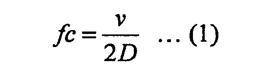
- The present embodiments sets the distance D to D=12 mm according to Equation (1), wherein the phase difference Δϕ approaches π as the frequency of a received sound increases beyond 3 kHz, so that the sound signal SOUT of the
subtracter 21 significantly increases in level. As a result, the level (or the reception sensitivity) of the sound signal SOUT output from the configuration including thesubtracter 21 and thereceivers - In
Fig. 1 , the sound signal SOUT of thesubtracter 21 is input to theHPF 22. TheHPT 22 is provided to adequately attenuate the low frequency range of the sound S when the configuration including thesubtracter 21 and thereceivers HPF 22 outputs a sound signal SOUT' to theamplifier 23. Theamplifier 23 amplifies the sound signal SOUT' so as to output an amplified sound signal SOUT" having a preferable level subjected to transmission between mobile phones conducting conversation. Theadder 24 adds the sound signal SIN of thereceiver 15 and the sound signal SOUT" of theamplifier 23 so as to produce the transmitting sound signal SSND. The transmitting sound signal SSND is supplied to a mobile phone via thecable 11 and transmitted to a counterpart mobile phone. - As described above, the present embodiment is designed to attach the
receiver 15 to the distal end of theinsert portion 13 which is inserted into the user's external auditory canal EAC. In addition, the present embodiment arranges the tworeceivers earphone microphone 10. Thesignal processing unit 20 produces the transmitting sound signal SSND such that the sound signal SOUT (representing the difference between the sound signals SOUT andS OUT2 output from thereceivers 17 and 18) compensates for low frequency components lower than 3 kHz, which are precluded from the sound signal SIN of thereceiver 15. Thus, it is possible to send the transmitting sound signal SSND including a sufficient number of frequency components prerequisite for precisely discriminating the sound S (particularly, consonants of the sound S) to a counterpart listener/talker. - In order to confirm the effect of the present embodiment, the inventor has performed measurement on two samples, i.e. an earphone microphone 10-D12 (in which the distance D between the
receivers receiver 17 out of thereceivers 17, 18). First, the inventor has measured a sound signal SOUT"-D12 which is output from theamplifier 23 of the earphone microphone 10-D12 when thereceivers amplifier 23 of the earphone microphone 10-singl when thereceiver 17 receives a sound emitted from the sound source AS in the direction of θ=0°. Subsequently, the inventor has calculated the ratio (dB) of the sound signal SOUT"-D12 to the sound signal SOUT"-singl with respect to 500 Hz, 1000 Hz, 2000 Hz, 4000 Hz and 8000 Hz (see a first row in Table 1). In addition, the inventor has measured a sound signal SOUT"-D12 which is output from theamplifier 23 of the earphone microphone 10-D12 when thereceivers amplifier 23 of the earphone microphone 10-singl when thereceiver 17 receives a sound emitted from the sound source AS in the direction of θ=90°. Subsequently, the inventor has calculated the ratio (dB) of the sound signal SOUT"-D12 to the sound signal SOUT"-singl with respect to 500 Hz, 1000 Hz, 2000 Hz, 4000 Hz and 8000 Hz (see a second row in Table 1).Table 1 Frequency (Hz) 500 1000 2000 4000 8000 0° -21.6 -18.6 -11.7 -13.3 -2.0 90° -25.6 -29.8 -26.5 -30.3 -27.9 - Table 1 shows that the earphone microphone 10-D12 having the distance of D=12 mm between the
receivers -
Fig. 5 shows three amplitude characteristics with respect to the earphone microphone 10-D12 having the distance of D=12 mm between thereceivers receiver 15 via the user's external auditory canal EAC, R0 denotes an amplitude characteristic of an incoming sound of θ=0° transmitted along an external transmission path from thereceivers amplifier 23, and R90 denotes an amplitude characteristic of an incoming sound of θ=90° transmitted along the external transmission path. Herein, the amplitude characteristic R0 decreases in a frequency range lower than 3 kHz, whilst the amplitude characteristic R90 decreases in the overall frequency range (from a low frequency to a high frequency). Although the amplitude characteristic RIN decreases in a frequency range higher than 3 kHz, the incoming sound of θ=0° (i.e. the user's sound S) compensates for such a reduction of amplitude in frequency components higher than 3 kHz. -
Fig. 6 shows the mechanical/electrical constitution of anearphone microphone 10A according to a second embodiment of the present invention, wherein parts identical to those shown inFig. 1 are designated by the same reference numerals. Compared to theearphone microphone 10 of the first embodiment in which tworeceivers external surface 16 of themain unit 12, theearphone microphone 10A of the second embodiment is equipped with onereceiver 17 which is configured of a unidirectional microphone disposed on theexternal surface 16 of themain unit 12. In theearphone microphone 10A, thereceiver 17 receives an external sound so as to generate a sound signal SOUT, which is supplied to theHPF 22. TheHPF 22 attenuates low frequency components lower than 3 kHz in the sound signal SOUT, thus producing a sound signal SOUT' including frequency components higher than 3 kHz. The sound signal SOUT' is amplified in theamplifier 23, which thus outputs an amplified sound signal SOUT". The sound signal SOUT' includes frequency components higher than 3 kHz, which are useful to linguistically comprehend the user's sound S. The "linguistically comprehensive" sound signal SOUT' is amplified and added to the sound signal SIN representing an internal sound received by thereceiver 15. Theadder 24 adds the sound signals SOUT and SIN so as to produce a sound signal SSND. Thus, theearphone microphone 10A is able to send the sound signal SSND, in which frequency components higher than 3 kHz useful for comprehension of the user's sound S are added to the internal sound received by thereceiver 15, to the counterpart listener/talker over phones. - The second embodiment is characterized in that one
receiver 17 disposed on theexternal surface 16 of themain unit 12 receives the sound S so as to produce the sound signal SOUT, which is subjected to filtering by theHPF 22. The filtered sound signal SOUT' includes frequency components which are lost while the sound S passes through the user's skull and the external auditory canal EAC. In addition, theearphone microphone 10A of the second embodiment can be reduced in size compared to theearphone microphone 10 by reducing the size of themain unit 12. - The present invention is not necessarily limited to the first and second embodiments, which can be further modified in various ways.
- (1) It is possible to modify the
earphone microphone 10 of the first embodiment into anearphone microphone 10B shown inFig. 7 , in which adelay unit 50 is interposed between at least one of thereceivers subtracter 21. In theearphone microphone 10B, thedelay unit 50 delays thesound signal S OUT1 of thereceiver 17 so as to output a delayedsound signal S OUT1", which is supplied to thesubtracter 21. Thesubtracter 21 subtracts the delayedsound signal S OUT1" from thesound signal S OUT2 of thereceiver 18, thus outputting a sound signal SOUT. This variation is advantageous in that the configuration including thesubtracter 21 and thereceivers - (2) The number of receivers disposed on the
external surface 16 of themain unit 12 is not necessarily limited to one or two. It is possible to arrange three or more receivers on theexternal surface 16 of themain unit 12 of theearphone microphone 10. - (3) It is possible to modify the
earphone microphone 10 such that thereceivers - (4) It is possible to modify the
earphone microphones HPT 22 and theamplifier 23 are unified as a single circuitry. - (5) It is possible to modify the
earphone microphone 10 such that thesubtracter 21 is replaced with an adder. The configuration including the adder and thereceivers - (6) It is possible to modify the
earphone microphone 10A such that a directional microphone achieving a high directivity toward a user's mouth is adopted as thereceiver 17 on theexternal surface 16 of themain unit 12. In this case, the frequency characteristic of the directional microphone is adjusted such that the sound signal SOUT of thereceiver 17 can be directly supplied to theamplifier 23 without using theHPF 22 which is unnecessarily interposed between thereceiver 17 and theamplifier 23. - Lastly, the present invention is not necessarily limited to the embodiments and variations, which can be further modified within the scope of the invention defined by the appended claims.
Claims (4)
- An earphone microphone comprising:an insert portion that is inserted into a user's ear;a first receiver attached to a distal end of the insert portion, wherein the first receiver is disposed opposite to a user's eardrum when the insert portion is inserted into a user's external auditory canal;a second receiver attached to an external surface that is exposed and disposed externally of the user's external auditory canal into which the insert portion is inserted; anda signal processor that adds an output signal of the second receiver to an output signal of the first receiver so as to produce a sound signal representing a user's sound.
- The earphone microphone according to claim 1, wherein the second receiver is configured of two receivers, wherein the signal processor includes a subtracter that produces a difference signal between output signals of the two receivers and an adder that adds the difference signal to the output signal of the first receiver so as to produce the sound signal representing the user's sound.
- The earphone microphone according to claim 2, wherein the signal processor further includes a high-pass filter interposed between the subtracter and the adder, wherein the high-pass filter attenuates a low frequency component in the difference signal output from the subtracter.
- The earphone microphone according to claim 2, wherein the two receivers are disposed in a plane, which perpendicularly crosses a center line of the user's external auditory canal into which the insert portion is inserted, with a predetermined distance therebetween.
Applications Claiming Priority (2)
| Application Number | Priority Date | Filing Date | Title |
|---|---|---|---|
| JP2010039296 | 2010-02-24 | ||
| JP2010263676 | 2010-11-26 |
Publications (3)
| Publication Number | Publication Date |
|---|---|
| EP2362677A2 true EP2362677A2 (en) | 2011-08-31 |
| EP2362677A3 EP2362677A3 (en) | 2011-09-14 |
| EP2362677B1 EP2362677B1 (en) | 2017-09-27 |
Family
ID=43837291
Family Applications (1)
| Application Number | Title | Priority Date | Filing Date |
|---|---|---|---|
| EP11001480.0A Not-in-force EP2362677B1 (en) | 2010-02-24 | 2011-02-22 | Earphone microphone |
Country Status (4)
| Country | Link |
|---|---|
| US (1) | US8553922B2 (en) |
| EP (1) | EP2362677B1 (en) |
| JP (1) | JP5691618B2 (en) |
| CN (1) | CN102164326B (en) |
Cited By (2)
| Publication number | Priority date | Publication date | Assignee | Title |
|---|---|---|---|---|
| WO2016148955A3 (en) * | 2015-03-13 | 2016-11-17 | Bose Corporation | Voice sensing using multiple microphones |
| EP3857912B1 (en) | 2018-09-26 | 2025-04-30 | Amazon Technologies Inc. | Beamforming using an in-ear audio device |
Families Citing this family (5)
| Publication number | Priority date | Publication date | Assignee | Title |
|---|---|---|---|---|
| EP3300268B1 (en) * | 2015-05-22 | 2022-10-26 | Toa Corporation | Channel simulation device and channel simulation program |
| KR101773353B1 (en) * | 2016-04-19 | 2017-08-31 | 주식회사 오르페오사운드웍스 | Apparatus and method for compensating timbre |
| US10199029B2 (en) * | 2016-06-23 | 2019-02-05 | Mediatek, Inc. | Speech enhancement for headsets with in-ear microphones |
| KR101803306B1 (en) * | 2016-08-11 | 2017-11-30 | 주식회사 오르페오사운드웍스 | Apparatus and method for monitoring state of wearing earphone |
| CN113038318B (en) * | 2019-12-25 | 2022-06-07 | 荣耀终端有限公司 | Voice signal processing method and device |
Citations (3)
| Publication number | Priority date | Publication date | Assignee | Title |
|---|---|---|---|---|
| JP2007281916A (en) | 2006-04-07 | 2007-10-25 | Nittetsu Elex Co Ltd | Earphone microphone |
| JP2010039296A (en) | 2008-08-06 | 2010-02-18 | Nikon Corp | Camera, camera system, and camera accessory |
| JP2010263676A (en) | 2009-04-30 | 2010-11-18 | Toshiba Corp | Information processing device |
Family Cites Families (17)
| Publication number | Priority date | Publication date | Assignee | Title |
|---|---|---|---|---|
| JPS61206393U (en) * | 1985-06-14 | 1986-12-26 | ||
| JPH0630490A (en) * | 1992-05-12 | 1994-02-04 | Katsuo Motoi | Ear set type transceiver |
| JP2769554B2 (en) * | 1992-07-16 | 1998-06-25 | 登 山口 | Earset type handset |
| US5448637A (en) * | 1992-10-20 | 1995-09-05 | Pan Communications, Inc. | Two-way communications earset |
| JP2000261534A (en) * | 1999-03-10 | 2000-09-22 | Nippon Telegr & Teleph Corp <Ntt> | Handset |
| JP2000354284A (en) * | 1999-06-10 | 2000-12-19 | Iwatsu Electric Co Ltd | Transmitter / receiver using an integrated electro-acoustic transducer |
| US6661901B1 (en) * | 2000-09-01 | 2003-12-09 | Nacre As | Ear terminal with microphone for natural voice rendition |
| US6671379B2 (en) * | 2001-03-30 | 2003-12-30 | Think-A-Move, Ltd. | Ear microphone apparatus and method |
| AU2003296976A1 (en) | 2002-12-11 | 2004-06-30 | Softmax, Inc. | System and method for speech processing using independent component analysis under stability constraints |
| GB2401278B (en) * | 2003-04-30 | 2007-06-06 | Sennheiser Electronic | A device for picking up/reproducing audio signals |
| US7099821B2 (en) | 2003-09-12 | 2006-08-29 | Softmax, Inc. | Separation of target acoustic signals in a multi-transducer arrangement |
| KR20050093538A (en) * | 2004-03-19 | 2005-09-23 | 엘지전자 주식회사 | Reel type ear-mic phone and portable terminal having the same |
| DE102005032274B4 (en) * | 2005-07-11 | 2007-05-10 | Siemens Audiologische Technik Gmbh | Hearing apparatus and corresponding method for eigenvoice detection |
| US8611560B2 (en) * | 2007-04-13 | 2013-12-17 | Navisense | Method and device for voice operated control |
| JP2009130619A (en) * | 2007-11-22 | 2009-06-11 | Funai Electric Advanced Applied Technology Research Institute Inc | Microphone system, sound input apparatus and method for manufacturing the same |
| JP5097523B2 (en) * | 2007-12-07 | 2012-12-12 | 船井電機株式会社 | Voice input device |
| JP4355359B1 (en) * | 2008-05-27 | 2009-10-28 | パナソニック株式会社 | Hearing aid with a microphone installed in the ear canal opening |
-
2011
- 2011-02-21 JP JP2011034865A patent/JP5691618B2/en not_active Expired - Fee Related
- 2011-02-22 US US13/032,595 patent/US8553922B2/en active Active
- 2011-02-22 CN CN201110042783.6A patent/CN102164326B/en not_active Expired - Fee Related
- 2011-02-22 EP EP11001480.0A patent/EP2362677B1/en not_active Not-in-force
Patent Citations (3)
| Publication number | Priority date | Publication date | Assignee | Title |
|---|---|---|---|---|
| JP2007281916A (en) | 2006-04-07 | 2007-10-25 | Nittetsu Elex Co Ltd | Earphone microphone |
| JP2010039296A (en) | 2008-08-06 | 2010-02-18 | Nikon Corp | Camera, camera system, and camera accessory |
| JP2010263676A (en) | 2009-04-30 | 2010-11-18 | Toshiba Corp | Information processing device |
Cited By (3)
| Publication number | Priority date | Publication date | Assignee | Title |
|---|---|---|---|---|
| WO2016148955A3 (en) * | 2015-03-13 | 2016-11-17 | Bose Corporation | Voice sensing using multiple microphones |
| US9905216B2 (en) | 2015-03-13 | 2018-02-27 | Bose Corporation | Voice sensing using multiple microphones |
| EP3857912B1 (en) | 2018-09-26 | 2025-04-30 | Amazon Technologies Inc. | Beamforming using an in-ear audio device |
Also Published As
| Publication number | Publication date |
|---|---|
| EP2362677A3 (en) | 2011-09-14 |
| US20110206229A1 (en) | 2011-08-25 |
| CN102164326B (en) | 2015-11-25 |
| JP5691618B2 (en) | 2015-04-01 |
| US8553922B2 (en) | 2013-10-08 |
| CN102164326A (en) | 2011-08-24 |
| JP2012129970A (en) | 2012-07-05 |
| EP2362677B1 (en) | 2017-09-27 |
Similar Documents
| Publication | Publication Date | Title |
|---|---|---|
| US12348932B2 (en) | Hearing assistance using active noise reduction | |
| EP3114825B1 (en) | Frequency-dependent sidetone calibration | |
| CN107426643B (en) | Uplink noise cancelling headphone | |
| US8144891B2 (en) | Earphone set | |
| US10341759B2 (en) | System and method of wind and noise reduction for a headphone | |
| US9542957B2 (en) | Procedure and mechanism for controlling and using voice communication | |
| US8553922B2 (en) | Earphone microphone | |
| US20160293156A1 (en) | In-ear headphones with noise reduction effect | |
| US10199029B2 (en) | Speech enhancement for headsets with in-ear microphones | |
| US9654855B2 (en) | Self-voice occlusion mitigation in headsets | |
| WO2004016037A1 (en) | Method of increasing speech intelligibility and device therefor | |
| WO2008139931A1 (en) | Earphone microphone | |
| JP2009141698A (en) | Headset | |
| JP2004504785A (en) | Audio headset | |
| CN111713120B (en) | Earphone with system for reducing ambient noise | |
| CN101437190A (en) | Earphone with hearing aid function | |
| US20190174006A1 (en) | Speakerphone system or speakerphone accessory with on-cable microphone | |
| JP2024500180A (en) | Ear-hook personal audio device | |
| KR101022312B1 (en) | Ear microphone | |
| US12081944B1 (en) | Audio device apparatus for hearing impaired users | |
| JPH08340590A (en) | Earphone/microphone set | |
| JP2007228344A (en) | Transmitter-receiver system | |
| KR20170018554A (en) | Sound Filtering System | |
| JP2006173930A (en) | Transmitter/receiver, and earphone microphone | |
| KR20020077750A (en) | Electromagnetic waves protection type hands-free kit |
Legal Events
| Date | Code | Title | Description |
|---|---|---|---|
| PUAI | Public reference made under article 153(3) epc to a published international application that has entered the european phase |
Free format text: ORIGINAL CODE: 0009012 |
|
| PUAL | Search report despatched |
Free format text: ORIGINAL CODE: 0009013 |
|
| AK | Designated contracting states |
Kind code of ref document: A2 Designated state(s): AL AT BE BG CH CY CZ DE DK EE ES FI FR GB GR HR HU IE IS IT LI LT LU LV MC MK MT NL NO PL PT RO RS SE SI SK SM TR |
|
| AX | Request for extension of the european patent |
Extension state: BA ME |
|
| AK | Designated contracting states |
Kind code of ref document: A3 Designated state(s): AL AT BE BG CH CY CZ DE DK EE ES FI FR GB GR HR HU IE IS IT LI LT LU LV MC MK MT NL NO PL PT RO RS SE SI SK SM TR |
|
| AX | Request for extension of the european patent |
Extension state: BA ME |
|
| RIC1 | Information provided on ipc code assigned before grant |
Ipc: H04R 1/08 20060101ALN20110809BHEP Ipc: H04R 3/00 20060101AFI20110809BHEP Ipc: H04R 1/10 20060101ALN20110809BHEP |
|
| 17P | Request for examination filed |
Effective date: 20120314 |
|
| 17Q | First examination report despatched |
Effective date: 20160630 |
|
| REG | Reference to a national code |
Ref country code: DE Ref legal event code: R079 Ref document number: 602011041826 Country of ref document: DE Free format text: PREVIOUS MAIN CLASS: H04R0001080000 Ipc: H04R0003000000 |
|
| GRAP | Despatch of communication of intention to grant a patent |
Free format text: ORIGINAL CODE: EPIDOSNIGR1 |
|
| RIC1 | Information provided on ipc code assigned before grant |
Ipc: H04R 3/00 20060101AFI20170320BHEP Ipc: H04R 1/10 20060101ALN20170320BHEP |
|
| INTG | Intention to grant announced |
Effective date: 20170406 |
|
| GRAS | Grant fee paid |
Free format text: ORIGINAL CODE: EPIDOSNIGR3 |
|
| GRAA | (expected) grant |
Free format text: ORIGINAL CODE: 0009210 |
|
| AK | Designated contracting states |
Kind code of ref document: B1 Designated state(s): AL AT BE BG CH CY CZ DE DK EE ES FI FR GB GR HR HU IE IS IT LI LT LU LV MC MK MT NL NO PL PT RO RS SE SI SK SM TR |
|
| REG | Reference to a national code |
Ref country code: GB Ref legal event code: FG4D |
|
| REG | Reference to a national code |
Ref country code: CH Ref legal event code: EP |
|
| REG | Reference to a national code |
Ref country code: AT Ref legal event code: REF Ref document number: 933025 Country of ref document: AT Kind code of ref document: T Effective date: 20171015 |
|
| REG | Reference to a national code |
Ref country code: IE Ref legal event code: FG4D |
|
| REG | Reference to a national code |
Ref country code: DE Ref legal event code: R096 Ref document number: 602011041826 Country of ref document: DE |
|
| PG25 | Lapsed in a contracting state [announced via postgrant information from national office to epo] |
Ref country code: FI Free format text: LAPSE BECAUSE OF FAILURE TO SUBMIT A TRANSLATION OF THE DESCRIPTION OR TO PAY THE FEE WITHIN THE PRESCRIBED TIME-LIMIT Effective date: 20170927 Ref country code: HR Free format text: LAPSE BECAUSE OF FAILURE TO SUBMIT A TRANSLATION OF THE DESCRIPTION OR TO PAY THE FEE WITHIN THE PRESCRIBED TIME-LIMIT Effective date: 20170927 Ref country code: NO Free format text: LAPSE BECAUSE OF FAILURE TO SUBMIT A TRANSLATION OF THE DESCRIPTION OR TO PAY THE FEE WITHIN THE PRESCRIBED TIME-LIMIT Effective date: 20171227 Ref country code: SE Free format text: LAPSE BECAUSE OF FAILURE TO SUBMIT A TRANSLATION OF THE DESCRIPTION OR TO PAY THE FEE WITHIN THE PRESCRIBED TIME-LIMIT Effective date: 20170927 Ref country code: LT Free format text: LAPSE BECAUSE OF FAILURE TO SUBMIT A TRANSLATION OF THE DESCRIPTION OR TO PAY THE FEE WITHIN THE PRESCRIBED TIME-LIMIT Effective date: 20170927 |
|
| REG | Reference to a national code |
Ref country code: NL Ref legal event code: MP Effective date: 20170927 |
|
| REG | Reference to a national code |
Ref country code: LT Ref legal event code: MG4D |
|
| REG | Reference to a national code |
Ref country code: AT Ref legal event code: MK05 Ref document number: 933025 Country of ref document: AT Kind code of ref document: T Effective date: 20170927 |
|
| PG25 | Lapsed in a contracting state [announced via postgrant information from national office to epo] |
Ref country code: LV Free format text: LAPSE BECAUSE OF FAILURE TO SUBMIT A TRANSLATION OF THE DESCRIPTION OR TO PAY THE FEE WITHIN THE PRESCRIBED TIME-LIMIT Effective date: 20170927 Ref country code: RS Free format text: LAPSE BECAUSE OF FAILURE TO SUBMIT A TRANSLATION OF THE DESCRIPTION OR TO PAY THE FEE WITHIN THE PRESCRIBED TIME-LIMIT Effective date: 20170927 Ref country code: BG Free format text: LAPSE BECAUSE OF FAILURE TO SUBMIT A TRANSLATION OF THE DESCRIPTION OR TO PAY THE FEE WITHIN THE PRESCRIBED TIME-LIMIT Effective date: 20171227 Ref country code: GR Free format text: LAPSE BECAUSE OF FAILURE TO SUBMIT A TRANSLATION OF THE DESCRIPTION OR TO PAY THE FEE WITHIN THE PRESCRIBED TIME-LIMIT Effective date: 20171228 |
|
| PG25 | Lapsed in a contracting state [announced via postgrant information from national office to epo] |
Ref country code: NL Free format text: LAPSE BECAUSE OF FAILURE TO SUBMIT A TRANSLATION OF THE DESCRIPTION OR TO PAY THE FEE WITHIN THE PRESCRIBED TIME-LIMIT Effective date: 20170927 |
|
| PG25 | Lapsed in a contracting state [announced via postgrant information from national office to epo] |
Ref country code: RO Free format text: LAPSE BECAUSE OF FAILURE TO SUBMIT A TRANSLATION OF THE DESCRIPTION OR TO PAY THE FEE WITHIN THE PRESCRIBED TIME-LIMIT Effective date: 20170927 Ref country code: CZ Free format text: LAPSE BECAUSE OF FAILURE TO SUBMIT A TRANSLATION OF THE DESCRIPTION OR TO PAY THE FEE WITHIN THE PRESCRIBED TIME-LIMIT Effective date: 20170927 Ref country code: ES Free format text: LAPSE BECAUSE OF FAILURE TO SUBMIT A TRANSLATION OF THE DESCRIPTION OR TO PAY THE FEE WITHIN THE PRESCRIBED TIME-LIMIT Effective date: 20170927 |
|
| PG25 | Lapsed in a contracting state [announced via postgrant information from national office to epo] |
Ref country code: SM Free format text: LAPSE BECAUSE OF FAILURE TO SUBMIT A TRANSLATION OF THE DESCRIPTION OR TO PAY THE FEE WITHIN THE PRESCRIBED TIME-LIMIT Effective date: 20170927 Ref country code: SK Free format text: LAPSE BECAUSE OF FAILURE TO SUBMIT A TRANSLATION OF THE DESCRIPTION OR TO PAY THE FEE WITHIN THE PRESCRIBED TIME-LIMIT Effective date: 20170927 Ref country code: IS Free format text: LAPSE BECAUSE OF FAILURE TO SUBMIT A TRANSLATION OF THE DESCRIPTION OR TO PAY THE FEE WITHIN THE PRESCRIBED TIME-LIMIT Effective date: 20180127 Ref country code: IT Free format text: LAPSE BECAUSE OF FAILURE TO SUBMIT A TRANSLATION OF THE DESCRIPTION OR TO PAY THE FEE WITHIN THE PRESCRIBED TIME-LIMIT Effective date: 20170927 Ref country code: EE Free format text: LAPSE BECAUSE OF FAILURE TO SUBMIT A TRANSLATION OF THE DESCRIPTION OR TO PAY THE FEE WITHIN THE PRESCRIBED TIME-LIMIT Effective date: 20170927 Ref country code: AT Free format text: LAPSE BECAUSE OF FAILURE TO SUBMIT A TRANSLATION OF THE DESCRIPTION OR TO PAY THE FEE WITHIN THE PRESCRIBED TIME-LIMIT Effective date: 20170927 |
|
| REG | Reference to a national code |
Ref country code: DE Ref legal event code: R097 Ref document number: 602011041826 Country of ref document: DE |
|
| PG25 | Lapsed in a contracting state [announced via postgrant information from national office to epo] |
Ref country code: DK Free format text: LAPSE BECAUSE OF FAILURE TO SUBMIT A TRANSLATION OF THE DESCRIPTION OR TO PAY THE FEE WITHIN THE PRESCRIBED TIME-LIMIT Effective date: 20170927 |
|
| PLBE | No opposition filed within time limit |
Free format text: ORIGINAL CODE: 0009261 |
|
| STAA | Information on the status of an ep patent application or granted ep patent |
Free format text: STATUS: NO OPPOSITION FILED WITHIN TIME LIMIT |
|
| PG25 | Lapsed in a contracting state [announced via postgrant information from national office to epo] |
Ref country code: PL Free format text: LAPSE BECAUSE OF FAILURE TO SUBMIT A TRANSLATION OF THE DESCRIPTION OR TO PAY THE FEE WITHIN THE PRESCRIBED TIME-LIMIT Effective date: 20170927 |
|
| 26N | No opposition filed |
Effective date: 20180628 |
|
| REG | Reference to a national code |
Ref country code: CH Ref legal event code: PL |
|
| PG25 | Lapsed in a contracting state [announced via postgrant information from national office to epo] |
Ref country code: MC Free format text: LAPSE BECAUSE OF FAILURE TO SUBMIT A TRANSLATION OF THE DESCRIPTION OR TO PAY THE FEE WITHIN THE PRESCRIBED TIME-LIMIT Effective date: 20170927 |
|
| REG | Reference to a national code |
Ref country code: IE Ref legal event code: MM4A |
|
| REG | Reference to a national code |
Ref country code: BE Ref legal event code: MM Effective date: 20180228 |
|
| PG25 | Lapsed in a contracting state [announced via postgrant information from national office to epo] |
Ref country code: LI Free format text: LAPSE BECAUSE OF NON-PAYMENT OF DUE FEES Effective date: 20180228 Ref country code: CH Free format text: LAPSE BECAUSE OF NON-PAYMENT OF DUE FEES Effective date: 20180228 Ref country code: SI Free format text: LAPSE BECAUSE OF FAILURE TO SUBMIT A TRANSLATION OF THE DESCRIPTION OR TO PAY THE FEE WITHIN THE PRESCRIBED TIME-LIMIT Effective date: 20170927 Ref country code: LU Free format text: LAPSE BECAUSE OF NON-PAYMENT OF DUE FEES Effective date: 20180222 |
|
| REG | Reference to a national code |
Ref country code: FR Ref legal event code: ST Effective date: 20181031 |
|
| PG25 | Lapsed in a contracting state [announced via postgrant information from national office to epo] |
Ref country code: IE Free format text: LAPSE BECAUSE OF NON-PAYMENT OF DUE FEES Effective date: 20180222 |
|
| PG25 | Lapsed in a contracting state [announced via postgrant information from national office to epo] |
Ref country code: FR Free format text: LAPSE BECAUSE OF NON-PAYMENT OF DUE FEES Effective date: 20180228 Ref country code: BE Free format text: LAPSE BECAUSE OF NON-PAYMENT OF DUE FEES Effective date: 20180228 |
|
| PG25 | Lapsed in a contracting state [announced via postgrant information from national office to epo] |
Ref country code: MT Free format text: LAPSE BECAUSE OF NON-PAYMENT OF DUE FEES Effective date: 20180222 |
|
| PG25 | Lapsed in a contracting state [announced via postgrant information from national office to epo] |
Ref country code: TR Free format text: LAPSE BECAUSE OF FAILURE TO SUBMIT A TRANSLATION OF THE DESCRIPTION OR TO PAY THE FEE WITHIN THE PRESCRIBED TIME-LIMIT Effective date: 20170927 |
|
| PG25 | Lapsed in a contracting state [announced via postgrant information from national office to epo] |
Ref country code: HU Free format text: LAPSE BECAUSE OF FAILURE TO SUBMIT A TRANSLATION OF THE DESCRIPTION OR TO PAY THE FEE WITHIN THE PRESCRIBED TIME-LIMIT; INVALID AB INITIO Effective date: 20110222 Ref country code: PT Free format text: LAPSE BECAUSE OF FAILURE TO SUBMIT A TRANSLATION OF THE DESCRIPTION OR TO PAY THE FEE WITHIN THE PRESCRIBED TIME-LIMIT Effective date: 20170927 |
|
| PG25 | Lapsed in a contracting state [announced via postgrant information from national office to epo] |
Ref country code: MK Free format text: LAPSE BECAUSE OF NON-PAYMENT OF DUE FEES Effective date: 20170927 Ref country code: CY Free format text: LAPSE BECAUSE OF FAILURE TO SUBMIT A TRANSLATION OF THE DESCRIPTION OR TO PAY THE FEE WITHIN THE PRESCRIBED TIME-LIMIT Effective date: 20170927 |
|
| PG25 | Lapsed in a contracting state [announced via postgrant information from national office to epo] |
Ref country code: AL Free format text: LAPSE BECAUSE OF FAILURE TO SUBMIT A TRANSLATION OF THE DESCRIPTION OR TO PAY THE FEE WITHIN THE PRESCRIBED TIME-LIMIT Effective date: 20170927 |
|
| PGFP | Annual fee paid to national office [announced via postgrant information from national office to epo] |
Ref country code: GB Payment date: 20220223 Year of fee payment: 12 |
|
| PGFP | Annual fee paid to national office [announced via postgrant information from national office to epo] |
Ref country code: DE Payment date: 20220620 Year of fee payment: 13 |
|
| GBPC | Gb: european patent ceased through non-payment of renewal fee |
Effective date: 20230222 |
|
| PG25 | Lapsed in a contracting state [announced via postgrant information from national office to epo] |
Ref country code: GB Free format text: LAPSE BECAUSE OF NON-PAYMENT OF DUE FEES Effective date: 20230222 |
|
| PG25 | Lapsed in a contracting state [announced via postgrant information from national office to epo] |
Ref country code: GB Free format text: LAPSE BECAUSE OF NON-PAYMENT OF DUE FEES Effective date: 20230222 |
|
| REG | Reference to a national code |
Ref country code: DE Ref legal event code: R119 Ref document number: 602011041826 Country of ref document: DE |
|
| PG25 | Lapsed in a contracting state [announced via postgrant information from national office to epo] |
Ref country code: DE Free format text: LAPSE BECAUSE OF NON-PAYMENT OF DUE FEES Effective date: 20240903 |
|
| PG25 | Lapsed in a contracting state [announced via postgrant information from national office to epo] |
Ref country code: DE Free format text: LAPSE BECAUSE OF NON-PAYMENT OF DUE FEES Effective date: 20240903 |