EP2362584A1 - System and method for frequency division multiplexed high speed physical layer devices - Google Patents
System and method for frequency division multiplexed high speed physical layer devices Download PDFInfo
- Publication number
- EP2362584A1 EP2362584A1 EP11001232A EP11001232A EP2362584A1 EP 2362584 A1 EP2362584 A1 EP 2362584A1 EP 11001232 A EP11001232 A EP 11001232A EP 11001232 A EP11001232 A EP 11001232A EP 2362584 A1 EP2362584 A1 EP 2362584A1
- Authority
- EP
- European Patent Office
- Prior art keywords
- ethernet
- baseband
- transmitters
- baseband ethernet
- transmitter
- Prior art date
- Legal status (The legal status is an assumption and is not a legal conclusion. Google has not performed a legal analysis and makes no representation as to the accuracy of the status listed.)
- Granted
Links
Images


Classifications
-
- H—ELECTRICITY
- H04—ELECTRIC COMMUNICATION TECHNIQUE
- H04L—TRANSMISSION OF DIGITAL INFORMATION, e.g. TELEGRAPHIC COMMUNICATION
- H04L49/00—Packet switching elements
- H04L49/35—Switches specially adapted for specific applications
- H04L49/351—Switches specially adapted for specific applications for local area network [LAN], e.g. Ethernet switches
- H04L49/352—Gigabit ethernet switching [GBPS]
-
- H—ELECTRICITY
- H04—ELECTRIC COMMUNICATION TECHNIQUE
- H04L—TRANSMISSION OF DIGITAL INFORMATION, e.g. TELEGRAPHIC COMMUNICATION
- H04L43/00—Arrangements for monitoring or testing data switching networks
- H04L43/08—Monitoring or testing based on specific metrics, e.g. QoS, energy consumption or environmental parameters
- H04L43/0876—Network utilisation, e.g. volume of load or congestion level
- H04L43/0882—Utilisation of link capacity
-
- H—ELECTRICITY
- H04—ELECTRIC COMMUNICATION TECHNIQUE
- H04L—TRANSMISSION OF DIGITAL INFORMATION, e.g. TELEGRAPHIC COMMUNICATION
- H04L47/00—Traffic control in data switching networks
- H04L47/10—Flow control; Congestion control
Definitions
- the present invention relates generally to Ethernet systems and methods and, more particularly, to a system and method for frequency division multiplexed high speed physical layer devices.
- Ethernet devices continue to evolve in capability as the incremental increases in the standardized transmission rates have progressed by orders of magnitude.
- transmission rates for standardized Ethernet devices have progressed from 10 Mbit/s to 100 Mbit/s, from 100 Mbit/s to 1 Gbit/s, and more recently, from 1 Gbit/s to 10 Gbit/s.
- Efforts are ongoing to identify the next transmission rate that is to be adopted as the next standard of Ethernet performance. Whether 40 Gbit/s or 100 Gbit/s, the next transmission rate will be significantly higher than 10 Gbit/s.
- an Ethernet communication system comprising:
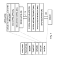
- FIG. 1 illustrates an OSI layering diagram
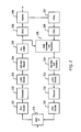
- FIG. 2 illustrates an example of an Ethernet physical layer device.
- FIG. 3 illustrates an example embodiment of frequency division multiplexing in an Ethernet physical layer device.
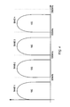
- FIG. 4 illustrates an example of a frequency spectrum used by a frequency division multiplexing Ethernet physical layer device.
- FIG. 5 illustrates a flowchart of a process of the present invention.
- Ethernet has become an increasingly pervasive technology that has been applied in various contexts, including twisted pair, backplane, and optical applications.
- the inherent simplicity of Ethernet has enabled application of the technology to various mediums, various speeds, and various distances. These features have enabled Ethernet to become a viable technology option that spans high-speed laboratory networks, commercial networks, and increasingly to consumer networks.
- Ethernet transmission rates have seen rapid advancement with order-of-magnitude increases in transmission rates being made available in new generations of Ethernet devices. These substantial increases in transmission rates come with certain implementation costs, however, as increases in system complexity, increases in costs for physical plant improvements (e.g., cabling), increases in power consumed, etc. have balanced the benefit of the increase in transmission rate. These implementation costs represent real design challenges when considering the next generation of Ethernet devices (e.g., 40 Gbit/s or 100 Gbit/s).
- FIG. 1 illustrates the ISO Open System Interconnection (OSI) reference model and its mapping to the IEEE 802.3 layering.
- OSI Open System Interconnection
- the PHY includes a physical coding sublayer (PCS), a physical medium attachment (PMA), physical media dependent (PMD), and auto-negotiation (AN).
- PCS physical coding sublayer
- PMA physical medium attachment
- PMD physical media dependent
- AN auto-negotiation
- MDI medium dependent interface
- the physical layer (often referred to as the PHY) includes a physical coding sublayer (PCS), a physical medium attachment (PMA), physical media dependent (PMD), and auto-negotiation (AN).
- PCS physical coding sublayer
- PMA physical medium attachment
- PMD physical media dependent
- AN auto-negotiation
- the PCS is coupled to a reconciliation sublayer (RS), which provides a signal mapping between interface 110 and the MAC layer.
- RS reconciliation sublayer
- interface 110 can be based on an Attachment Unit Interface (AUI), media independent interface (MII), serial MII (SMII), reduced MII, (RMII), gigabit MII (GMII), reduced GMII (RGMII), serial GMII (SGMII), quad serial gigabit MII (QSGMII), 10 gigabit MII (XGMII), SXGMII, XFI, 10-Gbps AUI (XAUI), 40 gigabit MII (XLGMII), 40-Gbps AUI (XLAUI), 100 gigabit MII (CGMII), 10Gbps AUI (CAUI), or the like.
- one or more parts of the PHY can be internal or external to the MAC.
- an extender such as the XAUI extender sublayer (XGXS) or XFI can be used between the MAC/PHY. Similar extenders such as XLAUI and CAUI can also be defined for higher transmission rates.
- the PMA abstracts the PCS from the physical medium. Accordingly, the PCS can be unaware of the type of medium.
- the primary functions of the PMA include mapping of transmit and receive code-groups between the PCS and PMA, serialization/de-serialization of code-groups for transmission/reception on the underlying PMD, recovery of clock from the coded data (e.g., 4B/5B, 8B/10B, 64B/65B, 64B/66B, etc.) supplied by the PMD, and mapping of transmit and receive bits between the PMA and PMD.
- the PMD is generally responsible for generating electrical or optical signals depending on the nature of the physical medium connected. PMD signals are sent to the medium dependent interface (MDI), which is the actual medium connected, including connectors, for the various media supported.
- MDI medium dependent interface
- AN provides a linked device with the capability to detect the abilities (modes of operation) supported by the device at the other end of the link, determine common abilities, and configure for joint operation.
- the AN process identifies the best possible mode of operation (or highest common denominator) that is shared by the two PHY devices.
- a particular priority between different modes of operation can be defined, for example, where a higher speed is preferred over a lower speed, and full duplex is preferred over half duplex at the same speed.
- AN can also be applied asymmetrically to a link.
- the AN can be designed to support multiple modes.
- the AN can be designed to support a 40 Gbit/s PHY operating mode in addition to standard operating modes at 10 Mbit/s, 100 Mbit/s, 1 Gbit/s, and 10 Gbit/s over structured cabling.
- the AN can be designed to select from a plural set of operating modes that include non-standard operating modes (e.g., 2.5 Gbit/s, 5 Gbit/s, etc. transmission over structured cabling) in addition to the standard operating modes noted above.
- the AN can be used to autonegotiate to a variable rate.
- each PHY can test the channel and exchange information regarding the channel (e.g., type of cable, length of cable, etc.), which information can be used to select a particular operating mode.
- the AN process can select a 40 Gbit/s transmission rate if Category 7A cabling is detected, select a 10 Gbit/s transmission rate if Category 6A cabling is detected, select a 40 Gbit/s transmission rate if 15 meters of Category 6A cabling is detected, etc.
- the AN process can be designed to select an operating mode based not only on the capabilities of the PHYs themselves, but also the capabilities of the particular communication channel between them.
- Ethernet-compatible cabling Various types exist. For example, performance characteristics represented by Category 3 unshielded twisted pair cabling enable 10BASE-T transmission but not 100BASE-TX transmission, which requires performance characteristics exhibited by Category 5 or 5e cabling.
- Category 6 cabling was then defined as the cable standard for supporting 1000BASE-T operation. Since that time, cabling advancements have led to advanced Category 6A, 7, 7A, which can support frequencies up to 1 Ghz, and enhanced 7A or newer cabling, which can support frequencies up to 2 Ghz and beyond.
- the transmission rate on the twisted pair link is dependent on the channel conditions, which itself is dependent on the type of cabling, length of cabling, connectors, etc.
- the newer enhanced 7A cabling has up to 2 Ghz of bandwidth. This large amount of bandwidth is believed to be sufficient to support 40GBASE-T transmission.
- the PHY transceiver includes MAC I/F 210, which can be designed to support XGMII or XAUI interfaces, as an example.
- the PHY transceiver can include PCS encode 221, Scrambler 222, Low Density Parity Check (LDPC) 223, 128 Double Square (DSQ) Mapper 224, Pre-Coders 225, Digital-Analog Converters (DACs) 226, and Hybrids 240.
- PCS encode 221 Scrambler 222
- LDPC Low Density Parity Check
- DSQ 128 Double Square Mapper 224
- Pre-Coders 225 Pre-Coders 225
- DACs Digital-Analog Converters
- Hybrids 240 Hybrids 240.
- VGAs Variable Gain Amplifiers
- ADCs Analog-Digital Converters
- Xtalk Crosstalk Cancellers and Equalizers 235
- 128 DSQ Soft Decisions 234 LDPC Decode 233, Descrambler 232, and PCS decode 231, which delivers signals to MAC I/F 210.
- this architecture reuse can provide a simple mechanism to increase transmission capacity, while obviating the need to incur the large incremental expenses of transitioning to a newly-designed architecture that supports the next standardized transmission rate.
- FIG. 3 illustrates an example embodiment of leveraging an existing architecture.
- demultiplexer 310 receives a transmission (TX) data stream and outputs four demultiplexed data streams to baseband transmitters 322, 324, 326, 328.
- TX transmission
- the received TX data stream is a 40 Gbit/s data stream
- the four demultiplexed data streams are each 10 Gbit/s data streams.
- the principles of the present invention are not dependent on particular combinations of data transmission rates. For example, different ratios of demultiplexing can be used to match a given set of baseband transmitters.
- demultiplexer 310 is designed to produce four 10 Gbit/s demultiplexed data streams.
- Each of these 10 Gbit/s demultiplexed data streams can be processed by baseband transmitters 322, 324, 326, 328 that can implement an existing 10G architecture such as that illustrated in FIG. 2 .
- each baseband transmitter 322, 324, 326, 328 can implement a conventional 10GBASE-T signaling scheme.
- the outputs of baseband transmitters 322, 324, 326, 328 are fed to respective mixers 332, 334, 336, 338.
- Mixers 332, 334, 336, 338 are designed to implement a frequency division multiplexing scheme, wherein the outputs of at least baseband transmitters 324, 326, 328 are frequency shifted to different parts of the frequency spectrum of the twisted pair communication channel.
- Fig. 4 illustrates an example of the frequency spectrum of a 40 Gbit/s data stream being transmitted over enhanced 7A cabling using frequency division multiplexing.
- enhanced 7A cabling has a bandwidth of about 2 Ghz.
- Each 10GBASE-T baseband transmitter would require approximately 400 Mhz of bandwidth.
- the 2 Ghz of frequency spectrum can be divided into four 500 Mhz bands 1-4, wherein each 500 Mhz band is designed to carry the output of one of the baseband transmitters.
- usable ranges of 0-400 Mhz, 500-900 Mhz, 1000-1400 Mhz, and 1500-1900 Mhz approximately 100 Mhz of spacing is included between the frequency-shifted outputs of the baseband transmitters.
- the usable frequency spectrum would be dependent on the cabling selected, which can be selected to facilitate a given number and combination of baseband transmitters, whose combined operating modes would yield the desired throughput.
- the receiving end includes mixers 342, 344, 346, 348, which are designed to capture the baseband signals from the different frequency bands.
- the outputs of mixers 342, 344, 346, 348 are then provided to respective baseband receivers 352, 354, 356, 358.
- FIG. 2 illustrates an existing architecture of a 10GBASE-T receiver that can be used by baseband receivers 352, 354, 356, 358.
- the outputs of baseband receivers 352, 354, 356, 358 are provided to multiplexer 360, which generates the received 40 Gbit/s data stream.
- frequency division multiplexing for a twisted cable channel promotes architecture reuse.
- This architecture reuse enables an efficient scaling mechanism, which reduces the large implementation costs of the next-generation of Ethernet devices.
- one of the advantages of the scaling mechanism is that efficient transitions can be made to intermediate rates instead of the next highest standardized rate. For example, by using two sets of 10 Gbit/s baseband transmitters and receivers, a 20 Gbit/s link rate can be supported on a cabling infrastructure that has a bandwidth of 1 Ghz. A low-cost gradual migration path is therefore enabled.
- the frequency division multiplexed scheme can be used without demultiplexer 310 and multiplexer 360.
- baseband transmitters 322, 324, 326, 328 can be used as part of an integrated quad-PHY die that supports four separate 10 Gbit/s channels, and includes a controller, switches, buffering, connectors, etc.
- the frequency division multiplexing scheme creates four separate virtual wires out of one wire, effectively quadrupling the capacity of the cabling.
- multiple modes can be supported by the 40 Gbit/s PHY.
- all four baseband transmitters 322, 324, 326, 328 can be used for a 40 Gbit/s mode, while only a single baseband transmitter (e.g., 322) is used for a 10 Gbit/s mode.
- the single baseband transmitter also supports legacy modes (standardized and/or non-standardized), than other modes such as 5 Gbit/s, 2.5 Gbit/s, 1 Gbit/s 100 Mbit/s, 10 Mbit/s modes can also be supported by the Ethernet device. Selection of one of these various operating modes can be enabled by an AN that supports a selection from among the frequency division multiplexed 40 Gbit/s operating mode, non-multiplexed 10 Gbit/s operating mode, and existing standardized/non-standardized operating modes.
- FIG. 5 illustrates an energy efficient Ethernet (EEE) application for which the multiple modes of the frequency division multiplexed device can be used.
- EEE energy efficient Ethernet
- energy costs are a key consideration in any implementation, especially those that support higher transmission rates.
- Energy efficiency is a key consideration in Ethernet devices as energy costs continue to escalate in a trend that has accelerated in recent years.
- an EEE process begins at step 502 where a frequency division multiplexed Ethernet device is configured in an operating state.
- the frequency division multiplexed Ethernet device can be configured for 40G operation with four 10G baseband transmitters being used.
- the process continues to step 504 where the link utilization is monitored.
- the link utilization can be monitored by an EEE control policy that can be designed to determine when to enter a power saving state, what power saving state (i.e., level of power savings) to enter, how long to remain in that power saving state, what power saving state to transition to out of the previous power saving state, etc.
- An EEE control policy entity can include software code that can interoperate with one or more layers, including portions of the PHY, MAC, switch, or other subsystems in the host.
- the EEE control policy is inside the PHY.
- the EEE control policy entity can be enabled to analyze traffic on the physical link and to analyze operations and/or processing of data in itself or in its link partner.
- the EEE control policy entity can exchange information from, or pertaining to, one or more layers of the OSI hierarchy in order to establish and/or implement the EEE control policy.
- the software-based EEE control policy can be designed to base its decisions on a combination of static settings established by an IT manager, default software configuration, properties of the traffic bandwidth on the link itself, time of day, or by some other set of fixed parameters.
- the EEE control policy can be designed to examine empty or non-empty conditions of ports, queues, buffers, etc. to determine whether to transition to or from a power saving state.
- step 506 while the link utilization is monitored, it is then determined whether the monitored link utilization indicates a state transition is needed. If it is determined that a state transition is not needed, then the process continues to monitor the link utilization. If, on the other hand, it is determined that a state transition is needed, the process then continues back to step 502 where the frequency division multiplexed Ethernet device's operating state is configured.
- the frequency division multiplexed Ethernet device can be configured to transition from the previous active 40G state to a low power state.
- the low power state of the frequency division multiplexed Ethernet device can be configured by lowering the power consumption of one or more of the 10G baseband transmitter channels.
- one of the higher frequency-shifted outputs can be turned off yielding a throughput of 30G, or one of the baseband transmitters can be turned off while a second baseband transmitter selects a 5G operating mode, thereby yielding a throughput of 25G, or all but one of the baseband transmitters is turned off yielding a throughput (e.g., 10G, 5G, 2.5G, 1G, 100M, 10M) of the operating mode selected for the lone active baseband transmitter.
- the frequency division multiplexed Ethernet device can continue in the selected low power operating state until the link utilization indicates that a return to the active 40G operating state is required.
- the frequency division multiplexed Ethernet device can support a variety of operating modes that can support different configurations at startup or during active operation.
- the flexibility of the operating modes is enabled by architecture reuse that enables efficient scaling.
- M 1G baseband transmitters can be used to produce a frequency division multiplexed M*G Ethernet device.
- the principles of the present invention are not to be construed to be limited to the 10G example of FIG. 2 . More generally, the principles of the present invention can be applied to any existing architecture, including, 10 Mbit/s, 100 Mbit/s, 1 Gbit/s, 10 Gbit/s (e.g., 10GBASE-KR, KX4, CR1), 40 Gbit/s (e.g., 40GBASE-CR4), 100 Gbit/s (e.g., 100GBASE-CR10), etc. systems.
- 10 Mbit/s 100 Mbit/s, 1 Gbit/s, 10 Gbit/s (e.g., 10GBASE-KR, KX4, CR1), 40 Gbit/s (e.g., 40GBASE-CR4), 100 Gbit/s (e.g., 100GBASE-CR10), etc. systems.
- the principles of the present invention can also be applied to various standard, non-standard (e.g., 2.5 Gbit/s, 5 Gbit/s, 20 Gbit/s, 25 Gbit/s, 28 Gbit/s, etc.), or future (e.g., 40 Gbit/s, 100 Gbit/s, 250 Gbit/s, 400 Gbit/s, 1000 Gbit/s, etc.) link rate systems.
- the principles of the present invention can also be applied to shared media links like passive optical networks (PONs) and to point-to-point (P2P) fiber optic networks.
- PONs passive optical networks
- P2P point-to-point
- a variable rate frequency division multiplexed Ethernet device can be generated that is responsive to the channel properties (e.g., type of cable, length of cable, bundling constraints, etc.) discovered by the channel diagnostics. This information can then be used to select the particular number and combination of baseband transmitters/receivers (i.e., need not be the same) to facilitate the bandwidth needs relative to the particular channel.
- the particular device implementation would be dependent on the baseband transmitters/receivers being used, the amount of cabling bandwidth available, the efficiency of use of the cabling bandwidth available (e.g., carrier spacing), etc.
- the principles of the present invention can also be applied asymmetrically to a link.
Landscapes
- Engineering & Computer Science (AREA)
- Computer Networks & Wireless Communication (AREA)
- Signal Processing (AREA)
- Environmental & Geological Engineering (AREA)
- Small-Scale Networks (AREA)
- Communication Control (AREA)
- Time-Division Multiplex Systems (AREA)
Abstract
Description
- The present invention relates generally to Ethernet systems and methods and, more particularly, to a system and method for frequency division multiplexed high speed physical layer devices.
- Ethernet devices continue to evolve in capability as the incremental increases in the standardized transmission rates have progressed by orders of magnitude. In a relatively short period of time, transmission rates for standardized Ethernet devices have progressed from 10 Mbit/s to 100 Mbit/s, from 100 Mbit/s to 1 Gbit/s, and more recently, from 1 Gbit/s to 10 Gbit/s. Efforts are ongoing to identify the next transmission rate that is to be adopted as the next standard of Ethernet performance. Whether 40 Gbit/s or 100 Gbit/s, the next transmission rate will be significantly higher than 10 Gbit/s.
- The significant advances in the standardized transmission rates has provided substantial benefits in increasing the available bandwidth in an Ethernet network. These large increases in available bandwidth have enabled significant changes in the applications that can be supported across various types of networks. As the cost of bandwidth has decreased, so also has the performance barriers that have hindered certain types of applications.
- Notwithstanding the substantial benefits that have been realized by the large increases in transmission rates, those same large increases in transmission rates can likewise create other cost barriers that can hinder the deployment of some applications. Balancing the benefit of the increased transmission rate are the implementation costs such as system complexity, physical plant improvements (e.g., cabling), increased power consumed, etc. What is needed therefore are solutions that enable increased transmission rates through low-cost implementations.
- A system and/or method for frequency division multiplexed high speed physical layer devices, substantially as shown in and/or described in connection with at least one of the figures, as set forth more completely in the claims.
According to an aspect, an Ethernet communication system is provided, comprising: - a first baseband Ethernet transmitter, said first baseband Ethernet transmitter having a defined signaling scheme and generating a first output in a first frequency spectrum;
- a second baseband Ethernet transmitter, said second baseband Ethernet transmitter having said defined signaling scheme and generating a second output;
- a mixer that shifts said second output of said second baseband Ethernet transmitter to a second frequency spectrum different from said first frequency spectrum; and
- a combiner that combines at least part of said first output in said first frequency spectrum and at least part of said shifted second output in said second frequency spectrum for transmission on a single wire pair.
- a plurality of baseband Ethernet transmitters, each of said plurality of baseband Ethernet transmitters using the same defined signaling scheme and generating a plurality of respective outputs;
- a plurality of mixers, said plurality of mixers being designed to generate a plurality of frequency shifted outputs, each of said plurality of frequency shifted outputs having a different frequency spectrum; and
- a combiner that combines at least part of each of said plurality of frequency shifted outputs for transmission on a single wire pair,
- wherein said multi-speed Ethernet device has a first operating mode when all of said plurality of baseband Ethernet transmitters are activated, and a second operating mode when only a subset of said plurality of baseband Ethernet transmitters are activated.
- transmitting an output of a first baseband Ethernet transmitter in a first frequency spectrum of a wire pair;
- transmitting an output of a second baseband Ethernet transmitter in a second frequency spectrum of said wire pair;
- determining whether a utilization of a link that includes said wire pair has dropped below a threshold; and
- transitioning said second baseband Ethernet transmitter from an active state to a low power state when said determination indicates that said utilization of said link has dropped below said threshold, said transition at least temporarily eliminating use of said second frequency spectrum by said second baseband Ethernet transmitter.
- In order to describe the manner in which the above-recited and other advantages and features of the invention can be obtained, a more particular description of the invention briefly described above will be rendered by reference to specific embodiments thereof which are illustrated in the appended drawings. Understanding that these drawings depict only typical embodiments of the invention and are not therefore to be considered limiting of its scope, the invention will be described and explained with additional specificity and detail through the use of the accompanying drawings in which:
-
FIG. 1 illustrates an OSI layering diagram. -
FIG. 2 illustrates an example of an Ethernet physical layer device. -
FIG. 3 illustrates an example embodiment of frequency division multiplexing in an Ethernet physical layer device. -
FIG. 4 illustrates an example of a frequency spectrum used by a frequency division multiplexing Ethernet physical layer device. -
FIG. 5 illustrates a flowchart of a process of the present invention. - Various embodiments of the invention are discussed in detail below. While specific implementations are discussed, it should be understood that this is done for illustration purposes only. A person skilled in the relevant art will recognize that other components and configurations may be used without parting from the spirit and scope of the invention.
- Ethernet has become an increasingly pervasive technology that has been applied in various contexts, including twisted pair, backplane, and optical applications. The inherent simplicity of Ethernet has enabled application of the technology to various mediums, various speeds, and various distances. These features have enabled Ethernet to become a viable technology option that spans high-speed laboratory networks, commercial networks, and increasingly to consumer networks.
- As Ethernet is increasingly deployed, the economies of scale have become more attractive. Maintaining the Ethernet solution as a simple, low-cost solution is therefore a key factor in facilitating its continued expanding adoption.
- As noted, Ethernet transmission rates have seen rapid advancement with order-of-magnitude increases in transmission rates being made available in new generations of Ethernet devices. These substantial increases in transmission rates come with certain implementation costs, however, as increases in system complexity, increases in costs for physical plant improvements (e.g., cabling), increases in power consumed, etc. have balanced the benefit of the increase in transmission rate. These implementation costs represent real design challenges when considering the next generation of Ethernet devices (e.g., 40 Gbit/s or 100 Gbit/s).
- 40 Gbit/s or 100 Gbit/s Ethernet devices for twisted pair applications have not yet been defined. The pace of technological development, however, dictates that such Ethernet devices are already on the near-term horizon. While the bandwidth increase from 10 Gbit/s to 40 Gbit/s or 100 Gbit/s is substantial, so also are the implementation costs of such an advanced solution. These implementation costs can dictate a slow rate of adoption as the development of a low-cost interface based on such technology will take time.
- In accordance with the present invention, a cost-effective solution is provided that enables next-generation transmission (i.e., transmission rates beyond 10 Gbit/s) over structured cabling. To illustrate the features of the present invention, reference is first made to
FIG. 1 , which illustrates the ISO Open System Interconnection (OSI) reference model and its mapping to the IEEE 802.3 layering. - As illustrated, the PHY includes a physical coding sublayer (PCS), a physical medium attachment (PMA), physical media dependent (PMD), and auto-negotiation (AN). The PHY interfaces with twisted pair cabling over a medium dependent interface (MDI).
- As illustrated, the physical layer (often referred to as the PHY) includes a physical coding sublayer (PCS), a physical medium attachment (PMA), physical media dependent (PMD), and auto-negotiation (AN). As illustrated, the PCS is coupled to a reconciliation sublayer (RS), which provides a signal mapping between
interface 110 and the MAC layer. In various examples,interface 110 can be based on an Attachment Unit Interface (AUI), media independent interface (MII), serial MII (SMII), reduced MII, (RMII), gigabit MII (GMII), reduced GMII (RGMII), serial GMII (SGMII), quad serial gigabit MII (QSGMII), 10 gigabit MII (XGMII), SXGMII, XFI, 10-Gbps AUI (XAUI), 40 gigabit MII (XLGMII), 40-Gbps AUI (XLAUI), 100 gigabit MII (CGMII), 10Gbps AUI (CAUI), or the like. In various embodiments, one or more parts of the PHY can be internal or external to the MAC. In one embodiment, an extender such as the XAUI extender sublayer (XGXS) or XFI can be used between the MAC/PHY. Similar extenders such as XLAUI and CAUI can also be defined for higher transmission rates. - In general, the PMA abstracts the PCS from the physical medium. Accordingly, the PCS can be unaware of the type of medium. The primary functions of the PMA include mapping of transmit and receive code-groups between the PCS and PMA, serialization/de-serialization of code-groups for transmission/reception on the underlying PMD, recovery of clock from the coded data (e.g., 4B/5B, 8B/10B, 64B/65B, 64B/66B, etc.) supplied by the PMD, and mapping of transmit and receive bits between the PMA and PMD.
- The PMD is generally responsible for generating electrical or optical signals depending on the nature of the physical medium connected. PMD signals are sent to the medium dependent interface (MDI), which is the actual medium connected, including connectors, for the various media supported.
- In general, AN provides a linked device with the capability to detect the abilities (modes of operation) supported by the device at the other end of the link, determine common abilities, and configure for joint operation. Typically, the AN process identifies the best possible mode of operation (or highest common denominator) that is shared by the two PHY devices. Here, a particular priority between different modes of operation can be defined, for example, where a higher speed is preferred over a lower speed, and full duplex is preferred over half duplex at the same speed. AN can also be applied asymmetrically to a link.
- In one embodiment, the AN can be designed to support multiple modes. For example, the AN can be designed to support a 40 Gbit/s PHY operating mode in addition to standard operating modes at 10 Mbit/s, 100 Mbit/s, 1 Gbit/s, and 10 Gbit/s over structured cabling. In another embodiment, the AN can be designed to select from a plural set of operating modes that include non-standard operating modes (e.g., 2.5 Gbit/s, 5 Gbit/s, etc. transmission over structured cabling) in addition to the standard operating modes noted above. In yet another embodiment, the AN can be used to autonegotiate to a variable rate. Here, each PHY can test the channel and exchange information regarding the channel (e.g., type of cable, length of cable, etc.), which information can be used to select a particular operating mode. In various examples, the AN process can select a 40 Gbit/s transmission rate if Category 7A cabling is detected, select a 10 Gbit/s transmission rate if Category 6A cabling is detected, select a 40 Gbit/s transmission rate if 15 meters of Category 6A cabling is detected, etc. In general, the AN process can be designed to select an operating mode based not only on the capabilities of the PHYs themselves, but also the capabilities of the particular communication channel between them.
- The large number of variations in operating modes is due to the large variations in cabling that can be present. As Ethernet PHY technology has advanced, so also has the cabling technology. To facilitate the higher transmission rates, tighter constraints on the quality of the cabling, connectors and magnetics would dictate the replacement of existing infrastructure.
- Various types of Ethernet-compatible cabling exist. For example, performance characteristics represented by
Category 3 unshielded twisted pair cabling enable 10BASE-T transmission but not 100BASE-TX transmission, which requires performance characteristics exhibited by Category 5 or 5e cabling. Category 6 cabling was then defined as the cable standard for supporting 1000BASE-T operation. Since that time, cabling advancements have led to advanced Category 6A, 7, 7A, which can support frequencies up to 1 Ghz, and enhanced 7A or newer cabling, which can support frequencies up to 2 Ghz and beyond. - The transmission rate on the twisted pair link is dependent on the channel conditions, which itself is dependent on the type of cabling, length of cabling, connectors, etc. As noted, the newer enhanced 7A cabling has up to 2 Ghz of bandwidth. This large amount of bandwidth is believed to be sufficient to support 40GBASE-T transmission.
- It is a feature of the present invention that the implementation costs along with other development costs incurred in the development of next-generation components can be reduced through a solution that promotes the reuse of architectures in existing Ethernet devices.
- For example, consider
FIG. 2 , which illustrates an existing Ethernet device architecture for 10GBASE-T operation. As illustrated, the PHY transceiver includes MAC I/F 210, which can be designed to support XGMII or XAUI interfaces, as an example. On the transmission side, the PHY transceiver can include PCS encode 221,Scrambler 222, Low Density Parity Check (LDPC) 223, 128 Double Square (DSQ)Mapper 224,Pre-Coders 225, Digital-Analog Converters (DACs) 226, andHybrids 240. Correspondingly, on the receiver side, signals received atHybrids 240, are processed by Variable Gain Amplifiers (VGAs) 237, Analog-Digital Converters (ADCs) 236, Crosstalk (Xtalk) Cancellers andEqualizers DSQ Soft Decisions 234,LDPC Decode 233,Descrambler 232, and PCS decode 231, which delivers signals to MAC I/F 210. - In the present invention, it is desired to reuse an existing PHY transceiver, such as that illustrated in
FIG. 2 , in a next-generation device. This architecture reuse can provide a simple mechanism to increase transmission capacity, while obviating the need to incur the large incremental expenses of transitioning to a newly-designed architecture that supports the next standardized transmission rate. -
FIG. 3 illustrates an example embodiment of leveraging an existing architecture. As illustrated,demultiplexer 310 receives a transmission (TX) data stream and outputs four demultiplexed data streams to basebandtransmitters - Using the 40 Gbit/s data stream example,
demultiplexer 310 is designed to produce four 10 Gbit/s demultiplexed data streams. Each of these 10 Gbit/s demultiplexed data streams can be processed bybaseband transmitters FIG. 2 . In effect, eachbaseband transmitter - The outputs of
baseband transmitters respective mixers Mixers baseband transmitters -
Fig. 4 illustrates an example of the frequency spectrum of a 40 Gbit/s data stream being transmitted over enhanced 7A cabling using frequency division multiplexing. As noted, enhanced 7A cabling has a bandwidth of about 2 Ghz. Each 10GBASE-T baseband transmitter would require approximately 400 Mhz of bandwidth. In the illustrated example, the 2 Ghz of frequency spectrum can be divided into four 500 Mhz bands 1-4, wherein each 500 Mhz band is designed to carry the output of one of the baseband transmitters. With usable ranges of 0-400 Mhz, 500-900 Mhz, 1000-1400 Mhz, and 1500-1900 Mhz, approximately 100 Mhz of spacing is included between the frequency-shifted outputs of the baseband transmitters. As would be appreciated, the usable frequency spectrum would be dependent on the cabling selected, which can be selected to facilitate a given number and combination of baseband transmitters, whose combined operating modes would yield the desired throughput. - As illustrated in
FIG. 3 , the receiving end includesmixers mixers respective baseband receivers FIG. 2 illustrates an existing architecture of a 10GBASE-T receiver that can be used bybaseband receivers baseband receivers multiplexer 360, which generates the received 40 Gbit/s data stream. - As has been described, frequency division multiplexing for a twisted cable channel promotes architecture reuse. This architecture reuse enables an efficient scaling mechanism, which reduces the large implementation costs of the next-generation of Ethernet devices. Of course, one of the advantages of the scaling mechanism is that efficient transitions can be made to intermediate rates instead of the next highest standardized rate. For example, by using two sets of 10 Gbit/s baseband transmitters and receivers, a 20 Gbit/s link rate can be supported on a cabling infrastructure that has a bandwidth of 1 Ghz. A low-cost gradual migration path is therefore enabled.
- It should be noted that in one embodiment, the frequency division multiplexed scheme can be used without
demultiplexer 310 andmultiplexer 360. In this embodiment,baseband transmitters - In another embodiment where
demultiplexer 310 andmultiplexer 360 are used, multiple modes can be supported by the 40 Gbit/s PHY. Here, all fourbaseband transmitters -
FIG. 5 illustrates an energy efficient Ethernet (EEE) application for which the multiple modes of the frequency division multiplexed device can be used. As noted above, energy costs are a key consideration in any implementation, especially those that support higher transmission rates. Energy efficiency is a key consideration in Ethernet devices as energy costs continue to escalate in a trend that has accelerated in recent years. - As illustrated in
FIG. 5 , an EEE process begins atstep 502 where a frequency division multiplexed Ethernet device is configured in an operating state. At startup, for example, the frequency division multiplexed Ethernet device can be configured for 40G operation with four 10G baseband transmitters being used. After the frequency division multiplexed Ethernet device is configured for 40G operation, the process continues to step 504 where the link utilization is monitored. - In general, the link utilization can be monitored by an EEE control policy that can be designed to determine when to enter a power saving state, what power saving state (i.e., level of power savings) to enter, how long to remain in that power saving state, what power saving state to transition to out of the previous power saving state, etc. An EEE control policy entity can include software code that can interoperate with one or more layers, including portions of the PHY, MAC, switch, or other subsystems in the host. In one embodiment, the EEE control policy is inside the PHY. The EEE control policy entity can be enabled to analyze traffic on the physical link and to analyze operations and/or processing of data in itself or in its link partner. In this manner, the EEE control policy entity can exchange information from, or pertaining to, one or more layers of the OSI hierarchy in order to establish and/or implement the EEE control policy. The software-based EEE control policy can be designed to base its decisions on a combination of static settings established by an IT manager, default software configuration, properties of the traffic bandwidth on the link itself, time of day, or by some other set of fixed parameters. For example, the EEE control policy can be designed to examine empty or non-empty conditions of ports, queues, buffers, etc. to determine whether to transition to or from a power saving state.
- At
step 506, while the link utilization is monitored, it is then determined whether the monitored link utilization indicates a state transition is needed. If it is determined that a state transition is not needed, then the process continues to monitor the link utilization. If, on the other hand, it is determined that a state transition is needed, the process then continues back to step 502 where the frequency division multiplexed Ethernet device's operating state is configured. Here, the frequency division multiplexed Ethernet device can be configured to transition from the previous active 40G state to a low power state. In one embodiment, the low power state of the frequency division multiplexed Ethernet device can be configured by lowering the power consumption of one or more of the 10G baseband transmitter channels. This lowered power consumption can be reflected by a reduction in the transmission rate of the one or more of the 10G baseband transmitter channels. In various examples, one of the higher frequency-shifted outputs (e.g., those produced bybaseband transmitters - As has been described, the frequency division multiplexed Ethernet device can support a variety of operating modes that can support different configurations at startup or during active operation. The flexibility of the operating modes is enabled by architecture reuse that enables efficient scaling.
- It should be noted that the 40G/10G examples described above are not intended to be limiting in the scalability afforded by the architecture reuse. For example, M 1G baseband transmitters can be used to produce a frequency division multiplexed M*G Ethernet device.
- It should also be noted that the principles of the present invention are not to be construed to be limited to the 10G example of
FIG. 2 . More generally, the principles of the present invention can be applied to any existing architecture, including, 10 Mbit/s, 100 Mbit/s, 1 Gbit/s, 10 Gbit/s (e.g., 10GBASE-KR, KX4, CR1), 40 Gbit/s (e.g., 40GBASE-CR4), 100 Gbit/s (e.g., 100GBASE-CR10), etc. systems. In that regard, the principles of the present invention can also be applied to various standard, non-standard (e.g., 2.5 Gbit/s, 5 Gbit/s, 20 Gbit/s, 25 Gbit/s, 28 Gbit/s, etc.), or future (e.g., 40 Gbit/s, 100 Gbit/s, 250 Gbit/s, 400 Gbit/s, 1000 Gbit/s, etc.) link rate systems. The principles of the present invention can also be applied to shared media links like passive optical networks (PONs) and to point-to-point (P2P) fiber optic networks. - In one embodiment, a variable rate frequency division multiplexed Ethernet device can be generated that is responsive to the channel properties (e.g., type of cable, length of cable, bundling constraints, etc.) discovered by the channel diagnostics. This information can then be used to select the particular number and combination of baseband transmitters/receivers (i.e., need not be the same) to facilitate the bandwidth needs relative to the particular channel. In general, the particular device implementation would be dependent on the baseband transmitters/receivers being used, the amount of cabling bandwidth available, the efficiency of use of the cabling bandwidth available (e.g., carrier spacing), etc. As would be appreciated, the principles of the present invention can also be applied asymmetrically to a link.
- These and other aspects of the present invention will become apparent to those skilled in the art by a review of the preceding detailed description. Although a number of salient features of the present invention have been described above, the invention is capable of other embodiments and of being practiced and carried out in various ways that would be apparent to one of ordinary skill in the art after reading the disclosed invention, therefore the above description should not be considered to be exclusive of these other embodiments. Also, it is to be understood that the phraseology and terminology employed herein are for the purposes of description and should not be regarded as limiting.
Advantageously, said first baseband Ethernet transmitter is assigned to a first port and said second baseband Ethernet transmitter is assigned to a second port that is independently addressable from said first port.
Advantageously, said first and second baseband Ethernet transmitters are assigned to a single port.
Advantageously, said first and second baseband Ethernet transmitters are 10GBASE-T transmitters, and said first and second baseband Ethernet transmitters are assigned to a single 40G port.
Advantageously, one of said first and second baseband Ethernet transmitters has, in addition to an active state, a low power state that is entered to conserve power when the other of said first and second baseband Ethernet transmitters remains active.
Advantageously, said first and second baseband Ethernet transmitters are integrated with a controller.
According to an aspect, a multi-speed Ethernet device comprises:
Advantageously, one of said first operating mode and said second operating mode is selected during startup of said multi-speed Ethernet device.
Advantageously, one of said first operating mode and said second operating mode is selected based on a type of cabling that includes said single wire pair.
Advantageously, switching between said first operating mode and said second operating mode is enabled during operation of said multi-speed Ethernet device to facilitate power savings.
Advantageously, said plurality of baseband Ethernet transmitters are integrated with a controller.
According to an aspect, a method in a transmitting communication device comprises:
Advantageously, said transmitting by said first and second baseband Ethernet transmitters uses the same signaling scheme.
Claims (15)
- An Ethernet communication system, comprising:a first baseband Ethernet transmitter, said first baseband Ethernet transmitter having a defined signaling scheme and generating a first output in a first frequency spectrum;a second baseband Ethernet transmitter, said second baseband Ethernet transmitter having said defined signaling scheme and generating a second output;a mixer that shifts said second output of said second baseband Ethernet transmitter to a second frequency spectrum different from said first frequency spectrum; anda combiner that combines at least part of said first output in said first frequency spectrum and at least part of said shifted second output in said second frequency spectrum for transmission on a single wire pair.
- The system of claim 1, wherein said first baseband Ethernet transmitter is a 10GBASE-T transmitter.
- The system of claim 1, wherein said first baseband Ethernet transmitter is assigned to a first port and said second baseband Ethernet transmitter is assigned to a second port that is independently addressable from said first port.
- The system of claim 1, wherein said first and second baseband Ethernet transmitters are assigned to a single port.
- The system of claim 4, wherein said first and second baseband Ethernet transmitters are 10GBASE-T transmitters, and said first and second baseband Ethernet transmitters are assigned to a single 40G port.
- The system of claim 1, wherein one of said first and second baseband Ethernet transmitters has, in addition to an active state, a low power state that is entered to conserve power when the other of said first and second baseband Ethernet transmitters remains active.
- The system of claim 1, wherein said first and second baseband Ethernet transmitters are integrated with a controller.
- A multi-speed Ethernet device, comprising:a plurality of baseband Ethernet transmitters, each of said plurality of baseband Ethernet transmitters using the same defined signaling scheme and generating a plurality of respective outputs;a plurality of mixers, said plurality of mixers being designed to generate a plurality of frequency shifted outputs, each of said plurality of frequency shifted outputs having a different frequency spectrum; anda combiner that combines at least part of each of said plurality of frequency shifted outputs for transmission on a single wire pair,wherein said multi-speed Ethernet device has a first operating mode when all of said plurality of baseband Ethernet transmitters are activated, and a second operating mode when only a subset of said plurality of baseband Ethernet transmitters are activated.
- The device of claim 8, wherein each of said plurality of baseband Ethernet transmitters are 10GBASE-T transmitters, and said first operating mode enables 40G transmission, and said second operating mode enables 10G transmission.
- The device of claim 8, wherein one of said first operating mode and said second operating mode is selected during startup of said multi-speed Ethernet device.
- The device of claim 10, wherein one of said first operating mode and said second operating mode is selected based on a type of cabling that includes said single wire pair.
- The device of claim 8, wherein switching between said first operating mode and said second operating mode is enabled during operation of said multi-speed Ethernet device to facilitate power savings.
- The device of claim 8, wherein said plurality of baseband Ethernet transmitters are integrated with a controller.
- A method in a transmitting communication device, comprising:transmitting an output of a first baseband Ethernet transmitter in a first frequency spectrum of a wire pair;transmitting an output of a second baseband Ethernet transmitter in a second frequency spectrum of said wire pair;determining whether a utilization of a link that includes said wire pair has dropped below a threshold; andtransitioning said second baseband Ethernet transmitter from an active state to a low power state when said determination indicates that said utilization of said link has dropped below said threshold, said transition at least temporarily eliminating use of said second frequency spectrum by said second baseband Ethernet transmitter.
- The method of claim 14, wherein said transmitting comprises transmitting at 10G.
Applications Claiming Priority (1)
| Application Number | Priority Date | Filing Date | Title |
|---|---|---|---|
| US12/708,175 US9008129B2 (en) | 2010-02-18 | 2010-02-18 | System and method for frequency division multiplexed high speed physical layer devices |
Publications (2)
| Publication Number | Publication Date |
|---|---|
| EP2362584A1 true EP2362584A1 (en) | 2011-08-31 |
| EP2362584B1 EP2362584B1 (en) | 2012-05-09 |
Family
ID=43838270
Family Applications (1)
| Application Number | Title | Priority Date | Filing Date |
|---|---|---|---|
| EP11001232A Active EP2362584B1 (en) | 2010-02-18 | 2011-02-15 | System and method for frequency division multiplexed high speed physical layer devices |
Country Status (5)
| Country | Link |
|---|---|
| US (1) | US9008129B2 (en) |
| EP (1) | EP2362584B1 (en) |
| CN (1) | CN102164062B (en) |
| AT (1) | ATE557499T1 (en) |
| TW (1) | TWI474676B (en) |
Families Citing this family (10)
| Publication number | Priority date | Publication date | Assignee | Title |
|---|---|---|---|---|
| JP5689544B2 (en) * | 2011-03-01 | 2015-03-25 | エイ・エス−インターナショナル・アソシエーション・アインゲトラーゲナー・フェラインAs−International Association E.V. | A novel combination of error correction and error detection for transmitting digital data |
| US9285865B2 (en) * | 2012-06-29 | 2016-03-15 | Oracle International Corporation | Dynamic link scaling based on bandwidth utilization |
| US9225600B2 (en) | 2013-01-20 | 2015-12-29 | Lenovo Enterprise Solutions (Singapore) Pte. Ltd. | Automatic configuration of host networking device networking interface without user interaction |
| JP2016006479A (en) * | 2014-05-28 | 2016-01-14 | 日立金属株式会社 | Optical transmission module |
| CN104506970A (en) * | 2014-12-22 | 2015-04-08 | 东南大学 | Polling passive optical network optical layer detection method based on optical pre-coding |
| JP6857561B2 (en) * | 2017-06-23 | 2021-04-14 | 日本放送協会 | Optical transmitter and receiver |
| US11016924B2 (en) | 2018-03-01 | 2021-05-25 | Samsung Electronics Co., Ltd. | System and method for supporting multi-mode and/or multi-speed non-volatile memory (NVM) express (NVMe) over fabrics (NVMe-oF) devices |
| US11018444B2 (en) | 2018-03-09 | 2021-05-25 | Samsung Electronics Co., Ltd. | Multi-mode and/or multi-speed non-volatile memory (NVM) express (NVMe) over fabrics (NVMe-of) device |
| CN111756453A (en) * | 2019-03-28 | 2020-10-09 | 创发信息科技(苏州)有限公司 | Ethernet communication system transmitting by one twisted pair or two twisted pairs |
| CN120567690A (en) * | 2024-02-29 | 2025-08-29 | 华为技术有限公司 | Communication method and related equipment |
Citations (2)
| Publication number | Priority date | Publication date | Assignee | Title |
|---|---|---|---|---|
| DE10301637A1 (en) * | 2003-01-17 | 2004-07-29 | Robert Bosch Gmbh | Transceiver device for automobile communications network component with several transmission stages and several reception stages associated with separate transmission channels |
| US20070201380A1 (en) * | 2006-02-24 | 2007-08-30 | Cisco Technology, Inc. | Method and system for power-efficient adaptive link aggregation |
Family Cites Families (12)
| Publication number | Priority date | Publication date | Assignee | Title |
|---|---|---|---|---|
| US5923361A (en) * | 1996-05-03 | 1999-07-13 | Lucent Technologies Inc. | Multiple subscriber video-on-demand system |
| US6724335B1 (en) * | 2003-06-03 | 2004-04-20 | Broadcom Corporation | Systems and methods for digital upconversion for television signals |
| US7593315B2 (en) * | 2004-02-09 | 2009-09-22 | Cisco Technology, Inc. | Cable diagnostics for 10GBASE-T transceivers |
| US7616894B2 (en) * | 2004-12-28 | 2009-11-10 | Tyco Telecommunications (Us) Inc. | System and method for mitigating dispersion slope in an optical communication system |
| US7724847B2 (en) * | 2005-05-03 | 2010-05-25 | Intel Corporation | Techniques for reduction of delayed reflection inter-symbol interference |
| JP2007295269A (en) * | 2006-04-25 | 2007-11-08 | Sony Corp | Digital signal transmission apparatus and transmission method, digital signal reception apparatus and reception method, and digital signal transmission system |
| US20080084951A1 (en) * | 2006-10-06 | 2008-04-10 | Helen Chen | Systems and methods for receiving multiple input, multiple output signals for test and analysis of multiple-input, multiple-output systems |
| US20080084828A1 (en) * | 2006-10-09 | 2008-04-10 | International Business Machines Corporation | System and method for dynamically adding and deleting ethernet adapters |
| EP2143214A2 (en) * | 2007-05-10 | 2010-01-13 | Astrium Limited | Signal processing system |
| US20090059933A1 (en) * | 2007-08-28 | 2009-03-05 | Tellabs Vienna, Inc. | Validating customer in-home network connectivity using moca bridge mode |
| US8046602B2 (en) * | 2008-02-26 | 2011-10-25 | International Business Machines Corporation | Controlling connection status of network adapters |
| EP2258062A1 (en) * | 2008-03-11 | 2010-12-08 | Telefonaktiebolaget L M Ericsson (PUBL) | Improved optical access network and nodes |
-
2010
- 2010-02-18 US US12/708,175 patent/US9008129B2/en active Active
-
2011
- 2011-02-15 AT AT11001232T patent/ATE557499T1/en active
- 2011-02-15 EP EP11001232A patent/EP2362584B1/en active Active
- 2011-02-18 CN CN201110040413.9A patent/CN102164062B/en active Active
- 2011-02-18 TW TW100105504A patent/TWI474676B/en active
Patent Citations (2)
| Publication number | Priority date | Publication date | Assignee | Title |
|---|---|---|---|---|
| DE10301637A1 (en) * | 2003-01-17 | 2004-07-29 | Robert Bosch Gmbh | Transceiver device for automobile communications network component with several transmission stages and several reception stages associated with separate transmission channels |
| US20070201380A1 (en) * | 2006-02-24 | 2007-08-30 | Cisco Technology, Inc. | Method and system for power-efficient adaptive link aggregation |
Non-Patent Citations (1)
| Title |
|---|
| ARSHAD CHOWDHURY ET AL: "10Ã 100-Gb/s transmissions using optical carrier suppression and separation technique and RZ-DQPSK modulation for metro-ethernet transport system", 2008 IEEE LEOS ANNUAL MEETING CONFERENCE PROCEEDINGS : NEWPORT BEACH, CALIFORNIA, USA, 9 - 13 NOVEMBER 2008, IEEE, PISCATAWAY, NJ, USA, 9 November 2008 (2008-11-09), pages 479 - 480, XP031366312, ISBN: 978-1-4244-1931-9 * |
Also Published As
| Publication number | Publication date |
|---|---|
| US20110200056A1 (en) | 2011-08-18 |
| HK1159887A1 (en) | 2012-08-03 |
| EP2362584B1 (en) | 2012-05-09 |
| US9008129B2 (en) | 2015-04-14 |
| ATE557499T1 (en) | 2012-05-15 |
| CN102164062A (en) | 2011-08-24 |
| TWI474676B (en) | 2015-02-21 |
| CN102164062B (en) | 2013-12-18 |
| TW201203943A (en) | 2012-01-16 |
Similar Documents
| Publication | Publication Date | Title |
|---|---|---|
| US9008129B2 (en) | System and method for frequency division multiplexed high speed physical layer devices | |
| US8385346B2 (en) | System and method for forming N0GBASE-T | |
| EP2223457B1 (en) | Long-reach ethernet for 1000base-t and 10gbase-t | |
| CN101068117B (en) | Wire communication method and system | |
| US8891395B2 (en) | Method and system for reducing transceiver power via a variable number of channels | |
| EP2184890B1 (en) | Method and system for control of energy efficiency and associated policies in a physical layer device | |
| KR100940927B1 (en) | Method and System for Extended Range Ethernet Line Cords | |
| US9515843B2 (en) | Method and system for link adaptive Ethernet communications | |
| KR101050119B1 (en) | Method and system for managing an energy efficient network using audio video bridging | |
| US20100115316A1 (en) | Method and system for managing energy efficiency of a network link via pluggable transceiver modules in an energy efficient network device | |
| EP2020104B1 (en) | Multiple fiber optic gigabit ethernet links channelized over single optical link | |
| US9667557B2 (en) | System and method for multi-pair configuration over existing cabling infrastructure | |
| CN101616048A (en) | Multiport Ethernet Transceiver | |
| US7570591B2 (en) | Method and apparatus for negotiating link speed and configuration | |
| WO2015176303A1 (en) | Auto-detection of fiber working modes | |
| HK1159887B (en) | Ethernet communication system, multi-rate ethernet device and method thereof | |
| WO2025179801A1 (en) | Communication method and related device | |
| Ganga | IEEE 802.3 architecture and 40/100GbE | |
| HK1134602A (en) | A method and system for networking | |
| HK1145108A (en) | Method and system for networking | |
| HK1134603B (en) | A method for networking and a system for networking | |
| HK1134603A1 (en) | A method for networking and a system for networking |
Legal Events
| Date | Code | Title | Description |
|---|---|---|---|
| PUAI | Public reference made under article 153(3) epc to a published international application that has entered the european phase |
Free format text: ORIGINAL CODE: 0009012 |
|
| 17P | Request for examination filed |
Effective date: 20110215 |
|
| AK | Designated contracting states |
Kind code of ref document: A1 Designated state(s): AL AT BE BG CH CY CZ DE DK EE ES FI FR GB GR HR HU IE IS IT LI LT LU LV MC MK MT NL NO PL PT RO RS SE SI SK SM TR |
|
| AX | Request for extension of the european patent |
Extension state: BA ME |
|
| GRAP | Despatch of communication of intention to grant a patent |
Free format text: ORIGINAL CODE: EPIDOSNIGR1 |
|
| RIC1 | Information provided on ipc code assigned before grant |
Ipc: H04L 12/56 20060101ALI20110909BHEP Ipc: H04L 12/40 20060101AFI20110909BHEP |
|
| GRAS | Grant fee paid |
Free format text: ORIGINAL CODE: EPIDOSNIGR3 |
|
| GRAA | (expected) grant |
Free format text: ORIGINAL CODE: 0009210 |
|
| AK | Designated contracting states |
Kind code of ref document: B1 Designated state(s): AL AT BE BG CH CY CZ DE DK EE ES FI FR GB GR HR HU IE IS IT LI LT LU LV MC MK MT NL NO PL PT RO RS SE SI SK SM TR |
|
| REG | Reference to a national code |
Ref country code: GB Ref legal event code: FG4D |
|
| REG | Reference to a national code |
Ref country code: CH Ref legal event code: EP Ref country code: AT Ref legal event code: REF Ref document number: 557499 Country of ref document: AT Kind code of ref document: T Effective date: 20120515 |
|
| REG | Reference to a national code |
Ref country code: IE Ref legal event code: FG4D |
|
| REG | Reference to a national code |
Ref country code: DE Ref legal event code: R096 Ref document number: 602011000023 Country of ref document: DE Effective date: 20120705 |
|
| REG | Reference to a national code |
Ref country code: NL Ref legal event code: T3 |
|
| REG | Reference to a national code |
Ref country code: LT Ref legal event code: MG4D Effective date: 20120509 |
|
| PG25 | Lapsed in a contracting state [announced via postgrant information from national office to epo] |
Ref country code: LT Free format text: LAPSE BECAUSE OF FAILURE TO SUBMIT A TRANSLATION OF THE DESCRIPTION OR TO PAY THE FEE WITHIN THE PRESCRIBED TIME-LIMIT Effective date: 20120509 Ref country code: PL Free format text: LAPSE BECAUSE OF FAILURE TO SUBMIT A TRANSLATION OF THE DESCRIPTION OR TO PAY THE FEE WITHIN THE PRESCRIBED TIME-LIMIT Effective date: 20120509 Ref country code: CY Free format text: LAPSE BECAUSE OF FAILURE TO SUBMIT A TRANSLATION OF THE DESCRIPTION OR TO PAY THE FEE WITHIN THE PRESCRIBED TIME-LIMIT Effective date: 20120509 Ref country code: RS Free format text: LAPSE BECAUSE OF FAILURE TO SUBMIT A TRANSLATION OF THE DESCRIPTION OR TO PAY THE FEE WITHIN THE PRESCRIBED TIME-LIMIT Effective date: 20120509 Ref country code: SE Free format text: LAPSE BECAUSE OF FAILURE TO SUBMIT A TRANSLATION OF THE DESCRIPTION OR TO PAY THE FEE WITHIN THE PRESCRIBED TIME-LIMIT Effective date: 20120509 Ref country code: FI Free format text: LAPSE BECAUSE OF FAILURE TO SUBMIT A TRANSLATION OF THE DESCRIPTION OR TO PAY THE FEE WITHIN THE PRESCRIBED TIME-LIMIT Effective date: 20120509 Ref country code: IS Free format text: LAPSE BECAUSE OF FAILURE TO SUBMIT A TRANSLATION OF THE DESCRIPTION OR TO PAY THE FEE WITHIN THE PRESCRIBED TIME-LIMIT Effective date: 20120909 Ref country code: NO Free format text: LAPSE BECAUSE OF FAILURE TO SUBMIT A TRANSLATION OF THE DESCRIPTION OR TO PAY THE FEE WITHIN THE PRESCRIBED TIME-LIMIT Effective date: 20120809 |
|
| REG | Reference to a national code |
Ref country code: AT Ref legal event code: MK05 Ref document number: 557499 Country of ref document: AT Kind code of ref document: T Effective date: 20120509 |
|
| PG25 | Lapsed in a contracting state [announced via postgrant information from national office to epo] |
Ref country code: HR Free format text: LAPSE BECAUSE OF FAILURE TO SUBMIT A TRANSLATION OF THE DESCRIPTION OR TO PAY THE FEE WITHIN THE PRESCRIBED TIME-LIMIT Effective date: 20120509 Ref country code: PT Free format text: LAPSE BECAUSE OF FAILURE TO SUBMIT A TRANSLATION OF THE DESCRIPTION OR TO PAY THE FEE WITHIN THE PRESCRIBED TIME-LIMIT Effective date: 20120910 Ref country code: GR Free format text: LAPSE BECAUSE OF FAILURE TO SUBMIT A TRANSLATION OF THE DESCRIPTION OR TO PAY THE FEE WITHIN THE PRESCRIBED TIME-LIMIT Effective date: 20120810 Ref country code: LV Free format text: LAPSE BECAUSE OF FAILURE TO SUBMIT A TRANSLATION OF THE DESCRIPTION OR TO PAY THE FEE WITHIN THE PRESCRIBED TIME-LIMIT Effective date: 20120509 Ref country code: SI Free format text: LAPSE BECAUSE OF FAILURE TO SUBMIT A TRANSLATION OF THE DESCRIPTION OR TO PAY THE FEE WITHIN THE PRESCRIBED TIME-LIMIT Effective date: 20120509 |
|
| PG25 | Lapsed in a contracting state [announced via postgrant information from national office to epo] |
Ref country code: BE Free format text: LAPSE BECAUSE OF FAILURE TO SUBMIT A TRANSLATION OF THE DESCRIPTION OR TO PAY THE FEE WITHIN THE PRESCRIBED TIME-LIMIT Effective date: 20120509 |
|
| PG25 | Lapsed in a contracting state [announced via postgrant information from national office to epo] |
Ref country code: DK Free format text: LAPSE BECAUSE OF FAILURE TO SUBMIT A TRANSLATION OF THE DESCRIPTION OR TO PAY THE FEE WITHIN THE PRESCRIBED TIME-LIMIT Effective date: 20120509 Ref country code: RO Free format text: LAPSE BECAUSE OF FAILURE TO SUBMIT A TRANSLATION OF THE DESCRIPTION OR TO PAY THE FEE WITHIN THE PRESCRIBED TIME-LIMIT Effective date: 20120509 Ref country code: AT Free format text: LAPSE BECAUSE OF FAILURE TO SUBMIT A TRANSLATION OF THE DESCRIPTION OR TO PAY THE FEE WITHIN THE PRESCRIBED TIME-LIMIT Effective date: 20120509 Ref country code: CZ Free format text: LAPSE BECAUSE OF FAILURE TO SUBMIT A TRANSLATION OF THE DESCRIPTION OR TO PAY THE FEE WITHIN THE PRESCRIBED TIME-LIMIT Effective date: 20120509 Ref country code: SK Free format text: LAPSE BECAUSE OF FAILURE TO SUBMIT A TRANSLATION OF THE DESCRIPTION OR TO PAY THE FEE WITHIN THE PRESCRIBED TIME-LIMIT Effective date: 20120509 Ref country code: EE Free format text: LAPSE BECAUSE OF FAILURE TO SUBMIT A TRANSLATION OF THE DESCRIPTION OR TO PAY THE FEE WITHIN THE PRESCRIBED TIME-LIMIT Effective date: 20120509 |
|
| PG25 | Lapsed in a contracting state [announced via postgrant information from national office to epo] |
Ref country code: IT Free format text: LAPSE BECAUSE OF FAILURE TO SUBMIT A TRANSLATION OF THE DESCRIPTION OR TO PAY THE FEE WITHIN THE PRESCRIBED TIME-LIMIT Effective date: 20120509 |
|
| PLBE | No opposition filed within time limit |
Free format text: ORIGINAL CODE: 0009261 |
|
| STAA | Information on the status of an ep patent application or granted ep patent |
Free format text: STATUS: NO OPPOSITION FILED WITHIN TIME LIMIT |
|
| 26N | No opposition filed |
Effective date: 20130212 |
|
| REG | Reference to a national code |
Ref country code: DE Ref legal event code: R097 Ref document number: 602011000023 Country of ref document: DE Effective date: 20130212 |
|
| PG25 | Lapsed in a contracting state [announced via postgrant information from national office to epo] |
Ref country code: BG Free format text: LAPSE BECAUSE OF FAILURE TO SUBMIT A TRANSLATION OF THE DESCRIPTION OR TO PAY THE FEE WITHIN THE PRESCRIBED TIME-LIMIT Effective date: 20120809 |
|
| PG25 | Lapsed in a contracting state [announced via postgrant information from national office to epo] |
Ref country code: MC Free format text: LAPSE BECAUSE OF NON-PAYMENT OF DUE FEES Effective date: 20130228 |
|
| PG25 | Lapsed in a contracting state [announced via postgrant information from national office to epo] |
Ref country code: ES Free format text: LAPSE BECAUSE OF FAILURE TO SUBMIT A TRANSLATION OF THE DESCRIPTION OR TO PAY THE FEE WITHIN THE PRESCRIBED TIME-LIMIT Effective date: 20120820 |
|
| REG | Reference to a national code |
Ref country code: FR Ref legal event code: ST Effective date: 20131031 |
|
| REG | Reference to a national code |
Ref country code: IE Ref legal event code: MM4A |
|
| PG25 | Lapsed in a contracting state [announced via postgrant information from national office to epo] |
Ref country code: AL Free format text: LAPSE BECAUSE OF FAILURE TO SUBMIT A TRANSLATION OF THE DESCRIPTION OR TO PAY THE FEE WITHIN THE PRESCRIBED TIME-LIMIT Effective date: 20120509 Ref country code: IE Free format text: LAPSE BECAUSE OF NON-PAYMENT OF DUE FEES Effective date: 20130215 Ref country code: FR Free format text: LAPSE BECAUSE OF NON-PAYMENT OF DUE FEES Effective date: 20130228 |
|
| PG25 | Lapsed in a contracting state [announced via postgrant information from national office to epo] |
Ref country code: MT Free format text: LAPSE BECAUSE OF FAILURE TO SUBMIT A TRANSLATION OF THE DESCRIPTION OR TO PAY THE FEE WITHIN THE PRESCRIBED TIME-LIMIT Effective date: 20120509 |
|
| REG | Reference to a national code |
Ref country code: CH Ref legal event code: PL |
|
| PG25 | Lapsed in a contracting state [announced via postgrant information from national office to epo] |
Ref country code: LI Free format text: LAPSE BECAUSE OF NON-PAYMENT OF DUE FEES Effective date: 20140228 Ref country code: CH Free format text: LAPSE BECAUSE OF NON-PAYMENT OF DUE FEES Effective date: 20140228 |
|
| PG25 | Lapsed in a contracting state [announced via postgrant information from national office to epo] |
Ref country code: SM Free format text: LAPSE BECAUSE OF FAILURE TO SUBMIT A TRANSLATION OF THE DESCRIPTION OR TO PAY THE FEE WITHIN THE PRESCRIBED TIME-LIMIT Effective date: 20120509 |
|
| PG25 | Lapsed in a contracting state [announced via postgrant information from national office to epo] |
Ref country code: TR Free format text: LAPSE BECAUSE OF FAILURE TO SUBMIT A TRANSLATION OF THE DESCRIPTION OR TO PAY THE FEE WITHIN THE PRESCRIBED TIME-LIMIT Effective date: 20120509 |
|
| PG25 | Lapsed in a contracting state [announced via postgrant information from national office to epo] |
Ref country code: HU Free format text: LAPSE BECAUSE OF FAILURE TO SUBMIT A TRANSLATION OF THE DESCRIPTION OR TO PAY THE FEE WITHIN THE PRESCRIBED TIME-LIMIT; INVALID AB INITIO Effective date: 20110215 Ref country code: MK Free format text: LAPSE BECAUSE OF FAILURE TO SUBMIT A TRANSLATION OF THE DESCRIPTION OR TO PAY THE FEE WITHIN THE PRESCRIBED TIME-LIMIT Effective date: 20120509 Ref country code: LU Free format text: LAPSE BECAUSE OF NON-PAYMENT OF DUE FEES Effective date: 20130215 |
|
| PGFP | Annual fee paid to national office [announced via postgrant information from national office to epo] |
Ref country code: GB Payment date: 20160222 Year of fee payment: 6 Ref country code: NL Payment date: 20160222 Year of fee payment: 6 |
|
| REG | Reference to a national code |
Ref country code: DE Ref legal event code: R082 Ref document number: 602011000023 Country of ref document: DE Representative=s name: BOSCH JEHLE PATENTANWALTSGESELLSCHAFT MBH, DE Ref country code: DE Ref legal event code: R081 Ref document number: 602011000023 Country of ref document: DE Owner name: AVAGO TECHNOLOGIES INTERNATIONAL SALES PTE. LT, SG Free format text: FORMER OWNER: BROADCOM CORP., IRVINE, CALIF., US Ref country code: DE Ref legal event code: R081 Ref document number: 602011000023 Country of ref document: DE Owner name: AVAGO TECHNOLOGIES GENERAL IP (SINGAPORE) PTE., SG Free format text: FORMER OWNER: BROADCOM CORP., IRVINE, CALIF., US |
|
| REG | Reference to a national code |
Ref country code: NL Ref legal event code: MM Effective date: 20170301 |
|
| GBPC | Gb: european patent ceased through non-payment of renewal fee |
Effective date: 20170215 |
|
| REG | Reference to a national code |
Ref country code: GB Ref legal event code: 732E Free format text: REGISTERED BETWEEN 20171005 AND 20171011 |
|
| PG25 | Lapsed in a contracting state [announced via postgrant information from national office to epo] |
Ref country code: NL Free format text: LAPSE BECAUSE OF NON-PAYMENT OF DUE FEES Effective date: 20170301 |
|
| PG25 | Lapsed in a contracting state [announced via postgrant information from national office to epo] |
Ref country code: GB Free format text: LAPSE BECAUSE OF NON-PAYMENT OF DUE FEES Effective date: 20170215 |
|
| REG | Reference to a national code |
Ref country code: DE Ref legal event code: R082 Ref document number: 602011000023 Country of ref document: DE Representative=s name: BOSCH JEHLE PATENTANWALTSGESELLSCHAFT MBH, DE Ref country code: DE Ref legal event code: R081 Ref document number: 602011000023 Country of ref document: DE Owner name: AVAGO TECHNOLOGIES INTERNATIONAL SALES PTE. LT, SG Free format text: FORMER OWNER: AVAGO TECHNOLOGIES GENERAL IP (SINGAPORE) PTE. LTD., SINGAPORE, SG |
|
| PGFP | Annual fee paid to national office [announced via postgrant information from national office to epo] |
Ref country code: DE Payment date: 20260210 Year of fee payment: 16 |