EP2362395A2 - Frequency-based approach for detection and classification of hard-disc defect regions - Google Patents
Frequency-based approach for detection and classification of hard-disc defect regions Download PDFInfo
- Publication number
- EP2362395A2 EP2362395A2 EP11000843A EP11000843A EP2362395A2 EP 2362395 A2 EP2362395 A2 EP 2362395A2 EP 11000843 A EP11000843 A EP 11000843A EP 11000843 A EP11000843 A EP 11000843A EP 2362395 A2 EP2362395 A2 EP 2362395A2
- Authority
- EP
- European Patent Office
- Prior art keywords
- data
- frequency
- measure
- defect
- hard disc
- Prior art date
- Legal status (The legal status is an assumption and is not a legal conclusion. Google has not performed a legal analysis and makes no representation as to the accuracy of the status listed.)
- Granted
Links
Images



Classifications
-
- G—PHYSICS
- G11—INFORMATION STORAGE
- G11B—INFORMATION STORAGE BASED ON RELATIVE MOVEMENT BETWEEN RECORD CARRIER AND TRANSDUCER
- G11B20/00—Signal processing not specific to the method of recording or reproducing; Circuits therefor
- G11B20/10—Digital recording or reproducing
- G11B20/18—Error detection or correction; Testing, e.g. of drop-outs
-
- G—PHYSICS
- G11—INFORMATION STORAGE
- G11B—INFORMATION STORAGE BASED ON RELATIVE MOVEMENT BETWEEN RECORD CARRIER AND TRANSDUCER
- G11B20/00—Signal processing not specific to the method of recording or reproducing; Circuits therefor
- G11B20/10—Digital recording or reproducing
- G11B20/18—Error detection or correction; Testing, e.g. of drop-outs
- G11B20/1816—Testing
-
- G—PHYSICS
- G11—INFORMATION STORAGE
- G11B—INFORMATION STORAGE BASED ON RELATIVE MOVEMENT BETWEEN RECORD CARRIER AND TRANSDUCER
- G11B19/00—Driving, starting, stopping record carriers not specifically of filamentary or web form, or of supports therefor; Control thereof; Control of operating function ; Driving both disc and head
- G11B19/02—Control of operating function, e.g. switching from recording to reproducing
- G11B19/04—Arrangements for preventing, inhibiting, or warning against double recording on the same blank or against other recording or reproducing malfunctions
- G11B19/041—Detection or prevention of read or write errors
-
- G—PHYSICS
- G11—INFORMATION STORAGE
- G11B—INFORMATION STORAGE BASED ON RELATIVE MOVEMENT BETWEEN RECORD CARRIER AND TRANSDUCER
- G11B20/00—Signal processing not specific to the method of recording or reproducing; Circuits therefor
- G11B20/10—Digital recording or reproducing
- G11B20/12—Formatting, e.g. arrangement of data block or words on the record carriers
-
- G—PHYSICS
- G11—INFORMATION STORAGE
- G11B—INFORMATION STORAGE BASED ON RELATIVE MOVEMENT BETWEEN RECORD CARRIER AND TRANSDUCER
- G11B27/00—Editing; Indexing; Addressing; Timing or synchronising; Monitoring; Measuring tape travel
- G11B27/36—Monitoring, i.e. supervising the progress of recording or reproducing
Definitions
- the present invention relates to hard-disc drives, and, in particular, to techniques for detecting defect regions in hard disc drives and classifying whether the defect regions correspond to thermal asperity or media defect.
- An ideal hard disc of a hard-disc drive has a data-storage surface that is perfectly flat and of perfectly uniform material composition. In reality, however, hard discs are not perfectly flat and have varying material composition. As a result of this, as well as for manufacturing reasons, different types of defects can be present on hard discs. It can be difficult to recover data read from defect regions, and the intensity of difficulty depends on the type of defect. In drop-out type defect regions, the amplitude of the analog read-head output signal is significantly lower than the read-head output signal amplitude for normal regions that are relatively flat and of relatively uniform material composition. Data written on such defect regions may be recovered if the read-head output signal is appropriately amplified and conditioned by the electronics that processes the read-head output signal. In this document, we refer to such drop-out type defects as "media defects" (MD). It is desirable to determine the locations of MD regions on hard discs so that the signals read from those MD regions can be properly processed to recover the data accurately.
- MD medium defects
- the topography of a hard-disc region is so varied that the read head will come into physical contact with certain regions when the read head is positioned over these regions of the spinning hard disc due to the asperities present on the disc.
- Such regions are referred to as thermal asperity (TA) regions, due to the frictional heat generated from the physical contact between the read head and the varied hard disc. It is desirable to determine the locations of TA regions on hard discs so that those regions can be avoided during both data write and data read operations to prevent damage to the read head.
- MR magnetic resistive
- GMR giant MR
- read-head output signals corresponding to MD regions have amplitudes that are significantly smaller than the signal amplitudes for normal regions
- read-head output signals corresponding to TA regions have amplitudes that are significantly greater than the normal-region signal amplitudes due to a shift in baseline resulting from the TA effect.
- MD regions can be located on a hard disc of a hard-disc drive employing an MR/GMR read head by looking for lower-than-normal signal-amplitude regions
- TA regions can be located on the hard disc by looking for significant increases in signal baseline compared to normal signal-amplitude regions.
- Newer hard-disc drives employ TMR (tunneling MR) read heads.
- TMR tunnel MR
- TA regions can be mistaken for MD regions because read-head output signals corresponding to both MD regions and TA regions have amplitudes that are significantly smaller than the signal amplitudes for normal regions.
- the conventional signal-processing techniques used to detect and classify MD and TA regions for hard-disc drives employing MR/GMR read heads cannot be used to detect and classify MD and TA regions for hard-disc drives employing TMR read heads.
- the present invention is a machine-implemented method for detecting or classifying a defect region on a hard disc. Signal values are received corresponding to data stored on the hard disc in a data pattern having a first data frequency. A first measure is generated corresponding to the first data frequency, and a second measure is generated corresponding to a second data frequency different from the first data frequency. The defect region is detected or classified based on the first measure and the second measure.
- the present invention is a read channel for a hard disc.
- the read channel comprises (1) analog circuitry adapted to generate an analog signal corresponding to data stored on the hard disc, (2) an analog-to-digital converter (ADC) adapted to convert the analog signal into a digital signal, and (3) digital circuitry adapted to generate recovered data from the digital signal.
- the digital circuitry comprises a processor adapted to (a) receive signal values corresponding to the data stored on the hard disc in a data pattern having a first data frequency, (b) generate a first measure corresponding to the first data frequency, (c) generate a second measure corresponding to a second data frequency different from the first data frequency, and (d) detect or classify a defect region on the hard disc based on the first measure and the second measure.
- FIG. 1 shows a high-level block diagram of a read channel 100 for a hard-disc drive employing a tunneling magneto resistive (TMR) read head, according to one embodiment of the present invention.
- the (conventional) main signal-processing path of read channel 100 receives analog read-head output signal 105 from the TMR read head (not shown) and outputs binary (hard-decision) output data signal 145.
- read channel 100 includes pre-amplifier 110, analog front end (AFE) 120, analog-to-digital converter (ADC) 130, and digital back end (DBE) 140.
- Pre-amplifier 110 amplifies and conditions read-head output signal 105 to ensure that the signal amplitude and frequency components are within specified ranges for processing by AFE 120 , which further amplifies and conditions the pre-amplified signal 115 from pre-amplifier 110 .
- ADC 130 digitizes the AFE output signal 129 to produce multi-bit digital signal X (consisting of ADC output samples x[n]) for digital signal processing by DBE 140 that generates binary output data signal 145 .
- AFE 120 includes high-pass filter 122 , variable-gain amplifier 124, magneto resistive asymmetry (MRA) compensation module 126 , and continuous-time lowpass filter 128
- DBE 140 includes partial-response (PR) equalizer 142 and soft (e.g., Viterbi) detector 144 .
- PR equalizer 142 receives digitized ADC output signal X from ADC 130 and generates multi-bit equalized signal Y (consisting of equalizer output samples y[n]), which soft detector 144 processes to generate binary output data signal 145 .
- PR equalizer 142 can be, but does not have to be, implemented as a digital finite impulse response (DFIR) filter.
- DFIR digital finite impulse response
- TMR read channel 100 includes media defect (MD) / thermal asperity (TA) detection and classification subsystem 150 , which receives and processes signal 147 from DBE 140 to detect the locations of defect regions on the hard disc and classify each detected defect region as being either an MD region or a TA region, which information is represented in signal 155 .
- signal 147 is the ADC output signal X generated by ADC 130 .
- signal 147 is the equalized signal Y generated by PR equalizer 142 .
- FIG. 2 shows a high-level block diagram of MD/TA detection and classification (D&C) subsystem 150 of FIG. 1 according to one possible implementation of the present invention.
- D&C subsystem 150 processes ADC output samples x[n] of signal X of FIG. 1 to detect and classify defect regions on a hard disc.
- D&C subsystem 150 includes defect detector 202 , which processes the ADC output samples x[n] to detect the location and duration of defect regions, and defect classifier 204 , which processes statistics generated by defect detector 202 to classify each detected defect region as being either an MD region or a TA region.
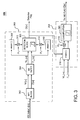
- FIG. 3 shows a more-detailed block diagram of MD/TA D&C subsystem 150 of FiGs. 1 and 2 .
- defect detector 202 of FIG. 2 includes discrete Fourier transform (DFT) block 302 , moving average (MA) filter 304 , mean generators 308 and 310, scalar multipliers 312 and 314 , and detection block 306
- defect classifier 204 of FIG. 2 includes mean generator 316 , scalar multiplier 318 , and classification block 320 .
- DFT discrete Fourier transform
- MA moving average
- M is an integer and T is the duration of one bit.
- M can have a value other than 2.
- DFT block 302 performs two different DFT functions in parallel on the ADC output samples x[n] to generate two different DFT output samples W[n] and Z[n], where DFT output sample W[n] corresponds to the M T data frequency and DFT output sample Z[n] corresponds to a data frequency different from the M T data frequency.
- DFT output sample W[ n ] is based on the 2T data frequency
- DFT output sample Z[n] is based on the DC (i.e., 0) data frequency as given by Equations (1) and (2) as follows:
- W n sqrt x ⁇ n - 4 - x ⁇ n - 2 + x n - x ⁇ n + 2 ⁇ ⁇ 2 + x ⁇ n - 3 - x ⁇ n - 1 + x ⁇ n + 1 - x ⁇ n + 3 ⁇ ⁇ 2
- Z n x ⁇ n - 4 + x ⁇ n - 3 + x ⁇ n - 2 + x ⁇ n - 1 + x n + x ⁇ n + 1 + x ⁇ n + 2 + x ⁇ n + 3 x ⁇ n + 3
- DFT output samples W[ n ] and Z[n] could alternatively be generated using sets of ADC output samples x[n] other than the set of eight samples shown in Equations (1) and (2), and these DFT samples may be computed using fewer or more than 8 samples.
- the DFT output sample Z[n] can be based on a data frequency other than the DC data frequency.
- FIG. 4 shows one possible hardware implementation of DFT block 302 of FIG. 3 . Note that, since Equations (1) and (2) use ADC output samples x[ i ] before and after sample x[n], the DFT output samples shown in FIG. 4 corresponding to input sample x[n] are W[ n -3] and Z[n-3].
- Mean generator 308 generates defect-free average W m,d according to Equation (6) as follows: W m , d ⁇ W m , d + ⁇ ⁇ W m n - W m , d where the local averages W m [ n ] used in Equation (6) correspond to defect-free regions.
- mean generator 310 generates defect-free average Z m , d according to Equation (7) as follows: Z m , d ⁇ Z m , d + ⁇ ⁇ Z m n - Z m , d where the local averages Z m [ n ] used in Equation (7) correspond to defect-free regions.
- defect-free averages W m,d and Z m,d are updated in Equations (6) and (7) only for normal (i.e., defect-free) regions of the hard disc.
- the weight factor ⁇ is set to a suitable value less than one and typically close to zero (e.g., ⁇ 0.1). In one implementation, the weight factor ⁇ is 0.05.
- the defect-free averages W m,d and Z m,d are initialized using suitable seed values, which are 400 and 10, respectively, in one possible implementation. Exact values for these and other parameters can be determined via simulation using data from actual hard drives.
- the updating of defect-free averages W m,d and Z m,d can be done once in 4 bits, resulting in a quarter-rate implementation compared to the full-rate implementation described in Equations (6) and (7) where updating is done every bit.
- Scalar multipliers 312 and 314 scale the defect-free averages W m,d and Z m,d by specified scale factors ⁇ 1 , and ⁇ 3 , respectively.
- the scale factors ⁇ 1 and ⁇ 3 are set to 0.5 and 5.0, respectively.
- the local average W m [n] for the 2T DFT component is substantially equal to the defect-free average W m , d for that component, and similarly the local average Z m [ n ] for the DC DFT component is substantially equal to the defect-free average Z m,d for that component.
- the local average W m [n] for the 2T DFT component is substantially equal to the defect-free average W m , d for that component.
- the local average W m [n] for the 2T DFT component will be substantially smaller than the defect-free average W m,d for that component, while the local average Z m [n] for the DC DFT component might or might not be substantially larger than the defect-free average Z m,d for that component.
- strength of DC DFT component will be larger than that for defect-free regions since occurrence of TA results in a readback signal with a broader spectrum compared to defect-free regions where the signal spectrum contains only the 2T frequency. As such, for a defect region, at least one inequality in Equation (8) will be satisfied.
- this MD/TA detector is used to process the signal from GMR heads where TA manifests as significant shift in signal baseline, then the second inequality in Equation (8) will be satisfied during defect regions containing GMR-TA, while the first inequality might or might not be satisfied.
- mean generator 316 of defect classifier 204 begins to generate defect averages W m,c and Z m,c according to Equations (9) and (10), respectively, as follows:
- W m , c W m n + W m ⁇ n + 1 + ⁇ + W m ⁇ n + L m - 1 Z m
- c n Z m n + Z m ⁇ n + 1 + ⁇ + Z m ⁇ n + L m - 1 where:
- the quantity L max may be set to a fixed length such as 64 or it can be set equal to the total defect length L d .
- Scalar multiplier 318 scales the defect average W m , c by specified scale factor ⁇ 2 .
- the scale factor ⁇ 2 is set to 0.2.
- the average W m , c for the 2T DFT component is larger than the average Z m , c for the DC DFT component, since the occurrence of drop-out type MD manifests predominantly as attenuation of the signal.
- the inequality in Equation (11) will be satisfied.
- the average W m,c for the 2T DFT component will be smaller than the average Z m,c for the DC DFT component because of the presence of the DC frequency component introduced by TA.
- the inequality in Equation (11) will not be satisfied.
- the 2T DFT component will be attenuated by the drop-out effect, and the DC DFT component will be enhanced, whereas, in GMR-TA regions, the DC DFT component is significantly enhanced by the strong baseline shift.
- MD/TA D&C subsystem 150 when the gap between the end of one defect region and the beginning of the next defect region is less than a specified distance apart, then the two defect regions and the intervening normal region are merged into one combined defect region for classification processing, where the combined defect region spans from the beginning of the first defect region until the end of the second defect region.
- the present invention may be implemented as (analog, digital, or a hybrid of both analog and digital) circuit-based processes, including possible implementation as a single integrated circuit (such as an ASIC or an FPGA), a multi-chip module, a single card, or a multi-card circuit pack.
- a single integrated circuit such as an ASIC or an FPGA
- a multi-chip module such as a single card, or a multi-card circuit pack.
- various functions of circuit elements may also be implemented as processing blocks in a software program.
- Such software may be employed in, for example, a digital signal processor, micro-controller, or general-purpose computer.
- the present invention can be embodied in the form of methods and apparatuses for practicing those methods.
- the present invention can also be embodied in the form of program code embodied in tangible media, such as magnetic recording media, optical recording media, solid state memory, floppy diskettes, CD-ROMs, hard drives, or any other machine-readable storage medium, wherein, when the program code is loaded into and executed by a machine, such as a computer, the machine becomes an apparatus for practicing the invention.
- the present invention can also be embodied in the form of program code, for example, whether stored in a storage medium or loaded into and/or executed by a machine, wherein, when the program code is loaded into and executed by a machine, such as a computer, the machine becomes an apparatus for practicing the invention.
- the program code segments combine with the processor to provide a unique device that operates analogously to specific logic circuits.
- figure numbers and/or figure reference labels in the claims is intended to identify one or more possible embodiments of the claimed subject matter in order to facilitate the interpretation of the claims. Such use is not to be construed as necessarily limiting the scope of those claims to the embodiments shown in the corresponding figures.
Landscapes
- Engineering & Computer Science (AREA)
- Signal Processing (AREA)
- Digital Magnetic Recording (AREA)
- Signal Processing For Digital Recording And Reproducing (AREA)
- Recording Or Reproducing By Magnetic Means (AREA)
- Manufacturing Of Magnetic Record Carriers (AREA)
- Optical Recording Or Reproduction (AREA)
Abstract
Description
- The subject matter of this application is related to the subject matter of
U.S. patent application no. 11/319,319 filed 12/28/05 andU.S. patent application no. 12/111,255 filed 04/29/08, the teachings of both of which are incorporated herein by reference in their entirety. - The present invention relates to hard-disc drives, and, in particular, to techniques for detecting defect regions in hard disc drives and classifying whether the defect regions correspond to thermal asperity or media defect.
- This section introduces aspects that may help facilitate a better understanding of the invention. Accordingly, the statements of this section are to be read in this light and are not to be understood as admissions about what is prior art or what is not prior art.
- An ideal hard disc of a hard-disc drive has a data-storage surface that is perfectly flat and of perfectly uniform material composition. In reality, however, hard discs are not perfectly flat and have varying material composition. As a result of this, as well as for manufacturing reasons, different types of defects can be present on hard discs. It can be difficult to recover data read from defect regions, and the intensity of difficulty depends on the type of defect. In drop-out type defect regions, the amplitude of the analog read-head output signal is significantly lower than the read-head output signal amplitude for normal regions that are relatively flat and of relatively uniform material composition. Data written on such defect regions may be recovered if the read-head output signal is appropriately amplified and conditioned by the electronics that processes the read-head output signal. In this document, we refer to such drop-out type defects as "media defects" (MD). It is desirable to determine the locations of MD regions on hard discs so that the signals read from those MD regions can be properly processed to recover the data accurately.
- Sometimes, the topography of a hard-disc region is so varied that the read head will come into physical contact with certain regions when the read head is positioned over these regions of the spinning hard disc due to the asperities present on the disc. Such regions are referred to as thermal asperity (TA) regions, due to the frictional heat generated from the physical contact between the read head and the varied hard disc. It is desirable to determine the locations of TA regions on hard discs so that those regions can be avoided during both data write and data read operations to prevent damage to the read head.
- Current and older hard-disc drives employed MR (magneto resistive) read heads or GMR (giant MR) read heads. For such read heads, read-head output signals corresponding to MD regions have amplitudes that are significantly smaller than the signal amplitudes for normal regions, while read-head output signals corresponding to TA regions have amplitudes that are significantly greater than the normal-region signal amplitudes due to a shift in baseline resulting from the TA effect. As such, MD regions can be located on a hard disc of a hard-disc drive employing an MR/GMR read head by looking for lower-than-normal signal-amplitude regions, while TA regions can be located on the hard disc by looking for significant increases in signal baseline compared to normal signal-amplitude regions.
- Newer hard-disc drives employ TMR (tunneling MR) read heads. For TMR read heads, TA regions can be mistaken for MD regions because read-head output signals corresponding to both MD regions and TA regions have amplitudes that are significantly smaller than the signal amplitudes for normal regions. As such, the conventional signal-processing techniques used to detect and classify MD and TA regions for hard-disc drives employing MR/GMR read heads cannot be used to detect and classify MD and TA regions for hard-disc drives employing TMR read heads.
- In one embodiment, the present invention is a machine-implemented method for detecting or classifying a defect region on a hard disc. Signal values are received corresponding to data stored on the hard disc in a data pattern having a first data frequency. A first measure is generated corresponding to the first data frequency, and a second measure is generated corresponding to a second data frequency different from the first data frequency. The defect region is detected or classified based on the first measure and the second measure.
- In another embodiment, the present invention is a read channel for a hard disc. The read channel comprises (1) analog circuitry adapted to generate an analog signal corresponding to data stored on the hard disc, (2) an analog-to-digital converter (ADC) adapted to convert the analog signal into a digital signal, and (3) digital circuitry adapted to generate recovered data from the digital signal. The digital circuitry comprises a processor adapted to (a) receive signal values corresponding to the data stored on the hard disc in a data pattern having a first data frequency, (b) generate a first measure corresponding to the first data frequency, (c) generate a second measure corresponding to a second data frequency different from the first data frequency, and (d) detect or classify a defect region on the hard disc based on the first measure and the second measure.
- Other aspects, features, and advantages of the present invention will become more fully apparent from the following detailed description, the appended claims, and the accompanying drawings in which like reference numerals identify similar or identical elements.
-
FIG. 1 shows a high-level block diagram of a read channel for a hard-disc drive employing a tunneling magneto resistive (TMR) read head, according to one embodiment of the present invention; -
FIG. 2 shows a high-level block diagram of the MD/TA detection and classification (D&C) subsystem ofFIG. 1 according to one possible implementation of the present invention; -
FIG. 3 shows a more-detailed block diagram of the MD/TA D&C subsystem ofFiGs. 1 and2 ; and -
FIG. 4 shows one possible hardware implementation of the DFT block ofFIG. 3 . -
FIG. 1 shows a high-level block diagram of a readchannel 100 for a hard-disc drive employing a tunneling magneto resistive (TMR) read head, according to one embodiment of the present invention. The (conventional) main signal-processing path of readchannel 100 receives analog read-head output signal 105 from the TMR read head (not shown) and outputs binary (hard-decision)output data signal 145. - As shown in
FIG. 1 , readchannel 100 includes pre-amplifier 110, analog front end (AFE) 120, analog-to-digital converter (ADC) 130, and digital back end (DBE) 140. Pre-amplifier 110 amplifies and conditions read-head output signal 105 to ensure that the signal amplitude and frequency components are within specified ranges for processing byAFE 120, which further amplifies and conditions thepre-amplified signal 115 from pre-amplifier 110.ADC 130 digitizes theAFE output signal 129 to produce multi-bit digital signal X (consisting of ADC output samples x[n]) for digital signal processing byDBE 140 that generates binaryoutput data signal 145. - As represented in
FIG. 1 , AFE 120 includes high-pass filter 122, variable-gain amplifier 124, magneto resistive asymmetry (MRA)compensation module 126, and continuous-time lowpass filter 128, while DBE 140 includes partial-response (PR)equalizer 142 and soft (e.g., Viterbi)detector 144. Of particular interest to the present invention,PR equalizer 142 receives digitized ADC output signal X fromADC 130 and generates multi-bit equalized signal Y (consisting of equalizer output samples y[n]), whichsoft detector 144 processes to generate binaryoutput data signal 145.PR equalizer 142 can be, but does not have to be, implemented as a digital finite impulse response (DFIR) filter. - In addition, TMR read
channel 100 includes media defect (MD) / thermal asperity (TA) detection andclassification subsystem 150, which receives and processessignal 147 from DBE 140 to detect the locations of defect regions on the hard disc and classify each detected defect region as being either an MD region or a TA region, which information is represented insignal 155. In one implementation,signal 147 is the ADC output signal X generated byADC 130. In another implementation,signal 147 is the equalized signal Y generated byPR equalizer 142. -
FIG. 2 shows a high-level block diagram of MD/TA detection and classification (D&C)subsystem 150 ofFIG. 1 according to one possible implementation of the present invention. In this particular implementation,D&C subsystem 150 processes ADC output samples x[n] of signal X ofFIG. 1 to detect and classify defect regions on a hard disc. In particular,D&C subsystem 150 includesdefect detector 202, which processes the ADC output samples x[n] to detect the location and duration of defect regions, anddefect classifier 204, which processes statistics generated bydefect detector 202 to classify each detected defect region as being either an MD region or a TA region. -
FIG. 3 shows a more-detailed block diagram of MD/TA D&C subsystem 150 ofFiGs. 1 and2 . As shown inFIG. 3 ,defect detector 202 ofFIG. 2 includes discrete Fourier transform (DFT)block 302, moving average (MA)filter 304,mean generators scalar multipliers detection block 306, whiledefect classifier 204 ofFIG. 2 includesmean generator 316,scalar multiplier 318, andclassification block 320. - To perform MD/TA detection and classification, data is written to the hard disc using a fixed MT data pattern having a period of 2MT, where M is an integer and T is the duration of one bit. For example, in one implementation, M=2 and the corresponding 2T data pattern (e.g., [11001100...]) having a period of 4T is written to the hard disc. In other implementations, M can have a value other than 2. DFT
block 302 performs two different DFT functions in parallel on the ADC output samples x[n] to generate two different DFT output samples W[n] and Z[n], where DFT output sample W[n] corresponds to the MT data frequency and DFT output sample Z[n] corresponds to a data frequency different from the MT data frequency. For example, in one possible implementation in which the hard-drive data has a 2T data pattern, DFT output sample W[n] is based on the 2T data frequency, and DFT output sample Z[n] is based on the DC (i.e., 0) data frequency as given by Equations (1) and (2) as follows:

- To simplify hardware implementation, in one possible implementation, the computation of 2T frequency DFT sample W[n] can be simplified as given by Equation (3) as follows:

- Those skilled in the art will understand that DFT output samples W[n] and Z[n] could alternatively be generated using sets of ADC output samples x[n] other than the set of eight samples shown in Equations (1) and (2), and these DFT samples may be computed using fewer or more than 8 samples. In addition, the DFT output sample Z[n] can be based on a data frequency other than the DC data frequency.
-
FIG. 4 shows one possible hardware implementation of DFT block 302 ofFIG. 3 . Note that, since Equations (1) and (2) use ADC output samples x[i] before and after sample x[n], the DFT output samples shown inFIG. 4 corresponding to input sample x[n] are W[n-3] and Z[n-3]. - Referring again to
FIG. 3 , moving average (MA)filter 304 generates local averages W m [n] and Zm[n] of the DFT output samples W[n] and Z[n] according to Equations (4) and (5), respectively, as follows:

where N i is a suitable number such as 4 or 8. Note that, for computational efficiency, local averages Wm[n] and Zm[n] are scaled averages because the sums are not divided by N1. -
Mean generator 308 generates defect-free average W m,d according to Equation (6) as follows:
where the local averages W m [n] used in Equation (6) correspond to defect-free regions. Similarly,mean generator 310 generates defect-free average Zm,d according to Equation (7) as follows:
where the local averages Z m [n] used in Equation (7) correspond to defect-free regions. Note that defect-free averages W m,d and Z m,d are updated in Equations (6) and (7) only for normal (i.e., defect-free) regions of the hard disc. The weight factor γ is set to a suitable value less than one and typically close to zero (e.g., <0.1). In one implementation, the weight factor γ is 0.05. The defect-free averages W m,d and Zm,d are initialized using suitable seed values, which are 400 and 10, respectively, in one possible implementation. Exact values for these and other parameters can be determined via simulation using data from actual hard drives. To support high-data-rate operation, the updating of defect-free averages Wm,d and Z m,d can be done once in 4 bits, resulting in a quarter-rate implementation compared to the full-rate implementation described in Equations (6) and (7) where updating is done every bit. -
Scalar multipliers - The resulting scaled, defect-free averages α1 Wm,d and α3Zm,d as well as the local averages Wm[n] and Zm[n] are applied to
detection block 306, which generates binary detection flag D[n] according to Equation (8) as follows:
where 0 < α1 < 1 and α3>1. In other words, if either of the two conditions specified in the first line of Equation (8) is true, then a defect region is detected (i.e., D[n]=1 ). Otherwise, if neither of those two conditions are satisfied, then a defect region is not detected (i.e., D[n]=0). In one implementation, the scale factors α1 and α3 are set to 0.5 and 5.0, respectively. - For normal (i.e., defect-free) regions, the local average Wm[n] for the 2T DFT component is substantially equal to the defect-free average Wm,d for that component, and similarly the local average Z m [n] for the DC DFT component is substantially equal to the defect-free average Z m,d for that component. As such, for a normal region, neither inequality in Equation (8) will be satisfied. On the other hand, for defect regions (i.e. MD regions or TMR-TA regions), the local average Wm[n] for the 2T DFT component will be substantially smaller than the defect-free average W m,d for that component, while the local average Zm[n] for the DC DFT component might or might not be substantially larger than the defect-free average Z m,d for that component. In defect regions corresponding to TMR-TA, strength of DC DFT component will be larger than that for defect-free regions since occurrence of TA results in a readback signal with a broader spectrum compared to defect-free regions where the signal spectrum contains only the 2T frequency. As such, for a defect region, at least one inequality in Equation (8) will be satisfied. Further, if this MD/TA detector is used to process the signal from GMR heads where TA manifests as significant shift in signal baseline, then the second inequality in Equation (8) will be satisfied during defect regions containing GMR-TA, while the first inequality might or might not be satisfied.
- When a defect region is detected by
detection block 306,mean generator 316 ofdefect classifier 204 begins to generate defect averages W m,c and Z m,c according to Equations (9) and (10), respectively, as follows:

where: - n is such that D[n+i]=1 for i=0,1,...,Lm-1,
- Lm = min {L d, Lmax } Lmax = 64, and
- Ld is the length of the detected defect in number of bits.
- Depending upon implementation ease, the quantity Lmax may be set to a fixed length such as 64 or it can be set equal to the total defect length Ld.
-
Scalar multiplier 318 scales the defect average Wm,c by specified scale factor α2.Classification block 320 generates binary classification flag C[n] according to Equation (11) as follows:
where 0 < α2 < 1. In particular, C=1 implies that the defect region is an MD region, and C=0 implies that the defect region is a TA region. In one implementation, the scale factor α2 is set to 0.2. - For MD regions, the average Wm,c for the 2T DFT component is larger than the average Z m,c for the DC DFT component, since the occurrence of drop-out type MD manifests predominantly as attenuation of the signal. As such, for an MD region, the inequality in Equation (11) will be satisfied. On the other hand, for TA regions, the average Wm,c for the 2T DFT component will be smaller than the average Z m,c for the DC DFT component because of the presence of the DC frequency component introduced by TA. As such, for a TA region, the inequality in Equation (11) will not be satisfied. In TMR-TA regions, the 2T DFT component will be attenuated by the drop-out effect, and the DC DFT component will be enhanced, whereas, in GMR-TA regions, the DC DFT component is significantly enhanced by the strong baseline shift.
- In one possible implementation of MD/
TA D&C subsystem 150, when the gap between the end of one defect region and the beginning of the next defect region is less than a specified distance apart, then the two defect regions and the intervening normal region are merged into one combined defect region for classification processing, where the combined defect region spans from the beginning of the first defect region until the end of the second defect region. - Although the present invention has been described in the context of a read channel for a TMR (tunneling magneto-resistive) read head, those skilled in the art will appreciate that the present invention can be implemented in the context of other types of read heads.
- Although the invention has been described in the context of DFT processing, the invention might be able to be implemented using other frequency-based transforms.
- The present invention may be implemented as (analog, digital, or a hybrid of both analog and digital) circuit-based processes, including possible implementation as a single integrated circuit (such as an ASIC or an FPGA), a multi-chip module, a single card, or a multi-card circuit pack. As would be apparent to one skilled in the art, various functions of circuit elements may also be implemented as processing blocks in a software program. Such software may be employed in, for example, a digital signal processor, micro-controller, or general-purpose computer.
- The present invention can be embodied in the form of methods and apparatuses for practicing those methods. The present invention can also be embodied in the form of program code embodied in tangible media, such as magnetic recording media, optical recording media, solid state memory, floppy diskettes, CD-ROMs, hard drives, or any other machine-readable storage medium, wherein, when the program code is loaded into and executed by a machine, such as a computer, the machine becomes an apparatus for practicing the invention. The present invention can also be embodied in the form of program code, for example, whether stored in a storage medium or loaded into and/or executed by a machine, wherein, when the program code is loaded into and executed by a machine, such as a computer, the machine becomes an apparatus for practicing the invention. When implemented on a general-purpose processor, the program code segments combine with the processor to provide a unique device that operates analogously to specific logic circuits.
- Unless explicitly stated otherwise, each numerical value and range should be interpreted as being approximate as if the word "about" or "approximately" preceded the value of the value or range.
- It will be further understood that various changes in the details, materials, and arrangements of the parts which have been described and illustrated in order to explain the nature of this invention may be made by those skilled in the art without departing from the scope of the invention as expressed in the following claims.
- The use of figure numbers and/or figure reference labels in the claims is intended to identify one or more possible embodiments of the claimed subject matter in order to facilitate the interpretation of the claims. Such use is not to be construed as necessarily limiting the scope of those claims to the embodiments shown in the corresponding figures.
- It should be understood that the steps of the exemplary methods set forth herein are not necessarily required to be performed in the order described, and the order of the steps of such methods should be understood to be merely exemplary. Likewise, additional steps may be included in such methods, and certain steps may be omitted or combined, in methods consistent with various embodiments of the present invention.
- Although the elements in the following claims, if any, are recited in a particular sequence with corresponding labeling, unless the claim recitations otherwise imply a particular sequence for implementing some or all of those elements, those elements are not necessarily intended to be limited to being implemented in that particular sequence.
- Reference herein to "one embodiment" or "an embodiment" means that a particular feature, structure, or characteristic described in connection with the embodiment can be included in at least one embodiment of the invention. The appearances of the phrase "in one embodiment" in various places in the specification are not necessarily all referring to the same embodiment, nor are separate or alternative embodiments necessarily mutually exclusive of other embodiments. The same applies to the term "implementation."
Claims (15)
- A machine-implemented method for detecting or classifying a defect region on a hard disc, the method comprising:(a) receiving signal values (e.g., x[n], y[n]) corresponding to data stored on the hard disc in a data pattern having a first data frequency;(b) generating a first measure (e.g., W[n]) corresponding to the first data frequency;(c) generating a second measure (e.g., Z[n]) corresponding to a second data frequency different from the first data frequency; and(d) detecting or classifying the defect region based on the first measure and the second measure.
- The invention of claim 1, wherein the signal values are analog-to-digital converter (ADC) output signal values generated by an ADC of a read channel associated with the hard disc.
- The invention of claim 1, wherein the signal values are equalizer output signal values generated by an equalizer of a read channel associated with the hard disc.
- The invention of claim 1, wherein:the first measure is a first discrete Fourier transform (DFT) measure at the first data frequency; andthe second measure is a second DFT measure at the second data frequency.
- The invention of claim 1, wherein the second data frequency is a DC data frequency.
- The invention of claim 1, wherein the first data frequency is a 2T data frequency.
- The invention of claim 1, wherein step (d) comprises detecting location of the defect region on the hard disc based on the first measure and the second measure.
- The invention of claim 7, wherein step (d) further comprises classifying the defect region on the hard disc as being associated with thermal asperity (TA) or drop-out media defect (MD) based on the first measure and the second measure.
- The invention of claim 7, wherein:step (b) comprises generating (i) a first average strength value (e.g., X m [n]) of a first-data-frequency component of the signal values corresponding to the defect region and (ii) a second average strength value (e.g., X m,d ) of the first-data-frequency component corresponding to one or more defect-free regions on the hard disc;step (c) comprises generating (i) a first average strength value (e.g., Z m [n]) of a second-data-frequency component of the signal values corresponding to the defect region and (ii) a second average strength value (e.g., Z m,d ) of the second-data-frequency component corresponding to one or more defect-free regions on the hard disc; andstep (d) comprises:(d1) comparing the first and second average strength values of the first-data-frequency component;(d2) comparing the first and second average strength values of the second-data-frequency component; and(d3) detecting the location of the defect region on the hard disc based on the comparisons of steps (d1) and (d2).
- The invention of claim 9, wherein step (d3) comprises detecting the location of the defect region on the hard disc if either the comparison of step (d1) or the comparison of step (d2) is true.
- The invention of claim 9, wherein:step (d1) comprises determining whether the first average strength value of the first-data-frequency component is less than a specified first fraction (e.g., α1) of the second average strength value of the first-data-frequency component, wherein the specified first fraction is less than one; andstep (d2) comprises determining whether the first average strength value of the second-data-frequency component is greater than a specified second fraction (e.g., α3) of the second average strength value of the second-data-frequency component, wherein the specified second fraction is less than one.
- The invention of claim 1, wherein step (d) comprises classifying the defect region on the hard disc as being associated with thermal asperity (TA) or drop-out media defect (MD) based on the first measure and the second measure.
- The invention of claim 12, wherein:step (b) comprises generating an average strength value (e.g., X m,c) of a first-data-frequency component of the signal values corresponding to the defect region;step (c) comprises generating an average strength value (e.g., Z m,c ) of a second-data-frequency component of the signal values corresponding to the defect region; andstep (d) comprises:(d1) comparing the average strength value of the first-data-frequency component
and the average strength value of the second-data-frequency component; and (d2) classifying the defect region on the hard disc as being associated with TA or
MD based on the comparison of step (d1). - The invention of claim 13, wherein:step (d1) comprises determining whether the average strength value of the first-data-frequency component is less than a specified fraction (e.g., α2) of the average strength value of the second-data-frequency component, wherein the specified fraction is less than one.
- Apparatus for detecting or classifying a defect region on a hard disc, the apparatus comprising:(a) means for receiving signal values (e.g., x[n], y[n]) corresponding to data stored on the hard disc in a data pattern having a first data frequency;(b) means for generating a first measure corresponding to the first data frequency;(c) means for generating a second measure corresponding to a second data frequency different from the first data frequency; and(d) means for detecting or classifying the defect region based on the first measure and the second measure.
Applications Claiming Priority (1)
| Application Number | Priority Date | Filing Date | Title |
|---|---|---|---|
| US12/707,820 US8031420B2 (en) | 2010-02-18 | 2010-02-18 | Frequency-based approach for detection and classification of hard-disc defect regions |
Publications (3)
| Publication Number | Publication Date |
|---|---|
| EP2362395A2 true EP2362395A2 (en) | 2011-08-31 |
| EP2362395A3 EP2362395A3 (en) | 2012-01-11 |
| EP2362395B1 EP2362395B1 (en) | 2014-09-10 |
Family
ID=43770578
Family Applications (1)
| Application Number | Title | Priority Date | Filing Date |
|---|---|---|---|
| EP11000843.0A Active EP2362395B1 (en) | 2010-02-18 | 2011-02-03 | Frequency-based approach for detection and classification of hard-disc defect regions |
Country Status (6)
| Country | Link |
|---|---|
| US (1) | US8031420B2 (en) |
| EP (1) | EP2362395B1 (en) |
| JP (1) | JP5055447B2 (en) |
| KR (1) | KR101304187B1 (en) |
| CN (1) | CN102163460B (en) |
| TW (1) | TWI433138B (en) |
Cited By (1)
| Publication number | Priority date | Publication date | Assignee | Title |
|---|---|---|---|---|
| EP2733702A1 (en) * | 2012-11-19 | 2014-05-21 | LSI Corporation | System and method for classifying media defects based on a ratio of harmonics |
Families Citing this family (9)
| Publication number | Priority date | Publication date | Assignee | Title |
|---|---|---|---|---|
| US8654464B2 (en) * | 2011-10-19 | 2014-02-18 | HGST Netherlands B.V. | Implementing magnetic defect classification using phase modulation |
| US8675297B2 (en) * | 2012-06-15 | 2014-03-18 | Lsi Corporation | Media defect classification |
| US8824087B2 (en) * | 2012-08-02 | 2014-09-02 | Lsi Corporation | Zero gain start bias estimation |
| US8797667B1 (en) | 2012-10-15 | 2014-08-05 | Western Digital Technologies, Inc. | Disk drive calibrating bias signal for touchdown sensor |
| US8941941B1 (en) | 2013-02-28 | 2015-01-27 | Western Digital Technologies, Inc. | Disk drive calibrating touchdown sensor |
| US8964321B2 (en) | 2013-05-31 | 2015-02-24 | International Business Machines Corporation | Iterative data storage read channel architecture having dropout mitigation |
| US8988798B2 (en) | 2013-05-31 | 2015-03-24 | International Business Machines Corporation | Iterative data storage read channel architecture |
| US9214187B2 (en) | 2013-05-31 | 2015-12-15 | International Business Machines Corporation | Cycle-slip resilient iterative data storage read channel architecture |
| US8902533B1 (en) | 2013-08-30 | 2014-12-02 | Western Digital Technologies, Inc. | Disk drive detecting different asperities on a disk using different sensor bias settings |
Citations (1)
| Publication number | Priority date | Publication date | Assignee | Title |
|---|---|---|---|---|
| US11125508B2 (en) | 2014-11-12 | 2021-09-21 | Asia Vital Components Co., Ltd. | Thin heat pipe structure |
Family Cites Families (21)
| Publication number | Priority date | Publication date | Assignee | Title |
|---|---|---|---|---|
| KR100208383B1 (en) * | 1997-06-03 | 1999-07-15 | 윤종용 | Capacity conversion production method of hard disk drive |
| JP3349934B2 (en) | 1997-12-01 | 2002-11-25 | 富士通株式会社 | Magnetic disk device and read channel IC used for this device |
| US6791778B2 (en) | 2000-09-14 | 2004-09-14 | Samsung Electronics Co., Inc. | Method and apparatus to detect and manage servo sectors with defect on servo pattern area in hard disk drives |
| US6414806B1 (en) * | 2000-10-02 | 2002-07-02 | International Business Machines Corporation | Method for thermal asperity detection and compensation in disk drive channels |
| US6665134B2 (en) * | 2001-06-01 | 2003-12-16 | International Business Machines Corporation | Methods and apparatus for detection and analysis of an envelope of a frequency modulated readback signal in a magnetic storage system |
| US6671111B2 (en) * | 2001-06-01 | 2003-12-30 | International Business Machines Corporation | Readback signal detection and analysis in a magnetic data storage system |
| JP4198904B2 (en) * | 2001-06-11 | 2008-12-17 | 富士通株式会社 | Recording / reproducing apparatus, signal decoding circuit, error correcting method, and iterative decoder |
| US7271967B2 (en) * | 2004-10-28 | 2007-09-18 | Hitachi Global Storage Technologies Netherlands B.V. | System and method for determining whether defect in perpendicular recording disk drive is from thermal asperity or defect in magnetically soft underlayer |
| US7646556B1 (en) * | 2005-07-08 | 2010-01-12 | Seagate Technology Llc | Systems and methods for detecting flaws on a storage disk |
| JP4763438B2 (en) | 2005-12-01 | 2011-08-31 | ヒタチグローバルストレージテクノロジーズネザーランドビーブイ | Magnetic disk device, defective sector registration method, and flying height control method |
| US7679853B2 (en) * | 2005-12-28 | 2010-03-16 | Agere Systems Inc. | Detection of signal disturbance in a partial response channel |
| JP2007234113A (en) * | 2006-02-28 | 2007-09-13 | Fujitsu Ltd | Disk device and disk device control method |
| JP4652310B2 (en) * | 2006-10-31 | 2011-03-16 | 富士通株式会社 | Decoder and reproducing apparatus |
| JP2008112516A (en) * | 2006-10-31 | 2008-05-15 | Fujitsu Ltd | Error correction circuit and information reproducing apparatus |
| KR20080083523A (en) * | 2007-03-12 | 2008-09-18 | 삼성전자주식회사 | Defect inspection method of recording media and disk drive using same |
| US20080262643A1 (en) * | 2007-04-17 | 2008-10-23 | Broadcom Corporation, A California Corporation | Defect detector for hard disk drive and methods for use therewith |
| US8161357B2 (en) * | 2008-03-17 | 2012-04-17 | Agere Systems Inc. | Systems and methods for using intrinsic data for regenerating data from a defective medium |
| US8121224B2 (en) * | 2008-04-29 | 2012-02-21 | Agere Systems Inc. | Systems and methods for filter based media defect detection |
| US7849385B2 (en) * | 2008-04-29 | 2010-12-07 | Agere Systems Inc. | Systems and methods for media defect detection utilizing correlated DFIR and LLR data |
| JP4836282B2 (en) * | 2008-06-12 | 2011-12-14 | 東芝ストレージデバイス株式会社 | Head flying height adjustment method, write current value determination method, and storage device |
| US8219892B2 (en) | 2009-03-06 | 2012-07-10 | Agere Systems Inc. | Systems and methods for enhanced media defect detection |
-
2010
- 2010-02-18 US US12/707,820 patent/US8031420B2/en active Active
-
2011
- 2011-02-03 EP EP11000843.0A patent/EP2362395B1/en active Active
- 2011-02-16 KR KR1020110013586A patent/KR101304187B1/en not_active Expired - Fee Related
- 2011-02-17 CN CN201110040916.6A patent/CN102163460B/en active Active
- 2011-02-18 JP JP2011032708A patent/JP5055447B2/en not_active Expired - Fee Related
- 2011-02-18 TW TW100105513A patent/TWI433138B/en not_active IP Right Cessation
Patent Citations (1)
| Publication number | Priority date | Publication date | Assignee | Title |
|---|---|---|---|---|
| US11125508B2 (en) | 2014-11-12 | 2021-09-21 | Asia Vital Components Co., Ltd. | Thin heat pipe structure |
Cited By (2)
| Publication number | Priority date | Publication date | Assignee | Title |
|---|---|---|---|---|
| EP2733702A1 (en) * | 2012-11-19 | 2014-05-21 | LSI Corporation | System and method for classifying media defects based on a ratio of harmonics |
| US8811136B2 (en) | 2012-11-19 | 2014-08-19 | Lsi Corporation | Harmonic ratio based defect classifier |
Also Published As
| Publication number | Publication date |
|---|---|
| TW201142833A (en) | 2011-12-01 |
| JP2011170957A (en) | 2011-09-01 |
| US20110199699A1 (en) | 2011-08-18 |
| US8031420B2 (en) | 2011-10-04 |
| CN102163460A (en) | 2011-08-24 |
| EP2362395B1 (en) | 2014-09-10 |
| KR101304187B1 (en) | 2013-09-06 |
| CN102163460B (en) | 2014-04-02 |
| TWI433138B (en) | 2014-04-01 |
| EP2362395A3 (en) | 2012-01-11 |
| KR20110095179A (en) | 2011-08-24 |
| JP5055447B2 (en) | 2012-10-24 |
Similar Documents
| Publication | Publication Date | Title |
|---|---|---|
| EP2362395B1 (en) | Frequency-based approach for detection and classification of hard-disc defect regions | |
| US6731442B2 (en) | Method and apparatus for detecting media defects | |
| JP3723651B2 (en) | Method and apparatus for restoring the thermal response of a magnetoresistive head | |
| TWI433142B (en) | Method and apparatus for controlling fly-height of a head | |
| EP2369585A1 (en) | Amplitude-based approach for detection and classification of hard-disc defect regions | |
| US8683277B1 (en) | Defect detection using pattern matching on detected data | |
| US6175460B1 (en) | Magnetic recording and reproduction apparatus | |
| EP2372714A2 (en) | Detection of hard-disc defect regions using soft decisions | |
| Yeh et al. | Optimal head design and characterization from a media perspective | |
| KR100468773B1 (en) | System and method for magneto-resistive head electrostatic popping detection | |
| US8675297B2 (en) | Media defect classification | |
| US8654464B2 (en) | Implementing magnetic defect classification using phase modulation | |
| CN103824575B (en) | Defect grader based on harmonic wave ratio | |
| US7529049B2 (en) | Method and system for testing of magnetic disks using F-BER | |
| JP2008171507A (en) | Inspection method and inspection apparatus for perpendicular magnetic recording medium | |
| Valcu et al. | Correlation of signal and SNR thermal decay | |
| JP2005018826A (en) | Inspection method for vertical magnetic recording disk and hard disk drive | |
| JP2008090972A (en) | Characteristic evaluation method and characteristic evaluation apparatus for magnetic head | |
| JP2002312913A (en) | Inspection apparatus and inspection method for magnetoresistive element | |
| JP2006228385A (en) | Magnetic recording medium evaluation method and apparatus | |
| JPH06295407A (en) | Evaluation method for characteristic of peak shift distribution for digital magnetic recording |
Legal Events
| Date | Code | Title | Description |
|---|---|---|---|
| PUAI | Public reference made under article 153(3) epc to a published international application that has entered the european phase |
Free format text: ORIGINAL CODE: 0009012 |
|
| AK | Designated contracting states |
Kind code of ref document: A2 Designated state(s): AL AT BE BG CH CY CZ DE DK EE ES FI FR GB GR HR HU IE IS IT LI LT LU LV MC MK MT NL NO PL PT RO RS SE SI SK SM TR |
|
| AX | Request for extension of the european patent |
Extension state: BA ME |
|
| PUAL | Search report despatched |
Free format text: ORIGINAL CODE: 0009013 |
|
| AK | Designated contracting states |
Kind code of ref document: A3 Designated state(s): AL AT BE BG CH CY CZ DE DK EE ES FI FR GB GR HR HU IE IS IT LI LT LU LV MC MK MT NL NO PL PT RO RS SE SI SK SM TR |
|
| AX | Request for extension of the european patent |
Extension state: BA ME |
|
| RIC1 | Information provided on ipc code assigned before grant |
Ipc: G11B 19/04 20060101ALI20111206BHEP Ipc: G11B 20/18 20060101AFI20111206BHEP Ipc: G11B 5/012 20060101ALI20111206BHEP Ipc: G11B 27/36 20060101ALI20111206BHEP |
|
| 17P | Request for examination filed |
Effective date: 20120711 |
|
| GRAP | Despatch of communication of intention to grant a patent |
Free format text: ORIGINAL CODE: EPIDOSNIGR1 |
|
| INTG | Intention to grant announced |
Effective date: 20140513 |
|
| GRAS | Grant fee paid |
Free format text: ORIGINAL CODE: EPIDOSNIGR3 |
|
| GRAA | (expected) grant |
Free format text: ORIGINAL CODE: 0009210 |
|
| AK | Designated contracting states |
Kind code of ref document: B1 Designated state(s): AL AT BE BG CH CY CZ DE DK EE ES FI FR GB GR HR HU IE IS IT LI LT LU LV MC MK MT NL NO PL PT RO RS SE SI SK SM TR |
|
| REG | Reference to a national code |
Ref country code: GB Ref legal event code: FG4D |
|
| REG | Reference to a national code |
Ref country code: CH Ref legal event code: EP |
|
| REG | Reference to a national code |
Ref country code: IE Ref legal event code: FG4D |
|
| REG | Reference to a national code |
Ref country code: AT Ref legal event code: REF Ref document number: 687048 Country of ref document: AT Kind code of ref document: T Effective date: 20141015 |
|
| REG | Reference to a national code |
Ref country code: DE Ref legal event code: R096 Ref document number: 602011009726 Country of ref document: DE Effective date: 20141023 |
|
| PG25 | Lapsed in a contracting state [announced via postgrant information from national office to epo] |
Ref country code: NO Free format text: LAPSE BECAUSE OF FAILURE TO SUBMIT A TRANSLATION OF THE DESCRIPTION OR TO PAY THE FEE WITHIN THE PRESCRIBED TIME-LIMIT Effective date: 20141210 Ref country code: SE Free format text: LAPSE BECAUSE OF FAILURE TO SUBMIT A TRANSLATION OF THE DESCRIPTION OR TO PAY THE FEE WITHIN THE PRESCRIBED TIME-LIMIT Effective date: 20140910 Ref country code: ES Free format text: LAPSE BECAUSE OF FAILURE TO SUBMIT A TRANSLATION OF THE DESCRIPTION OR TO PAY THE FEE WITHIN THE PRESCRIBED TIME-LIMIT Effective date: 20140910 Ref country code: LT Free format text: LAPSE BECAUSE OF FAILURE TO SUBMIT A TRANSLATION OF THE DESCRIPTION OR TO PAY THE FEE WITHIN THE PRESCRIBED TIME-LIMIT Effective date: 20140910 Ref country code: FI Free format text: LAPSE BECAUSE OF FAILURE TO SUBMIT A TRANSLATION OF THE DESCRIPTION OR TO PAY THE FEE WITHIN THE PRESCRIBED TIME-LIMIT Effective date: 20140910 Ref country code: GR Free format text: LAPSE BECAUSE OF FAILURE TO SUBMIT A TRANSLATION OF THE DESCRIPTION OR TO PAY THE FEE WITHIN THE PRESCRIBED TIME-LIMIT Effective date: 20141211 |
|
| REG | Reference to a national code |
Ref country code: NL Ref legal event code: VDEP Effective date: 20140910 |
|
| REG | Reference to a national code |
Ref country code: LT Ref legal event code: MG4D |
|
| PG25 | Lapsed in a contracting state [announced via postgrant information from national office to epo] |
Ref country code: LV Free format text: LAPSE BECAUSE OF FAILURE TO SUBMIT A TRANSLATION OF THE DESCRIPTION OR TO PAY THE FEE WITHIN THE PRESCRIBED TIME-LIMIT Effective date: 20140910 Ref country code: RS Free format text: LAPSE BECAUSE OF FAILURE TO SUBMIT A TRANSLATION OF THE DESCRIPTION OR TO PAY THE FEE WITHIN THE PRESCRIBED TIME-LIMIT Effective date: 20140910 Ref country code: CY Free format text: LAPSE BECAUSE OF FAILURE TO SUBMIT A TRANSLATION OF THE DESCRIPTION OR TO PAY THE FEE WITHIN THE PRESCRIBED TIME-LIMIT Effective date: 20140910 Ref country code: HR Free format text: LAPSE BECAUSE OF FAILURE TO SUBMIT A TRANSLATION OF THE DESCRIPTION OR TO PAY THE FEE WITHIN THE PRESCRIBED TIME-LIMIT Effective date: 20140910 |
|
| REG | Reference to a national code |
Ref country code: AT Ref legal event code: MK05 Ref document number: 687048 Country of ref document: AT Kind code of ref document: T Effective date: 20140910 |
|
| PG25 | Lapsed in a contracting state [announced via postgrant information from national office to epo] |
Ref country code: NL Free format text: LAPSE BECAUSE OF FAILURE TO SUBMIT A TRANSLATION OF THE DESCRIPTION OR TO PAY THE FEE WITHIN THE PRESCRIBED TIME-LIMIT Effective date: 20140910 |
|
| PG25 | Lapsed in a contracting state [announced via postgrant information from national office to epo] |
Ref country code: CZ Free format text: LAPSE BECAUSE OF FAILURE TO SUBMIT A TRANSLATION OF THE DESCRIPTION OR TO PAY THE FEE WITHIN THE PRESCRIBED TIME-LIMIT Effective date: 20140910 Ref country code: IS Free format text: LAPSE BECAUSE OF FAILURE TO SUBMIT A TRANSLATION OF THE DESCRIPTION OR TO PAY THE FEE WITHIN THE PRESCRIBED TIME-LIMIT Effective date: 20150110 Ref country code: EE Free format text: LAPSE BECAUSE OF FAILURE TO SUBMIT A TRANSLATION OF THE DESCRIPTION OR TO PAY THE FEE WITHIN THE PRESCRIBED TIME-LIMIT Effective date: 20140910 Ref country code: SK Free format text: LAPSE BECAUSE OF FAILURE TO SUBMIT A TRANSLATION OF THE DESCRIPTION OR TO PAY THE FEE WITHIN THE PRESCRIBED TIME-LIMIT Effective date: 20140910 Ref country code: PT Free format text: LAPSE BECAUSE OF FAILURE TO SUBMIT A TRANSLATION OF THE DESCRIPTION OR TO PAY THE FEE WITHIN THE PRESCRIBED TIME-LIMIT Effective date: 20150112 Ref country code: RO Free format text: LAPSE BECAUSE OF FAILURE TO SUBMIT A TRANSLATION OF THE DESCRIPTION OR TO PAY THE FEE WITHIN THE PRESCRIBED TIME-LIMIT Effective date: 20140910 |
|
| PG25 | Lapsed in a contracting state [announced via postgrant information from national office to epo] |
Ref country code: AT Free format text: LAPSE BECAUSE OF FAILURE TO SUBMIT A TRANSLATION OF THE DESCRIPTION OR TO PAY THE FEE WITHIN THE PRESCRIBED TIME-LIMIT Effective date: 20140910 Ref country code: PL Free format text: LAPSE BECAUSE OF FAILURE TO SUBMIT A TRANSLATION OF THE DESCRIPTION OR TO PAY THE FEE WITHIN THE PRESCRIBED TIME-LIMIT Effective date: 20140910 |
|
| REG | Reference to a national code |
Ref country code: DE Ref legal event code: R097 Ref document number: 602011009726 Country of ref document: DE |
|
| PG25 | Lapsed in a contracting state [announced via postgrant information from national office to epo] |
Ref country code: BE Free format text: LAPSE BECAUSE OF NON-PAYMENT OF DUE FEES Effective date: 20150228 |
|
| PLBE | No opposition filed within time limit |
Free format text: ORIGINAL CODE: 0009261 |
|
| STAA | Information on the status of an ep patent application or granted ep patent |
Free format text: STATUS: NO OPPOSITION FILED WITHIN TIME LIMIT |
|
| PG25 | Lapsed in a contracting state [announced via postgrant information from national office to epo] |
Ref country code: DK Free format text: LAPSE BECAUSE OF FAILURE TO SUBMIT A TRANSLATION OF THE DESCRIPTION OR TO PAY THE FEE WITHIN THE PRESCRIBED TIME-LIMIT Effective date: 20140910 |
|
| 26N | No opposition filed |
Effective date: 20150611 |
|
| PG25 | Lapsed in a contracting state [announced via postgrant information from national office to epo] |
Ref country code: IT Free format text: LAPSE BECAUSE OF FAILURE TO SUBMIT A TRANSLATION OF THE DESCRIPTION OR TO PAY THE FEE WITHIN THE PRESCRIBED TIME-LIMIT Effective date: 20140910 |
|
| PG25 | Lapsed in a contracting state [announced via postgrant information from national office to epo] |
Ref country code: LU Free format text: LAPSE BECAUSE OF FAILURE TO SUBMIT A TRANSLATION OF THE DESCRIPTION OR TO PAY THE FEE WITHIN THE PRESCRIBED TIME-LIMIT Effective date: 20150203 |
|
| REG | Reference to a national code |
Ref country code: CH Ref legal event code: PL |
|
| GBPC | Gb: european patent ceased through non-payment of renewal fee |
Effective date: 20150203 |
|
| PG25 | Lapsed in a contracting state [announced via postgrant information from national office to epo] |
Ref country code: CH Free format text: LAPSE BECAUSE OF NON-PAYMENT OF DUE FEES Effective date: 20150228 Ref country code: MC Free format text: LAPSE BECAUSE OF FAILURE TO SUBMIT A TRANSLATION OF THE DESCRIPTION OR TO PAY THE FEE WITHIN THE PRESCRIBED TIME-LIMIT Effective date: 20140910 Ref country code: LI Free format text: LAPSE BECAUSE OF NON-PAYMENT OF DUE FEES Effective date: 20150228 |
|
| REG | Reference to a national code |
Ref country code: IE Ref legal event code: MM4A |
|
| REG | Reference to a national code |
Ref country code: FR Ref legal event code: ST Effective date: 20151030 |
|
| PG25 | Lapsed in a contracting state [announced via postgrant information from national office to epo] |
Ref country code: SI Free format text: LAPSE BECAUSE OF FAILURE TO SUBMIT A TRANSLATION OF THE DESCRIPTION OR TO PAY THE FEE WITHIN THE PRESCRIBED TIME-LIMIT Effective date: 20140910 |
|
| PG25 | Lapsed in a contracting state [announced via postgrant information from national office to epo] |
Ref country code: GB Free format text: LAPSE BECAUSE OF NON-PAYMENT OF DUE FEES Effective date: 20150203 Ref country code: IE Free format text: LAPSE BECAUSE OF NON-PAYMENT OF DUE FEES Effective date: 20150203 |
|
| PG25 | Lapsed in a contracting state [announced via postgrant information from national office to epo] |
Ref country code: FR Free format text: LAPSE BECAUSE OF NON-PAYMENT OF DUE FEES Effective date: 20150302 |
|
| PG25 | Lapsed in a contracting state [announced via postgrant information from national office to epo] |
Ref country code: BE Free format text: LAPSE BECAUSE OF FAILURE TO SUBMIT A TRANSLATION OF THE DESCRIPTION OR TO PAY THE FEE WITHIN THE PRESCRIBED TIME-LIMIT Effective date: 20140910 |
|
| PG25 | Lapsed in a contracting state [announced via postgrant information from national office to epo] |
Ref country code: MT Free format text: LAPSE BECAUSE OF FAILURE TO SUBMIT A TRANSLATION OF THE DESCRIPTION OR TO PAY THE FEE WITHIN THE PRESCRIBED TIME-LIMIT Effective date: 20140910 |
|
| PG25 | Lapsed in a contracting state [announced via postgrant information from national office to epo] |
Ref country code: BG Free format text: LAPSE BECAUSE OF FAILURE TO SUBMIT A TRANSLATION OF THE DESCRIPTION OR TO PAY THE FEE WITHIN THE PRESCRIBED TIME-LIMIT Effective date: 20140910 Ref country code: HU Free format text: LAPSE BECAUSE OF FAILURE TO SUBMIT A TRANSLATION OF THE DESCRIPTION OR TO PAY THE FEE WITHIN THE PRESCRIBED TIME-LIMIT; INVALID AB INITIO Effective date: 20110203 Ref country code: SM Free format text: LAPSE BECAUSE OF FAILURE TO SUBMIT A TRANSLATION OF THE DESCRIPTION OR TO PAY THE FEE WITHIN THE PRESCRIBED TIME-LIMIT Effective date: 20140910 |
|
| PG25 | Lapsed in a contracting state [announced via postgrant information from national office to epo] |
Ref country code: TR Free format text: LAPSE BECAUSE OF FAILURE TO SUBMIT A TRANSLATION OF THE DESCRIPTION OR TO PAY THE FEE WITHIN THE PRESCRIBED TIME-LIMIT Effective date: 20140910 |
|
| PG25 | Lapsed in a contracting state [announced via postgrant information from national office to epo] |
Ref country code: MK Free format text: LAPSE BECAUSE OF FAILURE TO SUBMIT A TRANSLATION OF THE DESCRIPTION OR TO PAY THE FEE WITHIN THE PRESCRIBED TIME-LIMIT Effective date: 20140910 |
|
| PG25 | Lapsed in a contracting state [announced via postgrant information from national office to epo] |
Ref country code: AL Free format text: LAPSE BECAUSE OF FAILURE TO SUBMIT A TRANSLATION OF THE DESCRIPTION OR TO PAY THE FEE WITHIN THE PRESCRIBED TIME-LIMIT Effective date: 20140910 |
|
| REG | Reference to a national code |
Ref country code: DE Ref legal event code: R082 Ref document number: 602011009726 Country of ref document: DE Representative=s name: DILG, HAEUSLER, SCHINDELMANN PATENTANWALTSGESE, DE Ref country code: DE Ref legal event code: R081 Ref document number: 602011009726 Country of ref document: DE Owner name: BROADCOM INTERNATIONAL PTE. LTD., SG Free format text: FORMER OWNER: LSI CORP., MILPITAS, CALIF., US Ref country code: DE Ref legal event code: R082 Ref document number: 602011009726 Country of ref document: DE Representative=s name: DILG HAEUSLER SCHINDELMANN PATENTANWALTSGESELL, DE Ref country code: DE Ref legal event code: R081 Ref document number: 602011009726 Country of ref document: DE Owner name: AVAGO TECHNOLOGIES GENERAL IP (SINGAPORE) PTE., SG Free format text: FORMER OWNER: LSI CORP., MILPITAS, CALIF., US Ref country code: DE Ref legal event code: R081 Ref document number: 602011009726 Country of ref document: DE Owner name: AVAGO TECHNOLOGIES INTERNATIONAL SALES PTE. LT, SG Free format text: FORMER OWNER: LSI CORP., MILPITAS, CALIF., US |
|
| REG | Reference to a national code |
Ref country code: DE Ref legal event code: R081 Ref document number: 602011009726 Country of ref document: DE Owner name: AVAGO TECHNOLOGIES INTERNATIONAL SALES PTE. LI, SG Free format text: FORMER OWNER: AVAGO TECHNOLOGIES GENERAL IP (SINGAPORE) PTE. LTD., SINGAPUR, SG Ref country code: DE Ref legal event code: R082 Ref document number: 602011009726 Country of ref document: DE Representative=s name: DILG, HAEUSLER, SCHINDELMANN PATENTANWALTSGESE, DE Ref country code: DE Ref legal event code: R081 Ref document number: 602011009726 Country of ref document: DE Owner name: BROADCOM INTERNATIONAL PTE. LTD., SG Free format text: FORMER OWNER: AVAGO TECHNOLOGIES GENERAL IP (SINGAPORE) PTE. LTD., SINGAPUR, SG Ref country code: DE Ref legal event code: R082 Ref document number: 602011009726 Country of ref document: DE Representative=s name: DILG HAEUSLER SCHINDELMANN PATENTANWALTSGESELL, DE Ref country code: DE Ref legal event code: R081 Ref document number: 602011009726 Country of ref document: DE Owner name: AVAGO TECHNOLOGIES INTERNATIONAL SALES PTE. LT, SG Free format text: FORMER OWNER: AVAGO TECHNOLOGIES GENERAL IP (SINGAPORE) PTE. LTD., SINGAPUR, SG |
|
| REG | Reference to a national code |
Ref country code: DE Ref legal event code: R081 Ref document number: 602011009726 Country of ref document: DE Owner name: AVAGO TECHNOLOGIES INTERNATIONAL SALES PTE. LI, SG Free format text: FORMER OWNER: AVAGO TECHNOLOGIES INTERNATIONAL SALES PTE. LTD., SINGAPUR, SG Ref country code: DE Ref legal event code: R082 Ref document number: 602011009726 Country of ref document: DE Representative=s name: DILG, HAEUSLER, SCHINDELMANN PATENTANWALTSGESE, DE Ref country code: DE Ref legal event code: R081 Ref document number: 602011009726 Country of ref document: DE Owner name: BROADCOM INTERNATIONAL PTE. LTD., SG Free format text: FORMER OWNER: AVAGO TECHNOLOGIES INTERNATIONAL SALES PTE. LTD., SINGAPUR, SG |
|
| REG | Reference to a national code |
Ref country code: DE Ref legal event code: R081 Ref document number: 602011009726 Country of ref document: DE Owner name: AVAGO TECHNOLOGIES INTERNATIONAL SALES PTE. LI, SG Free format text: FORMER OWNER: BROADCOM INTERNATIONAL PTE. LTD., SINGAPUR, SG |
|
| PGFP | Annual fee paid to national office [announced via postgrant information from national office to epo] |
Ref country code: DE Payment date: 20260210 Year of fee payment: 16 |