EP2362373A1 - Personalization of the viewing angle in LED backlight displays - Google Patents
Personalization of the viewing angle in LED backlight displays Download PDFInfo
- Publication number
- EP2362373A1 EP2362373A1 EP11152872A EP11152872A EP2362373A1 EP 2362373 A1 EP2362373 A1 EP 2362373A1 EP 11152872 A EP11152872 A EP 11152872A EP 11152872 A EP11152872 A EP 11152872A EP 2362373 A1 EP2362373 A1 EP 2362373A1
- Authority
- EP
- European Patent Office
- Prior art keywords
- viewing angle
- backlight
- display
- regions
- luminance level
- Prior art date
- Legal status (The legal status is an assumption and is not a legal conclusion. Google has not performed a legal analysis and makes no representation as to the accuracy of the status listed.)
- Ceased
Links
- 238000005516 engineering process Methods 0.000 claims description 19
- 238000000034 method Methods 0.000 claims description 19
- 239000011159 matrix material Substances 0.000 description 15
- 238000010586 diagram Methods 0.000 description 8
- 238000004364 calculation method Methods 0.000 description 6
- 238000009125 cardiac resynchronization therapy Methods 0.000 description 6
- 230000003247 decreasing effect Effects 0.000 description 4
- 230000008569 process Effects 0.000 description 4
- 239000003086 colorant Substances 0.000 description 3
- 230000008901 benefit Effects 0.000 description 2
- 230000008859 change Effects 0.000 description 2
- 238000007796 conventional method Methods 0.000 description 2
- 230000007423 decrease Effects 0.000 description 2
- 230000008707 rearrangement Effects 0.000 description 2
- 230000006978 adaptation Effects 0.000 description 1
- 238000004458 analytical method Methods 0.000 description 1
- 238000001514 detection method Methods 0.000 description 1
- 239000011521 glass Substances 0.000 description 1
- 238000005286 illumination Methods 0.000 description 1
- 239000004973 liquid crystal related substance Substances 0.000 description 1
- 238000005259 measurement Methods 0.000 description 1
- 238000009877 rendering Methods 0.000 description 1
- 230000008521 reorganization Effects 0.000 description 1
- 229920006395 saturated elastomer Polymers 0.000 description 1
- 239000007787 solid Substances 0.000 description 1
- 230000009466 transformation Effects 0.000 description 1
Images




Classifications
-
- G—PHYSICS
- G09—EDUCATION; CRYPTOGRAPHY; DISPLAY; ADVERTISING; SEALS
- G09G—ARRANGEMENTS OR CIRCUITS FOR CONTROL OF INDICATING DEVICES USING STATIC MEANS TO PRESENT VARIABLE INFORMATION
- G09G3/00—Control arrangements or circuits, of interest only in connection with visual indicators other than cathode-ray tubes
- G09G3/20—Control arrangements or circuits, of interest only in connection with visual indicators other than cathode-ray tubes for presentation of an assembly of a number of characters, e.g. a page, by composing the assembly by combination of individual elements arranged in a matrix no fixed position being assigned to or needed to be assigned to the individual characters or partial characters
- G09G3/34—Control arrangements or circuits, of interest only in connection with visual indicators other than cathode-ray tubes for presentation of an assembly of a number of characters, e.g. a page, by composing the assembly by combination of individual elements arranged in a matrix no fixed position being assigned to or needed to be assigned to the individual characters or partial characters by control of light from an independent source
- G09G3/3406—Control of illumination source
- G09G3/342—Control of illumination source using several illumination sources separately controlled corresponding to different display panel areas, e.g. along one dimension such as lines
- G09G3/3426—Control of illumination source using several illumination sources separately controlled corresponding to different display panel areas, e.g. along one dimension such as lines the different display panel areas being distributed in two dimensions, e.g. matrix
-
- G—PHYSICS
- G09—EDUCATION; CRYPTOGRAPHY; DISPLAY; ADVERTISING; SEALS
- G09G—ARRANGEMENTS OR CIRCUITS FOR CONTROL OF INDICATING DEVICES USING STATIC MEANS TO PRESENT VARIABLE INFORMATION
- G09G3/00—Control arrangements or circuits, of interest only in connection with visual indicators other than cathode-ray tubes
- G09G3/001—Control arrangements or circuits, of interest only in connection with visual indicators other than cathode-ray tubes using specific devices not provided for in groups G09G3/02 - G09G3/36, e.g. using an intermediate record carrier such as a film slide; Projection systems; Display of non-alphanumerical information, solely or in combination with alphanumerical information, e.g. digital display on projected diapositive as background
- G09G3/003—Control arrangements or circuits, of interest only in connection with visual indicators other than cathode-ray tubes using specific devices not provided for in groups G09G3/02 - G09G3/36, e.g. using an intermediate record carrier such as a film slide; Projection systems; Display of non-alphanumerical information, solely or in combination with alphanumerical information, e.g. digital display on projected diapositive as background to produce spatial visual effects
-
- G—PHYSICS
- G09—EDUCATION; CRYPTOGRAPHY; DISPLAY; ADVERTISING; SEALS
- G09G—ARRANGEMENTS OR CIRCUITS FOR CONTROL OF INDICATING DEVICES USING STATIC MEANS TO PRESENT VARIABLE INFORMATION
- G09G2320/00—Control of display operating conditions
- G09G2320/02—Improving the quality of display appearance
- G09G2320/028—Improving the quality of display appearance by changing the viewing angle properties, e.g. widening the viewing angle, adapting the viewing angle to the view direction
-
- G—PHYSICS
- G09—EDUCATION; CRYPTOGRAPHY; DISPLAY; ADVERTISING; SEALS
- G09G—ARRANGEMENTS OR CIRCUITS FOR CONTROL OF INDICATING DEVICES USING STATIC MEANS TO PRESENT VARIABLE INFORMATION
- G09G2320/00—Control of display operating conditions
- G09G2320/06—Adjustment of display parameters
- G09G2320/068—Adjustment of display parameters for control of viewing angle adjustment
Definitions
- This invention relates to increasing the personalization of the TV watching experience and this is essentially realized by adjusting and narrowing the viewing angle of the display.
- LCD displays were conceived as mainly suitable for computer monitors and television sets with small screen sizes. Such systems and application environments did not require much off-axis viewing as the viewer usually sits close enough to the screen so that the viewing angle does not represent a problem. Only when LCDs started to become an integral part of the home theatre entertainment, the narrow viewing angles of older LCD TVs needed to be improved by manufacturers and started to become a main issue. Wide viewing angles make the LCDs suitable for a large room where a large number of viewers can watch the pictures with uniform picture quality. Narrow viewing angles means you have to sit at right in front of the screen and another disadvantage of narrow viewing angles is that they do not allow much audience to watch the TV.
- Various displays such as flat panel displays, are based on technologies that are very different from CRT technology.
- flat-panel LCDs for desktops use rod-shaped molecules that bend light to produce an image in contrast to CRTs that use electron guns that light up the phosphors on the viewing area of a glass tube.
- Flat panel LCDs do not have a CRT's geometric, convergence or focus problems, and their clarity makes it easier to view higher resolutions at smaller screen sizes.
- the latest flat panel displays are all digital, unlike CRT's. This means that graphics cards with digital outputs do not have to convert the graphics information into analog form as they would with a typical monitor. Theoretically, this makes for more accurate color information and pixel placement.
- CRT's radiate light roughly into a full hemisphere
- flat panel devices radiate light over a smaller solid angle that is highly directional. Consequently, moving the head or tilting the display changes contrast, brightness and colors of the screen in a dramatic way.
- some conventional flat panel displays have less than 100-degree viewing angles, making it difficult to gather viewers around the screen or even for a viewer to shift his or her head without losing the image.
- some of the latest flat panel displays have 140-degree viewing angles or more on 15-inch panels or 160 or greater degree viewing angles on larger 18-inch displays, it is still desirable to determine the optimal viewing angle of the display.
- the optimal viewing angle ensures optimal contrast and brightness and consistent color rendering, which are especially important for applications using pictures or graphics, such as presentations, desktop publishing, browser use and so forth.
- Another aspect of the present invention relates to providing narrow viewing angles also where there is more than one viewer, each angle adapted to each viewer.
- Another aspect of the present invention relates to narrowing the wide viewing angle on the horizontal or vertical plane or at the same time on the horizontal and vertical plane.
- Another aspect of the present invention relates to adapting the viewing angle to the position of the viewer such that the viewing angle of the user is symmetrically divided into two equal angles from the perspective of the viewer.
- Another aspect of the present invention relates to continuously re-arranging the viewing angle by varying the focus point of the backlight module according to the position of the viewer.
- Another aspect of the present invention relates to a display device comprising the aforementioned backlight controlling device for narrowing the viewing angle.
- Another aspect of the present invention relates to a display device comprising means for determining the position of one or more viewers such that the information of the position of the viewer is sent to the backlight controlling device to adapt the narrow-viewing angle.
- Another aspect of the present invention relates to the fact that Infra-Red (IR), or RadioFrequency Identification (RFID) or image acquisition and processing means like a camera are used to determine the position of one or more viewers.
- IR Infra-Red
- RFID RadioFrequency Identification
- Another aspect of the present invention relates to the fact that the display has a default operational mode with a wide viewing angle and that the viewing angle is narrowed on the detection of the presence of a viewer, according to the position of this viewer.
- Another aspect of the present invention relates to the fact that the narrow angle operational mode is activated by a user.
- LCD's produce their image by having a film that when a current runs through the pixel, it turns the shade of color.
- the problem associated with such LCD film technology is that this color can only be accurately represented when viewed straight on. The further away from a perpendicular viewing angle, the more the color will tend to wash out.
- LCD monitors are generally rated, on the market, for their visible viewing angle for both horizontal and vertical. This is rated in degrees and is the arc of a semicircle whose center is at the perpendicular to the screen. A theoretical viewing angle of 180 degrees would mean that it is fully visible from any angle in front of the screen. A higher viewing angle is preferred over a lower angle unless you happen to want some security with your screen.
- the technical problem to be solved is to determine the position of the user and the viewing angle up to the position of the user. Once obtained the position of the viewer then the limitation of the viewing angle of the display or the shifting of the viewing angle off the display is realized by adequately adapting the backlight technology.
- the present invention uses a viewing angle adjustment methodology that exploits the transformation of bisectional geometry and it arranges the backlight matrix elements according to the viewpoint.
- the reorganization of the backlight matrix system gradually decreases or increases the backlight intensity of each matrix element following a pattern process defined in the flow chart of Fig. 11-1-a-b and Fig 11-2 with the objective of adjusting the viewing angle of the display.
- the most important steps of this process are: pointing the focus of the display up to the viewpoint of the user, rearranging the backlight matrix (especially for LED Backlight displays) in one (viewing angle in horizontal or vertical axis), two (viewing angle in horizontal) and vertical axis) or three dimensions (viewing angle in horizontal and vertical axis and distance from the screen) and adjusting the viewing angle up to calculated viewpoint.
- the backlight matrix especially for LED Backlight displays
- a key step of this process is therefore the calculation of the viewpoint and in particular how a 3D system can be subdivided into a 2D system to be solved by adequately arranging the backlight illumination.
- a first step is related to the identification of the viewpoint in the horizontal axis and the other to the identification of the viewpoint on the vertical axis.
- LED backlight displays both vertical and horizontal) axis are needed, though in fluorescent Backlight technology only one axis is enough.
- the calculation methodology for one axis may be applied also to the other axis, so for the sake of simplicity it will not be repeated for the other axis.
- a ABC ⁇ BC ⁇ h ⁇ 1 2
- AC ⁇ h 1 ⁇ 1 2 FC ⁇ h ⁇ 1 2
- AB AC BF FC
- the viewing angle of the user is then symmetrically divided into two equal angles from the perspective of the user. It is assumed to be a bisector from that location and the focus on the screen is calculated in relation with this assumption.
- the distance of the user from the display can be measured with the help of RFID, IR or video and image processing related technologies, so that the values of "b" and "c" are available for the computations.
- the value of "a”, as depicted in Fig. 4 is the length or width of the display and it is known "a priori”. So by employing the teaching of Fig. 4 it is possible to find the focus point on the screen up to the viewpoint of the user.
- a indicates the length or width of the screen and "n” the number of columns, respectively rows of the LED backlight matrix.
- Fig. 6 shows a 3D LED Backlight Display matrix rearrangement sample.
- the backlight is adequately changed by the driver of the display.
- the backlight driver adapts the specific brightness for each matrix element of the backlight (it can be one row matrix for current fluorescent technology or a matrix for LED Backlight technology or a column for side backlight technology).
- the value of the intensity of the backlight changes the brightness of that region of the display which is inversely proportional to the contrast ratio.
- Increasing the backlight intensity of the display means increasing the brightness of the display which results in decreasing contrast ratio.
- the viewing angle is assumed to be the angle where the contrast ratio becomes 10:1 or less. So by decreasing the back light intensity of the display it is possible to adjust the contrast ratio.
- Backlight intensity can be adjusted via several methods after the measurement of viewpoint by specifying the matrix structure of the backlight depending on the viewpoint information and on the distance from the screen.
- the intensity of the backlight will therefore change gradually starting from the located viewpoint on the screen.
- Gradually adapting algorithms may be adjusted such that the intensity of the backlight may be kept as the default value for the viewpoint on the screen and it will be gradually decreased or increased as the distance increases from the aforementioned point. This is shown in Fig. 7 and also in the flowchart of Fig. 11-1-a-b and Fig 11-2 .
- the main advantage of the system over other conventional methods is the adaptability of the quality and the personalization and the technical feature throughout which this is realized.
- This main advantage consists in the fact that the contrast ratio of the backlight of the display is adjusted up to the location of the viewer by employing data coming from the location sensors.
- location sensors can be RFID tags connected to the user, IR sensors on the remote controller, image processing sensors or else which can define the location of the user.
- this method by recognizing the position of the user, allows the display to follow the steps of the user such that he can see different contents depending on the user location. This is an important feature for digital signage technology applications. Since privatization is a very hot topic nowadays this technology will give control for the personalization of the content displayed on the screen.
Landscapes
- Engineering & Computer Science (AREA)
- Physics & Mathematics (AREA)
- Computer Hardware Design (AREA)
- General Physics & Mathematics (AREA)
- Theoretical Computer Science (AREA)
- Devices For Indicating Variable Information By Combining Individual Elements (AREA)
- Control Of Indicators Other Than Cathode Ray Tubes (AREA)
Abstract
Description
- This invention relates to increasing the personalization of the TV watching experience and this is essentially realized by adjusting and narrowing the viewing angle of the display.
- One of the biggest problems affecting LCD displays, since its early presentation to the market has always been connected to the viewing angle and it is still a problem waiting to be solved, with continuous improvements by various manufacturers. The previous CRT technology was driven by an RGB trigger and as a matter of fact never faced problems associated with the viewing angle and viewpoint.
- At the very beginning LCD displays were conceived as mainly suitable for computer monitors and television sets with small screen sizes. Such systems and application environments did not require much off-axis viewing as the viewer usually sits close enough to the screen so that the viewing angle does not represent a problem. Only when LCDs started to become an integral part of the home theatre entertainment, the narrow viewing angles of older LCD TVs needed to be improved by manufacturers and started to become a main issue. Wide viewing angles make the LCDs suitable for a large room where a large number of viewers can watch the pictures with uniform picture quality. Narrow viewing angles means you have to sit at right in front of the screen and another disadvantage of narrow viewing angles is that they do not allow much audience to watch the TV.
- Various displays, such as flat panel displays, are based on technologies that are very different from CRT technology. For example, flat-panel LCDs for desktops use rod-shaped molecules that bend light to produce an image in contrast to CRTs that use electron guns that light up the phosphors on the viewing area of a glass tube. Flat panel LCDs do not have a CRT's geometric, convergence or focus problems, and their clarity makes it easier to view higher resolutions at smaller screen sizes. Also, the latest flat panel displays are all digital, unlike CRT's. This means that graphics cards with digital outputs do not have to convert the graphics information into analog form as they would with a typical monitor. Theoretically, this makes for more accurate color information and pixel placement.
- CRT's radiate light roughly into a full hemisphere, while flat panel devices radiate light over a smaller solid angle that is highly directional. Consequently, moving the head or tilting the display changes contrast, brightness and colors of the screen in a dramatic way. For example, some conventional flat panel displays have less than 100-degree viewing angles, making it difficult to gather viewers around the screen or even for a viewer to shift his or her head without losing the image. Although some of the latest flat panel displays have 140-degree viewing angles or more on 15-inch panels or 160 or greater degree viewing angles on larger 18-inch displays, it is still desirable to determine the optimal viewing angle of the display. The optimal viewing angle ensures optimal contrast and brightness and consistent color rendering, which are especially important for applications using pictures or graphics, such as presentations, desktop publishing, browser use and so forth.
- Conventional methods for determining the optimal viewing angle are generally rudimentary. For example, common methods include tilting the display until the image looks "good" to a user or viewing the display at an angle normal (i.e. perpendicular) to the display. Such methods may suffice for low level applications dealing mostly with text and saturated colors. However, with respect to pictures, the above limitations, resulting in lost contrast and brightness, become obvious. As the panel is tilted away from the optimum viewing angle, shadows, mid-tones or highlights fail to show contrast and detail, and colors are altered.
- So flat panel displays suffer from viewing angle limitations. With current technologies all LCD panel producers are focused on increasing the viewing angle of the screens. They have several methods to increase the screen size which are briefly mentioned in the referred patents "Viewing angle adjustment for a liquid crystal display (LCD) (United States Patent
6628255 )" and "LCD apparatus with improved gray scale at large viewing angles and method and apparatus for driving same (United States Patent5489917 )". There is also a new LCD panel technology, called Optically Compensated Bend (OCB), which enables to see what is on the screen from different viewing angles by changing the pixel structure of the display. - All the aforementioned technologies can be driven by software or hardware, none of them though mires at increasing the privatization or increasing the personalization of the displays by narrowing the screen size and therefore improving the quality of the image by personalizing it according to the position of the viewer.
Indeed the solutions available on the market try to focus on angle adjustment but this angle adjustment is in reality the mere increase of the viewing angle.
Besides increasing the viewing angle, also change in the quality of the image on the screen up to the viewpoint is a real problem. - So there is certainly a need for decreasing the default viewing angle of the display and in particular to decrease it to a direction where the screen is watched from. Moreover the implementation of this technology as regards LED Backlight displays is still an open issue. It is a purpose of the present invention to provide a solution for solving to all these gaps in the technology and to solve the problem of increasing privatization and personalization of watching a TV display, by adapting the viewing angle to the position of the viewer; this has also the side-effect of increasing the picture quality by personalizing the viewing angle. This problem is solved by employing a backlight display module comprising a backlight controlling device as claimed in
claim 1. - Another aspect of the present invention relates to providing narrow viewing angles also where there is more than one viewer, each angle adapted to each viewer.
- Another aspect of the present invention relates to narrowing the wide viewing angle on the horizontal or vertical plane or at the same time on the horizontal and vertical plane.
- Another aspect of the present invention relates to adapting the viewing angle to the position of the viewer such that the viewing angle of the user is symmetrically divided into two equal angles from the perspective of the viewer.
- Another aspect of the present invention relates to continuously re-arranging the viewing angle by varying the focus point of the backlight module according to the position of the viewer.
- Another aspect of the present invention relates to a display device comprising the aforementioned backlight controlling device for narrowing the viewing angle.
- Another aspect of the present invention relates to a display device comprising means for determining the position of one or more viewers such that the information of the position of the viewer is sent to the backlight controlling device to adapt the narrow-viewing angle.
- Another aspect of the present invention relates to the fact that Infra-Red (IR), or RadioFrequency Identification (RFID) or image acquisition and processing means like a camera are used to determine the position of one or more viewers.
- Another aspect of the present invention relates to the fact that the display has a default operational mode with a wide viewing angle and that the viewing angle is narrowed on the detection of the presence of a viewer, according to the position of this viewer.
- Another aspect of the present invention relates to the fact that the narrow angle operational mode is activated by a user.
-
-
Fig. 1 is a backlight module with backlight control means -
Fig. 2 is a diagram of viewpoint analysis -
Fig. 3 is a diagram of the geometrical problem of the bisection -
Fig. 4 is a diagram of the application of the bisection for the calculation of the position of the viewer -
Fig. 5 is a diagram of the calculation of the focal point on the panel -
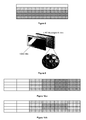
Fig. 6 is a diagram of the viewing angle adjustment by the backlight of the display -
Fig. 7 is a diagram showing the process of adjustment by adapting the viewing angle -
Fig. 8 is a fluorescent backlight display matrix -
Fig. 9 is a LED backlight technology -
Fig. 10a and 10b show the gradual levelling of the backlight, respectively, on the horizontal axis and in the plane structure -
Fig. 11-1-a and11-1-b shows the diagram of the vintage point calculation from the viewpoint of the viewer if auto adjust is not chosen or not given as default. -
Fig. 11-2 shows the diagram of the vintage point calculation from the viewpoint of the viewer if auto adjust is chosen or given as default. -
Fig. 12a,12b,12c , show three examples of backlight adaptation for LED and fluorescent displays. - LCD's produce their image by having a film that when a current runs through the pixel, it turns the shade of color. The problem associated with such LCD film technology is that this color can only be accurately represented when viewed straight on. The further away from a perpendicular viewing angle, the more the color will tend to wash out. LCD monitors are generally rated, on the market, for their visible viewing angle for both horizontal and vertical. This is rated in degrees and is the arc of a semicircle whose center is at the perpendicular to the screen. A theoretical viewing angle of 180 degrees would mean that it is fully visible from any angle in front of the screen. A higher viewing angle is preferred over a lower angle unless you happen to want some security with your screen.
- There is need for adjusting the viewing angle of the display especially for a target user at a specific location for a specific private message which is desired to be seen by him not by anybody else who is not looking from the right angle. This is also a kind of privatization up to the viewpoint of the targeted group of persons. The technical problem to be solved is to determine the position of the user and the viewing angle up to the position of the user. Once obtained the position of the viewer then the limitation of the viewing angle of the display or the shifting of the viewing angle off the display is realized by adequately adapting the backlight technology.
- The present invention uses a viewing angle adjustment methodology that exploits the transformation of bisectional geometry and it arranges the backlight matrix elements according to the viewpoint. The reorganization of the backlight matrix system gradually decreases or increases the backlight intensity of each matrix element following a pattern process defined in the flow chart of
Fig. 11-1-a-b andFig 11-2 with the objective of adjusting the viewing angle of the display. The most important steps of this process are: pointing the focus of the display up to the viewpoint of the user, rearranging the backlight matrix (especially for LED Backlight displays) in one (viewing angle in horizontal or vertical axis), two (viewing angle in horizontal) and vertical axis) or three dimensions (viewing angle in horizontal and vertical axis and distance from the screen) and adjusting the viewing angle up to calculated viewpoint. - A key step of this process is therefore the calculation of the viewpoint and in particular how a 3D system can be subdivided into a 2D system to be solved by adequately arranging the backlight illumination.
- A first step is related to the identification of the viewpoint in the horizontal axis and the other to the identification of the viewpoint on the vertical axis. In LED backlight displays both vertical and horizontal) axis are needed, though in fluorescent Backlight technology only one axis is enough. The calculation methodology for one axis may be applied also to the other axis, so for the sake of simplicity it will not be repeated for the other axis.
- With reference to
Fig. 3 , where the geometrical problem is explained, the exploitation of the geometrical properties is used to shape the size of the viewing angle for personalization. - Specifically it is known that:


from which it is derived that
and therefore
- The viewing angle of the user is then symmetrically divided into two equal angles from the perspective of the user. It is assumed to be a bisector from that location and the focus on the screen is calculated in relation with this assumption.
- With reference to
Fig. 4 and exploiting the teaching of Eq. 5, we have Eq. 6
- The distance of the user from the display can be measured with the help of RFID, IR or video and image processing related technologies, so that the values of "b" and "c" are available for the computations. The value of "a", as depicted in
Fig. 4 , is the length or width of the display and it is known "a priori". So by employing the teaching ofFig. 4 it is possible to find the focus point on the screen up to the viewpoint of the user. - With reference to
Fig. 5 , "a" indicates the length or width of the screen and "n" the number of columns, respectively rows of the LED backlight matrix. - According to the x value which defines the focus matrix element of the display (calculated up to the viewpoint of the user) the back light matrix is then rearranged by employing the following method:

- a1 is the distance of the focal point on the panel as in
Fig. 4 - x = the column number where the bisector is pointed
- round x to the nearest integer
- if x is at an equal distance from two integers then take both areas
- if

- After the rearrangement the display backlight matrix will be ready to be used for the backlight intensity adjustment to limit or increase or shift the viewing angle of the display.
Fig. 6 shows a 3D LED Backlight Display matrix rearrangement sample. - With the data representing the viewpoint information, combined with the viewing angle, the backlight is adequately changed by the driver of the display. The backlight driver adapts the specific brightness for each matrix element of the backlight (it can be one row matrix for current fluorescent technology or a matrix for LED Backlight technology or a column for side backlight technology). The value of the intensity of the backlight changes the brightness of that region of the display which is inversely proportional to the contrast ratio. Increasing the backlight intensity of the display means increasing the brightness of the display which results in decreasing contrast ratio. The viewing angle is assumed to be the angle where the contrast ratio becomes 10:1 or less. So by decreasing the back light intensity of the display it is possible to adjust the contrast ratio.
- Backlight intensity can be adjusted via several methods after the measurement of viewpoint by specifying the matrix structure of the backlight depending on the viewpoint information and on the distance from the screen. The intensity of the backlight will therefore change gradually starting from the located viewpoint on the screen. Gradually adapting algorithms may be adjusted such that the intensity of the backlight may be kept as the default value for the viewpoint on the screen and it will be gradually decreased or increased as the distance increases from the aforementioned point. This is shown in
Fig. 7 and also in the flowchart ofFig. 11-1-a-b andFig 11-2 . - The main advantage of the system over other conventional methods is the adaptability of the quality and the personalization and the technical feature throughout which this is realized. This main advantage consists in the fact that the contrast ratio of the backlight of the display is adjusted up to the location of the viewer by employing data coming from the location sensors. Such location sensors can be RFID tags connected to the user, IR sensors on the remote controller, image processing sensors or else which can define the location of the user.
- With the help of this data and the capability of dividing the screen into smaller pieces and treat it as a matrix of LEDs, it is possible to adapt the viewing angle of the display to customize it for the position and needs of the user.
- Moreover this method, by recognizing the position of the user, allows the display to follow the steps of the user such that he can see different contents depending on the user location. This is an important feature for digital signage technology applications. Since privatization is a very hot topic nowadays this technology will give control for the personalization of the content displayed on the screen.
Claims (19)
- A backlight module (101) for providing backlight to a display panel for displaying images or video with a single wide viewing angle, said backlight module (101) being divided into a plurality of regions and characterized in that it comprises- a backlight controlling device (102) which changes the luminance level of said plurality of regions to reduce said single wide viewing angle.
- The backlight module (101) of claim 1 wherein said backlight controlling device (102) changes the luminance level of said plurality of regions to create two or more viewing angles narrower than said single wide viewing angle.
- The backlight module (101) of claim 2 wherein said backlight controlling device (102) changes the luminance level of said plurality of regions to reduce said wide viewing angle on the horizontal or vertical plane.
- The backlight module (101) of claim 2 wherein said backlight controlling device (102) changes the luminance level of said plurality of regions to reduce said wide viewing angle on the horizontal and vertical plane.
- The backlight module (101) of any preceding claims wherein said backlight controlling device (102) changes the luminance level of said plurality of regions such that the viewing angle of the user is symmetrically divided into two equal angles from the perspective of the viewer.
- The backlight module (101) of any preceding claims wherein said backlight controlling device (102) comprises receiving means (103) for receiving information representing the position of a viewer.
- The backlight module (101) of any preceding claims wherein said backlight controlling device (102) continuously re-arranges the luminance level of said plurality of regions by varying the focus point of the backlight module according to the changing position of a viewer.
- A display device comprising:- a display panel- a backlight module (101) as claimed in any of the preceding claims
- The display device of claim 8 further comprising means for determining the presence and the position of one or more viewers with respect to said display.
- The display of claim 9, wherein said means for determining the presence and the position of one or more viewers with respect to said display are based on RFID or IR technologies.
- The display of claim 9, wherein said means for determining the presence and the position of one or more viewers with respect to said display comprise a camera and image processing computation means for determining the position of a viewer with respect to said display.
- The display of claims 8-11 further comprising a default operational mode that is a mode with a wide viewing angle and a narrow viewing angle operational mode automatically activated when said means for determining the position of a viewer detect the presence of a viewer.
- The display of claims 8-12 wherein the display is an LCD display.
- A method for providing backlight to a display panel for displaying images or video with a single wide viewing angle, comprising employing a backlight module (101) being divided into a plurality of regions and comprising controlling backlighting, characterized in that:- the luminance level of said plurality of regions is changed to reduce said single wide viewing angle.
- The method of claim 14 wherein said backlight controlling changes the luminance level of said plurality of regions to create two or more viewing angles narrower than said single wide viewing angle.
- The method of claim 15 wherein said backlight controlling changes the luminance level of said plurality of regions to reduce wide viewing angle on the horizontal or vertical plane.
- The method of claim 15 wherein said backlight controlling changes the luminance level of said plurality of regions to reduce wide viewing angle on the horizontal and vertical plane.
- The method of claims 14-17 wherein said backlight controlling, once provided with information representing the position of the viewer, changes the luminance level of said plurality of regions such that the viewing angle of the user is symmetrically divided into two equal angles from the perspective of the viewer.
- The method of claims 14-18 wherein said backlight controlling continuously changes the luminance level of said plurality of regions by varying the focus point of the backlight module according to the changing position of the viewer.
Applications Claiming Priority (1)
| Application Number | Priority Date | Filing Date | Title |
|---|---|---|---|
| TR2010/01102A TR201001102A2 (en) | 2010-02-12 | 2010-02-12 | Customize the LED backlit display @ |
Publications (1)
| Publication Number | Publication Date |
|---|---|
| EP2362373A1 true EP2362373A1 (en) | 2011-08-31 |
Family
ID=43877101
Family Applications (1)
| Application Number | Title | Priority Date | Filing Date |
|---|---|---|---|
| EP11152872A Ceased EP2362373A1 (en) | 2010-02-12 | 2011-02-01 | Personalization of the viewing angle in LED backlight displays |
Country Status (2)
| Country | Link |
|---|---|
| EP (1) | EP2362373A1 (en) |
| TR (1) | TR201001102A2 (en) |
Cited By (1)
| Publication number | Priority date | Publication date | Assignee | Title |
|---|---|---|---|---|
| US9905142B2 (en) | 2016-01-28 | 2018-02-27 | International Business Machines Corporation | Uni-directional and multi-directional interchangeable screen |
Citations (8)
| Publication number | Priority date | Publication date | Assignee | Title |
|---|---|---|---|---|
| EP0540137A1 (en) * | 1991-10-28 | 1993-05-05 | Nippon Hoso Kyokai | Three-dimensional image display using electrically generated parallax barrier stripes |
| US5489917A (en) | 1991-05-15 | 1996-02-06 | International Business Machines Corporation | LCD apparatus with improved gray scale at large viewing angles and method and apparatus for driving same |
| US6628255B1 (en) | 1999-06-30 | 2003-09-30 | Agilent Technologies, Inc. | Viewing angle adjustment for a liquid crystal display (LCD) |
| WO2005071656A1 (en) * | 2004-01-20 | 2005-08-04 | Koninklijke Philips Electronics, N.V. | Message board with dynamic message relocation |
| US20050184952A1 (en) * | 2004-02-09 | 2005-08-25 | Akitoyo Konno | Liquid crystal display apparatus |
| WO2007004377A1 (en) * | 2005-07-01 | 2007-01-11 | Matsushita Electric Industrial Co., Ltd. | Liquid crystal display apparatus |
| GB2457690A (en) * | 2008-02-21 | 2009-08-26 | Sharp Kk | Viewer position tracking display |
| US20100013872A1 (en) * | 2007-06-11 | 2010-01-21 | Takeshi Masuda | Liquid crystal display device |
-
2010
- 2010-02-12 TR TR2010/01102A patent/TR201001102A2/en unknown
-
2011
- 2011-02-01 EP EP11152872A patent/EP2362373A1/en not_active Ceased
Patent Citations (9)
| Publication number | Priority date | Publication date | Assignee | Title |
|---|---|---|---|---|
| US5489917A (en) | 1991-05-15 | 1996-02-06 | International Business Machines Corporation | LCD apparatus with improved gray scale at large viewing angles and method and apparatus for driving same |
| EP0540137A1 (en) * | 1991-10-28 | 1993-05-05 | Nippon Hoso Kyokai | Three-dimensional image display using electrically generated parallax barrier stripes |
| US6628255B1 (en) | 1999-06-30 | 2003-09-30 | Agilent Technologies, Inc. | Viewing angle adjustment for a liquid crystal display (LCD) |
| WO2005071656A1 (en) * | 2004-01-20 | 2005-08-04 | Koninklijke Philips Electronics, N.V. | Message board with dynamic message relocation |
| US20050184952A1 (en) * | 2004-02-09 | 2005-08-25 | Akitoyo Konno | Liquid crystal display apparatus |
| WO2007004377A1 (en) * | 2005-07-01 | 2007-01-11 | Matsushita Electric Industrial Co., Ltd. | Liquid crystal display apparatus |
| US20100208163A1 (en) * | 2005-07-01 | 2010-08-19 | Ryuji Fuchikami | Liquid crystal display apparatus |
| US20100013872A1 (en) * | 2007-06-11 | 2010-01-21 | Takeshi Masuda | Liquid crystal display device |
| GB2457690A (en) * | 2008-02-21 | 2009-08-26 | Sharp Kk | Viewer position tracking display |
Non-Patent Citations (2)
| Title |
|---|
| WIKIPEDIA, 15 August 2008 (2008-08-15), Retrieved from the Internet <URL:http://en.wikipedia.org/wiki/Viewing_cone> [retrieved on 20140113] * |
| WIKIPEDIA: "Viewing Angle", 16 September 2008 (2008-09-16), Retrieved from the Internet <URL:http://en.wikipedia.org/wiki/Viewing_angle> [retrieved on 20140113] * |
Cited By (1)
| Publication number | Priority date | Publication date | Assignee | Title |
|---|---|---|---|---|
| US9905142B2 (en) | 2016-01-28 | 2018-02-27 | International Business Machines Corporation | Uni-directional and multi-directional interchangeable screen |
Also Published As
| Publication number | Publication date |
|---|---|
| TR201001102A2 (en) | 2011-09-21 |
Similar Documents
| Publication | Publication Date | Title |
|---|---|---|
| US20140210873A1 (en) | Display system, display apparatus and control method of display apparatus | |
| US9230465B2 (en) | Stereoscopic display apparatus and adjustment method | |
| US9412336B2 (en) | Dynamic backlight control for spatially independent display regions | |
| CN101981497B (en) | High Contrast LCD Display with Adjustable White Point | |
| US9812052B2 (en) | 2D/3D image displaying apparatus | |
| US20020167461A1 (en) | Wearable display and method of displaying images using a wearable display | |
| US20140009377A1 (en) | Liquid crystal display apparatus with private mode | |
| CN104615395B (en) | A kind of method for displaying image, device and multidomain display device | |
| KR20110078292A (en) | Multi image display system | |
| US20120044272A1 (en) | Display apparatus and driving method of display panel thereof | |
| US6392657B1 (en) | Method and apparatus for characterizing an optimal viewing angle of flat display | |
| CN104570430A (en) | Display method and device applied to MVA (Multi-domain Vertical Alignment) wide-view-angle liquid crystal screen | |
| US9264700B2 (en) | Multi viewer display and displaying method of the same | |
| US20100245339A1 (en) | Method of preventing image sticking on a tft-lcd | |
| WO2008099318A1 (en) | Visual display system and method for displaying a video signal | |
| TW201103005A (en) | A display apparatus with auto brightness adjustment and method thereof | |
| CN102770797B (en) | Method and apparatus for reducing off-axis halos | |
| US20050104874A1 (en) | Display apparatus and method of eliminating afterimage thereof | |
| JP2007158787A (en) | Display device and display control method | |
| WO2016170793A1 (en) | Display device and a method of driving thereof | |
| US9325980B2 (en) | 3D display panel and 3D display apparatus using the same and driving method thereof | |
| US8803775B2 (en) | Motion image data sequence, a method for generating the sequence, and a display apparatus using the sequence | |
| US9105218B2 (en) | Display device capable of controlling external light and method for controlling external light | |
| US11900891B2 (en) | Backlight system, display apparatus, and light emission control method | |
| CN108352152B (en) | Image data processing method, pixel data generating method, and display device |
Legal Events
| Date | Code | Title | Description |
|---|---|---|---|
| PUAI | Public reference made under article 153(3) epc to a published international application that has entered the european phase |
Free format text: ORIGINAL CODE: 0009012 |
|
| AK | Designated contracting states |
Kind code of ref document: A1 Designated state(s): AL AT BE BG CH CY CZ DE DK EE ES FI FR GB GR HR HU IE IS IT LI LT LU LV MC MK MT NL NO PL PT RO RS SE SI SK SM TR |
|
| AX | Request for extension of the european patent |
Extension state: BA ME |
|
| 17P | Request for examination filed |
Effective date: 20120203 |
|
| 17Q | First examination report despatched |
Effective date: 20130902 |
|
| APBK | Appeal reference recorded |
Free format text: ORIGINAL CODE: EPIDOSNREFNE |
|
| APBN | Date of receipt of notice of appeal recorded |
Free format text: ORIGINAL CODE: EPIDOSNNOA2E |
|
| APAF | Appeal reference modified |
Free format text: ORIGINAL CODE: EPIDOSCREFNE |
|
| APBT | Appeal procedure closed |
Free format text: ORIGINAL CODE: EPIDOSNNOA9E |
|
| STAA | Information on the status of an ep patent application or granted ep patent |
Free format text: STATUS: THE APPLICATION HAS BEEN REFUSED |
|
| 18R | Application refused |
Effective date: 20160713 |