EP2361865A1 - Device and method for producing stacks from a flow of shingled printed products - Google Patents
Device and method for producing stacks from a flow of shingled printed products Download PDFInfo
- Publication number
- EP2361865A1 EP2361865A1 EP20110153779 EP11153779A EP2361865A1 EP 2361865 A1 EP2361865 A1 EP 2361865A1 EP 20110153779 EP20110153779 EP 20110153779 EP 11153779 A EP11153779 A EP 11153779A EP 2361865 A1 EP2361865 A1 EP 2361865A1
- Authority
- EP
- European Patent Office
- Prior art keywords
- stacking
- stack
- shaft
- intermediate element
- stacking shaft
- Prior art date
- Legal status (The legal status is an assumption and is not a legal conclusion. Google has not performed a legal analysis and makes no representation as to the accuracy of the status listed.)
- Granted
Links
Images


Classifications
-
- B—PERFORMING OPERATIONS; TRANSPORTING
- B65—CONVEYING; PACKING; STORING; HANDLING THIN OR FILAMENTARY MATERIAL
- B65H—HANDLING THIN OR FILAMENTARY MATERIAL, e.g. SHEETS, WEBS, CABLES
- B65H31/00—Pile receivers
- B65H31/32—Auxiliary devices for receiving articles during removal of a completed pile
-
- B—PERFORMING OPERATIONS; TRANSPORTING
- B65—CONVEYING; PACKING; STORING; HANDLING THIN OR FILAMENTARY MATERIAL
- B65H—HANDLING THIN OR FILAMENTARY MATERIAL, e.g. SHEETS, WEBS, CABLES
- B65H29/00—Delivering or advancing articles from machines; Advancing articles to or into piles
- B65H29/26—Delivering or advancing articles from machines; Advancing articles to or into piles by dropping the articles
- B65H29/34—Delivering or advancing articles from machines; Advancing articles to or into piles by dropping the articles from supports slid from under the articles
-
- B—PERFORMING OPERATIONS; TRANSPORTING
- B65—CONVEYING; PACKING; STORING; HANDLING THIN OR FILAMENTARY MATERIAL
- B65H—HANDLING THIN OR FILAMENTARY MATERIAL, e.g. SHEETS, WEBS, CABLES
- B65H31/00—Pile receivers
- B65H31/04—Pile receivers with movable end support arranged to recede as pile accumulates
- B65H31/08—Pile receivers with movable end support arranged to recede as pile accumulates the articles being piled one above another
- B65H31/10—Pile receivers with movable end support arranged to recede as pile accumulates the articles being piled one above another and applied at the top of the pile
-
- B—PERFORMING OPERATIONS; TRANSPORTING
- B65—CONVEYING; PACKING; STORING; HANDLING THIN OR FILAMENTARY MATERIAL
- B65H—HANDLING THIN OR FILAMENTARY MATERIAL, e.g. SHEETS, WEBS, CABLES
- B65H2301/00—Handling processes for sheets or webs
- B65H2301/40—Type of handling process
- B65H2301/42—Piling, depiling, handling piles
- B65H2301/426—Forming batches
- B65H2301/4262—Forming batches by inserting auxiliary support as defined in B65H31/32
- B65H2301/42622—Forming batches by inserting auxiliary support as defined in B65H31/32 and using auxiliary means for facilitating introduction of the auxiliary support
Definitions
- the invention relates to a method and an apparatus for forming stacks from a continuous stream of printed products conveyed in the direction of a stacking shaft.
- the shingled stream transported on an endless conveyor is usually slowed or even stopped to create a gap between two printed products.
- an intermediate element is introduced in the stacking shaft and formed on this one of the subsequent printed products existing sub-stack.
- solutions are also known in which the scale flow is accelerated in its downstream region or in which upstream parts of the scale flow slows down and downstream parts are accelerated.
- the shingled stream is fed continuously to the stacking shaft, the stacks formed in this way being separated later.
- the corresponding method can not be automated at a reasonable cost.
- An apparatus is also known, with which printed products delivered on a conveyor belt in a flaky arrangement are vertically stacked and output in the form of sub-stacks of a desired number.
- This device has one on the conveyor belt facing away Side of the stacking shaft arranged first support fingers. This is moved from a starting position in which it protrudes above the scale flow in the center of the stacking shaft, vertically in a protruding into the scale flow end position. The conveyed after taking the end position of the first support finger in the stacking tray printed products are thus stored forming a partial stack on this support finger.
- a second, arranged on the side facing the conveyor belt side of the stacking shaft support finger is also inserted into the stacking shaft and is used together with the first support finger of the support of the sub-stack and its separation from the previous part of the stack or the main stack.
- the printed products of the sub-stack fall on the arranged in the stacking stack support stack forming a main stack.
- a disadvantage of such a device is that at high feeding speeds of the imbricated flow thin printed products can be deformed and damaged by the support fingers or protrude during the intermediate storage on both sides of the respective support finger in the stack well below the horizontal and therefore can fall into deformed. This in turn can lead to malfunction and downtime of the entire system.
- the object of the invention is to provide a suitable for high processing speeds and the use of thin printed products simple and reliable method and a corresponding device for forming vertical stacks of a shingled stream of printed products.
- the extension of the auxiliary rake from its rest position takes place at approximately the same speed as the scale flow and at least approximately horizontally into the stacking shaft.
- This synchronized motion provides additional security for clean separation of products at a desired location, as varying speeds between auxiliary rake and scale flow at high processing speeds can result in mechanical deformation forces or electrostatic charges that can damage thin or large area printed products.
- a synchronous activation of the auxiliary rake with the shingled stream can advantageously take place in order to ensure the above-described required movement sequences within the stacking device.
- the driving of the auxiliary rake and the intermediate element takes place via a combined machine control. This has the advantage that an even more accurate control of the interacting components of the inventive device can be achieved.
- the present apparatus By forming stacks at a constant speed of the imbricated flow, the present apparatus enables a delay-free processing in stacking the printed products, whereby high processing speeds can be achieved.
- a stacking device comprises an endless conveyor and a stacking shaft arranged downstream of the endless conveyor, with an intermediate element accommodating an intermediate stack and with a stacking tray arranged in the stacking shaft for stacking a continuous flow of printed products conveyed in the direction of the stacking shaft, the stacking device having a in the stacking shaft extendable auxiliary rake, which is arranged above the intermediate element and which is extendable into the stacking shaft with an at least approximately the same speed as the scale flow.
- the auxiliary rake can also be introduced into the stacking shaft at a speed which is lower than the shingled flow, with an additional safeguard against infringement of the printed products due to the gentle advance of the shingled flow.
- the auxiliary rake is arranged so that it extends across an entire width of the stacking shaft transversely to a conveying direction of the scale flow.
- the endless conveyors have a plurality of parallel and spaced apart circulating conveyor belts.
- the stacking device in which spaces are formed between the spaced-apart conveyor belts and the auxiliary rake is arranged in a retracted rest position in the interstices. This can ensure that when the auxiliary rake is extended into its end position, the printed products rest at the same height as on the endless conveyor. This proves especially useful when large processing speeds are to be achieved and also when using thin printed products.
- the circulating elements, over which the conveyor belts are guided may be formed as rollers, gears or similar components, depending on the embodiment of the endless conveyor as a belt, belt, toothed belt or chain conveyor.
- the drive units for the intermediate element and the auxiliary rake can be either pneumatic, hydraulic, electrical or similar drive devices, wherein a corresponding drive control can be provided for the inventive motion sequence.
- the apparatus 1 has a horizontal endless conveyor 4 designed as a conveyor belt and a vertical stacking shaft 5 adjoining it in a conveying direction.
- a stack tray 6 is arranged in the stacking shaft 5.
- At the endless conveyor 4 side facing the stacking shaft 5 designed as a rake intermediate element 7 is arranged.
- the device 1 has an auxiliary rake 8, which is arranged at the level of the scale flow 2 on the endless conveyor 4 and substantially horizontally formed in the stacking shaft 5 can be introduced.
- FIGS. 2 to 8 the method steps according to the invention are illustrated with reference to an embodiment of the device 1.
- Fig. 2 shows the formation of a main stack 9 in the stacking shaft 5 on the stack tray 6, wherein both the intermediate element 7 and the auxiliary rake 8 are in a rest position.
- the stack tray 6 is continuously lowered according to the growing main stack 9.
- the formed from the printed products 3 Schuppenstrom 2 is shown on the endless conveyor 4.
- Fig. 3 shows the extension of the auxiliary rake 8 between the incoming printed products 3 of the scale flow 2 upon reaching the number of printed products 3 provided for the main stack 9.
- the auxiliary rake 8 is moved into the stacking shaft 5 at approximately the same speed as the scale flow 2 and at least approximately horizontally.
- the upstream ends of the printed products 3 are now supported on the auxiliary rake 8, while the downstream ends of these printed products 3 are further deposited on the stack tray 6 and on the printed products 3 of the main stack 9 already located thereon.
- Fig. 4 shows the auxiliary rake 8 in its extended end position. Simultaneously with the achievement of this end position of the auxiliary rake 8, the stack tray 6 and thus also the main stack 9 are lowered, wherein a free space 10 is formed for the extension of the intermediate element 7.
- the auxiliary rake 8 itself does not form a partial stack, but prevents the downstream ends of the printed products 3 from falling further into the stacking shaft 5. In the space 10 generated by the auxiliary rake 8, the intermediate element 7 can retract without damaging printed products 3.
- Fig. 5 represents the intermediate element 7 in its extended end position, in which the downstream ends of the previously deposited so far on the main stack 9 printed products 3 have been taken over by the intermediate element 7.
- the following printed products 3 are now deposited in each case with their upstream end on the auxiliary rake 8 and with its downstream end on the intermediate element 7 or on the respective printed products 3 already located thereon.
- Fig. 6 shows in its rest position entering auxiliary rake 8, whereby the upstream ends of the previously stored on the auxiliary rake printed products 3 are transferred to the intermediate element 7 to form a partial stack 11. The further formation of the sub-stack 11 then takes place on the self-lowering intermediate element 7, wherein the main stack 9 is further lowered with the stack tray 6.
- Fig. 7 indicates after the removal of the main stack 9 not shown taking off the stack tray 6 to below the intermediate element 7, the latter being retracted on reaching the upper position of the stack tray 6 in its rest position and the part stack 11 is transferred to the stack tray 6.
- the now subsequent training of the main stack 4 takes place on the stack tray 6, analog Fig. 2 ,
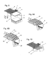
- FIG. 8 is a device 1 according to the invention with lying on the endless conveyor 4 and over the stacking shaft 5, in the conveying direction 16 moving shingled stream 2 of printed products 3 shown.
- the stacking shaft 5 with the width 15 both on the stack tray 6 resting main stack 9 as well as a resting on the intermediate element 7 part stack 11th
- Fig. 9 shows a plan view of the inventive device 1 with an enlarged illustrated auxiliary rake 8, which is arranged in approximately the same height as the endless conveyor 4, on the auxiliary rake 8 in the retracted position ( Fig. 9B ) and in the extended position ( Fig. 9A ), in which the upstream ends of the following, not shown here printed products 3 can be supported on the auxiliary rake 8.
- the in the Figs. 9A and 9B enlarged details also include a support member 18, on which the auxiliary rake 8 is fixed, and a slide bar 19, on which the support member 18 is slidably disposed.
- the endless conveyor (4) which has a plurality of parallel and through intermediate spaces (17) spaced from each other circulating conveyor belts (12), wherein the conveyor belts (12) are guided around the circulation elements (13).
- the in the Figs. 9, 9A and 9B shown recess 20 in the stacking shaft 5 is provided for the up and down movement of the intermediate element 7.
- Fig. 10 shows a plan view of the inventive device 1 also without the printed products to be stacked to illustrate the arrangement of the intermediate element 7 in its extended end position in the stacking shaft 5.
- the intermediate element 7 is shown in its retracted into the stacking shaft 5 end position.
- the drive units 14 for the intermediate element 7 and the auxiliary rake 8 can be seen.
Abstract
Description
Die Erfindung betrifft ein Verfahren und eine Vorrichtung zum Bilden von Stapeln aus einem kontinuierlich in Richtung eines Stapelschachtes geförderten Schuppenstrom von Druckprodukten.The invention relates to a method and an apparatus for forming stacks from a continuous stream of printed products conveyed in the direction of a stacking shaft.
Bei schnell-laufenden Vorrichtungen der oben genannten Art wird der auf einem Endlosförderer transportierte Schuppenstrom üblicherweise verlangsamt oder sogar angehalten, um eine Lücke zwischen zwei Druckprodukten zu erzeugen. In diese Lücke wird im Stapelschacht ein Zwischenelement eingeführt und auf diesem ein aus den nachfolgenden Druckprodukten bestehender Teilstapel gebildet. Zur Bildung einer solchen Lücke sind auch Lösungen bekannt, bei denen der Schuppenstrom in seinem stromabwärtigen Bereich beschleunigt wird oder bei denen stromaufwärtige Teile des Schuppenstroms verlangsamt und stromabwärtige Teile beschleunigt werden.In fast-running devices of the above type, the shingled stream transported on an endless conveyor is usually slowed or even stopped to create a gap between two printed products. In this gap, an intermediate element is introduced in the stacking shaft and formed on this one of the subsequent printed products existing sub-stack. To form such a gap, solutions are also known in which the scale flow is accelerated in its downstream region or in which upstream parts of the scale flow slows down and downstream parts are accelerated.
Aufgrund derartiger Geschwindigkeitsänderungen gelangt eine Unruhe in den Schuppenstrom, welche die Stapelbildung erschweren oder gar unterbrechen kann. Dabei kann es zu einer veränderten Schuppenlänge bis hin zur negativen Überschuppung sowie zu einem seitlichen Versatz, zu einer Schräglage und auch zu Beschädigungen einzelner oder mehrerer Druckprodukte im Teilstapel und damit zu Problemen beim Bilden des Hauptstapels kommen.Due to such changes in speed a disturbance enters the scale flow, which can complicate the stacking or even interrupt. This can lead to a changed scale length up to the negative overlapping and to a lateral offset, to an inclined position and also to damage of individual or several printed products in the partial stack and to get into problems while making the main pile.
Bei anderen bekannten Vorrichtungen wird der Schuppenstrom dem Stapelschacht kontinuierlich zugeführt, wobei die auf diese Weise gebildeten Stapel erst später getrennt werden. Das entsprechende Verfahren lässt sich jedoch mit vertretbarem Aufwand nicht automatisieren.In other known devices, the shingled stream is fed continuously to the stacking shaft, the stacks formed in this way being separated later. However, the corresponding method can not be automated at a reasonable cost.
Aus der
Aus der
Bei Trenneinrichtungen, die an der dem Förderband abgewandten Seite des Stapelschachtes angeordnet und insbesondere als Rechen ausgebildet sind und die mit einer hoher Geschwindigkeit betrieben werden, kann es insbesondere bei Verwendung von dünnen oder grossflächigen Druckprodukten dazu kommen, dass das erste Produkt nach der Trennstelle vom Rechen derart ergriffen wird, dass es teilweise oberhalb und teilweise unterhalb der Finger des Rechens positioniert ist und zudem beschädigt werden kann. Da ein solches verklemmtes Druckprodukt im normalen Produktionsprozess nicht automatisch entfernt werden kann, ist auch hierbei ein Herunterfahren der gesamten Anlage erforderlich.In separation devices which are arranged on the side facing away from the conveyor belt of the stacking shaft and in particular designed as a rake and operated at a high speed, it may happen, especially when using thin or large-scale printed products, that the first product after the separation point of the rake so taken is that it is partially positioned above and partially below the fingers of the rake and also can be damaged. Since such a jammed print product can not be removed automatically in the normal production process, a shutdown of the entire system is also required here.
Aufgabe der Erfindung ist es, ein auch für grosse Verarbeitungsgeschwindigkeiten und zur Verwendung von dünnen Druckprodukten geeignetes einfaches und funktionssicheres Verfahren sowie eine entsprechende Vorrichtung zum Bilden von vertikalen Stapeln aus einem Schuppenstrom von Druckprodukten bereitzustellen.The object of the invention is to provide a suitable for high processing speeds and the use of thin printed products simple and reliable method and a corresponding device for forming vertical stacks of a shingled stream of printed products.
Die Aufgabe wird nach den Merkmalen des kennzeichnenden Teils der Patentansprüche 1 und 6 gelöst. Dabei werden zum Bilden von Stapeln aus einem kontinuierlich in Richtung eines Stapelschachtes geförderten Schuppenstrom von Druckprodukten folgende Schritte ausgeführt:
- Bilden eines Hauptstapels im Stapelschacht auf einer Stapelablage, wobei sich ein Zwischenelement in einer Ruheposition ausserhalb des Stapelschachts befindet,
- Ausfahren des Zwischenelements in eine Endstellung im Stapelschacht,
- Ablegen der Druckprodukte auf dem Zwischenelement bzw. auf den jeweils auf diesen bereits befindlichen Druckprodukten, wobei sich auf dem Zwischenelement ein Teilstapel bildet
- Abtransport des Hauptstapels aus dem Stapelschacht,
- Einfahren des Zwischenelements in seine Ruheposition ausserhalb des Stapelschachts,
- Übergabe des bisherigen Teilstapels als neuer Hauptstapel an die Stapelablage, wobei
- vor dem Ausfahren des Zwischenelements ein Hilfsrechen aus einer Ruheposition ausserhalb des Stapelschachts in eine Endstellung im Stapelschacht ausgefahren wird,
- Absenken der Stapelablage,
- Ausbilden eines freien Zwischenraums zwischen Hauptstapel und Teilstapel unterhalb des Hilfsrechens,
- Ausfahren des Zwischenelements in den freien Zwischenraum und anschliessend in seine Endstellung im Stapelschacht und
- Einfahren des Hilfsrechens in seine Ruheposition.
- Forming a main stack in the stacking shaft on a stacking tray, wherein an intermediate element is in a rest position outside the stacking shaft,
- Extending the intermediate element into an end position in the stacking shaft,
- Depositing the printed products on the intermediate element or on the print products already present thereon, with a partial stack forming on the intermediate element
- Removal of the main stack from the stacking shaft,
- Retracting the intermediate element into its rest position outside the stacking shaft,
- Transfer of the previous sub-stack as a new main stack to the stack tray, where
- before extending the intermediate element, an auxiliary rake is extended from a rest position outside the stacking shaft into an end position in the stacking shaft,
- Lowering the stacker tray,
- Forming a free space between the main stack and the sub-stack underneath the auxiliary rake,
- Extending the intermediate element in the free space and then in its end position in the stacking shaft and
- Retracting the auxiliary rake in its rest position.
Ein Vorteil im Bezug auf bisher bekannte Verfahren liegt hier darin, dass der durch den Hilfsrechen gebildete freie Zwischenraum ein Ausfahren des Zwischenelements in eine "sichere Lücke" ermöglicht, ohne dass dabei unkontrolliert in den bisher gebildeten Stapel aus Druckprodukten eingestochen wird. Damit lässt sich eine Verletzung oder Verformung dieser Druckprodukte vermeiden, was zu einer Prozess-Sicherheit auch bei hohen Zuführgeschwindigkeiten führt.An advantage with respect to methods known hitherto lies in the fact that the free space formed by the auxiliary rake makes it possible to move the intermediate element out into a "safe gap" without being pierced uncontrollably into the previously formed stack of printed products. This prevents injury or deformation of these printed products, which leads to process reliability even at high feed rates.
Vorteilhaft erfolgt das Ausfahren des Hilfsrechens aus seiner Ruheposition mit annähernd gleicher Geschwindigkeit wie der Schuppenstrom und zumindest annähernd horizontal in den Stapelschacht hinein. Dieser synchronisierte Bewegungsablauf bietet eine zusätzliche Sicherheit für eine saubere Trennung der Produkte an einer gewünschten Stelle, da unterschiedliche Geschwindigkeiten zwischen Hilfsrechen und Schuppenstrom bei hohen Verarbeitungsgeschwindigkeiten zu mechanischen Verformungskräften oder elektrostatischen Aufladungen führen können, die dünne oder grossflächige Druckprodukte beschädigen können. Durch Ansteuern des Hilfsrechens über eine Maschinensteuerung, kann vorteilhaft ein synchrones Ansteuern des Hilfsrechens mit dem Schuppenstrom erfolgen, um die o.g. erforderlichen Bewegungsabläufe innerhalb der Stapelvorrichtung sicherzustellen. Darüber hinaus erfolgt in einer weiteren Ausführungsform das Ansteuern des Hilfsrechens und des Zwischenelements über eine kombinierte Maschinensteuerung. Dies birgt den Vorteil in sich, dass eine noch genauere Ansteuerung der zusammenwirkenden Komponenten der erfindungsgemässen Vorrichtung erzielt werden kann.Advantageously, the extension of the auxiliary rake from its rest position takes place at approximately the same speed as the scale flow and at least approximately horizontally into the stacking shaft. This synchronized motion provides additional security for clean separation of products at a desired location, as varying speeds between auxiliary rake and scale flow at high processing speeds can result in mechanical deformation forces or electrostatic charges that can damage thin or large area printed products. By controlling the auxiliary rake via a machine control system, a synchronous activation of the auxiliary rake with the shingled stream can advantageously take place in order to ensure the above-described required movement sequences within the stacking device. In addition, in another embodiment, the driving of the auxiliary rake and the intermediate element takes place via a combined machine control. This has the advantage that an even more accurate control of the interacting components of the inventive device can be achieved.
Dadurch, dass das Bilden von Stapeln bei konstanter Geschwindigkeit des Schuppenstroms erfolgt, ermöglicht die vorliegende Vorrichtung einen verzögerungsfreien Bearbeitungsablauf beim Stapeln der Druckprodukte, wodurch hohe Verarbeitungsgeschwindigkeiten erreicht werden können.By forming stacks at a constant speed of the imbricated flow, the present apparatus enables a delay-free processing in stacking the printed products, whereby high processing speeds can be achieved.
Eine erfindungsgemässe Stapelvorrichtung umfasst einen Endlosförderer und einen stromab des Endlosförderers angeordneten Stapelschacht, mit einem in den Stapelschacht ausfahrbaren, einen Zwischenstapel aufnehmenden Zwischenelement und mit einer im Stapelschacht angeordneten Stapelablage, zum Stapeln eines kontinuierlich in Richtung des Stapelschachts geförderten Schuppenstroms von Druckprodukten, wobei die Stapelvorrichtung einen in den Stapelschacht ausfahrbaren Hilfsrechen aufweist, der oberhalb des Zwischenelements angeordnet ist und der mit einer zumindest annähernd gleichen Geschwindigkeit wie der Schuppenstrom in den Stapelschacht hinein ausfahrbar ist. In einer weiteren Ausführungsform kann der Hilfsrechen auch mit einer kleineren Geschwindigkeit als der Schuppenstrom in den Stapelschacht eingeführt werden, wobei wegen des sanften Vorausgleitens des Schuppenstroms eine zusätzliche Absicherung gegen eine Verletzung der Druckprodukte erfolgt.A stacking device according to the invention comprises an endless conveyor and a stacking shaft arranged downstream of the endless conveyor, with an intermediate element accommodating an intermediate stack and with a stacking tray arranged in the stacking shaft for stacking a continuous flow of printed products conveyed in the direction of the stacking shaft, the stacking device having a in the stacking shaft extendable auxiliary rake, which is arranged above the intermediate element and which is extendable into the stacking shaft with an at least approximately the same speed as the scale flow. In a further embodiment, the auxiliary rake can also be introduced into the stacking shaft at a speed which is lower than the shingled flow, with an additional safeguard against infringement of the printed products due to the gentle advance of the shingled flow.
In einer weiteren Ausführungsform ist der Hilfsrechen so angeordnet ist, dass er sich über eine gesamte Breite des Stapelschachts quer zu einer Förderrichtung des Schuppenstroms erstreckt. Dadurch können grossformatige und dünne Druckprodukte während des erfindungsgemässen Verfahrens noch besser abgestützt werden.In a further embodiment, the auxiliary rake is arranged so that it extends across an entire width of the stacking shaft transversely to a conveying direction of the scale flow. As a result, large-format and thin printed products can be better supported during the process according to the invention.
In einer Ausführungsform der Stapelvorrichtung weisen die Endlosförderer mehrere parallel verlaufende und voneinander beabstandet umlaufende Transportbänder auf. Vorteilhaft erweist sich dabei eine ausfahrbare Anordnung der Hilfsrechen in annähernd gleicher Höhe wie die Transportbänder des Endlosförderers, weil damit eine versatzfreie Übernahme der Druckprodukte von dem Schuppenstrom beim Ausfahren des Hilfsrechens sichergestellt wird.In one embodiment of the stacking device, the endless conveyors have a plurality of parallel and spaced apart circulating conveyor belts. Advantageously proves to be an extendable arrangement of the auxiliary rake in approximately the same height as the conveyor belts of the endless conveyor, because thus an offset-free acquisition of the printed products is ensured by the scale flow when extending the auxiliary rake.
Vorteilhaft erweist sich ebenfalls eine Ausführungsform der Stapelvorrichtung, bei der zwischen den voneinander beabstandeten Transportbändern Zwischenräume ausgebildet sind und der Hilfsrechen in einer eingefahrenen Ruheposition in den Zwischenräumen angeordnet ist. Dadurch kann sichergestellt werden, dass beim Ausfahren des Hilfsrechens in seine Endstellung die Druckprodukte in gleicher Höhe wie auf dem Endlosförderer aufliegen. Dies erweist sich vor allem dann nützlich, wenn grosse Verarbeitungsgeschwindigkeiten erzielt werden sollen und auch bei der Verwendung von dünnen Druckprodukten. Die Umlaufelemente, über welche die Transportbänder geführt sind, können als Rollen, Zahnräder oder ähnliche Bauteile ausgebildet sein, je nach Ausführungsform des Endlosförderers als Band-, Riemen-, Zahnriemen- oder Kettenförderer. Die Antriebseinheiten für das Zwischenelement und den Hilfsrechen können entweder pneumatische, hydraulische, elektrische oder ähnliche Antriebs-Vorrichtungen sein, wobei eine entsprechende Antriebssteuerung für den erfindungsgemässen Bewegungsablauf vorgesehen werden kann.Advantageously, also proves an embodiment of the stacking device, in which spaces are formed between the spaced-apart conveyor belts and the auxiliary rake is arranged in a retracted rest position in the interstices. This can ensure that when the auxiliary rake is extended into its end position, the printed products rest at the same height as on the endless conveyor. This proves especially useful when large processing speeds are to be achieved and also when using thin printed products. The circulating elements, over which the conveyor belts are guided, may be formed as rollers, gears or similar components, depending on the embodiment of the endless conveyor as a belt, belt, toothed belt or chain conveyor. The drive units for the intermediate element and the auxiliary rake can be either pneumatic, hydraulic, electrical or similar drive devices, wherein a corresponding drive control can be provided for the inventive motion sequence.
Die Erfindung wird nachfolgend anhand eines Ausführungsbeispieles in Zusammenhang mit den beiliegenden Zeichnungen näher beschrieben und erläutert.The invention will be described in more detail below with reference to an embodiment in conjunction with the accompanying drawings and explained.
Es zeigen:
- Fig. 1
- eine schematische Seitenansicht einer erfindungsgemässen Vorrichtung;
- Fig. 2
- eine Darstellung im Bereich der Stapelvorrichtung von
Fig. 1 in einer ersten Betriebsstellung; - Fig. 3
- eine der
Fig. 2 entsprechende Darstellung in einer zweiten Betriebsstellung; - Fig. 4
- eine der
Fig. 2 entsprechende Darstellung in einer dritten Betriebsstellung; - Fig. 5
- eine der
Fig. 2 entsprechende Darstellung in einer vierten Betriebsstellung; - Fig. 6
- eine der
Fig. 2 entsprechende Darstellung in einer fünften Betriebsstellung;
- Fig. 7
- eine der
Fig. 2 entsprechende Darstellung in einer sechsten Betriebsstellung; - Fig. 8
- eine Draufsicht einer erfindungsgemässen Vorrichtung mit dargestelltem Schuppenstrom;
- Fig. 9
- eine Draufsicht einer erfindungsgemässen Vorrichtung;
- Fig. 9A
- vergrössert dargestellte Details im Bereich des ausgefahrenen Hilfsrechens;
- Fig. 9B
- vergrössert dargestellte Details im Bereich des eingefahrenen Hilfsrechens;
- Fig. 10
- eine Draufsicht einer erfindungsgemässen Vorrichtung ohne Druckprodukte.
- Fig. 1
- a schematic side view of an inventive device;
- Fig. 2
- a representation in the region of the stacking device of
Fig. 1 in a first operating position; - Fig. 3
- one of the
Fig. 2 corresponding representation in a second operating position; - Fig. 4
- one of the
Fig. 2 corresponding representation in a third operating position; - Fig. 5
- one of the
Fig. 2 corresponding representation in a fourth operating position; - Fig. 6
- one of the
Fig. 2 corresponding representation in a fifth operating position;
- Fig. 7
- one of the
Fig. 2 corresponding representation in a sixth operating position; - Fig. 8
- a plan view of an inventive device with illustrated scale flow;
- Fig. 9
- a plan view of an inventive device;
- Fig. 9A
- enlarged details in the area of the extended auxiliary rake;
- Fig. 9B
- enlarged details in the area of the retracted auxiliary invoice;
- Fig. 10
- a plan view of an inventive device without printed products.
In der
Zudem weist die Vorrichtung 1 einen Hilfsrechen 8 auf, der in Höhe des Schuppenstromes 2 am Endlosförderer 4 angeordnet und im Wesentlichen horizontal in den Stapelschacht 5 einbringbar ausgebildet ist.In addition, the
In den
In der Draufsicht aus
Claims (11)
dadurch gekennzeichnet, dass
characterized in that
dadurch gekennzeichnet, dass
das Ausfahren des Hilfsrechens (8) aus seiner Ruheposition in seine Endstellung mit annähernd gleicher Geschwindigkeit wie der Schuppenstrom (2) und zumindest annähernd horizontal in den Stapelschacht (5) hinein erfolgt.Method according to claim 1,
characterized in that
the extension of the auxiliary rake (8) from its rest position into its end position takes place at approximately the same speed as the imbricated stream (2) and at least approximately horizontally into the stacking shaft (5).
dadurch gekennzeichnet, dass
das Bilden von Stapeln bei konstanter Geschwindigkeit des Schuppenstroms (2) erfolgt.Method according to one of claims 1 or 2,
characterized in that
the formation of stacks at constant speed of the scale flow (2) takes place.
dadurch gekennzeichnet, dass
das Ansteuern des Hilfsrechens (8) über eine Maschinensteuerung erfolgt.Method according to one of the preceding claims,
characterized in that
the driving of the auxiliary rake (8) via a machine control takes place.
dadurch gekennzeichnet, dass
das Ansteuern des Hilfsrechens (8) und des Zwischenelements (7) über eine kombinierte Maschinensteuerung erfolgt.Method according to one of the preceding claims,
characterized in that
the driving of the auxiliary rake (8) and the intermediate element (7) takes place via a combined machine control.
dadurch gekennzeichnet, dass
die Stapelvorrichtung (1) einen in den Stapelschacht (5) ausfahrbaren Hilfsrechen (8) aufweist, der oberhalb des Zwischenelements (7) angeordnet ist und der mit einer zumindest annähernd gleichen Geschwindigkeit wie der Schuppenstrom (2) in den Stapelschacht (5) hinein ausfahrbar ist.Stacking device (1) with an endless conveyor (4) and a stacking shaft (5) arranged downstream of the endless conveyor (4), with an intermediate element (7) which can be extended into the stacking shaft (5), and an intermediate stack (5) arranged in the stacking shaft (5) Stacking tray (6), for stacking a continuous stream (2) of printed products (3) conveyed in the direction of the stacking tray (5),
characterized in that
the stacking device (1) has an auxiliary rake (8) which can be extended into the stacking shaft (5), which is arranged above the intermediate element (7) and which can be extended into the stacking shaft (5) with an at least approximately the same speed as the imbricated stream (2) is.
dadurch gekennzeichnet, dass
der Hilfsrechen (8) mit einer kleineren Geschwindigkeit als der Schuppenstrom (2) in den Stapelschacht (5) hinein bewegbar ist.Stacking device (1) according to claim 6,
characterized in that
the auxiliary rake (8) is movable into the stacking shaft (5) at a lower speed than the scale flow (2).
dadurch gekennzeichnet, dass
der Hilfsrechen (8) so angeordnet ist, dass er sich über eine gesamte Breite (15) des Stapelschachts (5) quer zu einer Förderrichtung (16) des Schuppenstroms erstreckt.Stacking device (1) according to one of the preceding claims,
characterized in that
the auxiliary rake (8) is arranged so that it extends across an entire width (15) of the stacking shaft (5) transversely to a conveying direction (16) of the scale flow.
dadurch gekennzeichnet, dass
der Endlosförderer (4) mehrere parallel verlaufende und voneinander beabstandete umlaufende Transportbänder (12) aufweist.Stacking device (1) according to claim 6 or 7
characterized in that
the endless conveyor (4) has a plurality of parallel and spaced-apart circulating conveyor belts (12).
dadurch gekennzeichnet, dass
der Hilfsrechen (8) in annähernd gleicher Höhe wie die Transportbänder (12) des Endlosförderers (4) angeordnet ist.Stacking device (1) according to one of the preceding claims,
characterized in that
the auxiliary rake (8) is arranged at approximately the same height as the conveyor belts (12) of the endless conveyor (4).
dadurch gekennzeichnet, dass
zwischen den voneinander beabstandeten Transportbändern (12) Zwischenräume (17) ausgebildet sind und der Hilfsrechen (8) in einer eingefahrenen Ruheposition in den Zwischenräumen (17) angeordnet ist.Stacking device (1) according to claim 9 or 10,
characterized in that
Between the spaced apart conveyor belts (12) intermediate spaces (17) are formed and the auxiliary rake (8) is arranged in a retracted rest position in the intermediate spaces (17).
Applications Claiming Priority (1)
| Application Number | Priority Date | Filing Date | Title |
|---|---|---|---|
| CH2102010 | 2010-02-19 |
Publications (2)
| Publication Number | Publication Date |
|---|---|
| EP2361865A1 true EP2361865A1 (en) | 2011-08-31 |
| EP2361865B1 EP2361865B1 (en) | 2015-09-16 |
Family
ID=42224603
Family Applications (1)
| Application Number | Title | Priority Date | Filing Date |
|---|---|---|---|
| EP11153779.1A Not-in-force EP2361865B1 (en) | 2010-02-19 | 2011-02-09 | Device and method for producing stacks from a flow of shingled printed products |
Country Status (5)
| Country | Link |
|---|---|
| US (1) | US9156646B2 (en) |
| EP (1) | EP2361865B1 (en) |
| JP (1) | JP2011168402A (en) |
| CN (1) | CN102161447A (en) |
| BR (1) | BRPI1100217A2 (en) |
Families Citing this family (5)
| Publication number | Priority date | Publication date | Assignee | Title |
|---|---|---|---|---|
| JP5439611B1 (en) * | 2013-01-24 | 2014-03-12 | トタニ技研工業株式会社 | Sheet product conveyor |
| CN105217357A (en) * | 2013-07-26 | 2016-01-06 | 北京印刷学院 | The delivery device of Paper-pasting machine |
| JP6468685B2 (en) * | 2015-03-31 | 2019-02-13 | リョービMhiグラフィックテクノロジー株式会社 | Sheet-fed printing machine |
| JP6995335B2 (en) * | 2017-06-16 | 2022-02-21 | 株式会社Isowa | Counter ejector |
| CN112537684A (en) * | 2020-12-28 | 2021-03-23 | 滁州卷烟材料厂 | Corrugated paper conveying and stacking device |
Citations (6)
| Publication number | Priority date | Publication date | Assignee | Title |
|---|---|---|---|---|
| DE2725267B1 (en) * | 1977-06-03 | 1978-11-09 | Bielomatik Leuze & Co | Stacking device for storing sheets |
| GB2079259A (en) * | 1980-06-23 | 1982-01-20 | Beloit Corp | Apparatus and method for the continuous collection and discharge of sheets |
| EP0718231A2 (en) * | 1994-12-22 | 1996-06-26 | Jagenberg Papiertechnik GmbH | Device for stacking sheets, in particular for paper- or paperboard sheets which are fed in overlapping streams |
| DE19855510A1 (en) | 1998-12-02 | 2000-06-08 | Ingo Ederer | Device for vertical formation of part stacks of printed items has collecting chute with auxiliary support surface with several vertically and horizontally movable fingers preferably on both sides in upper section of collecting chute |
| DE19928367A1 (en) * | 1999-06-21 | 2000-12-28 | Will E C H Gmbh & Co | Handling of stacked sheet materials has a facility for stacking and separating into selected stack size |
| DE19947329A1 (en) | 1999-10-01 | 2001-04-12 | Gramatec Grafische Maschinen T | Device for forming stacks containing desired numbers of printed products comprise stacker with floor which can be opened to remove stacked material and support finger which supports articles forming start of new stack |
Family Cites Families (18)
| Publication number | Priority date | Publication date | Assignee | Title |
|---|---|---|---|---|
| US2084741A (en) * | 1933-09-15 | 1937-06-22 | Hammermill Paper Co | Continuous automatic layboy |
| CH599025A5 (en) * | 1976-04-23 | 1978-05-12 | Grapha Holding Ag | |
| US4290723A (en) * | 1977-06-01 | 1981-09-22 | Renholmens Mekaniska Verkstad Ab | Timber package arranger |
| US4189270A (en) * | 1978-04-24 | 1980-02-19 | Georgia-Pacific Corporation | Sheet transfer and stacking apparatus |
| US4339119A (en) * | 1979-03-13 | 1982-07-13 | Tokyo Shibaura Denki Kabushiki Kaisha | Paper sheets separating apparatus |
| DE3535113A1 (en) * | 1985-10-02 | 1987-04-23 | Jagenberg Ag | BOW DEPOSIT |
| DE4131015C2 (en) * | 1991-09-18 | 1995-10-05 | Roland Man Druckmasch | Sheet boom |
| JPH0597317A (en) * | 1991-10-04 | 1993-04-20 | Dainippon Ink & Chem Inc | Temporarily holding method and device for falling sheet-like body |
| JPH05147807A (en) | 1992-01-31 | 1993-06-15 | S K Eng Kk | Sheet stacking device |
| DE19507370C2 (en) * | 1995-03-03 | 2003-01-09 | Heidelberger Druckmasch Ag | Sheet delivery for a printing machine |
| EP0737640B1 (en) * | 1995-04-15 | 2001-07-04 | Heidelberger Druckmaschinen Aktiengesellschaft | Method of and device for introducing an auxiliary pile receiver |
| ATE200770T1 (en) * | 1996-02-14 | 2001-05-15 | Roland Man Druckmasch | METHOD AND DEVICE FOR AUTOMATIC STACK CHANGE |
| US6042108A (en) * | 1997-11-26 | 2000-03-28 | Morgan; Robert A. | Zero feed interrupt sheet stacker |
| US6574943B2 (en) * | 2001-08-17 | 2003-06-10 | Blue Print Holding B.V. | Conveyor assembly for packagings, and method for delivery of a pack |
| DE10146919C1 (en) * | 2001-09-24 | 2003-05-15 | Koenig & Bauer Ag | Device for aligning sheets arranged one above the other in a layer |
| DE102004062735B4 (en) * | 2004-02-19 | 2023-08-17 | Heidelberger Druckmaschinen Ag | Device for aligning sheets that are placed on a stack of sheets |
| JP4150928B2 (en) | 2004-07-08 | 2008-09-17 | 宇央 足立 | Sheet processing method and processing apparatus, and sheet processing apparatus equipped with the apparatus |
| DE102006028381A1 (en) * | 2006-06-19 | 2007-12-20 | E.C.H. Will Gmbh | Flat parts e.g. paper sheets, stack forming method, involves withdrawing auxiliary stack carrier from stack areas to deliver partial stack formed on auxiliary stack carrier, and moving upper side of section of main stack |
-
2011
- 2011-02-09 EP EP11153779.1A patent/EP2361865B1/en not_active Not-in-force
- 2011-02-15 US US13/027,852 patent/US9156646B2/en not_active Expired - Fee Related
- 2011-02-18 JP JP2011032851A patent/JP2011168402A/en active Pending
- 2011-02-18 BR BRPI1100217 patent/BRPI1100217A2/en not_active IP Right Cessation
- 2011-02-21 CN CN2011100478096A patent/CN102161447A/en active Pending
Patent Citations (6)
| Publication number | Priority date | Publication date | Assignee | Title |
|---|---|---|---|---|
| DE2725267B1 (en) * | 1977-06-03 | 1978-11-09 | Bielomatik Leuze & Co | Stacking device for storing sheets |
| GB2079259A (en) * | 1980-06-23 | 1982-01-20 | Beloit Corp | Apparatus and method for the continuous collection and discharge of sheets |
| EP0718231A2 (en) * | 1994-12-22 | 1996-06-26 | Jagenberg Papiertechnik GmbH | Device for stacking sheets, in particular for paper- or paperboard sheets which are fed in overlapping streams |
| DE19855510A1 (en) | 1998-12-02 | 2000-06-08 | Ingo Ederer | Device for vertical formation of part stacks of printed items has collecting chute with auxiliary support surface with several vertically and horizontally movable fingers preferably on both sides in upper section of collecting chute |
| DE19928367A1 (en) * | 1999-06-21 | 2000-12-28 | Will E C H Gmbh & Co | Handling of stacked sheet materials has a facility for stacking and separating into selected stack size |
| DE19947329A1 (en) | 1999-10-01 | 2001-04-12 | Gramatec Grafische Maschinen T | Device for forming stacks containing desired numbers of printed products comprise stacker with floor which can be opened to remove stacked material and support finger which supports articles forming start of new stack |
Also Published As
| Publication number | Publication date |
|---|---|
| US9156646B2 (en) | 2015-10-13 |
| CN102161447A (en) | 2011-08-24 |
| US20110206490A1 (en) | 2011-08-25 |
| JP2011168402A (en) | 2011-09-01 |
| BRPI1100217A2 (en) | 2012-09-25 |
| EP2361865B1 (en) | 2015-09-16 |
Similar Documents
| Publication | Publication Date | Title |
|---|---|---|
| EP0187344A1 (en) | Method and device for the production of single stacks consisting of a fan folded web | |
| EP2361865B1 (en) | Device and method for producing stacks from a flow of shingled printed products | |
| EP0722415B1 (en) | Process and device for forming and moving stacks of printed sheets | |
| WO2014005715A1 (en) | Device and method for separating value documents, and value document processing system | |
| EP2955135B1 (en) | System for discharging of piles of merchandise comprising pallets with goods stacked on them, and method for discharging piles of merchandise comprising pallets with goods stacked on them | |
| EP2810904A1 (en) | Feeding of loose stacks of sheets into a transport channel | |
| DE10214684A1 (en) | Conveying device and method for transferring stacks of paper or the like onto a removal conveyor | |
| EP2581331B1 (en) | Device and method for aligning products | |
| DE1280651B (en) | Stacking device for paper or plastic film processing machines, in particular sack making machines | |
| DE102013100232A1 (en) | Method for forming gap between individual article and/or group of articles within continuous article stream, involves moving downstream conveyor section of horizontal conveyor equal to or in opposite of conveying direction of conveyor | |
| EP0514783B1 (en) | Device for the transport of stacks of paper sheets | |
| EP1350750B1 (en) | Method and device for forming piles of continuously delivered, flat ojects | |
| EP0644119A1 (en) | Method and device for the forming of stacks of individual articles, especially biscuits | |
| DE2638783C3 (en) | Sheet feeder | |
| EP2923975B1 (en) | Depalletising device and depalletising method for removing layers of packets from a stack of goods | |
| DE3423479C2 (en) | ||
| DE102017004232A1 (en) | Object transport device | |
| EP3025994B1 (en) | Device and method for manufacturing stacks of packages of individual signatures | |
| DE102008046125A1 (en) | Sheet processing machine and method for depositing sheets | |
| DE3114102A1 (en) | Process and device for feeding sheets of paper, cardboard or the like | |
| DE4415047A1 (en) | Paper sheet stack feeding process from collection point | |
| EP1784351B1 (en) | Conveying device and method for transferring sheet layers to a transport conveyor | |
| EP0216023B1 (en) | Device for regulating a stream of flat articles | |
| EP2316767B1 (en) | Device and method for manufacturing printed product stacks | |
| DE3937048C2 (en) | Device for separating a partial stack from a layer stack |
Legal Events
| Date | Code | Title | Description |
|---|---|---|---|
| PUAI | Public reference made under article 153(3) epc to a published international application that has entered the european phase |
Free format text: ORIGINAL CODE: 0009012 |
|
| AK | Designated contracting states |
Kind code of ref document: A1 Designated state(s): AL AT BE BG CH CY CZ DE DK EE ES FI FR GB GR HR HU IE IS IT LI LT LU LV MC MK MT NL NO PL PT RO RS SE SI SK SM TR |
|
| AX | Request for extension of the european patent |
Extension state: BA ME |
|
| 17P | Request for examination filed |
Effective date: 20120220 |
|
| 17Q | First examination report despatched |
Effective date: 20121005 |
|
| GRAP | Despatch of communication of intention to grant a patent |
Free format text: ORIGINAL CODE: EPIDOSNIGR1 |
|
| INTG | Intention to grant announced |
Effective date: 20150428 |
|
| RIN1 | Information on inventor provided before grant (corrected) |
Inventor name: MAIER, PETER |
|
| GRAS | Grant fee paid |
Free format text: ORIGINAL CODE: EPIDOSNIGR3 |
|
| GRAA | (expected) grant |
Free format text: ORIGINAL CODE: 0009210 |
|
| AK | Designated contracting states |
Kind code of ref document: B1 Designated state(s): AL AT BE BG CH CY CZ DE DK EE ES FI FR GB GR HR HU IE IS IT LI LT LU LV MC MK MT NL NO PL PT RO RS SE SI SK SM TR |
|
| REG | Reference to a national code |
Ref country code: GB Ref legal event code: FG4D Free format text: NOT ENGLISH |
|
| REG | Reference to a national code |
Ref country code: CH Ref legal event code: EP |
|
| REG | Reference to a national code |
Ref country code: IE Ref legal event code: FG4D Free format text: LANGUAGE OF EP DOCUMENT: GERMAN |
|
| REG | Reference to a national code |
Ref country code: AT Ref legal event code: REF Ref document number: 749630 Country of ref document: AT Kind code of ref document: T Effective date: 20151015 |
|
| REG | Reference to a national code |
Ref country code: DE Ref legal event code: R096 Ref document number: 502011007869 Country of ref document: DE |
|
| REG | Reference to a national code |
Ref country code: NL Ref legal event code: MP Effective date: 20150916 |
|
| PG25 | Lapsed in a contracting state [announced via postgrant information from national office to epo] |
Ref country code: LV Free format text: LAPSE BECAUSE OF FAILURE TO SUBMIT A TRANSLATION OF THE DESCRIPTION OR TO PAY THE FEE WITHIN THE PRESCRIBED TIME-LIMIT Effective date: 20150916 Ref country code: GR Free format text: LAPSE BECAUSE OF FAILURE TO SUBMIT A TRANSLATION OF THE DESCRIPTION OR TO PAY THE FEE WITHIN THE PRESCRIBED TIME-LIMIT Effective date: 20151217 Ref country code: NO Free format text: LAPSE BECAUSE OF FAILURE TO SUBMIT A TRANSLATION OF THE DESCRIPTION OR TO PAY THE FEE WITHIN THE PRESCRIBED TIME-LIMIT Effective date: 20151216 Ref country code: LT Free format text: LAPSE BECAUSE OF FAILURE TO SUBMIT A TRANSLATION OF THE DESCRIPTION OR TO PAY THE FEE WITHIN THE PRESCRIBED TIME-LIMIT Effective date: 20150916 Ref country code: FI Free format text: LAPSE BECAUSE OF FAILURE TO SUBMIT A TRANSLATION OF THE DESCRIPTION OR TO PAY THE FEE WITHIN THE PRESCRIBED TIME-LIMIT Effective date: 20150916 |
|
| REG | Reference to a national code |
Ref country code: LT Ref legal event code: MG4D |
|
| PG25 | Lapsed in a contracting state [announced via postgrant information from national office to epo] |
Ref country code: RS Free format text: LAPSE BECAUSE OF FAILURE TO SUBMIT A TRANSLATION OF THE DESCRIPTION OR TO PAY THE FEE WITHIN THE PRESCRIBED TIME-LIMIT Effective date: 20150916 Ref country code: SE Free format text: LAPSE BECAUSE OF FAILURE TO SUBMIT A TRANSLATION OF THE DESCRIPTION OR TO PAY THE FEE WITHIN THE PRESCRIBED TIME-LIMIT Effective date: 20150916 Ref country code: HR Free format text: LAPSE BECAUSE OF FAILURE TO SUBMIT A TRANSLATION OF THE DESCRIPTION OR TO PAY THE FEE WITHIN THE PRESCRIBED TIME-LIMIT Effective date: 20150916 |
|
| PG25 | Lapsed in a contracting state [announced via postgrant information from national office to epo] |
Ref country code: NL Free format text: LAPSE BECAUSE OF FAILURE TO SUBMIT A TRANSLATION OF THE DESCRIPTION OR TO PAY THE FEE WITHIN THE PRESCRIBED TIME-LIMIT Effective date: 20150916 |
|
| PG25 | Lapsed in a contracting state [announced via postgrant information from national office to epo] |
Ref country code: ES Free format text: LAPSE BECAUSE OF FAILURE TO SUBMIT A TRANSLATION OF THE DESCRIPTION OR TO PAY THE FEE WITHIN THE PRESCRIBED TIME-LIMIT Effective date: 20150916 Ref country code: SK Free format text: LAPSE BECAUSE OF FAILURE TO SUBMIT A TRANSLATION OF THE DESCRIPTION OR TO PAY THE FEE WITHIN THE PRESCRIBED TIME-LIMIT Effective date: 20150916 Ref country code: CZ Free format text: LAPSE BECAUSE OF FAILURE TO SUBMIT A TRANSLATION OF THE DESCRIPTION OR TO PAY THE FEE WITHIN THE PRESCRIBED TIME-LIMIT Effective date: 20150916 Ref country code: IS Free format text: LAPSE BECAUSE OF FAILURE TO SUBMIT A TRANSLATION OF THE DESCRIPTION OR TO PAY THE FEE WITHIN THE PRESCRIBED TIME-LIMIT Effective date: 20160116 Ref country code: IT Free format text: LAPSE BECAUSE OF FAILURE TO SUBMIT A TRANSLATION OF THE DESCRIPTION OR TO PAY THE FEE WITHIN THE PRESCRIBED TIME-LIMIT Effective date: 20150916 Ref country code: EE Free format text: LAPSE BECAUSE OF FAILURE TO SUBMIT A TRANSLATION OF THE DESCRIPTION OR TO PAY THE FEE WITHIN THE PRESCRIBED TIME-LIMIT Effective date: 20150916 |
|
| PG25 | Lapsed in a contracting state [announced via postgrant information from national office to epo] |
Ref country code: RO Free format text: LAPSE BECAUSE OF FAILURE TO SUBMIT A TRANSLATION OF THE DESCRIPTION OR TO PAY THE FEE WITHIN THE PRESCRIBED TIME-LIMIT Effective date: 20150916 Ref country code: PT Free format text: LAPSE BECAUSE OF FAILURE TO SUBMIT A TRANSLATION OF THE DESCRIPTION OR TO PAY THE FEE WITHIN THE PRESCRIBED TIME-LIMIT Effective date: 20160118 Ref country code: BE Free format text: LAPSE BECAUSE OF NON-PAYMENT OF DUE FEES Effective date: 20160229 Ref country code: PL Free format text: LAPSE BECAUSE OF FAILURE TO SUBMIT A TRANSLATION OF THE DESCRIPTION OR TO PAY THE FEE WITHIN THE PRESCRIBED TIME-LIMIT Effective date: 20150916 |
|
| REG | Reference to a national code |
Ref country code: DE Ref legal event code: R097 Ref document number: 502011007869 Country of ref document: DE |
|
| PLBE | No opposition filed within time limit |
Free format text: ORIGINAL CODE: 0009261 |
|
| STAA | Information on the status of an ep patent application or granted ep patent |
Free format text: STATUS: NO OPPOSITION FILED WITHIN TIME LIMIT |
|
| 26N | No opposition filed |
Effective date: 20160617 |
|
| PG25 | Lapsed in a contracting state [announced via postgrant information from national office to epo] |
Ref country code: DK Free format text: LAPSE BECAUSE OF FAILURE TO SUBMIT A TRANSLATION OF THE DESCRIPTION OR TO PAY THE FEE WITHIN THE PRESCRIBED TIME-LIMIT Effective date: 20150916 |
|
| REG | Reference to a national code |
Ref country code: DE Ref legal event code: R119 Ref document number: 502011007869 Country of ref document: DE |
|
| PG25 | Lapsed in a contracting state [announced via postgrant information from national office to epo] |
Ref country code: LU Free format text: LAPSE BECAUSE OF FAILURE TO SUBMIT A TRANSLATION OF THE DESCRIPTION OR TO PAY THE FEE WITHIN THE PRESCRIBED TIME-LIMIT Effective date: 20160209 Ref country code: MC Free format text: LAPSE BECAUSE OF FAILURE TO SUBMIT A TRANSLATION OF THE DESCRIPTION OR TO PAY THE FEE WITHIN THE PRESCRIBED TIME-LIMIT Effective date: 20150916 |
|
| REG | Reference to a national code |
Ref country code: CH Ref legal event code: PL |
|
| GBPC | Gb: european patent ceased through non-payment of renewal fee |
Effective date: 20160209 |
|
| PG25 | Lapsed in a contracting state [announced via postgrant information from national office to epo] |
Ref country code: LI Free format text: LAPSE BECAUSE OF NON-PAYMENT OF DUE FEES Effective date: 20160229 Ref country code: CH Free format text: LAPSE BECAUSE OF NON-PAYMENT OF DUE FEES Effective date: 20160229 |
|
| REG | Reference to a national code |
Ref country code: FR Ref legal event code: ST Effective date: 20161028 |
|
| PG25 | Lapsed in a contracting state [announced via postgrant information from national office to epo] |
Ref country code: SI Free format text: LAPSE BECAUSE OF FAILURE TO SUBMIT A TRANSLATION OF THE DESCRIPTION OR TO PAY THE FEE WITHIN THE PRESCRIBED TIME-LIMIT Effective date: 20150916 |
|
| REG | Reference to a national code |
Ref country code: IE Ref legal event code: MM4A |
|
| PG25 | Lapsed in a contracting state [announced via postgrant information from national office to epo] |
Ref country code: DE Free format text: LAPSE BECAUSE OF NON-PAYMENT OF DUE FEES Effective date: 20160901 Ref country code: GB Free format text: LAPSE BECAUSE OF NON-PAYMENT OF DUE FEES Effective date: 20160209 Ref country code: IE Free format text: LAPSE BECAUSE OF NON-PAYMENT OF DUE FEES Effective date: 20160209 Ref country code: FR Free format text: LAPSE BECAUSE OF NON-PAYMENT OF DUE FEES Effective date: 20160229 |
|
| REG | Reference to a national code |
Ref country code: AT Ref legal event code: MM01 Ref document number: 749630 Country of ref document: AT Kind code of ref document: T Effective date: 20160209 |
|
| PG25 | Lapsed in a contracting state [announced via postgrant information from national office to epo] |
Ref country code: AT Free format text: LAPSE BECAUSE OF NON-PAYMENT OF DUE FEES Effective date: 20160209 |
|
| PG25 | Lapsed in a contracting state [announced via postgrant information from national office to epo] |
Ref country code: MT Free format text: LAPSE BECAUSE OF FAILURE TO SUBMIT A TRANSLATION OF THE DESCRIPTION OR TO PAY THE FEE WITHIN THE PRESCRIBED TIME-LIMIT Effective date: 20150916 |
|
| PG25 | Lapsed in a contracting state [announced via postgrant information from national office to epo] |
Ref country code: HU Free format text: LAPSE BECAUSE OF FAILURE TO SUBMIT A TRANSLATION OF THE DESCRIPTION OR TO PAY THE FEE WITHIN THE PRESCRIBED TIME-LIMIT; INVALID AB INITIO Effective date: 20110209 Ref country code: SM Free format text: LAPSE BECAUSE OF FAILURE TO SUBMIT A TRANSLATION OF THE DESCRIPTION OR TO PAY THE FEE WITHIN THE PRESCRIBED TIME-LIMIT Effective date: 20150916 Ref country code: CY Free format text: LAPSE BECAUSE OF FAILURE TO SUBMIT A TRANSLATION OF THE DESCRIPTION OR TO PAY THE FEE WITHIN THE PRESCRIBED TIME-LIMIT Effective date: 20150916 |
|
| PG25 | Lapsed in a contracting state [announced via postgrant information from national office to epo] |
Ref country code: TR Free format text: LAPSE BECAUSE OF FAILURE TO SUBMIT A TRANSLATION OF THE DESCRIPTION OR TO PAY THE FEE WITHIN THE PRESCRIBED TIME-LIMIT Effective date: 20150916 Ref country code: MK Free format text: LAPSE BECAUSE OF FAILURE TO SUBMIT A TRANSLATION OF THE DESCRIPTION OR TO PAY THE FEE WITHIN THE PRESCRIBED TIME-LIMIT Effective date: 20150916 |
|
| PG25 | Lapsed in a contracting state [announced via postgrant information from national office to epo] |
Ref country code: BG Free format text: LAPSE BECAUSE OF FAILURE TO SUBMIT A TRANSLATION OF THE DESCRIPTION OR TO PAY THE FEE WITHIN THE PRESCRIBED TIME-LIMIT Effective date: 20150916 |
|
| PG25 | Lapsed in a contracting state [announced via postgrant information from national office to epo] |
Ref country code: AL Free format text: LAPSE BECAUSE OF FAILURE TO SUBMIT A TRANSLATION OF THE DESCRIPTION OR TO PAY THE FEE WITHIN THE PRESCRIBED TIME-LIMIT Effective date: 20150916 |