EP2361493A2 - Reel mower cutting unit - Google Patents
Reel mower cutting unit Download PDFInfo
- Publication number
- EP2361493A2 EP2361493A2 EP11154051A EP11154051A EP2361493A2 EP 2361493 A2 EP2361493 A2 EP 2361493A2 EP 11154051 A EP11154051 A EP 11154051A EP 11154051 A EP11154051 A EP 11154051A EP 2361493 A2 EP2361493 A2 EP 2361493A2
- Authority
- EP
- European Patent Office
- Prior art keywords
- reel
- cutting unit
- cutting
- unit
- reel mower
- Prior art date
- Legal status (The legal status is an assumption and is not a legal conclusion. Google has not performed a legal analysis and makes no representation as to the accuracy of the status listed.)
- Granted
Links
Images

Classifications
-
- A—HUMAN NECESSITIES
- A01—AGRICULTURE; FORESTRY; ANIMAL HUSBANDRY; HUNTING; TRAPPING; FISHING
- A01D—HARVESTING; MOWING
- A01D34/00—Mowers; Mowing apparatus of harvesters
- A01D34/01—Mowers; Mowing apparatus of harvesters characterised by features relating to the type of cutting apparatus
- A01D34/412—Mowers; Mowing apparatus of harvesters characterised by features relating to the type of cutting apparatus having rotating cutters
- A01D34/42—Mowers; Mowing apparatus of harvesters characterised by features relating to the type of cutting apparatus having rotating cutters having cutters rotating about a horizontal axis, e.g. cutting-cylinders
- A01D34/43—Mowers; Mowing apparatus of harvesters characterised by features relating to the type of cutting apparatus having rotating cutters having cutters rotating about a horizontal axis, e.g. cutting-cylinders mounted on a vehicle, e.g. a tractor, or drawn by an animal or a vehicle
- A01D34/44—Mowers; Mowing apparatus of harvesters characterised by features relating to the type of cutting apparatus having rotating cutters having cutters rotating about a horizontal axis, e.g. cutting-cylinders mounted on a vehicle, e.g. a tractor, or drawn by an animal or a vehicle with two or more cutters
Definitions
- This invention relates generally to reel mower cutting units, and particularly to a reel mower cutting unit with gauge wheels to prevent marks or damage to the turf when the unit is lowered onto a sloped surface.
- Grass mowing machines such as greens mowers, fairway mowers and trim mowers are commonly equipped with several reel mower cutting units to provide a high quality of cut for golf courses.
- Each reel mower cutting unit may have a generally horizontally-aligned cutting reel, and front and back rollers or caster wheels that roll in contact with the ground for supporting the unit during operation. Blades of the rotating reel interact with a bedknife to cut grass with a scissoring action.
- Each reel mower cutting unit may be attached to the outer end of a lift arm extending laterally outwardly from a traction vehicle.
- These machines may include implement lift systems to raise and lower the cutting units on the outer ends of the lift arms.
- Implement lift systems for mower cutting units may include hydraulic cylinders connected to the lift arms, or electric motors driving linear actuators.
- a hydraulic cylinder attached to a lift arm may be extended to raise a cutting unit to a transport or service position, and retracted to lower the cutting unit to a mowing position.
- Examples of grass mowing machines with hydraulic implement lift systems for mower cutting units are provided in US Patent Nos. 5,297,378 and 5,343,680 .
- Examples of grass mowing machines having electric implement lift systems for mower cutting units are shown in US Patent Nos. 5,540,037 and 5,553,445 .
- the first part of the unit to touch the ground may leave a mark on the turf. Additionally, the left or right side of a reel mower cutting unit may damage the turf as the unit slides sideways after one side reaches the ground surface. It is desirable to prevent marks caused by lowering reel mower cutting units onto sloped surfaces of a golf course, and to prevent damage to the turf as the unit slides sideways after one side reaches the ground surface.
- a reel mower cutting unit includes a horizontally aligned cutting reel rotating in proximity to a bedknife, a front roller forwardly of the cutting reel and a rear roller behind the cutting reel to support the cutting reel on the ground surface, and a pair of gauge wheels mounted to the reel mower cutting unit forwardly of the front roller.
- Each of the pair of gauge wheels have an axis that is non-parallel to the cutting reel. The gauge wheels prevent marks when the reel mower cutting unit is lowered onto sloped surfaces, and prevent damage to the turf.
- a reel mower cutting unit may comprise a horizontally aligned cutting reel rotating in proximity to a bedknife; a front roller forwardly of the cutting reel and a rear roller behind the cutting reel to support the cutting reel on the ground surface; whereas a pair of gauge wheels may be mounted to the reel mower cutting unit forwardly of the front roller and extending laterally outwardly from the reel mower cutting unit.
- Each of the pair of gauge wheels may have an axis that is fixed non-parallel to the cutting reel.
- the pair of gauge wheels may be raised off the ground while the reel mower cutting unit is supported by the front roller and rear roller on the ground surface.
- the pair of gauge wheels may have rounded edges.
- a reel mower cutting unit may comprise a cutting reel having a horizontal axis and supported by a front roller and a rear roller in a mowing position; a lift arm to raise and lower the cutting reel between a mowing position and a transport position; and a pair of gauge wheels mounted forwardly of the front roller and extending laterally outwardly from a first end and a second end of the reel mower cutting unit at a front left corner and a right front corner of the unit.
- Each gauge wheel may have rounded edges.
- Each gauge wheel may be mounted on an axis that is not parallel to the cutting reel.
- the reel mower cutting unit may further comprise a knuckle joint at the end of the lift arm to allow the unit to pivot on an axis parallel to the direction of travel.
- a reel mower cutting unit may comprise a cutting reel having a pair of gauge wheels mounted in front of the cutting reel; each gauge wheel extending laterally outwardly from a front corner of the unit on a fixed axis that is to the cutting reel.
- the reel mower cutting unit of claim may further comprise a front roller in front of the cutting reel, and a rear roller behind the cutting reel.
- the front roller and rear roller may contact the ground surface while the reel mower cutting unit is in a mowing position so that the gauge wheels are off the ground surface.
- Each gauge wheel may have rounded edges.
- the reel mower cutting unit may further comprise a lift arm pivotably mounted to a frame supporting the cutting reel.
- reel mower cutting unit 100 may have a generally cylindrical cutting reel 112 mounted in a frame and rotatable on a laterally extending horizontal axis.
- the cutting reel includes spiral blades which pass in close proximity to bed knife 114, cutting grass with a shearing action.
- Each cutting unit may have a cutting width of about 18 inches to about 36 inches.
- Grass catcher 106 may be removably attached to the front of the reel mower cutting unit.
- reel mower cutting unit 100 may be in a row of two or three reel-type cutting units carried by a traction vehicle.
- the reel mower cutting unit may be on a fairway mower, greens mower, trim mower or other grass mowing machine having one or more reel mower cutting units that may be raised and lowered to the ground surface.
- the reel mower cutting unit may be supported by front roller 102 and rear roller 104.
- one or more casters may support the reel mower cutting unit, instead of front and/or rear rollers.
- the front and rear rollers or casters may be supported by brackets mounted to the reel mower cutting unit frame, and the brackets may be adjustable vertically for raising and lowering the cutting unit frame with respect to the rollers to adjust the height at which grass is cut.
- reel mower cutting unit 100 may be carried by lift arm 108 extending from a traction vehicle.
- the lift arm may raise and lower the reel mower cutting unit between a mowing position and a transport position.
- a first or inner end of the lift arm may be pivotably attached to the frame or body of the traction vehicle, and the second or outer end of the lift arm may be pivotably attached to the reel mower cutting unit at knuckle joint 122 pivotably connected to cross bar or yoke 110 supporting the unit.
- the knuckle joint allows the reel mower cutting unit to pivot or tilt on a horizontal axis in the direction of travel.
- the reel mower cutting unit should be balanced with respect to the lift arm and knuckle joint so that the unit may be horizontally aligned while it is carried by or suspended from the lift arm above the ground surface.
- a pair of gauge wheels 116 may be mounted to reel mower cutting unit 100 at a position in front of front roller 102, at the front left corner and front right corner of the unit.
- the gauge wheels may be mounted using mounting brackets 118 that are fastened to the frame at the left and right ends of the unit.
- Each gauge wheel may be mounted at an angle directed away from the side of the cutting unit in the direction of travel, so that each gauge wheel axis 120 is not parallel to the axis of the cutting reel or front roller.
- the mounting brackets may be positioned so that the gauge wheels clear the ground, and are preferably at least about 1 cm above the ground surface, once the front and rear rollers 102, 104 contact the ground in the mowing position.
- Each gauge wheel 116 may have rounded edges so that the gauge wheel may act as a fulcrum around which reel mower cutting unit 100 may pivot from a horizontal position toward a position parallel to the ground surface.
- reel mower cutting unit 100 may be lowered to sloped ground surface 124, and gauge wheel 116 may contact the surface before any other part of the unit. Because the gauge wheel initially contacts the ground surface, the unit does not leave any mark on the turf. After the gauge wheel contacts the surface, the gauge wheel then may roll up the slope until front roller 102 touches the ground surface and lifts the gauge wheel off the ground, as shown in Fig. 3 . The gauge wheel also may prevent the reel mower cutting unit from sliding sideways after the gauge wheel makes contact, and may prevent any part of the unit from damaging the turf.
Landscapes
- Life Sciences & Earth Sciences (AREA)
- Environmental Sciences (AREA)
- Harvester Elements (AREA)
Abstract
Description
- This invention relates generally to reel mower cutting units, and particularly to a reel mower cutting unit with gauge wheels to prevent marks or damage to the turf when the unit is lowered onto a sloped surface.
- Grass mowing machines such as greens mowers, fairway mowers and trim mowers are commonly equipped with several reel mower cutting units to provide a high quality of cut for golf courses. Each reel mower cutting unit may have a generally horizontally-aligned cutting reel, and front and back rollers or caster wheels that roll in contact with the ground for supporting the unit during operation. Blades of the rotating reel interact with a bedknife to cut grass with a scissoring action. Each reel mower cutting unit may be attached to the outer end of a lift arm extending laterally outwardly from a traction vehicle.
- These machines may include implement lift systems to raise and lower the cutting units on the outer ends of the lift arms. Implement lift systems for mower cutting units may include hydraulic cylinders connected to the lift arms, or electric motors driving linear actuators. For example, a hydraulic cylinder attached to a lift arm may be extended to raise a cutting unit to a transport or service position, and retracted to lower the cutting unit to a mowing position. Examples of grass mowing machines with hydraulic implement lift systems for mower cutting units are provided in
US Patent Nos. 5,297,378 and5,343,680 . Examples of grass mowing machines having electric implement lift systems for mower cutting units are shown inUS Patent Nos. 5,540,037 and5,553,445 . - As the implement lift system lowers a reel mower cutting unit onto a sloped surface of a golf course, the first part of the unit to touch the ground may leave a mark on the turf. Additionally, the left or right side of a reel mower cutting unit may damage the turf as the unit slides sideways after one side reaches the ground surface. It is desirable to prevent marks caused by lowering reel mower cutting units onto sloped surfaces of a golf course, and to prevent damage to the turf as the unit slides sideways after one side reaches the ground surface.
- It is therefore the object of the present invention to overcome some or all of these disadvantages.
- This object is met according to the invention by the teaching of claim 1 while features developing the solution in an advantageous manner are set forth in the further claims.
- A reel mower cutting unit includes a horizontally aligned cutting reel rotating in proximity to a bedknife, a front roller forwardly of the cutting reel and a rear roller behind the cutting reel to support the cutting reel on the ground surface, and a pair of gauge wheels mounted to the reel mower cutting unit forwardly of the front roller. Each of the pair of gauge wheels have an axis that is non-parallel to the cutting reel. The gauge wheels prevent marks when the reel mower cutting unit is lowered onto sloped surfaces, and prevent damage to the turf.
- A reel mower cutting unit may comprise a horizontally aligned cutting reel rotating in proximity to a bedknife; a front roller forwardly of the cutting reel and a rear roller behind the cutting reel to support the cutting reel on the ground surface; whereas a pair of gauge wheels may be mounted to the reel mower cutting unit forwardly of the front roller and extending laterally outwardly from the reel mower cutting unit.
- Each of the pair of gauge wheels may have an axis that is fixed non-parallel to the cutting reel.
- The pair of gauge wheels may be raised off the ground while the reel mower cutting unit is supported by the front roller and rear roller on the ground surface.
- The pair of gauge wheels may have rounded edges.
- A reel mower cutting unit, may comprise a cutting reel having a horizontal axis and supported by a front roller and a rear roller in a mowing position; a lift arm to raise and lower the cutting reel between a mowing position and a transport position; and
a pair of gauge wheels mounted forwardly of the front roller and extending laterally outwardly from a first end and a second end of the reel mower cutting unit at a front left corner and a right front corner of the unit. - Each gauge wheel may have rounded edges.
- Each gauge wheel may be mounted on an axis that is not parallel to the cutting reel.
- The reel mower cutting unit may further comprise a knuckle joint at the end of the lift arm to allow the unit to pivot on an axis parallel to the direction of travel.
- A reel mower cutting unit may comprise a cutting reel having a pair of gauge wheels mounted in front of the cutting reel; each gauge wheel extending laterally outwardly from a front corner of the unit on a fixed axis that is to the cutting reel.
- The reel mower cutting unit of claim may further comprise a front roller in front of the cutting reel, and a rear roller behind the cutting reel.
- The front roller and rear roller may contact the ground surface while the reel mower cutting unit is in a mowing position so that the gauge wheels are off the ground surface.
- Each gauge wheel may have rounded edges.
- The reel mower cutting unit may further comprise a lift arm pivotably mounted to a frame supporting the cutting reel.
- Embodiments of the invention described below are shown in the drawings, in which:
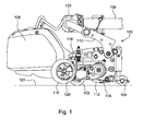
- Fig. 1
- is a side view of a reel mower cutting unit with gauge wheels according to a first embodiment of the invention.
- Fig. 2
- is a front view of a reel mower cutting unit with gauge wheels contacting a sloped ground surface before other parts of the unit reach the surface, according to a first embodiment of the invention.
- Fig. 3
- is a front view of a reel mower cutting unit with gauge wheels after the cutting unit reaches the ground surface according to a first embodiment of the invention.
- In a preferred embodiment shown in
Figs. 1-3 , reelmower cutting unit 100 may have a generallycylindrical cutting reel 112 mounted in a frame and rotatable on a laterally extending horizontal axis. The cutting reel includes spiral blades which pass in close proximity tobed knife 114, cutting grass with a shearing action. Each cutting unit may have a cutting width of about 18 inches to about 36 inches.Grass catcher 106 may be removably attached to the front of the reel mower cutting unit. - In one embodiment, reel
mower cutting unit 100 may be in a row of two or three reel-type cutting units carried by a traction vehicle. For example, the reel mower cutting unit may be on a fairway mower, greens mower, trim mower or other grass mowing machine having one or more reel mower cutting units that may be raised and lowered to the ground surface. - In the mowing position, the reel mower cutting unit may be supported by
front roller 102 andrear roller 104. Alternatively, one or more casters may support the reel mower cutting unit, instead of front and/or rear rollers. The front and rear rollers or casters may be supported by brackets mounted to the reel mower cutting unit frame, and the brackets may be adjustable vertically for raising and lowering the cutting unit frame with respect to the rollers to adjust the height at which grass is cut. - In one embodiment, reel
mower cutting unit 100 may be carried bylift arm 108 extending from a traction vehicle. The lift arm may raise and lower the reel mower cutting unit between a mowing position and a transport position. A first or inner end of the lift arm may be pivotably attached to the frame or body of the traction vehicle, and the second or outer end of the lift arm may be pivotably attached to the reel mower cutting unit atknuckle joint 122 pivotably connected to cross bar oryoke 110 supporting the unit. The knuckle joint allows the reel mower cutting unit to pivot or tilt on a horizontal axis in the direction of travel. The reel mower cutting unit should be balanced with respect to the lift arm and knuckle joint so that the unit may be horizontally aligned while it is carried by or suspended from the lift arm above the ground surface. - In one embodiment, a pair of
gauge wheels 116 may be mounted to reelmower cutting unit 100 at a position in front offront roller 102, at the front left corner and front right corner of the unit. The gauge wheels may be mounted usingmounting brackets 118 that are fastened to the frame at the left and right ends of the unit. Each gauge wheel may be mounted at an angle directed away from the side of the cutting unit in the direction of travel, so that eachgauge wheel axis 120 is not parallel to the axis of the cutting reel or front roller. Additionally, the mounting brackets may be positioned so that the gauge wheels clear the ground, and are preferably at least about 1 cm above the ground surface, once the front andrear rollers gauge wheel 116 may have rounded edges so that the gauge wheel may act as a fulcrum around which reelmower cutting unit 100 may pivot from a horizontal position toward a position parallel to the ground surface. - As shown in
Fig. 2 , reelmower cutting unit 100 may be lowered to slopedground surface 124, andgauge wheel 116 may contact the surface before any other part of the unit. Because the gauge wheel initially contacts the ground surface, the unit does not leave any mark on the turf. After the gauge wheel contacts the surface, the gauge wheel then may roll up the slope untilfront roller 102 touches the ground surface and lifts the gauge wheel off the ground, as shown inFig. 3 . The gauge wheel also may prevent the reel mower cutting unit from sliding sideways after the gauge wheel makes contact, and may prevent any part of the unit from damaging the turf. - Having described a preferred embodiment, it will become apparent that various modifications can be made without departing from the scope of the invention as defined in the accompanying claims.
Claims (4)
- A reel mower cutting unit (100), comprising a horizontally aligned cutting reel (112) rotating in proximity to a bedknife (114); a front roller (102) forwardly of the cutting reel (112) and a rear roller (104) behind the cutting reel (112) to support the cutting reel (112) on the ground surface; characterized by a pair of gauge wheels (116) mounted to the reel mower cutting unit (100) forwardly of the front roller (102) and extending laterally outwardly from the reel mower cutting unit (100).
- The reel mower cutting unit according to claim 1, characterized in that each of the pair of gauge wheels (116) have an axis that is fixed non-parallel to the cutting reel (112).
- The reel mower cutting unit according to claim 1 or 2, characterized in that the pair of gauge wheels (116) are raised off the ground while the reel mower cutting unit (100) is supported by the front roller (102) and rear roller (104) on the ground surface.
- The reel mower cutting unit according to one of the previous claims, characterized in that the pair of gauge wheels (116) have rounded edges.
Applications Claiming Priority (1)
| Application Number | Priority Date | Filing Date | Title |
|---|---|---|---|
| US12/707,013 US8136334B2 (en) | 2010-02-17 | 2010-02-17 | Reel mower cutting unit with gauge wheels |
Publications (3)
| Publication Number | Publication Date |
|---|---|
| EP2361493A2 true EP2361493A2 (en) | 2011-08-31 |
| EP2361493A3 EP2361493A3 (en) | 2011-11-23 |
| EP2361493B1 EP2361493B1 (en) | 2013-03-06 |
Family
ID=44276328
Family Applications (1)
| Application Number | Title | Priority Date | Filing Date |
|---|---|---|---|
| EP11154051A Active EP2361493B1 (en) | 2010-02-17 | 2011-02-10 | Reel mower cutting unit |
Country Status (2)
| Country | Link |
|---|---|
| US (1) | US8136334B2 (en) |
| EP (1) | EP2361493B1 (en) |
Families Citing this family (4)
| Publication number | Priority date | Publication date | Assignee | Title |
|---|---|---|---|---|
| US9027318B2 (en) * | 2012-02-07 | 2015-05-12 | IHI Shibaura Machinery Corporation | Reel lawn mower with main body, reel cutting unit, and connection structure for connecting reel cutting unit to main body such that reel cutting unit is rollable |
| US9861035B2 (en) * | 2015-05-01 | 2018-01-09 | Deere & Company | Height of cut control system |
| US20160316619A1 (en) * | 2015-05-01 | 2016-11-03 | Deere & Company | Height of cut control system |
| CN108934423A (en) * | 2018-07-05 | 2018-12-07 | 中南林业科技大学 | Twin shaft crushing type weeding operation head and crushing type weeding operational method |
Citations (3)
| Publication number | Priority date | Publication date | Assignee | Title |
|---|---|---|---|---|
| US5297378A (en) | 1992-05-13 | 1994-03-29 | Deere & Company | Suspension mechanism for reel mowers |
| US5343680A (en) | 1992-09-03 | 1994-09-06 | Deere & Company | Suspension mechanism for reel mowers |
| US5540037A (en) | 1994-02-03 | 1996-07-30 | Ransomes America Corporation | Control system for electric drive riding mower |
Family Cites Families (8)
| Publication number | Priority date | Publication date | Assignee | Title |
|---|---|---|---|---|
| US1767510A (en) * | 1926-07-12 | 1930-06-24 | Jacobsen Mfg Co | Power-driven lawn mower |
| US2972218A (en) * | 1958-05-23 | 1961-02-21 | Toro Mfg Corp | Power mower with full floating cutting unit |
| US2968906A (en) | 1958-09-08 | 1961-01-24 | Toro Mfg Corp | Lawn mower roller and support |
| US3668847A (en) | 1971-02-26 | 1972-06-13 | Carl Van Ausdall | Rotary cutting reel, ledger blade and baffle assembly |
| US3824772A (en) | 1972-01-25 | 1974-07-23 | Hahn Inc | Turf maintenance machine |
| US4162605A (en) * | 1978-02-07 | 1979-07-31 | The Toro Company | Rear wheel support apparatus for a three wheel vehicle |
| US5228277A (en) * | 1992-01-23 | 1993-07-20 | Deere & Company | Rear discharge reel mower having multi-purpose rotary brush |
| US5533326A (en) * | 1995-02-24 | 1996-07-09 | The Toro Company | Reel mower |
-
2010
- 2010-02-17 US US12/707,013 patent/US8136334B2/en active Active
-
2011
- 2011-02-10 EP EP11154051A patent/EP2361493B1/en active Active
Patent Citations (4)
| Publication number | Priority date | Publication date | Assignee | Title |
|---|---|---|---|---|
| US5297378A (en) | 1992-05-13 | 1994-03-29 | Deere & Company | Suspension mechanism for reel mowers |
| US5343680A (en) | 1992-09-03 | 1994-09-06 | Deere & Company | Suspension mechanism for reel mowers |
| US5540037A (en) | 1994-02-03 | 1996-07-30 | Ransomes America Corporation | Control system for electric drive riding mower |
| US5553445A (en) | 1994-02-03 | 1996-09-10 | Ransomes America Corporation | Riding mower with swingout center mower head |
Also Published As
| Publication number | Publication date |
|---|---|
| EP2361493B1 (en) | 2013-03-06 |
| US20110197562A1 (en) | 2011-08-18 |
| US8136334B2 (en) | 2012-03-20 |
| EP2361493A3 (en) | 2011-11-23 |
Similar Documents
| Publication | Publication Date | Title |
|---|---|---|
| EP3086632B1 (en) | Agricultural machine | |
| JP3623244B2 (en) | Reel lawn mower suspension device | |
| EP2050329B1 (en) | Grass Mowing Machine | |
| EP2361493B1 (en) | Reel mower cutting unit | |
| US4622806A (en) | Ditch swather | |
| EP2687074A1 (en) | Support carriage for an agricultural machine | |
| EP3440916B1 (en) | Triplex greensmower lift system | |
| EP1685758B1 (en) | Coupling mechanism and mowing machine | |
| US5687555A (en) | Apparatus for mowing, aerating, and/or collecting | |
| CN109379988B (en) | Open foot platform of triple mower | |
| EP1900274B1 (en) | Mechanism for offsetting cutting units for a grass mowing machine and grass mowing machine | |
| EP1305993A1 (en) | Roadside mower | |
| EP2702857B1 (en) | Reel mower grass catcher carrier | |
| EP1800532B1 (en) | Mowing machine | |
| KR20160090718A (en) | Lawn trimmer of large area of traction type | |
| EP3646695B1 (en) | Triplex greensmower open foot platform cover | |
| JP4092567B2 (en) | Mid-mount foliage harvester | |
| JP3558547B2 (en) | Lawn mower | |
| US20140215994A1 (en) | Reel mower grass catcher carrier |
Legal Events
| Date | Code | Title | Description |
|---|---|---|---|
| PUAI | Public reference made under article 153(3) epc to a published international application that has entered the european phase |
Free format text: ORIGINAL CODE: 0009012 |
|
| AK | Designated contracting states |
Kind code of ref document: A2 Designated state(s): AL AT BE BG CH CY CZ DE DK EE ES FI FR GB GR HR HU IE IS IT LI LT LU LV MC MK MT NL NO PL PT RO RS SE SI SK SM TR |
|
| AX | Request for extension of the european patent |
Extension state: BA ME |
|
| PUAL | Search report despatched |
Free format text: ORIGINAL CODE: 0009013 |
|
| AK | Designated contracting states |
Kind code of ref document: A3 Designated state(s): AL AT BE BG CH CY CZ DE DK EE ES FI FR GB GR HR HU IE IS IT LI LT LU LV MC MK MT NL NO PL PT RO RS SE SI SK SM TR |
|
| AX | Request for extension of the european patent |
Extension state: BA ME |
|
| RIC1 | Information provided on ipc code assigned before grant |
Ipc: A01D 34/44 20060101AFI20111020BHEP |
|
| 17P | Request for examination filed |
Effective date: 20120523 |
|
| GRAP | Despatch of communication of intention to grant a patent |
Free format text: ORIGINAL CODE: EPIDOSNIGR1 |
|
| GRAS | Grant fee paid |
Free format text: ORIGINAL CODE: EPIDOSNIGR3 |
|
| GRAA | (expected) grant |
Free format text: ORIGINAL CODE: 0009210 |
|
| AK | Designated contracting states |
Kind code of ref document: B1 Designated state(s): AL AT BE BG CH CY CZ DE DK EE ES FI FR GB GR HR HU IE IS IT LI LT LU LV MC MK MT NL NO PL PT RO RS SE SI SK SM TR |
|
| REG | Reference to a national code |
Ref country code: GB Ref legal event code: FG4D |
|
| REG | Reference to a national code |
Ref country code: CH Ref legal event code: EP Ref country code: AT Ref legal event code: REF Ref document number: 599075 Country of ref document: AT Kind code of ref document: T Effective date: 20130315 |
|
| REG | Reference to a national code |
Ref country code: IE Ref legal event code: FG4D |
|
| REG | Reference to a national code |
Ref country code: DE Ref legal event code: R096 Ref document number: 602011000948 Country of ref document: DE Effective date: 20130502 |
|
| REG | Reference to a national code |
Ref country code: AT Ref legal event code: MK05 Ref document number: 599075 Country of ref document: AT Kind code of ref document: T Effective date: 20130306 |
|
| PG25 | Lapsed in a contracting state [announced via postgrant information from national office to epo] |
Ref country code: AT Free format text: LAPSE BECAUSE OF FAILURE TO SUBMIT A TRANSLATION OF THE DESCRIPTION OR TO PAY THE FEE WITHIN THE PRESCRIBED TIME-LIMIT Effective date: 20130306 Ref country code: ES Free format text: LAPSE BECAUSE OF FAILURE TO SUBMIT A TRANSLATION OF THE DESCRIPTION OR TO PAY THE FEE WITHIN THE PRESCRIBED TIME-LIMIT Effective date: 20130617 Ref country code: SE Free format text: LAPSE BECAUSE OF FAILURE TO SUBMIT A TRANSLATION OF THE DESCRIPTION OR TO PAY THE FEE WITHIN THE PRESCRIBED TIME-LIMIT Effective date: 20130306 Ref country code: NO Free format text: LAPSE BECAUSE OF FAILURE TO SUBMIT A TRANSLATION OF THE DESCRIPTION OR TO PAY THE FEE WITHIN THE PRESCRIBED TIME-LIMIT Effective date: 20130606 Ref country code: BG Free format text: LAPSE BECAUSE OF FAILURE TO SUBMIT A TRANSLATION OF THE DESCRIPTION OR TO PAY THE FEE WITHIN THE PRESCRIBED TIME-LIMIT Effective date: 20130606 Ref country code: LT Free format text: LAPSE BECAUSE OF FAILURE TO SUBMIT A TRANSLATION OF THE DESCRIPTION OR TO PAY THE FEE WITHIN THE PRESCRIBED TIME-LIMIT Effective date: 20130306 |
|
| REG | Reference to a national code |
Ref country code: NL Ref legal event code: VDEP Effective date: 20130306 |
|
| REG | Reference to a national code |
Ref country code: LT Ref legal event code: MG4D |
|
| PG25 | Lapsed in a contracting state [announced via postgrant information from national office to epo] |
Ref country code: GR Free format text: LAPSE BECAUSE OF FAILURE TO SUBMIT A TRANSLATION OF THE DESCRIPTION OR TO PAY THE FEE WITHIN THE PRESCRIBED TIME-LIMIT Effective date: 20130607 Ref country code: SI Free format text: LAPSE BECAUSE OF FAILURE TO SUBMIT A TRANSLATION OF THE DESCRIPTION OR TO PAY THE FEE WITHIN THE PRESCRIBED TIME-LIMIT Effective date: 20130306 Ref country code: FI Free format text: LAPSE BECAUSE OF FAILURE TO SUBMIT A TRANSLATION OF THE DESCRIPTION OR TO PAY THE FEE WITHIN THE PRESCRIBED TIME-LIMIT Effective date: 20130306 Ref country code: LV Free format text: LAPSE BECAUSE OF FAILURE TO SUBMIT A TRANSLATION OF THE DESCRIPTION OR TO PAY THE FEE WITHIN THE PRESCRIBED TIME-LIMIT Effective date: 20130306 |
|
| PG25 | Lapsed in a contracting state [announced via postgrant information from national office to epo] |
Ref country code: HR Free format text: LAPSE BECAUSE OF FAILURE TO SUBMIT A TRANSLATION OF THE DESCRIPTION OR TO PAY THE FEE WITHIN THE PRESCRIBED TIME-LIMIT Effective date: 20130306 Ref country code: BE Free format text: LAPSE BECAUSE OF FAILURE TO SUBMIT A TRANSLATION OF THE DESCRIPTION OR TO PAY THE FEE WITHIN THE PRESCRIBED TIME-LIMIT Effective date: 20130306 Ref country code: RS Free format text: LAPSE BECAUSE OF FAILURE TO SUBMIT A TRANSLATION OF THE DESCRIPTION OR TO PAY THE FEE WITHIN THE PRESCRIBED TIME-LIMIT Effective date: 20130306 |
|
| PG25 | Lapsed in a contracting state [announced via postgrant information from national office to epo] |
Ref country code: SK Free format text: LAPSE BECAUSE OF FAILURE TO SUBMIT A TRANSLATION OF THE DESCRIPTION OR TO PAY THE FEE WITHIN THE PRESCRIBED TIME-LIMIT Effective date: 20130306 Ref country code: NL Free format text: LAPSE BECAUSE OF FAILURE TO SUBMIT A TRANSLATION OF THE DESCRIPTION OR TO PAY THE FEE WITHIN THE PRESCRIBED TIME-LIMIT Effective date: 20130306 Ref country code: CZ Free format text: LAPSE BECAUSE OF FAILURE TO SUBMIT A TRANSLATION OF THE DESCRIPTION OR TO PAY THE FEE WITHIN THE PRESCRIBED TIME-LIMIT Effective date: 20130306 Ref country code: EE Free format text: LAPSE BECAUSE OF FAILURE TO SUBMIT A TRANSLATION OF THE DESCRIPTION OR TO PAY THE FEE WITHIN THE PRESCRIBED TIME-LIMIT Effective date: 20130306 Ref country code: RO Free format text: LAPSE BECAUSE OF FAILURE TO SUBMIT A TRANSLATION OF THE DESCRIPTION OR TO PAY THE FEE WITHIN THE PRESCRIBED TIME-LIMIT Effective date: 20130306 Ref country code: IS Free format text: LAPSE BECAUSE OF FAILURE TO SUBMIT A TRANSLATION OF THE DESCRIPTION OR TO PAY THE FEE WITHIN THE PRESCRIBED TIME-LIMIT Effective date: 20130706 Ref country code: PT Free format text: LAPSE BECAUSE OF FAILURE TO SUBMIT A TRANSLATION OF THE DESCRIPTION OR TO PAY THE FEE WITHIN THE PRESCRIBED TIME-LIMIT Effective date: 20130708 |
|
| PG25 | Lapsed in a contracting state [announced via postgrant information from national office to epo] |
Ref country code: PL Free format text: LAPSE BECAUSE OF FAILURE TO SUBMIT A TRANSLATION OF THE DESCRIPTION OR TO PAY THE FEE WITHIN THE PRESCRIBED TIME-LIMIT Effective date: 20130306 |
|
| PLBE | No opposition filed within time limit |
Free format text: ORIGINAL CODE: 0009261 |
|
| STAA | Information on the status of an ep patent application or granted ep patent |
Free format text: STATUS: NO OPPOSITION FILED WITHIN TIME LIMIT |
|
| PG25 | Lapsed in a contracting state [announced via postgrant information from national office to epo] |
Ref country code: DK Free format text: LAPSE BECAUSE OF FAILURE TO SUBMIT A TRANSLATION OF THE DESCRIPTION OR TO PAY THE FEE WITHIN THE PRESCRIBED TIME-LIMIT Effective date: 20130306 |
|
| 26N | No opposition filed |
Effective date: 20131209 |
|
| PG25 | Lapsed in a contracting state [announced via postgrant information from national office to epo] |
Ref country code: IT Free format text: LAPSE BECAUSE OF FAILURE TO SUBMIT A TRANSLATION OF THE DESCRIPTION OR TO PAY THE FEE WITHIN THE PRESCRIBED TIME-LIMIT Effective date: 20130306 |
|
| REG | Reference to a national code |
Ref country code: DE Ref legal event code: R097 Ref document number: 602011000948 Country of ref document: DE Effective date: 20131209 |
|
| PG25 | Lapsed in a contracting state [announced via postgrant information from national office to epo] |
Ref country code: LU Free format text: LAPSE BECAUSE OF FAILURE TO SUBMIT A TRANSLATION OF THE DESCRIPTION OR TO PAY THE FEE WITHIN THE PRESCRIBED TIME-LIMIT Effective date: 20140210 Ref country code: MC Free format text: LAPSE BECAUSE OF FAILURE TO SUBMIT A TRANSLATION OF THE DESCRIPTION OR TO PAY THE FEE WITHIN THE PRESCRIBED TIME-LIMIT Effective date: 20130306 |
|
| REG | Reference to a national code |
Ref country code: CH Ref legal event code: PL |
|
| PG25 | Lapsed in a contracting state [announced via postgrant information from national office to epo] |
Ref country code: LI Free format text: LAPSE BECAUSE OF NON-PAYMENT OF DUE FEES Effective date: 20140228 Ref country code: CH Free format text: LAPSE BECAUSE OF NON-PAYMENT OF DUE FEES Effective date: 20140228 |
|
| REG | Reference to a national code |
Ref country code: FR Ref legal event code: ST Effective date: 20141031 |
|
| REG | Reference to a national code |
Ref country code: IE Ref legal event code: MM4A |
|
| PG25 | Lapsed in a contracting state [announced via postgrant information from national office to epo] |
Ref country code: IE Free format text: LAPSE BECAUSE OF NON-PAYMENT OF DUE FEES Effective date: 20140210 Ref country code: FR Free format text: LAPSE BECAUSE OF NON-PAYMENT OF DUE FEES Effective date: 20140228 |
|
| PG25 | Lapsed in a contracting state [announced via postgrant information from national office to epo] |
Ref country code: MT Free format text: LAPSE BECAUSE OF FAILURE TO SUBMIT A TRANSLATION OF THE DESCRIPTION OR TO PAY THE FEE WITHIN THE PRESCRIBED TIME-LIMIT Effective date: 20130306 |
|
| PG25 | Lapsed in a contracting state [announced via postgrant information from national office to epo] |
Ref country code: SM Free format text: LAPSE BECAUSE OF FAILURE TO SUBMIT A TRANSLATION OF THE DESCRIPTION OR TO PAY THE FEE WITHIN THE PRESCRIBED TIME-LIMIT Effective date: 20130306 |
|
| PG25 | Lapsed in a contracting state [announced via postgrant information from national office to epo] |
Ref country code: CY Free format text: LAPSE BECAUSE OF FAILURE TO SUBMIT A TRANSLATION OF THE DESCRIPTION OR TO PAY THE FEE WITHIN THE PRESCRIBED TIME-LIMIT Effective date: 20130306 |
|
| PG25 | Lapsed in a contracting state [announced via postgrant information from national office to epo] |
Ref country code: TR Free format text: LAPSE BECAUSE OF FAILURE TO SUBMIT A TRANSLATION OF THE DESCRIPTION OR TO PAY THE FEE WITHIN THE PRESCRIBED TIME-LIMIT Effective date: 20130306 Ref country code: HU Free format text: LAPSE BECAUSE OF FAILURE TO SUBMIT A TRANSLATION OF THE DESCRIPTION OR TO PAY THE FEE WITHIN THE PRESCRIBED TIME-LIMIT; INVALID AB INITIO Effective date: 20110210 |
|
| PG25 | Lapsed in a contracting state [announced via postgrant information from national office to epo] |
Ref country code: MK Free format text: LAPSE BECAUSE OF FAILURE TO SUBMIT A TRANSLATION OF THE DESCRIPTION OR TO PAY THE FEE WITHIN THE PRESCRIBED TIME-LIMIT Effective date: 20130306 |
|
| PG25 | Lapsed in a contracting state [announced via postgrant information from national office to epo] |
Ref country code: AL Free format text: LAPSE BECAUSE OF FAILURE TO SUBMIT A TRANSLATION OF THE DESCRIPTION OR TO PAY THE FEE WITHIN THE PRESCRIBED TIME-LIMIT Effective date: 20130306 |
|
| PGFP | Annual fee paid to national office [announced via postgrant information from national office to epo] |
Ref country code: DE Payment date: 20230119 Year of fee payment: 13 |
|
| REG | Reference to a national code |
Ref country code: DE Ref legal event code: R119 Ref document number: 602011000948 Country of ref document: DE |
|
| PG25 | Lapsed in a contracting state [announced via postgrant information from national office to epo] |
Ref country code: DE Free format text: LAPSE BECAUSE OF NON-PAYMENT OF DUE FEES Effective date: 20240903 |
|
| PG25 | Lapsed in a contracting state [announced via postgrant information from national office to epo] |
Ref country code: DE Free format text: LAPSE BECAUSE OF NON-PAYMENT OF DUE FEES Effective date: 20240903 |
|
| PGFP | Annual fee paid to national office [announced via postgrant information from national office to epo] |
Ref country code: GB Payment date: 20260227 Year of fee payment: 16 |