EP2361490A1 - Aerator having a flexible frame - Google Patents
Aerator having a flexible frame Download PDFInfo
- Publication number
- EP2361490A1 EP2361490A1 EP11154043A EP11154043A EP2361490A1 EP 2361490 A1 EP2361490 A1 EP 2361490A1 EP 11154043 A EP11154043 A EP 11154043A EP 11154043 A EP11154043 A EP 11154043A EP 2361490 A1 EP2361490 A1 EP 2361490A1
- Authority
- EP
- European Patent Office
- Prior art keywords
- frame
- ground
- flex
- aerator
- sensor
- Prior art date
- Legal status (The legal status is an assumption and is not a legal conclusion. Google has not performed a legal analysis and makes no representation as to the accuracy of the status listed.)
- Granted
Links
Images


Classifications
-
- A—HUMAN NECESSITIES
- A01—AGRICULTURE; FORESTRY; ANIMAL HUSBANDRY; HUNTING; TRAPPING; FISHING
- A01B—SOIL WORKING IN AGRICULTURE OR FORESTRY; PARTS, DETAILS, OR ACCESSORIES OF AGRICULTURAL MACHINES OR IMPLEMENTS, IN GENERAL
- A01B45/00—Machines for treating meadows or lawns, e.g. for sports grounds
- A01B45/02—Machines for treating meadows or lawns, e.g. for sports grounds for aerating
- A01B45/023—Perforators comprising spiking tools actively driven in a reciprocating movement through a crankshaft or eccentric mechanism
Definitions
- This invention relates to aerators for aerating ground surfaces. More specifically, the invention relates to an aerator that provides holes with more consistent depth that are perpendicular to sloped or undulating ground surfaces such as golf courses.
- Aerators are commonly used for maintaining landscaped ground surfaces including turf.
- the term "turf” refers to grass and other material which is specifically grown for sporting activities and is used, for example, to form golf course greens.
- Aerators on these types of surfaces have tines that repeatedly penetrate the ground surface, forming a plurality of holes so that the ground surface is aerated, to improve growth of the grass or other material and enhance the condition of the surface for playing purposes.
- the neatness of the holes made by the aerator tines can significantly affect the overall result.
- a hole with rough edges or too large a hole can cause spot erosion, resulting in an undesirable dimple in the ground surface. This effect is aggravated when forward movement of the aerator differs from the speed of the coring head over the ground surface, causing the tines to rake across or break the ground surface.
- aerators may be designed to keep the tines substantially vertical for entry and withdrawal from horizontal ground surfaces.
- aerators may have flywheels that drive the upper ends of tine supports in a circular path, and the lower ends in a reciprocating motion of repeated penetrations into the ground.
- Link arms can pivot to compensate for forward motion of the machine. At each part of the cycle when the tines are withdrawn from the ground surface, the link arms may position the tines in a substantially vertical position for the next cycle of penetration into the ground.
- Tines are generally cylindrical and produce holes by pulling up plugs or cylindrical cores of soil as the tines move by rotation of the flywheel.
- Holes produced by aerator tines may be substantially vertical, and perpendicular to ground surfaces, when ground surfaces are horizontal. However, the holes may not be perpendicular to undulating or sloped surfaces. For example, golf courses may have undulations or steep slopes in need of aeration. While an aerator travels over undulations or slopes, the coring head may not be perpendicular to the ground surface and, as a result, the tines may enter and/or exit the ground at angles that are not perpendicular to the ground surface. As a result, the holes are not perpendicular to the ground surface, and may have rough edges and be subject to erosion. Additionally, if the tines are not perpendicular to the ground surface, they do not provide uniform hole depth. Nor do the tines provide uniform spacing between the holes.
- the problem of tines that are not perpendicular to the ground surface also may be due to wider coring heads that are positioned rearwardly of the axle of the supporting wheels. If a coring head is mounted behind the supporting axle of the aerator, and the aerator's wheels ride over a rise in ground contour before the tines fully penetrate the ground, the holes will have a reduced depth. Conversely, if the wheels ride over a dip as the tines penetrate the ground, the tines will produce deeper holes.
- US Patent 7,293,612 relates to a Walk Aerator with Ground Following Coring Head designed to adjust the vertical position of the coring head relative to the frame in response to changes in ground contour. If the skid assembly rotates sufficiently out of its horizontal position, a pivotal connecting rod attached to the skid assembly causes a switch actuator to depress either of a pair of limit switches. Each limit switch may actuate a hydraulic cylinder to raise or lower the height of the coring head on the frame. As the coring head moves up or down, however, the tines may not be perpendicular to the ground surface.
- An aerator is needed that can produce holes that are perpendicular to undulating or sloped ground surfaces, and that have uniform depth and spacing.
- Such an aerator may produce holes perpendicular to undulating or sloped ground surfaces, with uniform depth and spacing.
- the aerator may have a coring head with plurality of tines that move by a reciprocating motion to repeatedly penetrate a ground surface.
- the coring head may be mounted on a flexible frame having a horizontal pivot axis.
- a flex frame actuator may be provided to flex the frame on the horizontal pivot axis in response to electronic signals from a ground sensor so that the tines penetrate the ground surface at an angle that is perpendicular to the ground surface.
- an aerator may comprise a coring head having a plurality of tines that move by a reciprocating motion to repeatedly penetrate a ground surface; a flexible frame on which the coring head is mounted; the flexible frame having a horizontal pivot axis; and a flex frame actuator to flex the frame on the horizontal pivot axis in response to signals from a ground sensor so that the tines penetrate the ground surface at an angle that is perpendicular to the ground surface.
- the ground sensor may slide along the ground surface and pivot in response to slope changes of the ground surface.
- the flex frame actuator may be a hydraulic cylinder.
- the aerator may further comprise a flex frame sensor that provides signals indicating how much the frame has flexed.
- the flexible frame may include a forward section and a reverse section on which the coring head is mounted.
- an aerator may comprise a first frame section connected to a second frame section on a horizontal pivot axis; a ground sensor attached to one of the first frame section and second frame section and providing output regarding a change in slope of a ground surface; a flex frame actuator connected between the first frame section and the second frame section; the flex frame actuator flexing the frame to an angular position in response to the output from the ground sensor.
- the aerator may further comprise a vehicle control unit receiving the output from the ground sensor and providing angular position commands to the flex frame actuator.
- the aerator may further comprise a frame flex sensor connected between the first frame section and the second frame section and providing output to the vehicle control unit regarding the angular position of the first frame section relative to the second frame section.
- the flex frame actuator may be a hydraulic cylinder.
- the flex frame actuator may be an electric actuator.
- the flex frame actuator may flex only if the output from the ground sensor is outside a neutral range.
- the ground sensor may be a turf guard that slides along the ground surface and pivots on a horizontal axis.
- the flex frame actuator may flex only if the output from the ground sensor is above a lower limit and below an upper limit.
- an aerator may comprise a pair of frame sections linked together at a horizontal pivot axis; one of the frame sections supporting a coring head; a ground sensor pivotably attached to one of the frame sections so that the ground sensor pivots in response to changes in slope and provides an electronic signal relating to the magnitude of the change; and an electronic control unit receiving the electronic signal and using that electronic signal to provide commands to a flex frame actuator that pivots the pair of frame sections with respect to each other.
- the flex frame actuator may pivot the pair of frame sections to align the coring head to be parallel to the ground surface.
- the flex frame actuator may be a hydraulic cylinder.
- the flex frame actuator may be an electric actuator.
- the aerator may further comprise a flex frame sensor pivotably attached between the pair of frame sections.
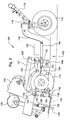
- Figs. 1-3 show a first embodiment of aerator 100 having a flexible frame 102.
- the flexible frame may include a first or forward frame section 104 linked to second or rear frame section 106 at hinge or pivot point 108.
- the first and second frame sections are supported for movement over the ground by a single steerable wheel 110 mounted to the first frame section, which may or may not be driven, and a pair of driven wheels 112 mounted to the second frame section.
- pivot point 108 is located between the first and second frame sections, and provides a horizontal pivot axis perpendicular to the flexible frame aerator's direction of travel.
- the first frame section 104 may have a neck 114 extending upwardly therefrom, and the single steerable wheel may be carried in a pivotal yoke 116 that can rotate about a vertical pivot axis attached to the neck.
- An upwardly and forwardly extending handle assembly 118 may be coupled to the pivotal yoke that carries the front wheel, and may include operator controls that are connected to an electronic vehicle control unit 120. An operator may walk ahead of the flexible frame aerator and steer the vehicle by using the handle assembly to pivot the single steerable front wheel about the vertical pivot axis.
- coring head 122 may be mounted on the second frame section 106 at the rear of the flexible frame aerator, either behind the rear drive wheels and tires, between the rear drive wheels and tires, or adjacent the rear axle(s).
- the coring head may carry a plurality of tine assemblies 124 that reciprocate up and down by rotation of crankshaft 126.
- Each tine assembly may have a plurality of hollow or solid coring tines 128 that are driven into the ground and produce holes for the purpose of aerating the turf.
- Each tine assembly may include a rubber dampener system that absorbs the forward motion of the aerator to help improve hole quality by minimizing hole elongation.
- the coring head may be raised to a transport position or lowered to a coring position using an electrohydraulic lift and lower system.
- An electric motor turns a hydraulic pump to engage a hydraulic cylinder for raising and lowering the coring head that is supported by arms 127 on pivot axis 129. In Figs. 1-3 , the coring head is shown in the lowered position.
- the flexible frame aerator may include one or more turf guards 130 which are slotted plates that slide along the ground surface.
- the turf guard(s) may be attached to turf guard bracket 132 which is aligned transversely to the flexible frame aerator's direction of travel and may be pivotably attached to the frame.
- Each turf guard may have a plurality of slots 134 through which the hollow coring tines reciprocate to make holes in the turf.
- the turf guard holds the turf in place so that when the tines pull out of the ground, the turf around each hole does not lift with them.
- the turf guard may be spring loaded to provide positive and firm support for the tines as they pull out of the ground, and the pressure may be adjusted to lighter tension for soft conditions, or greater tension for firm conditions.
- the turf guard may be constructed of plastic or metal, and the bottom of the turf guard may be beveled to help slide along the ground surface as the flexible frame aerator travels, without grabbing back edges of the holes.
- turf guard 130 and turf guard bracket 132 are pivotably mounted to sub frame 133.
- the turf guard sub frame 133 may be mounted to rear frame member 135 using lost motion linkage 137.
- the linkage may be used to raise or lower the turf guard sub frame together with the coring head, so that the turf guard may be moved between a transport position and a coring position.
- the turf guard while the turf guard is in the coring position, it pivots on axis 136 either in a first direction when encountering a hill or rise, or in a second direction when encountering a dip in the ground surface.
- the pivot axis is horizontal and perpendicular to the direction of travel of the machine.
- the turf guard may be mechanically linked to ground slope sensor 138 that senses angular change or displacement.
- the ground slope sensor may be a potentiometer, an encoder, a Hall sensor or other device that provides output relating to the angular change or displacement of the turf guard. As the turf guard encounters a slope and pivots on axis 136, it moves the sensor an amount corresponding to the change in slope.
- the output from the ground slope sensor may be provided directly to frame flex actuator 140 which flexes the vehicle frame in relation to the change in slope.
- the ground slope sensor may be linked to a hydraulic valve that controls a hydraulic frame flex actuator.
- the turf guard may be connected to ground slope sensor 138 through arms 139, and the sensor may be a potentiometer that provides an output signal regarding the slope to vehicle control unit 120.
- the output signal may be based on the angular position or inclination of the turf guard, which may be provided to the vehicle control unit at regular intervals such as every 10 milliseconds.
- the turf guard travel may be 29,5275 cm (11.625 inches) over 35 degrees at the rear tip
- the ground sensing potentiometer may have an input voltage of 5 VDC and provide an analog input to the vehicle control unit, which is then converted by the vehicle control unit to a digital quantity representing turf guard travel in counts per inch.
- the senor may be attached to the same portion of the frame as the coring head, but not necessarily attached to the coring head.
- the sensor may be any ground following device attached to the first or second frame sections of the flexible frame aerator for sensing changes in slope of the surface being aerated.
- the sensor may include a ground following roller attached to the flexible frame aerator, instead of a sliding turf guard.
- vehicle control unit 120 may use input from ground sensor 138 to determine how much to flex the aerator frame. More specifically, the vehicle control unit may be programmed and configured to flex the frame sufficiently to assure that the coring tines enter and exit the ground perpendicular to the ground surface, regardless of the slope of the ground surface. For example, the vehicle control unit may flex the frame such that the second frame section, where the coring head is mounted, is parallel to the ground.
- vehicle control unit 120 may provide commands to frame flex actuator 140 to flex the aerator frame.
- the commands from the vehicle control unit are based on ground sensor inputs as it encounters a rise or fall of the ground surface.
- the frame flex actuator may be a hydraulic cylinder which may extend and retract between the first and second frame sections, or an electric actuator that may flex the first and second frame sections with respect to each other.
- the frame flex actuator may flex the frame about horizontal pivot axis 108 that is transverse to the flexible frame aerator's direction of travel.
- the flexible frame aerator may include frame flex sensor 142 which may be positioned between the first and second frame sections.
- the frame flex sensor may be a potentiometer, encoder, Hall effect sensor or other device that senses angular displacement.
- the frame flex sensor may be connected through arms 143 to the frame and may provide signals to indicate the angular position of the first frame section relative to the second frame section.
- the frame flex sensor may provide output to vehicle control unit 120.
- the frame flex sensor travel distance may be about plus or minus 5,08 cm (2 inches), and plus or minus about 10 degrees, from a neutral position
- the frame flex potentiometer may have an input voltage of 5 VDC and provide an analog input to the vehicle control unit, which is then converted by the vehicle control unit to a digital quantity representing turf guard travel in counts per inch.
- the flexible frame aerator may have an internal combustion engine, one or more batteries, and/or any other power source that may be used to operate coring head 122 and provide traction drive for the rear wheels.
- the internal combustion engine may also drive an alternator to generate electric power, a mechanical or hydrostatic transmission to connect each power source to one or more of the rear wheels.
- a pump may supply pressurized fluid to a single hydraulic motor or pair of hydraulic motors for rotating the rear wheels. If the flexible frame aerator has an electric traction drive system, an electric drive motor on each rear wheel may be connected by cables to batteries or the electric power supply.
- the vehicle control unit checks if the vehicle is in core mode by reading inputs from the operator controls. If the vehicle is not in the core mode, the vehicle control unit provides a stop frame flex command in block 202, turning off the frame flex actuator. If the operator control inputs show the vehicle is in core mode, the vehicle control unit checks if the core mode interlocks are set in block 203. Examples of core mode interlocks include an operator presence system and parking brake. If the core mode interlocks are not set, the vehicle control unit provides a stop frame flex command in block 202. If the core mode interlocks are set, the vehicle control unit reads the input of the ground sensor in block 204.
- the vehicle control unit determines if the ground sensor input is above, within, or below a pre-specified neutral range in block 205.
- the ground sensor may be a potentiometer that senses the angular position of the pivoting turf guard.
- the neutral range may be a vertical displacement of plus or minus about 0,635 cm (1 ⁇ 4 inch) from zero, or an angular displacement of plus or minus between about 2,54 cm (1 degree) and about 2 degrees from zero.
- the neutral range may be provided so that noise does not result in a false indication of a change in slope.
- the vehicle control unit determines if the frame position sensor is either above or below a pre-specified lower limit in block 206.
- the lower limit for a potentiometer sensing the angular position of the first frame section relative to the second frame section may be a linear distance of about 5,08 cm (2 inches), or about 10 degrees, below a neutral position. If the frame position sensor is above the lower limit, the vehicle control unit sends a command to adjust the flex frame actuator down in block 207. If the frame position sensor is below the lower limit, the vehicle control unit provides a command to stop the flex frame actuator in block 208 and then returns to block 202.
- the vehicle control unit commands the flex frame actuator to stop in block 208 and then returns to block 202.
- the vehicle control unit determines if the frame position sensor is either above or below a pre-specified upper limit in block 209.
- the upper limit for a potentiometer sensing the angular position of the first frame section relative to the second frame section may be a linear distance of about 5,08 cm (2 inches), or about 10 degrees, above a neutral position. If the frame position sensor is below the upper limit, the vehicle control unit sends a command to adjust the flex frame actuator up in block 210. If the frame position sensor is above the upper limit, the vehicle control unit commands the flex frame actuator to stop in block 208 and then returns to block 202.
Landscapes
- Life Sciences & Earth Sciences (AREA)
- Engineering & Computer Science (AREA)
- Mechanical Engineering (AREA)
- Soil Sciences (AREA)
- Environmental Sciences (AREA)
- Soil Working Implements (AREA)
Abstract
Description
- This invention relates to aerators for aerating ground surfaces. More specifically, the invention relates to an aerator that provides holes with more consistent depth that are perpendicular to sloped or undulating ground surfaces such as golf courses.
- Aerators are commonly used for maintaining landscaped ground surfaces including turf. The term "turf" refers to grass and other material which is specifically grown for sporting activities and is used, for example, to form golf course greens. Aerators on these types of surfaces have tines that repeatedly penetrate the ground surface, forming a plurality of holes so that the ground surface is aerated, to improve growth of the grass or other material and enhance the condition of the surface for playing purposes.
- In conducting this type of aeration of turf surfaces, the neatness of the holes made by the aerator tines can significantly affect the overall result. For example, in the case of golf greens and the like where the vegetation is short, a hole with rough edges or too large a hole can cause spot erosion, resulting in an undesirable dimple in the ground surface. This effect is aggravated when forward movement of the aerator differs from the speed of the coring head over the ground surface, causing the tines to rake across or break the ground surface.
- To minimize rough edges of the holes, aerators may be designed to keep the tines substantially vertical for entry and withdrawal from horizontal ground surfaces. For example, aerators may have flywheels that drive the upper ends of tine supports in a circular path, and the lower ends in a reciprocating motion of repeated penetrations into the ground. Link arms can pivot to compensate for forward motion of the machine. At each part of the cycle when the tines are withdrawn from the ground surface, the link arms may position the tines in a substantially vertical position for the next cycle of penetration into the ground. Tines are generally cylindrical and produce holes by pulling up plugs or cylindrical cores of soil as the tines move by rotation of the flywheel.
- Holes produced by aerator tines may be substantially vertical, and perpendicular to ground surfaces, when ground surfaces are horizontal. However, the holes may not be perpendicular to undulating or sloped surfaces. For example, golf courses may have undulations or steep slopes in need of aeration. While an aerator travels over undulations or slopes, the coring head may not be perpendicular to the ground surface and, as a result, the tines may enter and/or exit the ground at angles that are not perpendicular to the ground surface. As a result, the holes are not perpendicular to the ground surface, and may have rough edges and be subject to erosion. Additionally, if the tines are not perpendicular to the ground surface, they do not provide uniform hole depth. Nor do the tines provide uniform spacing between the holes.
- The problem of tines that are not perpendicular to the ground surface also may be due to wider coring heads that are positioned rearwardly of the axle of the supporting wheels. If a coring head is mounted behind the supporting axle of the aerator, and the aerator's wheels ride over a rise in ground contour before the tines fully penetrate the ground, the holes will have a reduced depth. Conversely, if the wheels ride over a dip as the tines penetrate the ground, the tines will produce deeper holes.
-
US Patent 7,293,612 relates to a Walk Aerator with Ground Following Coring Head designed to adjust the vertical position of the coring head relative to the frame in response to changes in ground contour. If the skid assembly rotates sufficiently out of its horizontal position, a pivotal connecting rod attached to the skid assembly causes a switch actuator to depress either of a pair of limit switches. Each limit switch may actuate a hydraulic cylinder to raise or lower the height of the coring head on the frame. As the coring head moves up or down, however, the tines may not be perpendicular to the ground surface. - An aerator is needed that can produce holes that are perpendicular to undulating or sloped ground surfaces, and that have uniform depth and spacing.
- It is therefore the object of the present invention to comply with this need.
- This object is met according to the invention by the teaching of claim 1, while features developing the solution in an advantageous manner are set forth in the further claims.
- Such an aerator may produce holes perpendicular to undulating or sloped ground surfaces, with uniform depth and spacing. The aerator may have a coring head with plurality of tines that move by a reciprocating motion to repeatedly penetrate a ground surface. The coring head may be mounted on a flexible frame having a horizontal pivot axis. A flex frame actuator may be provided to flex the frame on the horizontal pivot axis in response to electronic signals from a ground sensor so that the tines penetrate the ground surface at an angle that is perpendicular to the ground surface.
- According to a first embodiment an aerator may comprise a coring head having a plurality of tines that move by a reciprocating motion to repeatedly penetrate a ground surface; a flexible frame on which the coring head is mounted; the flexible frame having a horizontal pivot axis; and a flex frame actuator to flex the frame on the horizontal pivot axis in response to signals from a ground sensor so that the tines penetrate the ground surface at an angle that is perpendicular to the ground surface.
- The ground sensor may slide along the ground surface and pivot in response to slope changes of the ground surface.
- The flex frame actuator may be a hydraulic cylinder.
- The aerator may further comprise a flex frame sensor that provides signals indicating how much the frame has flexed.
- The flexible frame may include a forward section and a reverse section on which the coring head is mounted.
- In another embodiment an aerator may comprise a first frame section connected to a second frame section on a horizontal pivot axis; a ground sensor attached to one of the first frame section and second frame section and providing output regarding a change in slope of a ground surface; a flex frame actuator connected between the first frame section and the second frame section; the flex frame actuator flexing the frame to an angular position in response to the output from the ground sensor.
- The aerator may further comprise a vehicle control unit receiving the output from the ground sensor and providing angular position commands to the flex frame actuator.
- The aerator may further comprise a frame flex sensor connected between the first frame section and the second frame section and providing output to the vehicle control unit regarding the angular position of the first frame section relative to the second frame section.
- The flex frame actuator may be a hydraulic cylinder.
- The flex frame actuator may be an electric actuator.
- The flex frame actuator may flex only if the output from the ground sensor is outside a neutral range.
- The ground sensor may be a turf guard that slides along the ground surface and pivots on a horizontal axis.
- The flex frame actuator may flex only if the output from the ground sensor is above a lower limit and below an upper limit.
- According to another embodiment an aerator may comprise a pair of frame sections linked together at a horizontal pivot axis; one of the frame sections supporting a coring head; a ground sensor pivotably attached to one of the frame sections so that the ground sensor pivots in response to changes in slope and provides an electronic signal relating to the magnitude of the change; and an electronic control unit receiving the electronic signal and using that electronic signal to provide commands to a flex frame actuator that pivots the pair of frame sections with respect to each other.
- The flex frame actuator may pivot the pair of frame sections to align the coring head to be parallel to the ground surface.
- The flex frame actuator may be a hydraulic cylinder.
- The flex frame actuator may be an electric actuator.
- The aerator may further comprise a flex frame sensor pivotably attached between the pair of frame sections.
- Embodiments of the invention described below are shown in the drawings, in which:
- Fig. 1
- is a side view of an aerator having a flexible frame according to a first embodiment of the invention, with the ground sensor within the neutral range and the flex frame in a un-flexed position.
- Fig. 2
- is a side view of an aerator having a flexible frame according to the first embodiment, with the ground sensor below the neutral range and the flex frame adjusted upwardly.
- Fig.3
- is a side view of an aerator having a flexible frame according to the first embodiment, with the ground sensor above the neutral range and the flex frame adjusted downwardly.
- Fig. 4
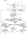
- is a flowchart of a system for flexing an aerator frame according to the first embodiment.
-
Figs. 1-3 show a first embodiment ofaerator 100 having aflexible frame 102. The flexible frame may include a first orforward frame section 104 linked to second orrear frame section 106 at hinge orpivot point 108. The first and second frame sections are supported for movement over the ground by a singlesteerable wheel 110 mounted to the first frame section, which may or may not be driven, and a pair of drivenwheels 112 mounted to the second frame section. - In one embodiment,
pivot point 108 is located between the first and second frame sections, and provides a horizontal pivot axis perpendicular to the flexible frame aerator's direction of travel. Thefirst frame section 104 may have aneck 114 extending upwardly therefrom, and the single steerable wheel may be carried in apivotal yoke 116 that can rotate about a vertical pivot axis attached to the neck. An upwardly and forwardly extendinghandle assembly 118 may be coupled to the pivotal yoke that carries the front wheel, and may include operator controls that are connected to an electronicvehicle control unit 120. An operator may walk ahead of the flexible frame aerator and steer the vehicle by using the handle assembly to pivot the single steerable front wheel about the vertical pivot axis. - In one embodiment,
coring head 122 may be mounted on thesecond frame section 106 at the rear of the flexible frame aerator, either behind the rear drive wheels and tires, between the rear drive wheels and tires, or adjacent the rear axle(s). The coring head may carry a plurality oftine assemblies 124 that reciprocate up and down by rotation ofcrankshaft 126. Each tine assembly may have a plurality of hollow orsolid coring tines 128 that are driven into the ground and produce holes for the purpose of aerating the turf. Each tine assembly may include a rubber dampener system that absorbs the forward motion of the aerator to help improve hole quality by minimizing hole elongation. The coring head may be raised to a transport position or lowered to a coring position using an electrohydraulic lift and lower system. An electric motor turns a hydraulic pump to engage a hydraulic cylinder for raising and lowering the coring head that is supported byarms 127 onpivot axis 129. InFigs. 1-3 , the coring head is shown in the lowered position. - In one embodiment, the flexible frame aerator may include one or
more turf guards 130 which are slotted plates that slide along the ground surface. The turf guard(s) may be attached toturf guard bracket 132 which is aligned transversely to the flexible frame aerator's direction of travel and may be pivotably attached to the frame. Each turf guard may have a plurality ofslots 134 through which the hollow coring tines reciprocate to make holes in the turf. The turf guard holds the turf in place so that when the tines pull out of the ground, the turf around each hole does not lift with them. The turf guard may be spring loaded to provide positive and firm support for the tines as they pull out of the ground, and the pressure may be adjusted to lighter tension for soft conditions, or greater tension for firm conditions. The turf guard may be constructed of plastic or metal, and the bottom of the turf guard may be beveled to help slide along the ground surface as the flexible frame aerator travels, without grabbing back edges of the holes. - In one embodiment,
turf guard 130 andturf guard bracket 132 are pivotably mounted tosub frame 133. The turfguard sub frame 133 may be mounted torear frame member 135 using lostmotion linkage 137. The linkage may be used to raise or lower the turf guard sub frame together with the coring head, so that the turf guard may be moved between a transport position and a coring position. - In one embodiment, while the turf guard is in the coring position, it pivots on
axis 136 either in a first direction when encountering a hill or rise, or in a second direction when encountering a dip in the ground surface. The pivot axis is horizontal and perpendicular to the direction of travel of the machine. - In one embodiment, the turf guard may be mechanically linked to
ground slope sensor 138 that senses angular change or displacement. For example, the ground slope sensor may be a potentiometer, an encoder, a Hall sensor or other device that provides output relating to the angular change or displacement of the turf guard. As the turf guard encounters a slope and pivots onaxis 136, it moves the sensor an amount corresponding to the change in slope. - In one embodiment, the output from the ground slope sensor may be provided directly to
frame flex actuator 140 which flexes the vehicle frame in relation to the change in slope. For example, the ground slope sensor may be linked to a hydraulic valve that controls a hydraulic frame flex actuator. - In one embodiment, the turf guard may be connected to
ground slope sensor 138 througharms 139, and the sensor may be a potentiometer that provides an output signal regarding the slope tovehicle control unit 120. The output signal may be based on the angular position or inclination of the turf guard, which may be provided to the vehicle control unit at regular intervals such as every 10 milliseconds. For example, the turf guard travel may be 29,5275 cm (11.625 inches) over 35 degrees at the rear tip, and the ground sensing potentiometer may have an input voltage of 5 VDC and provide an analog input to the vehicle control unit, which is then converted by the vehicle control unit to a digital quantity representing turf guard travel in counts per inch. - Alternatively, instead of a ground slope sensor linked to the turf guard, the sensor may be attached to the same portion of the frame as the coring head, but not necessarily attached to the coring head. Thus, the sensor may be any ground following device attached to the first or second frame sections of the flexible frame aerator for sensing changes in slope of the surface being aerated. For example, the sensor may include a ground following roller attached to the flexible frame aerator, instead of a sliding turf guard.
- In one embodiment,
vehicle control unit 120 may use input fromground sensor 138 to determine how much to flex the aerator frame. More specifically, the vehicle control unit may be programmed and configured to flex the frame sufficiently to assure that the coring tines enter and exit the ground perpendicular to the ground surface, regardless of the slope of the ground surface. For example, the vehicle control unit may flex the frame such that the second frame section, where the coring head is mounted, is parallel to the ground. - In one embodiment,
vehicle control unit 120 may provide commands to frameflex actuator 140 to flex the aerator frame. The commands from the vehicle control unit are based on ground sensor inputs as it encounters a rise or fall of the ground surface. The frame flex actuator may be a hydraulic cylinder which may extend and retract between the first and second frame sections, or an electric actuator that may flex the first and second frame sections with respect to each other. The frame flex actuator may flex the frame abouthorizontal pivot axis 108 that is transverse to the flexible frame aerator's direction of travel. - In one embodiment, the flexible frame aerator may include
frame flex sensor 142 which may be positioned between the first and second frame sections. The frame flex sensor may be a potentiometer, encoder, Hall effect sensor or other device that senses angular displacement. The frame flex sensor may be connected througharms 143 to the frame and may provide signals to indicate the angular position of the first frame section relative to the second frame section. The frame flex sensor may provide output tovehicle control unit 120. For example, the frame flex sensor travel distance may be about plus or minus 5,08 cm (2 inches), and plus or minus about 10 degrees, from a neutral position, and the frame flex potentiometer may have an input voltage of 5 VDC and provide an analog input to the vehicle control unit, which is then converted by the vehicle control unit to a digital quantity representing turf guard travel in counts per inch. - In one embodiment, the flexible frame aerator may have an internal combustion engine, one or more batteries, and/or any other power source that may be used to operate
coring head 122 and provide traction drive for the rear wheels. The internal combustion engine may also drive an alternator to generate electric power, a mechanical or hydrostatic transmission to connect each power source to one or more of the rear wheels. In the case of a hydrostatic transmission, a pump may supply pressurized fluid to a single hydraulic motor or pair of hydraulic motors for rotating the rear wheels. If the flexible frame aerator has an electric traction drive system, an electric drive motor on each rear wheel may be connected by cables to batteries or the electric power supply. - A preferred system of operating the flexible frame aerator is shown in the flowchart of
Fig. 4 . Inblock 201, the vehicle control unit checks if the vehicle is in core mode by reading inputs from the operator controls. If the vehicle is not in the core mode, the vehicle control unit provides a stop frame flex command inblock 202, turning off the frame flex actuator. If the operator control inputs show the vehicle is in core mode, the vehicle control unit checks if the core mode interlocks are set inblock 203. Examples of core mode interlocks include an operator presence system and parking brake. If the core mode interlocks are not set, the vehicle control unit provides a stop frame flex command inblock 202. If the core mode interlocks are set, the vehicle control unit reads the input of the ground sensor inblock 204. - The vehicle control unit determines if the ground sensor input is above, within, or below a pre-specified neutral range in
block 205. For example, the ground sensor may be a potentiometer that senses the angular position of the pivoting turf guard. The neutral range may be a vertical displacement of plus or minus about 0,635 cm (¼ inch) from zero, or an angular displacement of plus or minus between about 2,54 cm (1 degree) and about 2 degrees from zero. The neutral range may be provided so that noise does not result in a false indication of a change in slope. - If the ground sensor position is above the neutral range, the vehicle control unit determines if the frame position sensor is either above or below a pre-specified lower limit in
block 206. For example, the lower limit for a potentiometer sensing the angular position of the first frame section relative to the second frame section may be a linear distance of about 5,08 cm (2 inches), or about 10 degrees, below a neutral position. If the frame position sensor is above the lower limit, the vehicle control unit sends a command to adjust the flex frame actuator down inblock 207. If the frame position sensor is below the lower limit, the vehicle control unit provides a command to stop the flex frame actuator inblock 208 and then returns to block 202. - If the ground sensor position is within the neutral range, the vehicle control unit commands the flex frame actuator to stop in
block 208 and then returns to block 202. - If the ground sensor position is lower than the neutral range, the vehicle control unit determines if the frame position sensor is either above or below a pre-specified upper limit in
block 209. For example, the upper limit for a potentiometer sensing the angular position of the first frame section relative to the second frame section may be a linear distance of about 5,08 cm (2 inches), or about 10 degrees, above a neutral position. If the frame position sensor is below the upper limit, the vehicle control unit sends a command to adjust the flex frame actuator up inblock 210. If the frame position sensor is above the upper limit, the vehicle control unit commands the flex frame actuator to stop inblock 208 and then returns to block 202. - Having described the preferred embodiment, it will become apparent that various modifications can be made without departing from the scope of the invention as defined in the accompanying claims.
Claims (5)
- An aerator (100) comprising a coring head (122) having a plurality of tines (128) that move by a reciprocating motion to repeatedly penetrate a ground surface; characterized by a flexible frame (102) on which the coring head (122) is mounted; the flexible frame (102) having a horizontal pivot axis; and a flex frame actuator (140) to flex the frame (102) on the horizontal pivot axis in response to signals from a ground sensor (138) so that the tines (128) penetrate the ground surface at an angle that is perpendicular to the ground surface.
- The aerator according to claim 1, characterized in that the ground sensor (138) slides along the ground surface and pivots in response to slope changes of the ground surface.
- The aerator according to claim 1 or 2, characterized in that the flex frame actuator (140) is a hydraulic cylinder.
- The aerator according to one of the previous claims, characterized by a flex frame sensor (142) that provides signals indicating how much the frame (102) has flexed.
- The aerator according to one of the previous claims, characterized in that the flexible frame (102) includes a forward section (104) and a reverse section (106) on which the coring head is mounted (122).
Applications Claiming Priority (1)
| Application Number | Priority Date | Filing Date | Title |
|---|---|---|---|
| US12/713,755 US8255126B2 (en) | 2010-02-26 | 2010-02-26 | Aerator having flexible frame |
Publications (2)
| Publication Number | Publication Date |
|---|---|
| EP2361490A1 true EP2361490A1 (en) | 2011-08-31 |
| EP2361490B1 EP2361490B1 (en) | 2013-01-16 |
Family
ID=43921012
Family Applications (1)
| Application Number | Title | Priority Date | Filing Date |
|---|---|---|---|
| EP11154043A Active EP2361490B1 (en) | 2010-02-26 | 2011-02-10 | Aerator having a flexible frame |
Country Status (2)
| Country | Link |
|---|---|
| US (1) | US8255126B2 (en) |
| EP (1) | EP2361490B1 (en) |
Cited By (2)
| Publication number | Priority date | Publication date | Assignee | Title |
|---|---|---|---|---|
| CN108347875A (en) * | 2015-09-22 | 2018-07-31 | 诺瓦克拉夫特有限公司 | soil treatment device |
| GB2610931A (en) * | 2021-07-30 | 2023-03-22 | The Toro Co | Turf aerator |
Families Citing this family (11)
| Publication number | Priority date | Publication date | Assignee | Title |
|---|---|---|---|---|
| US8925643B2 (en) | 2012-03-30 | 2015-01-06 | Deere & Company | Aerator with coring depth adjustment |
| US8827000B2 (en) | 2012-03-30 | 2014-09-09 | Deere & Company | Aerator with low fuel level control |
| US8800677B2 (en) | 2012-03-30 | 2014-08-12 | Deere & Company | Aerator hole spacing control with lockout |
| FI124565B (en) * | 2012-05-31 | 2014-10-15 | Ponsse Oyj | Stabilization of forestry work unit |
| US8657023B2 (en) * | 2012-06-20 | 2014-02-25 | Deere & Company | Multiple-section agricultural implement |
| US8955610B1 (en) * | 2013-03-15 | 2015-02-17 | Billy Goat Industries, Inc. | Turf aerators and tine assemblies for same |
| US9510497B2 (en) | 2014-02-03 | 2016-12-06 | Deere & Company | Aerator with active turf calibration of ground sensor |
| US10206321B2 (en) | 2014-02-04 | 2019-02-19 | Deere & Company | Aerator with variable delay of coring head |
| US10143123B2 (en) * | 2016-01-21 | 2018-12-04 | John L. Shaw | Core collector |
| US11917937B2 (en) * | 2017-07-10 | 2024-03-05 | Precision Planting Llc | Seed injector |
| US11272652B2 (en) | 2018-03-23 | 2022-03-15 | Briggs & Stratton, Llc | Turf aerators and assemblies for same |
Citations (3)
| Publication number | Priority date | Publication date | Assignee | Title |
|---|---|---|---|---|
| WO2004016070A2 (en) * | 2002-03-15 | 2004-02-26 | Deere & Company | Cultivating device |
| US7293612B1 (en) | 2002-11-12 | 2007-11-13 | The Toro Company | Walk aerator with ground following coring head |
| US20080257571A1 (en) * | 2007-03-13 | 2008-10-23 | William Anthony Keane | Frame Orientation Control Device for an Aeration Apparatus |
Family Cites Families (11)
| Publication number | Priority date | Publication date | Assignee | Title |
|---|---|---|---|---|
| US5704200A (en) * | 1995-11-06 | 1998-01-06 | Control Concepts, Inc. | Agricultural harvester ground tracking control system and method using fuzzy logic |
| AUPN642695A0 (en) * | 1995-11-08 | 1995-11-30 | Deere & Company | Cultivating machine |
| US5797458A (en) * | 1997-02-05 | 1998-08-25 | Deere & Company | Aerator control mechanism |
| GB2333219B (en) * | 1998-01-14 | 2002-10-16 | Turfmech Machinery Ltd | Aeration machine |
| US6948568B2 (en) * | 2001-04-06 | 2005-09-27 | Deere & Company | Cultivator for aerating a ground surface |
| US6701699B2 (en) * | 2001-04-25 | 2004-03-09 | The Toro Company | On-board vehicle jacking apparatus and methods of using same |
| US6615570B2 (en) * | 2001-06-28 | 2003-09-09 | Deere & Company | Header position control with forward contour prediction |
| DE10227484A1 (en) * | 2002-06-19 | 2004-02-26 | Claas Selbstfahrende Erntemaschinen Gmbh | Device and method for controlling the position of a harvesting device of agricultural harvesting machines |
| US7267181B2 (en) * | 2002-08-15 | 2007-09-11 | Deere & Company | Cultivating device |
| US7730960B1 (en) * | 2005-02-09 | 2010-06-08 | The Toro Company | Turf aeration device |
| US7894957B2 (en) * | 2008-01-28 | 2011-02-22 | Textron Innovations Inc. | Dynamic tactical steering feedback |
-
2010
- 2010-02-26 US US12/713,755 patent/US8255126B2/en active Active
-
2011
- 2011-02-10 EP EP11154043A patent/EP2361490B1/en active Active
Patent Citations (3)
| Publication number | Priority date | Publication date | Assignee | Title |
|---|---|---|---|---|
| WO2004016070A2 (en) * | 2002-03-15 | 2004-02-26 | Deere & Company | Cultivating device |
| US7293612B1 (en) | 2002-11-12 | 2007-11-13 | The Toro Company | Walk aerator with ground following coring head |
| US20080257571A1 (en) * | 2007-03-13 | 2008-10-23 | William Anthony Keane | Frame Orientation Control Device for an Aeration Apparatus |
Cited By (5)
| Publication number | Priority date | Publication date | Assignee | Title |
|---|---|---|---|---|
| CN108347875A (en) * | 2015-09-22 | 2018-07-31 | 诺瓦克拉夫特有限公司 | soil treatment device |
| CN108347875B (en) * | 2015-09-22 | 2021-10-29 | 诺瓦克拉夫特有限公司 | Soil treatment device |
| GB2610931A (en) * | 2021-07-30 | 2023-03-22 | The Toro Co | Turf aerator |
| GB2610931B (en) * | 2021-07-30 | 2024-01-17 | The Toro Co | Turf aerator |
| US12268110B2 (en) | 2021-07-30 | 2025-04-08 | The Toro Company | Turf aerator |
Also Published As
| Publication number | Publication date |
|---|---|
| US20110213530A1 (en) | 2011-09-01 |
| EP2361490B1 (en) | 2013-01-16 |
| US8255126B2 (en) | 2012-08-28 |
Similar Documents
| Publication | Publication Date | Title |
|---|---|---|
| EP2361490B1 (en) | Aerator having a flexible frame | |
| EP2644014B1 (en) | Aerator with coring depth adjustment | |
| US10206321B2 (en) | Aerator with variable delay of coring head | |
| EP2572564B1 (en) | Aerator hole spacing control | |
| CA2147699C (en) | Grass cutting mower | |
| US9510497B2 (en) | Aerator with active turf calibration of ground sensor | |
| EP2260686A1 (en) | Hole spacing control system and aerator | |
| US8800677B2 (en) | Aerator hole spacing control with lockout | |
| GB2540012A (en) | Height of cut control system | |
| EP2644013B1 (en) | Aerator with low fuel level control | |
| WO2014145632A1 (en) | Apparatus and method for aerating soil | |
| US6948568B2 (en) | Cultivator for aerating a ground surface | |
| CN212138418U (en) | Electronic weeding ditching all-in-one that loosens soil | |
| JP2002101704A (en) | Farm work machine | |
| KR200396448Y1 (en) | A weeder with riding and Walking of interrow and hill spacing | |
| KR200396450Y1 (en) | A weeder with riding interrow and hill spacing | |
| CA2442976C (en) | A cultivator for aerating a ground surface | |
| US20080011494A1 (en) | Grooming Apparatus for Artificial Racetrack Surface | |
| KR100529362B1 (en) | A weeder with embarking type weeding in interrow and hill spacing of flooded paddy field | |
| JPH06507542A (en) | Blade for soil leveling device | |
| EP2727448A1 (en) | Walk behind aerator hydrostatic traction drive system | |
| JP4692390B2 (en) | Seedling machine wave breaker | |
| JP5255356B2 (en) | 畝 Molding machine | |
| JPH05207812A (en) | Lodged grain calm dividing and handling machine | |
| AU2922302A (en) | A cultivating device for aerating a ground surface |
Legal Events
| Date | Code | Title | Description |
|---|---|---|---|
| PUAI | Public reference made under article 153(3) epc to a published international application that has entered the european phase |
Free format text: ORIGINAL CODE: 0009012 |
|
| AK | Designated contracting states |
Kind code of ref document: A1 Designated state(s): AL AT BE BG CH CY CZ DE DK EE ES FI FR GB GR HR HU IE IS IT LI LT LU LV MC MK MT NL NO PL PT RO RS SE SI SK SM TR |
|
| AX | Request for extension of the european patent |
Extension state: BA ME |
|
| 17P | Request for examination filed |
Effective date: 20120229 |
|
| 17Q | First examination report despatched |
Effective date: 20120326 |
|
| REG | Reference to a national code |
Ref country code: DE Ref legal event code: R079 Ref document number: 602011000750 Country of ref document: DE Free format text: PREVIOUS MAIN CLASS: A01B0045020000 Ipc: B62D0053020000 |
|
| RIC1 | Information provided on ipc code assigned before grant |
Ipc: B62D 53/02 20060101AFI20120713BHEP Ipc: A01B 45/02 20060101ALI20120713BHEP |
|
| GRAP | Despatch of communication of intention to grant a patent |
Free format text: ORIGINAL CODE: EPIDOSNIGR1 |
|
| GRAS | Grant fee paid |
Free format text: ORIGINAL CODE: EPIDOSNIGR3 |
|
| GRAA | (expected) grant |
Free format text: ORIGINAL CODE: 0009210 |
|
| AK | Designated contracting states |
Kind code of ref document: B1 Designated state(s): AL AT BE BG CH CY CZ DE DK EE ES FI FR GB GR HR HU IE IS IT LI LT LU LV MC MK MT NL NO PL PT RO RS SE SI SK SM TR |
|
| REG | Reference to a national code |
Ref country code: GB Ref legal event code: FG4D |
|
| REG | Reference to a national code |
Ref country code: CH Ref legal event code: EP |
|
| REG | Reference to a national code |
Ref country code: IE Ref legal event code: FG4D |
|
| REG | Reference to a national code |
Ref country code: AT Ref legal event code: REF Ref document number: 593730 Country of ref document: AT Kind code of ref document: T Effective date: 20130215 Ref country code: CH Ref legal event code: EP |
|
| REG | Reference to a national code |
Ref country code: DE Ref legal event code: R096 Ref document number: 602011000750 Country of ref document: DE Effective date: 20130314 |
|
| REG | Reference to a national code |
Ref country code: AT Ref legal event code: MK05 Ref document number: 593730 Country of ref document: AT Kind code of ref document: T Effective date: 20130116 |
|
| REG | Reference to a national code |
Ref country code: NL Ref legal event code: VDEP Effective date: 20130116 |
|
| REG | Reference to a national code |
Ref country code: LT Ref legal event code: MG4D |
|
| PG25 | Lapsed in a contracting state [announced via postgrant information from national office to epo] |
Ref country code: LT Free format text: LAPSE BECAUSE OF FAILURE TO SUBMIT A TRANSLATION OF THE DESCRIPTION OR TO PAY THE FEE WITHIN THE PRESCRIBED TIME-LIMIT Effective date: 20130116 Ref country code: IS Free format text: LAPSE BECAUSE OF FAILURE TO SUBMIT A TRANSLATION OF THE DESCRIPTION OR TO PAY THE FEE WITHIN THE PRESCRIBED TIME-LIMIT Effective date: 20130516 Ref country code: BG Free format text: LAPSE BECAUSE OF FAILURE TO SUBMIT A TRANSLATION OF THE DESCRIPTION OR TO PAY THE FEE WITHIN THE PRESCRIBED TIME-LIMIT Effective date: 20130416 Ref country code: NO Free format text: LAPSE BECAUSE OF FAILURE TO SUBMIT A TRANSLATION OF THE DESCRIPTION OR TO PAY THE FEE WITHIN THE PRESCRIBED TIME-LIMIT Effective date: 20130416 Ref country code: AT Free format text: LAPSE BECAUSE OF FAILURE TO SUBMIT A TRANSLATION OF THE DESCRIPTION OR TO PAY THE FEE WITHIN THE PRESCRIBED TIME-LIMIT Effective date: 20130116 Ref country code: ES Free format text: LAPSE BECAUSE OF FAILURE TO SUBMIT A TRANSLATION OF THE DESCRIPTION OR TO PAY THE FEE WITHIN THE PRESCRIBED TIME-LIMIT Effective date: 20130427 Ref country code: SE Free format text: LAPSE BECAUSE OF FAILURE TO SUBMIT A TRANSLATION OF THE DESCRIPTION OR TO PAY THE FEE WITHIN THE PRESCRIBED TIME-LIMIT Effective date: 20130116 Ref country code: BE Free format text: LAPSE BECAUSE OF FAILURE TO SUBMIT A TRANSLATION OF THE DESCRIPTION OR TO PAY THE FEE WITHIN THE PRESCRIBED TIME-LIMIT Effective date: 20130116 |
|
| PG25 | Lapsed in a contracting state [announced via postgrant information from national office to epo] |
Ref country code: PL Free format text: LAPSE BECAUSE OF FAILURE TO SUBMIT A TRANSLATION OF THE DESCRIPTION OR TO PAY THE FEE WITHIN THE PRESCRIBED TIME-LIMIT Effective date: 20130116 Ref country code: FI Free format text: LAPSE BECAUSE OF FAILURE TO SUBMIT A TRANSLATION OF THE DESCRIPTION OR TO PAY THE FEE WITHIN THE PRESCRIBED TIME-LIMIT Effective date: 20130116 Ref country code: PT Free format text: LAPSE BECAUSE OF FAILURE TO SUBMIT A TRANSLATION OF THE DESCRIPTION OR TO PAY THE FEE WITHIN THE PRESCRIBED TIME-LIMIT Effective date: 20130516 Ref country code: NL Free format text: LAPSE BECAUSE OF FAILURE TO SUBMIT A TRANSLATION OF THE DESCRIPTION OR TO PAY THE FEE WITHIN THE PRESCRIBED TIME-LIMIT Effective date: 20130116 Ref country code: SI Free format text: LAPSE BECAUSE OF FAILURE TO SUBMIT A TRANSLATION OF THE DESCRIPTION OR TO PAY THE FEE WITHIN THE PRESCRIBED TIME-LIMIT Effective date: 20130116 Ref country code: LV Free format text: LAPSE BECAUSE OF FAILURE TO SUBMIT A TRANSLATION OF THE DESCRIPTION OR TO PAY THE FEE WITHIN THE PRESCRIBED TIME-LIMIT Effective date: 20130116 Ref country code: GR Free format text: LAPSE BECAUSE OF FAILURE TO SUBMIT A TRANSLATION OF THE DESCRIPTION OR TO PAY THE FEE WITHIN THE PRESCRIBED TIME-LIMIT Effective date: 20130417 |
|
| PG25 | Lapsed in a contracting state [announced via postgrant information from national office to epo] |
Ref country code: RS Free format text: LAPSE BECAUSE OF FAILURE TO SUBMIT A TRANSLATION OF THE DESCRIPTION OR TO PAY THE FEE WITHIN THE PRESCRIBED TIME-LIMIT Effective date: 20130116 Ref country code: MC Free format text: LAPSE BECAUSE OF NON-PAYMENT OF DUE FEES Effective date: 20130228 Ref country code: HR Free format text: LAPSE BECAUSE OF FAILURE TO SUBMIT A TRANSLATION OF THE DESCRIPTION OR TO PAY THE FEE WITHIN THE PRESCRIBED TIME-LIMIT Effective date: 20130116 |
|
| PG25 | Lapsed in a contracting state [announced via postgrant information from national office to epo] |
Ref country code: SK Free format text: LAPSE BECAUSE OF FAILURE TO SUBMIT A TRANSLATION OF THE DESCRIPTION OR TO PAY THE FEE WITHIN THE PRESCRIBED TIME-LIMIT Effective date: 20130116 Ref country code: RO Free format text: LAPSE BECAUSE OF FAILURE TO SUBMIT A TRANSLATION OF THE DESCRIPTION OR TO PAY THE FEE WITHIN THE PRESCRIBED TIME-LIMIT Effective date: 20130116 Ref country code: DK Free format text: LAPSE BECAUSE OF FAILURE TO SUBMIT A TRANSLATION OF THE DESCRIPTION OR TO PAY THE FEE WITHIN THE PRESCRIBED TIME-LIMIT Effective date: 20130116 Ref country code: CZ Free format text: LAPSE BECAUSE OF FAILURE TO SUBMIT A TRANSLATION OF THE DESCRIPTION OR TO PAY THE FEE WITHIN THE PRESCRIBED TIME-LIMIT Effective date: 20130116 Ref country code: EE Free format text: LAPSE BECAUSE OF FAILURE TO SUBMIT A TRANSLATION OF THE DESCRIPTION OR TO PAY THE FEE WITHIN THE PRESCRIBED TIME-LIMIT Effective date: 20130116 |
|
| PLBE | No opposition filed within time limit |
Free format text: ORIGINAL CODE: 0009261 |
|
| REG | Reference to a national code |
Ref country code: FR Ref legal event code: ST Effective date: 20131031 |
|
| STAA | Information on the status of an ep patent application or granted ep patent |
Free format text: STATUS: NO OPPOSITION FILED WITHIN TIME LIMIT |
|
| PG25 | Lapsed in a contracting state [announced via postgrant information from national office to epo] |
Ref country code: CY Free format text: LAPSE BECAUSE OF FAILURE TO SUBMIT A TRANSLATION OF THE DESCRIPTION OR TO PAY THE FEE WITHIN THE PRESCRIBED TIME-LIMIT Effective date: 20130116 |
|
| REG | Reference to a national code |
Ref country code: IE Ref legal event code: MM4A |
|
| 26N | No opposition filed |
Effective date: 20131017 |
|
| PG25 | Lapsed in a contracting state [announced via postgrant information from national office to epo] |
Ref country code: IT Free format text: LAPSE BECAUSE OF FAILURE TO SUBMIT A TRANSLATION OF THE DESCRIPTION OR TO PAY THE FEE WITHIN THE PRESCRIBED TIME-LIMIT Effective date: 20130116 |
|
| PG25 | Lapsed in a contracting state [announced via postgrant information from national office to epo] |
Ref country code: IE Free format text: LAPSE BECAUSE OF NON-PAYMENT OF DUE FEES Effective date: 20130210 Ref country code: FR Free format text: LAPSE BECAUSE OF NON-PAYMENT OF DUE FEES Effective date: 20130318 Ref country code: AL Free format text: LAPSE BECAUSE OF FAILURE TO SUBMIT A TRANSLATION OF THE DESCRIPTION OR TO PAY THE FEE WITHIN THE PRESCRIBED TIME-LIMIT Effective date: 20130116 |
|
| REG | Reference to a national code |
Ref country code: DE Ref legal event code: R097 Ref document number: 602011000750 Country of ref document: DE Effective date: 20131017 |
|
| PG25 | Lapsed in a contracting state [announced via postgrant information from national office to epo] |
Ref country code: MT Free format text: LAPSE BECAUSE OF FAILURE TO SUBMIT A TRANSLATION OF THE DESCRIPTION OR TO PAY THE FEE WITHIN THE PRESCRIBED TIME-LIMIT Effective date: 20130116 |
|
| REG | Reference to a national code |
Ref country code: CH Ref legal event code: PL |
|
| PG25 | Lapsed in a contracting state [announced via postgrant information from national office to epo] |
Ref country code: LI Free format text: LAPSE BECAUSE OF NON-PAYMENT OF DUE FEES Effective date: 20140228 Ref country code: CH Free format text: LAPSE BECAUSE OF NON-PAYMENT OF DUE FEES Effective date: 20140228 |
|
| PG25 | Lapsed in a contracting state [announced via postgrant information from national office to epo] |
Ref country code: SM Free format text: LAPSE BECAUSE OF FAILURE TO SUBMIT A TRANSLATION OF THE DESCRIPTION OR TO PAY THE FEE WITHIN THE PRESCRIBED TIME-LIMIT Effective date: 20130116 |
|
| PG25 | Lapsed in a contracting state [announced via postgrant information from national office to epo] |
Ref country code: TR Free format text: LAPSE BECAUSE OF FAILURE TO SUBMIT A TRANSLATION OF THE DESCRIPTION OR TO PAY THE FEE WITHIN THE PRESCRIBED TIME-LIMIT Effective date: 20130116 |
|
| PG25 | Lapsed in a contracting state [announced via postgrant information from national office to epo] |
Ref country code: MK Free format text: LAPSE BECAUSE OF FAILURE TO SUBMIT A TRANSLATION OF THE DESCRIPTION OR TO PAY THE FEE WITHIN THE PRESCRIBED TIME-LIMIT Effective date: 20130116 Ref country code: LU Free format text: LAPSE BECAUSE OF NON-PAYMENT OF DUE FEES Effective date: 20130210 Ref country code: HU Free format text: LAPSE BECAUSE OF FAILURE TO SUBMIT A TRANSLATION OF THE DESCRIPTION OR TO PAY THE FEE WITHIN THE PRESCRIBED TIME-LIMIT; INVALID AB INITIO Effective date: 20110210 |
|
| PGFP | Annual fee paid to national office [announced via postgrant information from national office to epo] |
Ref country code: DE Payment date: 20230119 Year of fee payment: 13 |
|
| REG | Reference to a national code |
Ref country code: DE Ref legal event code: R119 Ref document number: 602011000750 Country of ref document: DE |
|
| PG25 | Lapsed in a contracting state [announced via postgrant information from national office to epo] |
Ref country code: DE Free format text: LAPSE BECAUSE OF NON-PAYMENT OF DUE FEES Effective date: 20240903 |
|
| PG25 | Lapsed in a contracting state [announced via postgrant information from national office to epo] |
Ref country code: DE Free format text: LAPSE BECAUSE OF NON-PAYMENT OF DUE FEES Effective date: 20240903 |
|
| PGFP | Annual fee paid to national office [announced via postgrant information from national office to epo] |
Ref country code: GB Payment date: 20260227 Year of fee payment: 16 |