EP2360951A1 - A method for adaptively matching microphones of a hearing system as well as a hearing system - Google Patents
A method for adaptively matching microphones of a hearing system as well as a hearing system Download PDFInfo
- Publication number
- EP2360951A1 EP2360951A1 EP10159667A EP10159667A EP2360951A1 EP 2360951 A1 EP2360951 A1 EP 2360951A1 EP 10159667 A EP10159667 A EP 10159667A EP 10159667 A EP10159667 A EP 10159667A EP 2360951 A1 EP2360951 A1 EP 2360951A1
- Authority
- EP
- European Patent Office
- Prior art keywords
- microphones
- hearing system
- determining
- tdoa
- sound source
- Prior art date
- Legal status (The legal status is an assumption and is not a legal conclusion. Google has not performed a legal analysis and makes no representation as to the accuracy of the status listed.)
- Granted
Links
Images
Classifications
-
- H—ELECTRICITY
- H04—ELECTRIC COMMUNICATION TECHNIQUE
- H04R—LOUDSPEAKERS, MICROPHONES, GRAMOPHONE PICK-UPS OR LIKE ACOUSTIC ELECTROMECHANICAL TRANSDUCERS; ELECTRIC HEARING AIDS; PUBLIC ADDRESS SYSTEMS
- H04R29/00—Monitoring arrangements; Testing arrangements
- H04R29/004—Monitoring arrangements; Testing arrangements for microphones
- H04R29/005—Microphone arrays
- H04R29/006—Microphone matching
-
- H—ELECTRICITY
- H04—ELECTRIC COMMUNICATION TECHNIQUE
- H04R—LOUDSPEAKERS, MICROPHONES, GRAMOPHONE PICK-UPS OR LIKE ACOUSTIC ELECTROMECHANICAL TRANSDUCERS; ELECTRIC HEARING AIDS; PUBLIC ADDRESS SYSTEMS
- H04R25/00—Electric hearing aids
- H04R25/40—Arrangements for obtaining a desired directivity characteristic
- H04R25/407—Circuits for combining signals of a plurality of transducers
-
- H—ELECTRICITY
- H04—ELECTRIC COMMUNICATION TECHNIQUE
- H04R—LOUDSPEAKERS, MICROPHONES, GRAMOPHONE PICK-UPS OR LIKE ACOUSTIC ELECTROMECHANICAL TRANSDUCERS; ELECTRIC HEARING AIDS; PUBLIC ADDRESS SYSTEMS
- H04R3/00—Circuits for transducers
- H04R3/005—Circuits for transducers for combining the signals of two or more microphones
Definitions
- the present invention is related to a method for adaptively matching microphones of a hearing system as well as to a hearing system.
- Hearing systems utilize two microphones to do beamforming.
- Beamforming is known as a very effective way to improve speech intelligibility for hearing impaired persons wearing a hearing system.
- the microphones resp. the signal paths up to a beamformer processing unit have to be well matched in phase and magnitude over the frequency range of interest.
- the present invention is first directed to a method for adaptively matching microphones of a hearing system, the method comprising the steps of:
- the performance of the beamformer can be improved to a large extent. This is in particular true with regard to the low frequency behavior of the beamformer.
- static calibration methods to match the microphones in production or during the fitting process can be avoided.
- the step of determining the true direction comprises limiting a first frequency range to a section in which a good matching of the microphones is expected, the first frequency range being in particular above 1 kHz.
- the step of determining an estimated direction comprises limiting a second frequency range to a section in which the matching of the microphones is to be improved, the second frequency range being in particular below 1 kHz.
- the hearing system comprises a binaural hearing device with at least two microphones to be matched, and wherein an ipsi-lateral microphone and a co-lateral microphone are used in the step of determining the true direction.
- two ipsi-lateral microphones are used in the step of determining an estimated direction.
- Further embodiments of the method according to the present invention further comprise the step of checking whether a single sound source is present, particularly having at least a predefined signal-to-noise ratio.
- a speech detector is used to determine whether a single broadband sound source is present.
- a single sound source can easily be determined.
- Such a sound source is sufficiently broadband and originates from a single location. Therefore, it can very be used for adapting the microphones.
- all steps are performed during regular operation of the hearing system.
- the present invention is directed to a hearing system comprising:
- the means for determining the true direction comprise frequency limiting means for limiting a first frequency range to a section in which a good matching of the microphones is expected, the first frequency range being in particular above 1 kHz.
- the means for determining the estimated direction comprise frequency limiting means for limiting a second frequency range to a section in which the matching of the microphones is to be improved, the second frequency range being in particular below 1 kHz.
- Still further embodiments of the hearing system according to the present invention further comprise means for checking whether a single sound source is present, particularly having at least a predefined signal-to-noise ratio.
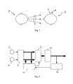
- Fig. 1 shows a common situation which is suitable to perform a microphone matching according to the present invention.
- the situation is characterized in that a hearing system user 1 is confronted with a single sound source 2.
- the single sound source 2 is a person speaking to the hearing system user 1.
- the hearing system user 1 wears a hearing device in one of his ears - also known as monaural hearing system -, the hearing device comprising two microphones 3 and 4.
- the microphones 3 and 4 or a signal path up to a beamformer, respectively, have to be matched in phase and magnitude over a frequency range of interest to enable effective and accurate beamforming.
- a phase matching is particularly important for lower frequencies, i.e.
- phase matching for the microphones 3 and 4 can be reduced to a frequency range below 1 kHz.
- the present invention makes use of the knowledge that the two microphones 3 and 4 are well matched in a first frequency range, e.g. frequencies above 1 kHz.
- a first frequency range e.g. frequencies above 1 kHz.
- a true direction tDOA of the sound source 2 in relation to the position of the hearing system user 1 can be determined in the first frequency range. Due to the fact that the microphones 3 and 4 are well matched in the first frequency range, the true direction tDOA determined in this first frequency range can be regarded as precise.
- an estimated direction eDOA is determined in the second frequency range using the same microphones 3 and 4.
- a correction factor ⁇ is obtained by comparing the true direction tDOA and the estimated direction eDOA, the correction factor ⁇ being a measure of how well the microphones 3 and 4 are matched in the second frequency range.
- the effectively measured estimated direction eDOA in the second frequency range can now get corrected by the correction factor ⁇ leading to the same direction as measured in the first frequency range.
- the correction itself can be performed by applying a suitable filter in time domain or frequency domain in front of a beamformer or within the beamformer itself or before/within any signal processing algorithm being sensitive to phase mismatching of the input sources.
- Such algorithms include source localization methods, for example, utilizing a cross correlation or mutual time delay of the microphone signals, respectively.
- a monaural hearing system with a microphone distance of 10 mm.
- a sound source 2 - e.g. a speech source - is detected in the first frequency range with a true direction tDOA of 0°.
- the same sound source 2 is detected in the second frequency range, e.g. at 300 Hz with a time delay of 44ps.
- Such a bias time delay corresponds to a phase shift of approximately 1.6° at 300Hz.
- This phase shift can now get implemented with an allpass filter, in the frequency domain by multiplication of the audio signal with a complex exponential function or with another suitable filter. If the measured arrival delay is smaller than 29 ⁇ s, the corresponding correction factor ⁇ may get applied on the back microphone signal.
- Fig. 2 showing a block diagram of a front end of the monaural hearing system worn by the hearing system user 1 of Fig. 1 .
- Output signals of the microphones 3 and 4 are fed to a frequency separation unit 8, in which the audio signals are separated into different frequency bands.
- fat lines indicate vectors of frequency band separated signals.
- the information of the frequency separation unit 8 is fed to a correction unit 9 as well as to a adapting unit 10, in which the correction factor ⁇ is determined as has already been described.
- the block diagram of Fig. 2 can be changed without departing from the concept of the present invention.
- the adapting unit 10 to determine the true or estimated direction tDOA or eDOA can be placed after the correction unit 9 or act in a feedback fashion.
- the frequency band separation in the frequency separation unit 8 can be done by time domain filters, a Fourier transform (FFT) or other suitable methods.
- FFT Fourier transform
- the level and phase matching in the correction unit 9 as well as the beamforming algorithm in the beamformer unit 11 can be performed in time domain or in frequency domain.
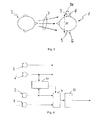
- Fig. 3 again shows a common situation as has already been presented in connection with Fig. 1 and the monaural hearing system.
- Fig. 3 now refers to a binaural hearing system that comprises a left and a right hearing device with its microphones 3, 4 and 5, 6, respectively.
- the microphone distance is significantly larger than for a single hearing device, i.e. for a monaural hearing system, the effect of phase mismatching is also significantly less severe on localization errors.
- a distance D1 between the microphones 3 and 4 of the same hearing device is approximately 10 mm
- a distance D2 between microphones 3, 5 and 4, 6, respectively is approximately 170 mm.
- the beamforming may contain a forward looking cardioid (with a null direction towards 180°) and a blocking matrix (backward facing cardioid) with a null direction towards 0°.
Landscapes
- Health & Medical Sciences (AREA)
- General Health & Medical Sciences (AREA)
- Otolaryngology (AREA)
- Physics & Mathematics (AREA)
- Engineering & Computer Science (AREA)
- Acoustics & Sound (AREA)
- Signal Processing (AREA)
- Circuit For Audible Band Transducer (AREA)
- Measurement Of Mechanical Vibrations Or Ultrasonic Waves (AREA)
Abstract
Description
- The present invention is related to a method for adaptively matching microphones of a hearing system as well as to a hearing system.
- Hearing systems utilize two microphones to do beamforming. Beamforming is known as a very effective way to improve speech intelligibility for hearing impaired persons wearing a hearing system. To enable effective beamforming, the microphones resp. the signal paths up to a beamformer processing unit have to be well matched in phase and magnitude over the frequency range of interest.
- Unfortunately, the available microphones are not sufficiently matched in phase to achieve a satisfactory beamforming performance at low frequencies without further matching methods. Common deviations are up to 80µs group delay difference at low frequencies, i.e. at 100 Hz. In order to obtain a satisfactory result when using a beamformer, the group delay difference must be below 10µs, preferably even below 5µs.
- Known methods that try to improve a beamformer algorithm by microphone matching use a standard procedure or a model of a possible error situation. Wrong assumption for the model or insufficient models result in an imprecise beamformer. In this connection, reference is made to
US-7 027 607 ,US-7 155 019 ,US-6 385 323 ,US-2007/0183610 A1 ,US-2007/0258597 A1 ,US-2005/0244018 A1 andUS-6 272 229 . - Therefore, it is one object of the present invention to provide a method for matching microphones that does at least not have one of the disadvantages of known solutions.
- The present invention is defined by the steps of
claim 1. Further embodiments as well as a hearing system are defined in further claims. - The present invention is first directed to a method for adaptively matching microphones of a hearing system, the method comprising the steps of:
- determining a true direction towards a sound source,
- determining an estimated direction towards the sound source using microphones of the hearing system,
- comparing the true direction with the estimated direction to obtain a correction factor,
- applying the correction factor to the signals of the microphones of the hearing system in order to reduce a difference between the true direction and a corrected estimated direction obtained via corrected microphone signals.
- Thereby, the performance of the beamformer can be improved to a large extent. This is in particular true with regard to the low frequency behavior of the beamformer. In addition, static calibration methods to match the microphones in production or during the fitting process can be avoided.
- In an embodiment of the method according to the present invention, the step of determining the true direction comprises limiting a first frequency range to a section in which a good matching of the microphones is expected, the first frequency range being in particular above 1 kHz.
- In further embodiments of the method according to the present invention, the step of determining an estimated direction comprises limiting a second frequency range to a section in which the matching of the microphones is to be improved, the second frequency range being in particular below 1 kHz.
- In further embodiments of the method according to the present invention, the hearing system comprises a single hearing device with at least two microphones to be matched.
- In still further embodiments of the method according to the present invention, the hearing system comprises a binaural hearing device with at least two microphones to be matched, and wherein an ipsi-lateral microphone and a co-lateral microphone are used in the step of determining the true direction.
- In further embodiments of the method according to the present invention, two ipsi-lateral microphones are used in the step of determining an estimated direction.
- Further embodiments of the method according to the present invention further comprise the step of checking whether a single sound source is present, particularly having at least a predefined signal-to-noise ratio.
- In further embodiments of the method according to the present invention, a speech detector is used to determine whether a single broadband sound source is present. With the speech detector, a single sound source can easily be determined. Such a sound source is sufficiently broadband and originates from a single location. Therefore, it can very be used for adapting the microphones.
- In still further embodiments of the method according to the present invention, all steps are performed during regular operation of the hearing system.
- Furthermore, the present invention is directed to a hearing system comprising:
- at least two microphones generating input signals,
- means for determining a true direction towards a sound source,
- means for determining an estimated direction towards the sound source using at least two of the at least two microphones,
- means for comparing the true direction with the estimated direction to obtain a correction factor,
- means for applying the correction factor to the input signals of the microphones in order to reduce a difference between the true direction and a corrected estimated direction obtained via corrected input signals.
- In an embodiment of the hearing system according to the present invention, the means for determining the true direction comprise frequency limiting means for limiting a first frequency range to a section in which a good matching of the microphones is expected, the first frequency range being in particular above 1 kHz.
- In further embodiments of the hearing system according to the present invention, the means for determining the estimated direction comprise frequency limiting means for limiting a second frequency range to a section in which the matching of the microphones is to be improved, the second frequency range being in particular below 1 kHz.
- Further embodiments of the hearing system according to the present invention comprise a single hearing device with at least two microphones to be matched.
- Further embodiments of the hearing system according to the present invention comprise
- a binaural hearing device with at least two microphones (3, 4, 5, 6) to be matched,
- an ipsi-lateral microphone (3, 4) and a co-lateral microphone (5, 6) are used to determine the true direction (tDOA).
- Further embodiments of the hearing system according to the present invention comprise two ipsi-lateral microphones to determine the estimated direction.
- Still further embodiments of the hearing system according to the present invention further comprise means for checking whether a single sound source is present, particularly having at least a predefined signal-to-noise ratio.
- Further embodiments of the hearing system according to the present invention comprise a speech detector is used to determine whether a single broadband sound source is present.
- It is pointed out that the present invention is directed to every possible combination of the above-mentioned embodiments. Only those combinations are excluded which would result in a contradiction.
- The present invention will be further described in the following by referring to drawings showing exemplified embodiments of the present invention.
- Fig. 1
- shows a situation with a hearing system user wearing a hearing device in one ear and a person as a single sound source,
- Fig. 2
- shows a schematic block diagram of an input section of the hearing device used by the hearing system user of
Fig. 1 , - Fig. 3
- shows a situation with a hearing system user wearing a binaural hearing device and the sound source of
Fig. 1 , and - Fig. 4
- shows a schematic block diagram of an input section of the binaural hearing device used by the hearing system user of
Fig. 3 . -
Fig. 1 shows a common situation which is suitable to perform a microphone matching according to the present invention. The situation is characterized in that ahearing system user 1 is confronted with asingle sound source 2. Thesingle sound source 2 is a person speaking to thehearing system user 1. Thehearing system user 1 wears a hearing device in one of his ears - also known as monaural hearing system -, the hearing device comprising twomicrophones microphones microphones - In a first embodiment, the present invention makes use of the knowledge that the two
microphones single sound source 2 is present having a sufficiently broad spectrum, i.e. a frequency range that encompasses at least a section of the first frequency range as well as a second frequency range, in which microphone matching must be performed, a true direction tDOA of thesound source 2 in relation to the position of thehearing system user 1 can be determined in the first frequency range. Due to the fact that themicrophones - In a further step, an estimated direction eDOA is determined in the second frequency range using the
same microphones sound source 2 is still at the same location, a correction factor α is obtained by comparing the true direction tDOA and the estimated direction eDOA, the correction factor α being a measure of how well themicrophones microphones microphones - In a further embodiment of the present invention, it is checked whether a
single sound source 2 is present in order to obtain improved matching results for themicrophones - The
sound source 2 must be broadband, i.e. at least covering a section of the first frequency range as well as a section of the second frequency range; and - The signal-to-noise-(SNR) ratio must be sufficiently high over the background noise.
- Speech in a quiet surrounding is a
sound source 2 that fulfills the requirement of being sufficiently broadband and, in addition, has a sufficiently high signal-to-noise or SNR ratio over the background noise. Therefore, and in a further embodiment of the present invention, a speech detector is applied that is used to detect this favorable sound source for the matching process. Speech detectors are well known in the art and are known to be reliable. Once a speech detector has detected a single speech source assound source 2, the true direction tDOA is determined at mid frequencies, i.e. in the first frequency range defined by 1 to 4 kHz, for example. From knowing that thissound source 2 originates from a single source, namely the mouth of the person speaking, it can be inferred that the incoming sound energy at lower frequencies, i.e. in the second frequency range, comes from the same direction, namely the true direction tDOA. The effectively measured estimated direction eDOA in the second frequency range can now get corrected by the correction factor α leading to the same direction as measured in the first frequency range. The correction itself can be performed by applying a suitable filter in time domain or frequency domain in front of a beamformer or within the beamformer itself or before/within any signal processing algorithm being sensitive to phase mismatching of the input sources. Such algorithms include source localization methods, for example, utilizing a cross correlation or mutual time delay of the microphone signals, respectively. - In the following, an example is given for a monaural hearing system with a microphone distance of 10 mm. In case a sound source 2 - e.g. a speech source - is detected in the first frequency range with a true direction tDOA of 0°. A signal arrival delay between the
microphones 
- The
same sound source 2 is detected in the second frequency range, e.g. at 300 Hz with a time delay of 44ps. A corresponding correction factor α of 44ps - 29µs = 15µs bias time delay has to get applied to the front microphone in this frequency band. Such a bias time delay corresponds to a phase shift of approximately 1.6° at 300Hz. This phase shift can now get implemented with an allpass filter, in the frequency domain by multiplication of the audio signal with a complex exponential function or with another suitable filter. If the measured arrival delay is smaller than 29µs, the corresponding correction factor α may get applied on the back microphone signal. - The above-mentioned processing steps are further described by referring to
Fig. 2 showing a block diagram of a front end of the monaural hearing system worn by thehearing system user 1 ofFig. 1 . Output signals of themicrophones unit 10, in which the correction factor α is determined as has already been described. The correction factor α is fed to the correction unit 9 in order that a possible mismatching of themicrophones beamformer unit 11 to obtain directional information that is later processed in a signal processing unit (not shown inFig. 2 ). Furthermore, a front/back detector unit 12 is provided that is used to generate information whether asound source 2 is in the front or in the back of the hearing device user 1 (Fig. 1 ). This information is important for the adaptingunit 10 and must therefore be taken into account while determining the correction factor α. - It is clear to the skilled in the art that the block diagram of
Fig. 2 can be changed without departing from the concept of the present invention. For example, the adaptingunit 10 to determine the true or estimated direction tDOA or eDOA can be placed after the correction unit 9 or act in a feedback fashion. - The frequency band separation in the frequency separation unit 8 can be done by time domain filters, a Fourier transform (FFT) or other suitable methods. Similarly, the level and phase matching in the correction unit 9 as well as the beamforming algorithm in the
beamformer unit 11 can be performed in time domain or in frequency domain. -
Fig. 3 again shows a common situation as has already been presented in connection withFig. 1 and the monaural hearing system.Fig. 3 now refers to a binaural hearing system that comprises a left and a right hearing device with itsmicrophones microphones microphones sound source 2 in front of thehearing system user 1 up to approx. ±10º of the true direction at low frequencies. This can be done for each time-frequency slot. - Thus, by utilizing the contra-
lateral microphone sound source 2 for each frequency band of interest (e.g. for all bands < 1kHz) and each time slot. If asound source 2 is present in front of thehearing system user 1, i.e. at 0° ±10° than the monaural phase matching algorithm is computed with the knowledge of the known true direction tDOA. The time constant of the actual phase matching algorithm can still be slow, i.e. in the order of hours or even days to account for the slow changes in phase matching without introducing unwanted oscillations. Thus, such measurement or correction values can also get stored in a non-volatile memory and used as initialization values after initializing or boot-up of the hearing system. - The above-mentioned processing steps are further described by referring to
Fig. 4 showing a schematic block diagram of a front end of the binaural hearing system worn by thehearing system user 1 ofFig. 3 . Themicrophones microphones beamformer unit 11 that follows the correction unit 9 down the signal path. In contrast to the embodiment according toFig. 2 , the adaptingunit 10 ofFig. 4 now receives input signals of a contra-lateral microphone 5 and the ipsi-lateral microphone 4. As explained above, the contra-lateral microphone 5 is - due to its distance D2 to the ipsi-lateral microphone 4 - better suited for determining the true direction tDOA of asound source 2. - It is to be noted that in the method used in connection with monaural hearing systems as well as in the method used in connection with binaural hearing systems, the beamforming may contain a forward looking cardioid (with a null direction towards 180°) and a blocking matrix (backward facing cardioid) with a null direction towards 0°.
- Due to local effects of wearing a beamformer close to the head of the hearing system user, the microphone signals for the forward looking cardioid and the backward facing cardioid have to be matched differently. Thus, the method explained in relation to the monaural hearing system may not only use a "speech from front" detector, but additionally or alternatively also a "speech from back" detector. Likewise, the method explained in relation to the binaural hearing system may have an additional or alternative output indicating signals from 180° ±10° incidence direction controlling a second path within the level- and phase matching block for the two different cardioids.
- An additional advantage of the method explained in relation to the binaural hearing system is that not only the two ipsi-lateral microphones can get matched when the true direction tDOA indicates a signal from the front and/or the back, but that the contra-lateral microphones can also get matched to the ipsi-lateral ones when a signal from the front or from the back are detected.
Claims (19)
- A method for adaptively matching microphones (3, 4, 5, 6) of a hearing system, the method comprising the steps of:- determining a true direction (tDOA) towards a sound source (2),- determining an estimated direction (eDOA) towards the sound source (2) using microphones (3, 4, 5, 6) of the hearing system,- comparing the true direction (tDOA) with the estimated direction (eDOA) to obtain a correction factor (α),- applying the correction factor (α) to the signals of the microphones (3, 4, 5, 6) of the hearing system in order to reduce a difference between the true direction (tDOA) and a corrected estimated direction (eDOA) obtained via corrected microphone signals.
- The method of claim 1, wherein the step of determining the true direction (tDOA) comprises limiting a first frequency range to a section in which a good matching of the microphones (3, 4, 5, 6) is expected, the first frequency range being in particular above 1 kHz.
- The method of claim 1 or 2, wherein the step of determining an estimated direction (eDOA) comprises limiting a second frequency range to a section in which the matching of the microphones (3, 4, 5, 6) is to be improved, the second frequency range being in particular below 1 kHz.
- The method of one of the claims 1 to 3, wherein the hearing system comprises a single hearing device with at least two microphones (3, 4) to be matched.
- The method of the claim 1, wherein the hearing system comprises a binaural hearing device with at least two microphones (3, 4, 5, 6) to be matched, and wherein an ipsi-lateral microphone (3, 4) and a co-lateral microphone (5, 6) are used in the step of determining the true direction (tDOA).
- The method of claim 5, wherein two ipsi-lateral microphones (3, 4) are used in the step of determining an estimated direction (eDOA).
- The method of one of the claims 1 to 6, further comprising the step of checking whether a single sound source (2) is present, particularly having at least a predefined signal-to-noise ratio and a predefined spectral range.
- The method of claim 7, wherein a speech detector is used for determining the true direction (tDOA) of the sound source (2).
- The method of one of the claims 1 to 8, wherein all steps are performed during regular operation of the hearing system.
- The method of one of the claims 1 to 9, further comprising the step of storing the correction factor (α) in a non-volatile memory in order to have access to the correction factor (α) for initialization of the hearing system after boot-up.
- A hearing system comprising:- at least two microphones (3, 4, 5, 6) generating input signals,- means for determining a true direction (tDOA) towards a sound source (2),- means for determining an estimated direction (eDOA) towards the sound source (2) using at least two of the at least two microphones (3, 4, 5, 6),- means for comparing the true direction (tDOA) with the estimated direction (eDOA) to obtain a correction factor (α),- means for applying the correction factor (α) to the input signals of the microphones (3, 4, 5, 6) in order to reduce a difference between the true direction (tDOA) and a corrected estimated direction (eDOA) obtained via corrected input signals.
- The hearing system of claim 11, wherein the means for determining the true direction (tDOA) comprise frequency limiting means for limiting a first frequency range to a section in which a good matching of the microphones (3, 4, 5, 6) is expected, the first frequency range being in particular above 1 kHz.
- The hearing system of claim 11 or 12, wherein the means for determining the estimated direction (eDOA) comprise frequency limiting means for limiting a second frequency range to a section in which the matching of the microphones (3, 4, 5, 6) is to be improved, the second frequency range being in particular below 1 kHz.
- The hearing system of one of the claims 11 to 13, comprising a single hearing device with at least two microphones (3, 4) to be matched.
- The hearing system of the claim 11, comprising- a binaural hearing device with at least two microphones (3, 4, 5, 6) to be matched,- an ipsi-lateral microphone (3, 4) and a co-lateral microphone (5, 6) are used to determine the true direction (tDOA).
- The hearing system of claim 11, comprising two ipsi-lateral microphones (3, 4) to determine the estimated direction (eDOA).
- The hearing system of one of the claims 11 to 16, further comprising means for checking whether a single sound source (2) is present, particularly having at least a predefined signal-to-noise ratio and a predefined spectral range.
- The hearing system of claim 16, comprising a speech detector for determining whether a single broadband sound source present.
- The hearing system of one of the claims 11 to 18, comprising a non-volatile memory for storing the correction factor (α) in order to have access to the correction factor (α) for initialization after boot-up.
Applications Claiming Priority (1)
| Application Number | Priority Date | Filing Date | Title |
|---|---|---|---|
| US12/696,110 US8588441B2 (en) | 2010-01-29 | 2010-01-29 | Method for adaptively matching microphones of a hearing system as well as a hearing system |
Publications (2)
| Publication Number | Publication Date |
|---|---|
| EP2360951A1 true EP2360951A1 (en) | 2011-08-24 |
| EP2360951B1 EP2360951B1 (en) | 2013-09-04 |
Family
ID=43755153
Family Applications (1)
| Application Number | Title | Priority Date | Filing Date |
|---|---|---|---|
| EP10159667.4A Active EP2360951B1 (en) | 2010-01-29 | 2010-04-12 | A method for adaptively matching microphones of a hearing system as well as a hearing system |
Country Status (3)
| Country | Link |
|---|---|
| US (1) | US8588441B2 (en) |
| EP (1) | EP2360951B1 (en) |
| DK (1) | DK2360951T3 (en) |
Cited By (1)
| Publication number | Priority date | Publication date | Assignee | Title |
|---|---|---|---|---|
| DE102013207080A1 (en) | 2013-04-19 | 2014-10-23 | Siemens Medical Instruments Pte. Ltd. | Binaural microphone adaptation using your own voice |
Families Citing this family (6)
| Publication number | Priority date | Publication date | Assignee | Title |
|---|---|---|---|---|
| US20130013302A1 (en) | 2011-07-08 | 2013-01-10 | Roger Roberts | Audio input device |
| US9392366B1 (en) | 2013-11-25 | 2016-07-12 | Meyer Sound Laboratories, Incorporated | Magnitude and phase correction of a hearing device |
| US9911416B2 (en) * | 2015-03-27 | 2018-03-06 | Qualcomm Incorporated | Controlling electronic device based on direction of speech |
| AU2016413718A1 (en) * | 2016-07-07 | 2019-02-14 | Meyer Sound Laboratories, Incorporated | Magnitude and phase correction of a hearing device |
| CN106531165A (en) * | 2016-12-15 | 2017-03-22 | 北京塞宾科技有限公司 | Portable smart home voice control system and control method adopting same |
| US20230328465A1 (en) * | 2022-03-25 | 2023-10-12 | Gn Hearing A/S | Method at a binaural hearing device system and a binaural hearing device system |
Citations (11)
| Publication number | Priority date | Publication date | Assignee | Title |
|---|---|---|---|---|
| US5029215A (en) * | 1989-12-29 | 1991-07-02 | At&T Bell Laboratories | Automatic calibrating apparatus and method for second-order gradient microphone |
| US6272229B1 (en) | 1999-08-03 | 2001-08-07 | Topholm & Westermann Aps | Hearing aid with adaptive matching of microphones |
| US6385323B1 (en) | 1998-05-15 | 2002-05-07 | Siemens Audiologische Technik Gmbh | Hearing aid with automatic microphone balancing and method for operating a hearing aid with automatic microphone balancing |
| US20030142836A1 (en) * | 2000-09-29 | 2003-07-31 | Warren Daniel Max | Microphone array having a second order directional pattern |
| EP1489883A2 (en) * | 2004-04-30 | 2004-12-22 | Phonak Ag | Automatic microphone matching |
| US20050244018A1 (en) | 2004-03-05 | 2005-11-03 | Siemens Audiologische Technik Gmbh | Method and device for matching the phases of microphone signals of a directional microphone of a hearing aid |
| US7027607B2 (en) | 2000-09-22 | 2006-04-11 | Gn Resound A/S | Hearing aid with adaptive microphone matching |
| US7155019B2 (en) | 2000-03-14 | 2006-12-26 | Apherma Corporation | Adaptive microphone matching in multi-microphone directional system |
| US20070183610A1 (en) | 2004-10-19 | 2007-08-09 | Widex A/S | System and method for adaptive microphone matching in a hearing aid |
| US20070258597A1 (en) | 2004-08-24 | 2007-11-08 | Oticon A/S | Low Frequency Phase Matching for Microphones |
| US7346176B1 (en) * | 2000-05-11 | 2008-03-18 | Plantronics, Inc. | Auto-adjust noise canceling microphone with position sensor |
-
2010
- 2010-01-29 US US12/696,110 patent/US8588441B2/en not_active Expired - Fee Related
- 2010-04-12 DK DK10159667.4T patent/DK2360951T3/en active
- 2010-04-12 EP EP10159667.4A patent/EP2360951B1/en active Active
Patent Citations (11)
| Publication number | Priority date | Publication date | Assignee | Title |
|---|---|---|---|---|
| US5029215A (en) * | 1989-12-29 | 1991-07-02 | At&T Bell Laboratories | Automatic calibrating apparatus and method for second-order gradient microphone |
| US6385323B1 (en) | 1998-05-15 | 2002-05-07 | Siemens Audiologische Technik Gmbh | Hearing aid with automatic microphone balancing and method for operating a hearing aid with automatic microphone balancing |
| US6272229B1 (en) | 1999-08-03 | 2001-08-07 | Topholm & Westermann Aps | Hearing aid with adaptive matching of microphones |
| US7155019B2 (en) | 2000-03-14 | 2006-12-26 | Apherma Corporation | Adaptive microphone matching in multi-microphone directional system |
| US7346176B1 (en) * | 2000-05-11 | 2008-03-18 | Plantronics, Inc. | Auto-adjust noise canceling microphone with position sensor |
| US7027607B2 (en) | 2000-09-22 | 2006-04-11 | Gn Resound A/S | Hearing aid with adaptive microphone matching |
| US20030142836A1 (en) * | 2000-09-29 | 2003-07-31 | Warren Daniel Max | Microphone array having a second order directional pattern |
| US20050244018A1 (en) | 2004-03-05 | 2005-11-03 | Siemens Audiologische Technik Gmbh | Method and device for matching the phases of microphone signals of a directional microphone of a hearing aid |
| EP1489883A2 (en) * | 2004-04-30 | 2004-12-22 | Phonak Ag | Automatic microphone matching |
| US20070258597A1 (en) | 2004-08-24 | 2007-11-08 | Oticon A/S | Low Frequency Phase Matching for Microphones |
| US20070183610A1 (en) | 2004-10-19 | 2007-08-09 | Widex A/S | System and method for adaptive microphone matching in a hearing aid |
Cited By (3)
| Publication number | Priority date | Publication date | Assignee | Title |
|---|---|---|---|---|
| DE102013207080A1 (en) | 2013-04-19 | 2014-10-23 | Siemens Medical Instruments Pte. Ltd. | Binaural microphone adaptation using your own voice |
| US9565499B2 (en) | 2013-04-19 | 2017-02-07 | Sivantos Pte. Ltd. | Binaural hearing aid system for compensation of microphone deviations based on the wearer's own voice |
| DE102013207080B4 (en) | 2013-04-19 | 2019-03-21 | Sivantos Pte. Ltd. | Binaural microphone adaptation using your own voice |
Also Published As
| Publication number | Publication date |
|---|---|
| EP2360951B1 (en) | 2013-09-04 |
| DK2360951T3 (en) | 2013-12-09 |
| US20110188681A1 (en) | 2011-08-04 |
| US8588441B2 (en) | 2013-11-19 |
Similar Documents
| Publication | Publication Date | Title |
|---|---|---|
| EP2360951B1 (en) | A method for adaptively matching microphones of a hearing system as well as a hearing system | |
| US11638085B2 (en) | System, device and method for assessing a fit quality of an earpiece | |
| EP2916321B1 (en) | Processing of a noisy audio signal to estimate target and noise spectral variances | |
| EP3248393B1 (en) | Hearing assistance system | |
| US9635474B2 (en) | Method of processing a signal in a hearing instrument, and hearing instrument | |
| EP3704874B1 (en) | Method of operating a hearing aid system and a hearing aid system | |
| US20060120540A1 (en) | Method and device for processing an acoustic signal | |
| US10397711B2 (en) | Method of determining objective perceptual quantities of noisy speech signals | |
| CN103907152B (en) | The method and system suppressing for audio signal noise | |
| US10504537B2 (en) | Wind noise measurement | |
| EP1691576A2 (en) | Method to adjust a hearing system, method to operate the hearing system and a hearing system | |
| EP3429230A1 (en) | Hearing device and method with non-intrusive speech intelligibility prediction | |
| WO2020035180A1 (en) | Method of operating an ear level audio system and an ear level audio system | |
| US11057721B2 (en) | Own voice detection in hearing instrument devices | |
| Gößling et al. | RTF-steered binaural MVDR beamforming incorporating multiple external microphones | |
| Marquardt et al. | Perceptually motivated coherence preservation in multi-channel wiener filtering based noise reduction for binaural hearing aids | |
| KR101203926B1 (en) | Noise direction detection method using multi beamformer | |
| US11470429B2 (en) | Method of operating an ear level audio system and an ear level audio system | |
| EP4416937B1 (en) | Method for detecting a direction of arrival of an acoustic target signal | |
| US20250330756A1 (en) | Method for directional signal processing for a hearing instrument and hearing instrument | |
| US11425495B1 (en) | Sound source localization using wave decomposition | |
| Hohmann et al. | Cocktail party processing based on interaural parameters | |
| JP2020201370A (en) | Speaker direction determination program, speaker direction determination method, and speaker direction determination device | |
| Schmitz et al. | On the reduction of masking effects while preserving competing binaural audio streams | |
| HK1135488A (en) | Near-field vector signal enhancement |
Legal Events
| Date | Code | Title | Description |
|---|---|---|---|
| PUAI | Public reference made under article 153(3) epc to a published international application that has entered the european phase |
Free format text: ORIGINAL CODE: 0009012 |
|
| AK | Designated contracting states |
Kind code of ref document: A1 Designated state(s): AT BE BG CH CY CZ DE DK EE ES FI FR GB GR HR HU IE IS IT LI LT LU LV MC MK MT NL NO PL PT RO SE SI SK SM TR |
|
| AX | Request for extension of the european patent |
Extension state: AL BA ME RS |
|
| 17P | Request for examination filed |
Effective date: 20120224 |
|
| GRAP | Despatch of communication of intention to grant a patent |
Free format text: ORIGINAL CODE: EPIDOSNIGR1 |
|
| RIC1 | Information provided on ipc code assigned before grant |
Ipc: H04R 29/00 20060101AFI20130304BHEP |
|
| INTG | Intention to grant announced |
Effective date: 20130328 |
|
| GRAS | Grant fee paid |
Free format text: ORIGINAL CODE: EPIDOSNIGR3 |
|
| GRAA | (expected) grant |
Free format text: ORIGINAL CODE: 0009210 |
|
| AK | Designated contracting states |
Kind code of ref document: B1 Designated state(s): AT BE BG CH CY CZ DE DK EE ES FI FR GB GR HR HU IE IS IT LI LT LU LV MC MK MT NL NO PL PT RO SE SI SK SM TR |
|
| REG | Reference to a national code |
Ref country code: GB Ref legal event code: FG4D |
|
| REG | Reference to a national code |
Ref country code: CH Ref legal event code: EP |
|
| REG | Reference to a national code |
Ref country code: AT Ref legal event code: REF Ref document number: 631044 Country of ref document: AT Kind code of ref document: T Effective date: 20130915 |
|
| REG | Reference to a national code |
Ref country code: IE Ref legal event code: FG4D |
|
| REG | Reference to a national code |
Ref country code: DE Ref legal event code: R096 Ref document number: 602010009952 Country of ref document: DE Effective date: 20131031 |
|
| REG | Reference to a national code |
Ref country code: DK Ref legal event code: T3 Effective date: 20131204 |
|
| REG | Reference to a national code |
Ref country code: AT Ref legal event code: MK05 Ref document number: 631044 Country of ref document: AT Kind code of ref document: T Effective date: 20130904 |
|
| REG | Reference to a national code |
Ref country code: NL Ref legal event code: VDEP Effective date: 20130904 |
|
| PG25 | Lapsed in a contracting state [announced via postgrant information from national office to epo] |
Ref country code: NO Free format text: LAPSE BECAUSE OF FAILURE TO SUBMIT A TRANSLATION OF THE DESCRIPTION OR TO PAY THE FEE WITHIN THE PRESCRIBED TIME-LIMIT Effective date: 20131204 Ref country code: AT Free format text: LAPSE BECAUSE OF FAILURE TO SUBMIT A TRANSLATION OF THE DESCRIPTION OR TO PAY THE FEE WITHIN THE PRESCRIBED TIME-LIMIT Effective date: 20130904 Ref country code: SE Free format text: LAPSE BECAUSE OF FAILURE TO SUBMIT A TRANSLATION OF THE DESCRIPTION OR TO PAY THE FEE WITHIN THE PRESCRIBED TIME-LIMIT Effective date: 20130904 Ref country code: HR Free format text: LAPSE BECAUSE OF FAILURE TO SUBMIT A TRANSLATION OF THE DESCRIPTION OR TO PAY THE FEE WITHIN THE PRESCRIBED TIME-LIMIT Effective date: 20130904 Ref country code: LT Free format text: LAPSE BECAUSE OF FAILURE TO SUBMIT A TRANSLATION OF THE DESCRIPTION OR TO PAY THE FEE WITHIN THE PRESCRIBED TIME-LIMIT Effective date: 20130904 Ref country code: CY Free format text: LAPSE BECAUSE OF FAILURE TO SUBMIT A TRANSLATION OF THE DESCRIPTION OR TO PAY THE FEE WITHIN THE PRESCRIBED TIME-LIMIT Effective date: 20130626 |
|
| REG | Reference to a national code |
Ref country code: NL Ref legal event code: VDEP Effective date: 20130904 |
|
| REG | Reference to a national code |
Ref country code: LT Ref legal event code: MG4D |
|
| PG25 | Lapsed in a contracting state [announced via postgrant information from national office to epo] |
Ref country code: SI Free format text: LAPSE BECAUSE OF FAILURE TO SUBMIT A TRANSLATION OF THE DESCRIPTION OR TO PAY THE FEE WITHIN THE PRESCRIBED TIME-LIMIT Effective date: 20130904 Ref country code: LV Free format text: LAPSE BECAUSE OF FAILURE TO SUBMIT A TRANSLATION OF THE DESCRIPTION OR TO PAY THE FEE WITHIN THE PRESCRIBED TIME-LIMIT Effective date: 20130904 Ref country code: GR Free format text: LAPSE BECAUSE OF FAILURE TO SUBMIT A TRANSLATION OF THE DESCRIPTION OR TO PAY THE FEE WITHIN THE PRESCRIBED TIME-LIMIT Effective date: 20131205 Ref country code: FI Free format text: LAPSE BECAUSE OF FAILURE TO SUBMIT A TRANSLATION OF THE DESCRIPTION OR TO PAY THE FEE WITHIN THE PRESCRIBED TIME-LIMIT Effective date: 20130904 Ref country code: PL Free format text: LAPSE BECAUSE OF FAILURE TO SUBMIT A TRANSLATION OF THE DESCRIPTION OR TO PAY THE FEE WITHIN THE PRESCRIBED TIME-LIMIT Effective date: 20130904 |
|
| PG25 | Lapsed in a contracting state [announced via postgrant information from national office to epo] |
Ref country code: CY Free format text: LAPSE BECAUSE OF FAILURE TO SUBMIT A TRANSLATION OF THE DESCRIPTION OR TO PAY THE FEE WITHIN THE PRESCRIBED TIME-LIMIT Effective date: 20130904 Ref country code: BE Free format text: LAPSE BECAUSE OF FAILURE TO SUBMIT A TRANSLATION OF THE DESCRIPTION OR TO PAY THE FEE WITHIN THE PRESCRIBED TIME-LIMIT Effective date: 20130904 |
|
| PG25 | Lapsed in a contracting state [announced via postgrant information from national office to epo] |
Ref country code: SK Free format text: LAPSE BECAUSE OF FAILURE TO SUBMIT A TRANSLATION OF THE DESCRIPTION OR TO PAY THE FEE WITHIN THE PRESCRIBED TIME-LIMIT Effective date: 20130904 Ref country code: NL Free format text: LAPSE BECAUSE OF FAILURE TO SUBMIT A TRANSLATION OF THE DESCRIPTION OR TO PAY THE FEE WITHIN THE PRESCRIBED TIME-LIMIT Effective date: 20130904 Ref country code: EE Free format text: LAPSE BECAUSE OF FAILURE TO SUBMIT A TRANSLATION OF THE DESCRIPTION OR TO PAY THE FEE WITHIN THE PRESCRIBED TIME-LIMIT Effective date: 20130904 Ref country code: RO Free format text: LAPSE BECAUSE OF FAILURE TO SUBMIT A TRANSLATION OF THE DESCRIPTION OR TO PAY THE FEE WITHIN THE PRESCRIBED TIME-LIMIT Effective date: 20130904 Ref country code: CZ Free format text: LAPSE BECAUSE OF FAILURE TO SUBMIT A TRANSLATION OF THE DESCRIPTION OR TO PAY THE FEE WITHIN THE PRESCRIBED TIME-LIMIT Effective date: 20130904 Ref country code: IS Free format text: LAPSE BECAUSE OF FAILURE TO SUBMIT A TRANSLATION OF THE DESCRIPTION OR TO PAY THE FEE WITHIN THE PRESCRIBED TIME-LIMIT Effective date: 20140104 |
|
| PG25 | Lapsed in a contracting state [announced via postgrant information from national office to epo] |
Ref country code: ES Free format text: LAPSE BECAUSE OF FAILURE TO SUBMIT A TRANSLATION OF THE DESCRIPTION OR TO PAY THE FEE WITHIN THE PRESCRIBED TIME-LIMIT Effective date: 20130904 |
|
| REG | Reference to a national code |
Ref country code: DE Ref legal event code: R097 Ref document number: 602010009952 Country of ref document: DE |
|
| PG25 | Lapsed in a contracting state [announced via postgrant information from national office to epo] |
Ref country code: PT Free format text: LAPSE BECAUSE OF FAILURE TO SUBMIT A TRANSLATION OF THE DESCRIPTION OR TO PAY THE FEE WITHIN THE PRESCRIBED TIME-LIMIT Effective date: 20140106 |
|
| PLBE | No opposition filed within time limit |
Free format text: ORIGINAL CODE: 0009261 |
|
| STAA | Information on the status of an ep patent application or granted ep patent |
Free format text: STATUS: NO OPPOSITION FILED WITHIN TIME LIMIT |
|
| 26N | No opposition filed |
Effective date: 20140605 |
|
| PG25 | Lapsed in a contracting state [announced via postgrant information from national office to epo] |
Ref country code: IT Free format text: LAPSE BECAUSE OF FAILURE TO SUBMIT A TRANSLATION OF THE DESCRIPTION OR TO PAY THE FEE WITHIN THE PRESCRIBED TIME-LIMIT Effective date: 20130904 |
|
| REG | Reference to a national code |
Ref country code: DE Ref legal event code: R097 Ref document number: 602010009952 Country of ref document: DE Effective date: 20140605 |
|
| PG25 | Lapsed in a contracting state [announced via postgrant information from national office to epo] |
Ref country code: LU Free format text: LAPSE BECAUSE OF FAILURE TO SUBMIT A TRANSLATION OF THE DESCRIPTION OR TO PAY THE FEE WITHIN THE PRESCRIBED TIME-LIMIT Effective date: 20140412 Ref country code: MC Free format text: LAPSE BECAUSE OF FAILURE TO SUBMIT A TRANSLATION OF THE DESCRIPTION OR TO PAY THE FEE WITHIN THE PRESCRIBED TIME-LIMIT Effective date: 20130904 |
|
| REG | Reference to a national code |
Ref country code: CH Ref legal event code: PL |
|
| REG | Reference to a national code |
Ref country code: IE Ref legal event code: MM4A |
|
| PG25 | Lapsed in a contracting state [announced via postgrant information from national office to epo] |
Ref country code: CH Free format text: LAPSE BECAUSE OF NON-PAYMENT OF DUE FEES Effective date: 20140430 Ref country code: LI Free format text: LAPSE BECAUSE OF NON-PAYMENT OF DUE FEES Effective date: 20140430 |
|
| PG25 | Lapsed in a contracting state [announced via postgrant information from national office to epo] |
Ref country code: IE Free format text: LAPSE BECAUSE OF NON-PAYMENT OF DUE FEES Effective date: 20140412 |
|
| PG25 | Lapsed in a contracting state [announced via postgrant information from national office to epo] |
Ref country code: MT Free format text: LAPSE BECAUSE OF FAILURE TO SUBMIT A TRANSLATION OF THE DESCRIPTION OR TO PAY THE FEE WITHIN THE PRESCRIBED TIME-LIMIT Effective date: 20130904 |
|
| REG | Reference to a national code |
Ref country code: FR Ref legal event code: PLFP Year of fee payment: 7 |
|
| PG25 | Lapsed in a contracting state [announced via postgrant information from national office to epo] |
Ref country code: SM Free format text: LAPSE BECAUSE OF FAILURE TO SUBMIT A TRANSLATION OF THE DESCRIPTION OR TO PAY THE FEE WITHIN THE PRESCRIBED TIME-LIMIT Effective date: 20130904 |
|
| PG25 | Lapsed in a contracting state [announced via postgrant information from national office to epo] |
Ref country code: BG Free format text: LAPSE BECAUSE OF FAILURE TO SUBMIT A TRANSLATION OF THE DESCRIPTION OR TO PAY THE FEE WITHIN THE PRESCRIBED TIME-LIMIT Effective date: 20130904 |
|
| PG25 | Lapsed in a contracting state [announced via postgrant information from national office to epo] |
Ref country code: TR Free format text: LAPSE BECAUSE OF FAILURE TO SUBMIT A TRANSLATION OF THE DESCRIPTION OR TO PAY THE FEE WITHIN THE PRESCRIBED TIME-LIMIT Effective date: 20130904 Ref country code: HU Free format text: LAPSE BECAUSE OF FAILURE TO SUBMIT A TRANSLATION OF THE DESCRIPTION OR TO PAY THE FEE WITHIN THE PRESCRIBED TIME-LIMIT; INVALID AB INITIO Effective date: 20100412 |
|
| REG | Reference to a national code |
Ref country code: FR Ref legal event code: PLFP Year of fee payment: 8 |
|
| REG | Reference to a national code |
Ref country code: FR Ref legal event code: PLFP Year of fee payment: 9 |
|
| PG25 | Lapsed in a contracting state [announced via postgrant information from national office to epo] |
Ref country code: MK Free format text: LAPSE BECAUSE OF FAILURE TO SUBMIT A TRANSLATION OF THE DESCRIPTION OR TO PAY THE FEE WITHIN THE PRESCRIBED TIME-LIMIT Effective date: 20130904 |
|
| REG | Reference to a national code |
Ref country code: DE Ref legal event code: R084 Ref document number: 602010009952 Country of ref document: DE |
|
| PGFP | Annual fee paid to national office [announced via postgrant information from national office to epo] |
Ref country code: DE Payment date: 20250429 Year of fee payment: 16 |
|
| PGFP | Annual fee paid to national office [announced via postgrant information from national office to epo] |
Ref country code: GB Payment date: 20250428 Year of fee payment: 16 Ref country code: DK Payment date: 20250425 Year of fee payment: 16 |
|
| PGFP | Annual fee paid to national office [announced via postgrant information from national office to epo] |
Ref country code: FR Payment date: 20250425 Year of fee payment: 16 |