EP2360501A1 - Backlight unit and display device having the same - Google Patents
Backlight unit and display device having the same Download PDFInfo
- Publication number
- EP2360501A1 EP2360501A1 EP11150925A EP11150925A EP2360501A1 EP 2360501 A1 EP2360501 A1 EP 2360501A1 EP 11150925 A EP11150925 A EP 11150925A EP 11150925 A EP11150925 A EP 11150925A EP 2360501 A1 EP2360501 A1 EP 2360501A1
- Authority
- EP
- European Patent Office
- Prior art keywords
- optical engine
- backlight unit
- light
- disposed
- light emitting
- Prior art date
- Legal status (The legal status is an assumption and is not a legal conclusion. Google has not performed a legal analysis and makes no representation as to the accuracy of the status listed.)
- Withdrawn
Links
Images



Classifications
-
- G—PHYSICS
- G02—OPTICS
- G02B—OPTICAL ELEMENTS, SYSTEMS OR APPARATUS
- G02B6/00—Light guides; Structural details of arrangements comprising light guides and other optical elements, e.g. couplings
- G02B6/0001—Light guides; Structural details of arrangements comprising light guides and other optical elements, e.g. couplings specially adapted for lighting devices or systems
- G02B6/0011—Light guides; Structural details of arrangements comprising light guides and other optical elements, e.g. couplings specially adapted for lighting devices or systems the light guides being planar or of plate-like form
- G02B6/0013—Means for improving the coupling-in of light from the light source into the light guide
- G02B6/0023—Means for improving the coupling-in of light from the light source into the light guide provided by one optical element, or plurality thereof, placed between the light guide and the light source, or around the light source
- G02B6/0028—Light guide, e.g. taper
-
- G—PHYSICS
- G02—OPTICS
- G02B—OPTICAL ELEMENTS, SYSTEMS OR APPARATUS
- G02B6/00—Light guides; Structural details of arrangements comprising light guides and other optical elements, e.g. couplings
- G02B6/0001—Light guides; Structural details of arrangements comprising light guides and other optical elements, e.g. couplings specially adapted for lighting devices or systems
- G02B6/0011—Light guides; Structural details of arrangements comprising light guides and other optical elements, e.g. couplings specially adapted for lighting devices or systems the light guides being planar or of plate-like form
- G02B6/0013—Means for improving the coupling-in of light from the light source into the light guide
- G02B6/0023—Means for improving the coupling-in of light from the light source into the light guide provided by one optical element, or plurality thereof, placed between the light guide and the light source, or around the light source
- G02B6/0031—Reflecting element, sheet or layer
-
- G—PHYSICS
- G02—OPTICS
- G02B—OPTICAL ELEMENTS, SYSTEMS OR APPARATUS
- G02B6/00—Light guides; Structural details of arrangements comprising light guides and other optical elements, e.g. couplings
- G02B6/0001—Light guides; Structural details of arrangements comprising light guides and other optical elements, e.g. couplings specially adapted for lighting devices or systems
- G02B6/0011—Light guides; Structural details of arrangements comprising light guides and other optical elements, e.g. couplings specially adapted for lighting devices or systems the light guides being planar or of plate-like form
- G02B6/0013—Means for improving the coupling-in of light from the light source into the light guide
- G02B6/0023—Means for improving the coupling-in of light from the light source into the light guide provided by one optical element, or plurality thereof, placed between the light guide and the light source, or around the light source
- G02B6/0025—Diffusing sheet or layer; Prismatic sheet or layer
-
- G—PHYSICS
- G02—OPTICS
- G02F—OPTICAL DEVICES OR ARRANGEMENTS FOR THE CONTROL OF LIGHT BY MODIFICATION OF THE OPTICAL PROPERTIES OF THE MEDIA OF THE ELEMENTS INVOLVED THEREIN; NON-LINEAR OPTICS; FREQUENCY-CHANGING OF LIGHT; OPTICAL LOGIC ELEMENTS; OPTICAL ANALOGUE/DIGITAL CONVERTERS
- G02F1/00—Devices or arrangements for the control of the intensity, colour, phase, polarisation or direction of light arriving from an independent light source, e.g. switching, gating or modulating; Non-linear optics
- G02F1/01—Devices or arrangements for the control of the intensity, colour, phase, polarisation or direction of light arriving from an independent light source, e.g. switching, gating or modulating; Non-linear optics for the control of the intensity, phase, polarisation or colour
- G02F1/13—Devices or arrangements for the control of the intensity, colour, phase, polarisation or direction of light arriving from an independent light source, e.g. switching, gating or modulating; Non-linear optics for the control of the intensity, phase, polarisation or colour based on liquid crystals, e.g. single liquid crystal display cells
- G02F1/133—Constructional arrangements; Operation of liquid crystal cells; Circuit arrangements
- G02F1/1333—Constructional arrangements; Manufacturing methods
- G02F1/1335—Structural association of cells with optical devices, e.g. polarisers or reflectors
- G02F1/1336—Illuminating devices
- G02F1/133615—Edge-illuminating devices, i.e. illuminating from the side
Definitions
- the present disclosure relates to a backlight unit and a display device including the backlight unit.
- a liquid crystal display may comprise a liquid crystal panel configured to display images, and a backlight unit disposed under the liquid crystal panel to provide light to the liquid crystal panel.
- the backlight unit may comprise a lamp or a light emitting diode (LED) as a light source.
- the Edge-LED lighting method can be used.
- a plurality of LEDs are disposed not behind the entire LCD panel, but along the edges of the back light unit, which makes the LED TV thin.
- Embodiments provide a backlight unit that can provide light efficiently and be made with lower costs, and a display device including the backlight unit.
- a backlight unit comprising: a light emitting part configured to emit light; an optical engine in which light provided from the light emitting part propagates; and a light guide plate in which light provided from the optical engine propagates, wherein uneven parts are disposed on a surface of the optical engine from which light is emitted.
- the light emitting part may comprise a light emitting device. Due to the uneven parts, the light is dispersed across the back light unit and the efficient of the light can be improved.
- the light emitting part is disposed at a side of the optical engine. Since the light emitting part is disposed at a side of the optical engine and the optical engine comprises uneven parts, less number of LEDs can be used in the production to achieve similar level of light. Therefore, the backlight unit may be manufactured through simple processes with lower costs.
- the side of the optical engine at which the light emitting part is disposed is inclined.
- the light emitting part may be disposed at the side of the optical engine in an inclined position. In this way, the incident angle of light emitted from the light emitting part can be adjusted.
- an uneven part among the uneven parts is disposed on a surface of the light guide plate corresponding to the surface of the optical engine from which light is emitted. This helps the light scattered uniformly through the light guide plate.
- the backlight unit further comprises a reflector disposed at a surface of the optical engine.
- the the backlight unit may further comprise an uneven part among the uneven parts being disposed at the optical engine in a region corresponding to the reflector.
- the uneven part disposed at the optical engine in the region corresponding to the reflector is formed of groove shape, protrusion shape, regular pattern shape, or random pattern shape.
- the uneven pattern may have a direction.
- the groove or protrusion may have a linear shape, and the direction of it can be defined.
- the uneven part disposed at the optical engine in the region corresponding to the reflector may be formed along a first direction parallel to the longitudinal direction of the optical engine.
- the uneven part disposed at the optical engine in the region corresponding to the reflector may be formed along a second direction perpendicular to the longitudinal direction of the optical engine.
- the optical engine may have a plurality of uneven parts whose direction are different each other.
- the optical engine is formed of a material selected at least one from the group consisting of polyimide (PI), polymethylmethacrylate (PMMA), a silicon resin, and an epoxy resin.
- PI polyimide
- PMMA polymethylmethacrylate
- silicon resin silicon resin
- epoxy resin epoxy resin
- a display device comprising: a backlight unit; and a liquid crystal panel configured to receive light from the backlight unit, wherein the backlight unit comprising: a light emitting part configured to emit light; an optical engine in which light provided from the light emitting part propagates; and a light guide plate in which light provided from the optical engine propagates, wherein uneven parts are disposed on a surface of the optical engine from which light is emitted.
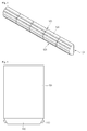
- Fig. 1 is a perspective view illustrating a backlight unit according to an embodiment.
- Fig. 2 is a sectional view taken along line A-A of Fig. 1 .
- Fig. 3 is a view illustrating an optical engine illustrated in Fig. 1 .
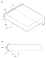
- Fig. 4 is a view illustrating a backlight unit according to another embodiment.
- Fig. 5 is a view illustrating a backlight unit according to another embodiment.
- Fig. 6 is a view illustrating a liquid crystal display according to an embodiment.
- Fig. 7 is a perspective view illustrating a backlight unit according to another embodiment.
- Fig. 8 is a sectional view taken along line B-B of Fig. 7 .
- Fig. 9 is a view illustrating a light guide plate illustrated in Fig. 7 .
- Fig. 10 is a view illustrating a backlight unit according to another embodiment.
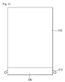
- Fig. 11 is a view illustrating a backlight unit according to another embodiment.
- Fig. 1 is a perspective view illustrating a backlight unit according to an embodiment
- Fig. 2 is a sectional view taken along line A-A of Fig. 1
- Fig. 3 is a view illustrating an optical engine illustrated in Fig. 1 .
- the backlight unit of the embodiment comprises a light emitting part 110, an optical engine 120, a light guide plate 130, and a reflector 140.
- the light emitting part 110 may comprise a light emitting device such as a light emitting diode. Alternatively, the light emitting part 110 may comprise a light emitting device package. The light emitting part 110 may comprise a red light emitting device, a green light emitting device, a blue light emitting device, and a white light emitting device. The light emitting part 110 may provide light to the optical engine 120.
- a light emitting device such as a light emitting diode.
- the light emitting part 110 may comprise a light emitting device package.
- the light emitting part 110 may comprise a red light emitting device, a green light emitting device, a blue light emitting device, and a white light emitting device.
- the light emitting part 110 may provide light to the optical engine 120.
- the light emitting part 110 may be disposed at a side or sides of the optical engine 120.
- the light emitting part 110 may be disposed at a side of the optical engine 120.
- the light emitting part 110 may be disposed at both sides of the optical engine 120.
- the reflector 140 may be disposed at the optical engine 120.
- the reflector 140 may be disposed at the rear and lateral sides of the optical engine 120.
- Light emitted from the light emitting part 110 may propagate throughout the inside of the optical engine 120.
- Light emitted from the light emitting part 110 disposed at a side of the optical engine 120 may propagate to the other side of the optical engine 120.
- light emitted from the light emitting part 110 may be reflected by the reflector 140 toward the other side of the optical engine 120.
- a first uneven part 121 is disposed on a surface of the optical engine 120.
- An uneven part corresponding to the first uneven part 121 is disposed on a surface of the light guide plate 130 facing the surface of the optical engine 120 where the first uneven part 121 is disposed. That is, the first uneven part 121 is disposed on the surface of the optical engine from which light is emitted to the light guide plate 130. Owing to the first uneven part 121, light propagating in the optical engine 120 can be efficiently extracted to the outside. Then, the light extracted from the optical engine 120 to the outside may be efficiently incident on the light guide plate 130. Light provided by the optical engine 120 may propagate in the light guide plate 130. Light propagating in the light guide plate 130 may be extracted through the upper side of the light guide plate 130.
- a second uneven part 123 is disposed on a surface of the optical engine 120 corresponding to the reflector 140.
- the second uneven part 123 may be formed along a first direction parallel to the longitudinal direction of the optical engine 120. That is to say, on the circumference of the optical engine 120, a plurality of paths can be defined as an intersection formed by the circumference of the optical engine 120 and arbitrary planes parallel to the longitudinal direction of the optical engine 120, and the second uneven part 125 may be formed along at least one of the plurality of paths formed as above.
- the second uneven part 123 light emitted from the light emitting part 110 may be efficiently dispersed in the optical engine 120.
- the reflector 140 is disposed. Thus, light incident on the second uneven part 123 may be reflected and efficiently dispersed in the optical engine 120.
- the reflector 140 may be formed of a metal such as silver (Ag), tungsten (W), and aluminum (Al), or another reflective material.
- the optical engine 120 may be formed of a resin.
- the reflector 140 may be disposed on the optical engine 120 by deposition or coating.
- the optical engine 120 may be formed of a material such as polyimide (PI) or polymethylmethacrylate (PMMA).
- the optical engine 120 may be formed of a silicon resin or an epoxy resin.
- a third uneven part 125 may be disposed on the optical engine 120.
- the third uneven part 125 may be formed along a second direction perpendicular to the longitudinal direction of the optical engine 120. That is to say, on the circumference of the optical engine 120, a plurality of paths can be defined as an intersection formed by the circumference of the optical engine 120 and arbitrary planes perpendicular to the longitudinal direction of the optical engine 120, and the third uneven part 125 may be formed along at least one of the plurality of paths formed as above. Owing to the second uneven part 123 and the third uneven part 125, light emitted from the light emitting part 110 may be reflected and dispersed.
- light emitted from the light emitting part 110 disposed at a side of the optical engine 120 can propagate to the other side of the optical engine 120.
- Light reflected by the second uneven part 123 and the third uneven part 125 may be incident on the light guide plate 130.
- light emitted from the light emitting part 110 disposed at a side of the optical engine 120 can propagate uniformly throughout the inside of the optical engine 120.
- the light uniformly propagating in the optical engine 120 may be uniformly supplied to the light guide plate 130. That is, according to the embodiment, although the light emitting part 110 is disposed at a side of the optical engine 120, light can be sufficiently supplied to the light guide plate 130. Therefore, according to the embodiment, fewer light emitting devices may be used in the backlight unit, and thus the backlight unit may be manufactured through simple processes with lower costs.
- the side of the optical engine 120 where the light emitting part 110 is disposed may be inclined.
- the incident angle of light emitted from the light emitting part 110 can be adjusted.
- the side of the optical engine 120 may be inclined in a manner such that some of light emitted from the light emitting part 110 can be toward the light guide plate 130. This structure is shown in Fig. 4 . In Fig. 4 , an optical engine 120 is not shown because it is hidden in a reflector 140.
- the light emitting part 110 may be disposed at a side of the optical engine 120 in an inclined position.
- the light emitting part 110 may be disposed at the side of the optical engine 120 in an inclined position. In this way, the incident angle of light emitted from the light emitting part 110 can be adjusted. If necessary, the angle of the light emitting part 110 may be adjusted so that some of light emitted from the light emitting part 110 can be toward the light guide plate 130.
- This structure is shown in Fig. 5 . In Fig. 5 , an optical engine 120 is not shown because it is hidden by a reflector 140.
- the first to third uneven parts 121, 123, and 125 may have a groove shape.
- the groove shape may be varied.
- the first to third uneven parts 121, 123, and 125 may have a protrusion shape.
- the first to third uneven parts 121, 123, and 125 may have a regular or random pattern shape. According to the characteristics of an optical system, the shapes of the first to third uneven parts 121, 123, and 125 may be varied for optimization.
- the light emitting part 110 may be disposed at a side of the optical engine 120.
- the light emitting part 110 may be disposed in contact with a side of the outside of the optical engine 120.
- the light emitting part 110 may be disposed at a side of the inside of the optical engine 120.
- a backlight unit 605 is disposed under a liquid crystal panel 601 to constitute a display device.
- the liquid crystal panel 601 may display images by using light emitted from the backlight unit 605.
- An optical sheet 603 may be disposed between the backlight unit 605 and the liquid crystal panel 601.
- the optical sheet 603 may comprise one or more sheets.
- the optical sheet 603 may comprise a diffusion sheet and a prism sheet.
- a reflection plate 607 may be disposed under the backlight unit 605.
- the reflection plate 607 is disposed under the backlight unit 605 so that light emitted from the backlight unit 605 can be reflected upward.
- Fig. 7 is a perspective view illustrating a backlight unit according to another embodiment
- Fig. 8 is a sectional view taken along line B-B of Fig. 7
- Fig. 9 is a view illustrating a light guide plate illustrated in Fig. 7 .
- the backlight unit of the embodiment comprises a light emitting part 410, a light guide plate 430, and a reflector 440.
- the light emitting part 410 may comprise a light emitting device such as a light emitting diode.
- the light emitting part 410 may comprise a red light emitting device, a green light emitting device, a blue light emitting device, and a white light emitting device.
- the light emitting part 410 may provide light to the light guide plate 430.
- the light guide plate 430 may comprise an optical engine 431 and an optical propagation part 433. Light provided from the light emitting part 410 may propagate through the optical engine 431. In addition, light provided from the optical engine 431 may propagate through the optical propagation part 433.
- the optical engine 431 and the optical propagation part 433 may be provided in one piece. That is, the optical engine 431 and the optical propagation part 433 may be integrated and provided as one body.
- the light emitting part 410 may be disposed at a side or sides of the optical engine 431.
- the light emitting part 410 may be disposed at a side of the optical engine 431.
- the light emitting part 410 may be disposed at both sides of the optical engine 431.
- the reflector 440 may be disposed at the optical engine 431.
- the reflector 440 may be disposed at the rear and lateral sides of the optical engine 431. Light emitted from the light emitting part 410 may propagate throughout the inside of the optical engine 431. Light emitted from the light emitting part 410 disposed at a side of the optical engine 431 may propagate to the other side of the optical engine 431.
- light emitted from the light emitting part 410 may be reflected by the reflector 440 toward the other side of the optical engine 431.
- Light provided from the optical engine 431 may propagate throughout the inside of the optical propagation part 433.
- Light propagating in the optical propagation part 433 may be extracted upward.
- a first uneven part 435 is disposed at a surface of the optical engine 431 corresponding to the reflector 440. Owing to the first uneven part 435, light provided form the light emitting part 410 can propagate and disperse efficiently in the optical engine 431.
- the reflector 440 is disposed at the backside of the first uneven part 435. Thus, light incident on the first uneven part 435 can be reflected and dispersed efficiently in the optical engine 431.
- the reflector 440 may be formed of a metal such as silver (Ag), tungsten (W), and aluminum (Al), or another reflective material.
- the optical engine 431 may be formed of a resin.
- the reflector 440 may be disposed on the optical engine 431 by deposition or coating.
- the optical engine 431 may be formed of a material such as polyimide (PI) or polymethylmethacrylate (PMMA).
- a second uneven part 437 may be disposed at the optical engine 431. Owing to the first uneven part 435 and the second uneven part 437, light provided from the light emitting part 410 can be reflected and dispersed. Thus, light emitted from the light emitting part 410 disposed at a side of the optical engine 431 may propagate to the other side of the optical engine 431. In addition, light reflected by the first uneven part 435 and the second uneven part 437 may be incident on the light guide plate 430 efficiently.
- light emitted from the light emitting part 410 disposed at a side of the optical engine 431 can propagate uniformly throughout the inside of the optical engine 431.
- the light uniformly propagating in the optical engine 431 may be uniformly supplied to the light guide plate 430. That is, according to the embodiment, although the light emitting part 410 is disposed at a side of the optical engine 431, light can be sufficiently supplied to the light guide plate 430. Therefore, according to the embodiment, fewer light emitting devices may be used in the backlight unit, and thus the backlight unit may be manufactured through simple processes with lower costs.
- the side of the optical engine 431 where the light emitting part 410 is disposed may be inclined.
- the incident angle of light emitted from the light emitting part 410 can be adjusted.
- the side of the optical engine 431 may be inclined in a manner such that some of light emitted from the light emitting part 410 can be toward the optical propagation part 433. This structure is shown in Fig. 10 .
- an optical engine 431 is not shown because it is hidden in a reflector 440.
- the light emitting part 410 may be disposed at a side of the optical engine 431 in an inclined position.
- the light emitting part 410 may be disposed at the side of the optical engine 120 in an inclined position. In this way, the incident angle of light emitted from the light emitting part 410 can be adjusted. If necessary, the angle of the light emitting part 410 may be adjusted so that some of light emitted from the light emitting part 410 can be toward the optical propagation part 433.
- This structure is shown in Fig. 11 . In Fig. 11 , an optical engine 431 is not shown because it is hidden by a reflector 440.
- the first and second uneven parts 435 and 437 may have a groove shape.
- the groove shape may be varied.
- the first and second uneven parts 435 and 437 may have a protrusion shape.
- the first and second uneven parts 435 and 437 may have a regular or random pattern shape. According to the characteristics of an optical system, the shapes of the first and second uneven parts 435 and 437 may be varied for optimization.
- the light emitting part 410 may be disposed at a side of the optical engine 431.
- the light emitting part 410 may be disposed in contact with a side of the outside of the optical engine 431.
- the light emitting part 410 may be disposed at a side of the inside of the optical engine 431.
- the above-described backlight unit can be applied to a display device such as a liquid crystal display. That is, the backlight unit of the embodiment may be disposed under a liquid crystal panel to constitute a display device.
- the liquid crystal panel may display images by using light emitted from the backlight unit.
- An optical sheet may be disposed between the backlight unit and the liquid crystal panel.
- the optical sheet may comprise one or more sheets.
- the optical sheet may comprise a diffusion sheet and a prism sheet.
- a reflection plate may be disposed under the backlight unit. The reflection plate is disposed under the backlight unit so that light emitted from the backlight unit can be reflected upward.
- the embodiments provide a backlight unit that can provide light efficiently and be made with lower costs, and a display device including the backlight unit.
- the embodiments can be applied to light emitting devices for providing light efficiently.
Landscapes
- Physics & Mathematics (AREA)
- General Physics & Mathematics (AREA)
- Optics & Photonics (AREA)
- Planar Illumination Modules (AREA)
- Illuminated Signs And Luminous Advertising (AREA)
- Liquid Crystal (AREA)
Abstract
A backlight unit is provided. The backlight unit comprises a light emitting part configured to emit light; an optical engine in which light provided from the light emitting part propagates; and a light guide plate in which light provided from the optical engine propagates, wherein uneven parts are disposed on a surface of the optical engine from which light is emitted.
Description
- The present disclosure relates to a backlight unit and a display device including the backlight unit.
- A liquid crystal display may comprise a liquid crystal panel configured to display images, and a backlight unit disposed under the liquid crystal panel to provide light to the liquid crystal panel. The backlight unit may comprise a lamp or a light emitting diode (LED) as a light source.
- In the market, display devices such as liquid crystal displays are required to be much slimmer to satisfy customer's demands. For making slimmer back light unit, the Edge-LED lighting method can be used. In the Edge-LED lighting method, a plurality of LEDs are disposed not behind the entire LCD panel, but along the edges of the back light unit, which makes the LED TV thin.
- Meanwhile, since the price of LED is still high, manufacturing cost reduction and efficient use of light are required.
- Embodiments provide a backlight unit that can provide light efficiently and be made with lower costs, and a display device including the backlight unit.
- In an aspect of the present invention, a backlight unit is provided comprising: a light emitting part configured to emit light; an optical engine in which light provided from the light emitting part propagates; and a light guide plate in which light provided from the optical engine propagates, wherein uneven parts are disposed on a surface of the optical engine from which light is emitted. The light emitting part may comprise a light emitting device. Due to the uneven parts, the light is dispersed across the back light unit and the efficient of the light can be improved.
- In another aspect of the present invention, the light emitting part is disposed at a side of the optical engine. Since the light emitting part is disposed at a side of the optical engine and the optical engine comprises uneven parts, less number of LEDs can be used in the production to achieve similar level of light. Therefore, the backlight unit may be manufactured through simple processes with lower costs.
- In another aspect of the present invention, the side of the optical engine at which the light emitting part is disposed is inclined. Furthermore, the light emitting part may be disposed at the side of the optical engine in an inclined position. In this way, the incident angle of light emitted from the light emitting part can be adjusted.
- In another aspect of the present invention, an uneven part among the uneven parts is disposed on a surface of the light guide plate corresponding to the surface of the optical engine from which light is emitted. This helps the light scattered uniformly through the light guide plate.
- In another aspect of the present invention, the backlight unit further comprises a reflector disposed at a surface of the optical engine. The the backlight unit may further comprise an uneven part among the uneven parts being disposed at the optical engine in a region corresponding to the reflector.
- In another aspect of the present invention, the uneven part disposed at the optical engine in the region corresponding to the reflector is formed of groove shape, protrusion shape, regular pattern shape, or random pattern shape.
- The uneven pattern may have a direction. For example, when the unevent part is formed of groove shape or protrusion shape, etc, the groove or protrusion may have a linear shape, and the direction of it can be defined.
- In this situation, the uneven part disposed at the optical engine in the region corresponding to the reflector may be formed along a first direction parallel to the longitudinal direction of the optical engine. Alternatively, the uneven part disposed at the optical engine in the region corresponding to the reflector may be formed along a second direction perpendicular to the longitudinal direction of the optical engine. Otherwise, the optical engine may have a plurality of uneven parts whose direction are different each other.
- In another aspect of the present invention, the optical engine is formed of a material selected at least one from the group consisting of polyimide (PI), polymethylmethacrylate (PMMA), a silicon resin, and an epoxy resin.
- In another aspect of the present invention, a display device is provided comprising: a backlight unit; and a liquid crystal panel configured to receive light from the backlight unit, wherein the backlight unit comprising: a light emitting part configured to emit light; an optical engine in which light provided from the light emitting part propagates; and a light guide plate in which light provided from the optical engine propagates, wherein uneven parts are disposed on a surface of the optical engine from which light is emitted.
- The details of one or more embodiments are set forth in the accompanying drawings and the description below. Other features will be apparent from the description and drawings, and from the claims.
-
Fig. 1 is a perspective view illustrating a backlight unit according to an embodiment. -
Fig. 2 is a sectional view taken along line A-A ofFig. 1 . -
Fig. 3 is a view illustrating an optical engine illustrated inFig. 1 . -
Fig. 4 is a view illustrating a backlight unit according to another embodiment. -
Fig. 5 is a view illustrating a backlight unit according to another embodiment. -
Fig. 6 is a view illustrating a liquid crystal display according to an embodiment. -
Fig. 7 is a perspective view illustrating a backlight unit according to another embodiment. -
Fig. 8 is a sectional view taken along line B-B ofFig. 7 . -
Fig. 9 is a view illustrating a light guide plate illustrated inFig. 7 . -
Fig. 10 is a view illustrating a backlight unit according to another embodiment. -
Fig. 11 is a view illustrating a backlight unit according to another embodiment. - In the following description, it will be understood that when a part such as a layer (film), a region, a pattern, a structure, and a substrate is referred to as being 'on' another part, it can be directly on the another part, or intervening parts may also be present. Further, it will be understood that when a part is referred to as being 'under' another part, it can be directly under the other part, and one or more intervening parts may also be present. In addition, it will also be understood that when a part is referred to as being 'between' two parts, it can be the only part between the two parts, or one or more intervening parts may also be present. Spatially relative terms, such as "upper" and "lower" are used herein for ease of description to describe one element or feature's relationship to another element(s) or feature(s) as illustrated in the figures.
- In the drawings, the thicknesses or sizes of layers are exaggerated, omitted, or schematically shown for brevity of description and clarity. In addition, the sizes of elements shown in the drawings may be different from their real sizes.
- Embodiments will now be described with reference to the accompanying drawings.
-
Fig. 1 is a perspective view illustrating a backlight unit according to an embodiment,Fig. 2 is a sectional view taken along line A-A ofFig. 1 , andFig. 3 is a view illustrating an optical engine illustrated inFig. 1 . - The backlight unit of the embodiment comprises a
light emitting part 110, anoptical engine 120, alight guide plate 130, and areflector 140. - The
light emitting part 110 may comprise a light emitting device such as a light emitting diode. Alternatively, thelight emitting part 110 may comprise a light emitting device package. Thelight emitting part 110 may comprise a red light emitting device, a green light emitting device, a blue light emitting device, and a white light emitting device. Thelight emitting part 110 may provide light to theoptical engine 120. - The
light emitting part 110 may be disposed at a side or sides of theoptical engine 120. For example, thelight emitting part 110 may be disposed at a side of theoptical engine 120. In another example, thelight emitting part 110 may be disposed at both sides of theoptical engine 120. Thereflector 140 may be disposed at theoptical engine 120. Thereflector 140 may be disposed at the rear and lateral sides of theoptical engine 120. Light emitted from thelight emitting part 110 may propagate throughout the inside of theoptical engine 120. Light emitted from thelight emitting part 110 disposed at a side of theoptical engine 120 may propagate to the other side of theoptical engine 120. In addition, light emitted from thelight emitting part 110 may be reflected by thereflector 140 toward the other side of theoptical engine 120. - A first
uneven part 121 is disposed on a surface of theoptical engine 120. An uneven part corresponding to the firstuneven part 121 is disposed on a surface of thelight guide plate 130 facing the surface of theoptical engine 120 where the firstuneven part 121 is disposed. That is, the firstuneven part 121 is disposed on the surface of the optical engine from which light is emitted to thelight guide plate 130. Owing to the firstuneven part 121, light propagating in theoptical engine 120 can be efficiently extracted to the outside. Then, the light extracted from theoptical engine 120 to the outside may be efficiently incident on thelight guide plate 130. Light provided by theoptical engine 120 may propagate in thelight guide plate 130. Light propagating in thelight guide plate 130 may be extracted through the upper side of thelight guide plate 130. - A second
uneven part 123 is disposed on a surface of theoptical engine 120 corresponding to thereflector 140. The seconduneven part 123 may be formed along a first direction parallel to the longitudinal direction of theoptical engine 120. That is to say, on the circumference of theoptical engine 120, a plurality of paths can be defined as an intersection formed by the circumference of theoptical engine 120 and arbitrary planes parallel to the longitudinal direction of theoptical engine 120, and the seconduneven part 125 may be formed along at least one of the plurality of paths formed as above. Owing to the seconduneven part 123, light emitted from thelight emitting part 110 may be efficiently dispersed in theoptical engine 120. At a backside of the seconduneven part 123, thereflector 140 is disposed. Thus, light incident on the seconduneven part 123 may be reflected and efficiently dispersed in theoptical engine 120. - The
reflector 140 may be formed of a metal such as silver (Ag), tungsten (W), and aluminum (Al), or another reflective material. Theoptical engine 120 may be formed of a resin. Thereflector 140 may be disposed on theoptical engine 120 by deposition or coating. For example, theoptical engine 120 may be formed of a material such as polyimide (PI) or polymethylmethacrylate (PMMA). Alternatively, theoptical engine 120 may be formed of a silicon resin or an epoxy resin. - A third
uneven part 125 may be disposed on theoptical engine 120. The thirduneven part 125 may be formed along a second direction perpendicular to the longitudinal direction of theoptical engine 120. That is to say, on the circumference of theoptical engine 120, a plurality of paths can be defined as an intersection formed by the circumference of theoptical engine 120 and arbitrary planes perpendicular to the longitudinal direction of theoptical engine 120, and the thirduneven part 125 may be formed along at least one of the plurality of paths formed as above. Owing to the seconduneven part 123 and the thirduneven part 125, light emitted from thelight emitting part 110 may be reflected and dispersed. In this way, light emitted from thelight emitting part 110 disposed at a side of theoptical engine 120 can propagate to the other side of theoptical engine 120. Light reflected by the seconduneven part 123 and the thirduneven part 125 may be incident on thelight guide plate 130. - According to the embodiment, light emitted from the
light emitting part 110 disposed at a side of theoptical engine 120 can propagate uniformly throughout the inside of theoptical engine 120. In addition, the light uniformly propagating in theoptical engine 120 may be uniformly supplied to thelight guide plate 130. That is, according to the embodiment, although thelight emitting part 110 is disposed at a side of theoptical engine 120, light can be sufficiently supplied to thelight guide plate 130. Therefore, according to the embodiment, fewer light emitting devices may be used in the backlight unit, and thus the backlight unit may be manufactured through simple processes with lower costs. - Alternatively, the side of the
optical engine 120 where thelight emitting part 110 is disposed may be inclined. By this structural change, the incident angle of light emitted from thelight emitting part 110 can be adjusted. If necessary, the side of theoptical engine 120 may be inclined in a manner such that some of light emitted from thelight emitting part 110 can be toward thelight guide plate 130. This structure is shown inFig. 4 . InFig. 4 , anoptical engine 120 is not shown because it is hidden in areflector 140. - The
light emitting part 110 may be disposed at a side of theoptical engine 120 in an inclined position. For example, instead of inclining a side of theoptical engine 120, thelight emitting part 110 may be disposed at the side of theoptical engine 120 in an inclined position. In this way, the incident angle of light emitted from thelight emitting part 110 can be adjusted. If necessary, the angle of thelight emitting part 110 may be adjusted so that some of light emitted from thelight emitting part 110 can be toward thelight guide plate 130. This structure is shown inFig. 5 . InFig. 5 , anoptical engine 120 is not shown because it is hidden by areflector 140. - The first to third
uneven parts uneven parts uneven parts uneven parts - The
light emitting part 110 may be disposed at a side of theoptical engine 120. For example, thelight emitting part 110 may be disposed in contact with a side of the outside of theoptical engine 120. In another example, thelight emitting part 110 may be disposed at a side of the inside of theoptical engine 120. - The above-described backlight unit can be applied to a display device such as a liquid crystal display. In an embodiment shown in
Fig. 6 , abacklight unit 605 is disposed under aliquid crystal panel 601 to constitute a display device. Theliquid crystal panel 601 may display images by using light emitted from thebacklight unit 605. Anoptical sheet 603 may be disposed between thebacklight unit 605 and theliquid crystal panel 601. Theoptical sheet 603 may comprise one or more sheets. Theoptical sheet 603 may comprise a diffusion sheet and a prism sheet. Areflection plate 607 may be disposed under thebacklight unit 605. Thereflection plate 607 is disposed under thebacklight unit 605 so that light emitted from thebacklight unit 605 can be reflected upward. -
Fig. 7 is a perspective view illustrating a backlight unit according to another embodiment,Fig. 8 is a sectional view taken along line B-B ofFig. 7 , andFig. 9 is a view illustrating a light guide plate illustrated inFig. 7 . - The backlight unit of the embodiment comprises a
light emitting part 410, alight guide plate 430, and areflector 440. - The
light emitting part 410 may comprise a light emitting device such as a light emitting diode. Thelight emitting part 410 may comprise a red light emitting device, a green light emitting device, a blue light emitting device, and a white light emitting device. Thelight emitting part 410 may provide light to thelight guide plate 430. - The
light guide plate 430 may comprise anoptical engine 431 and anoptical propagation part 433. Light provided from thelight emitting part 410 may propagate through theoptical engine 431. In addition, light provided from theoptical engine 431 may propagate through theoptical propagation part 433. Theoptical engine 431 and theoptical propagation part 433 may be provided in one piece. That is, theoptical engine 431 and theoptical propagation part 433 may be integrated and provided as one body. - The
light emitting part 410 may be disposed at a side or sides of theoptical engine 431. For example, thelight emitting part 410 may be disposed at a side of theoptical engine 431. In another example, thelight emitting part 410 may be disposed at both sides of theoptical engine 431. Thereflector 440 may be disposed at theoptical engine 431. Thereflector 440 may be disposed at the rear and lateral sides of theoptical engine 431. Light emitted from thelight emitting part 410 may propagate throughout the inside of theoptical engine 431. Light emitted from thelight emitting part 410 disposed at a side of theoptical engine 431 may propagate to the other side of theoptical engine 431. In addition, light emitted from thelight emitting part 410 may be reflected by thereflector 440 toward the other side of theoptical engine 431. Light provided from theoptical engine 431 may propagate throughout the inside of theoptical propagation part 433. Light propagating in theoptical propagation part 433 may be extracted upward. - A first
uneven part 435 is disposed at a surface of theoptical engine 431 corresponding to thereflector 440. Owing to the firstuneven part 435, light provided form thelight emitting part 410 can propagate and disperse efficiently in theoptical engine 431. Thereflector 440 is disposed at the backside of the firstuneven part 435. Thus, light incident on the firstuneven part 435 can be reflected and dispersed efficiently in theoptical engine 431. - The
reflector 440 may be formed of a metal such as silver (Ag), tungsten (W), and aluminum (Al), or another reflective material. Theoptical engine 431 may be formed of a resin. Thereflector 440 may be disposed on theoptical engine 431 by deposition or coating. For example, theoptical engine 431 may be formed of a material such as polyimide (PI) or polymethylmethacrylate (PMMA). - A second
uneven part 437 may be disposed at theoptical engine 431. Owing to the firstuneven part 435 and the seconduneven part 437, light provided from thelight emitting part 410 can be reflected and dispersed. Thus, light emitted from thelight emitting part 410 disposed at a side of theoptical engine 431 may propagate to the other side of theoptical engine 431. In addition, light reflected by the firstuneven part 435 and the seconduneven part 437 may be incident on thelight guide plate 430 efficiently. - According to the embodiment, light emitted from the
light emitting part 410 disposed at a side of theoptical engine 431 can propagate uniformly throughout the inside of theoptical engine 431. In addition, the light uniformly propagating in theoptical engine 431 may be uniformly supplied to thelight guide plate 430. That is, according to the embodiment, although thelight emitting part 410 is disposed at a side of theoptical engine 431, light can be sufficiently supplied to thelight guide plate 430. Therefore, according to the embodiment, fewer light emitting devices may be used in the backlight unit, and thus the backlight unit may be manufactured through simple processes with lower costs. - Alternatively, the side of the
optical engine 431 where thelight emitting part 410 is disposed may be inclined. By this structural change, the incident angle of light emitted from thelight emitting part 410 can be adjusted. If necessary, the side of theoptical engine 431 may be inclined in a manner such that some of light emitted from thelight emitting part 410 can be toward theoptical propagation part 433. This structure is shown inFig. 10 . InFig. 10 , anoptical engine 431 is not shown because it is hidden in areflector 440. - The
light emitting part 410 may be disposed at a side of theoptical engine 431 in an inclined position. For example, instead of inclining a side of theoptical engine 431, thelight emitting part 410 may be disposed at the side of theoptical engine 120 in an inclined position. In this way, the incident angle of light emitted from thelight emitting part 410 can be adjusted. If necessary, the angle of thelight emitting part 410 may be adjusted so that some of light emitted from thelight emitting part 410 can be toward theoptical propagation part 433. This structure is shown inFig. 11 . InFig. 11 , anoptical engine 431 is not shown because it is hidden by areflector 440. - The first and second
uneven parts uneven parts uneven parts uneven parts - The
light emitting part 410 may be disposed at a side of theoptical engine 431. For example, thelight emitting part 410 may be disposed in contact with a side of the outside of theoptical engine 431. In another example, thelight emitting part 410 may be disposed at a side of the inside of theoptical engine 431. - The above-described backlight unit can be applied to a display device such as a liquid crystal display. That is, the backlight unit of the embodiment may be disposed under a liquid crystal panel to constitute a display device. The liquid crystal panel may display images by using light emitted from the backlight unit. An optical sheet may be disposed between the backlight unit and the liquid crystal panel. The optical sheet may comprise one or more sheets. The optical sheet may comprise a diffusion sheet and a prism sheet. A reflection plate may be disposed under the backlight unit. The reflection plate is disposed under the backlight unit so that light emitted from the backlight unit can be reflected upward.
- As described above, the embodiments provide a backlight unit that can provide light efficiently and be made with lower costs, and a display device including the backlight unit.
- In addition, the embodiments can be applied to light emitting devices for providing light efficiently.
- Although embodiments have been described with reference to a number of illustrative embodiments thereof, it should be understood that numerous other modifications and embodiments can be devised by those skilled in the art that will fall within the spirit and scope of the principles of this disclosure. More particularly, various variations and modifications are possible in the component parts and/or arrangements of the subject combination arrangement within the scope of the disclosure and the drawings. In addition to variations and modifications in the component parts and/or arrangements, alternative uses will also be apparent to those skilled in the art.
Claims (15)
- A backlight unit comprising:a light emitting part (110) configured to emit light;an optical engine (120) in which light provided from the light emitting part (110) propagates; anda light guide plate (130) in which light provided from the optical engine (120) propagates,wherein uneven parts (121, 123, 125) are disposed on a surface of the optical engine (120) from which light is emitted.
- The backlight unit according to claim 1, wherein the light emitting part (110) comprises a light emitting device.
- The backlight unit according to claim 1, wherein the light emitting part (110) is disposed at a side of the optical engine (120).
- The backlight unit according to claim 3, wherein the side of the optical engine (120) at which the light emitting part (110) is disposed is inclined.
- The backlight unit according to claim 3, wherein the light emitting part (110) is disposed at the side of the optical engine (120) in an inclined position.
- The backlight unit according to claim 1, wherein an uneven part (121) among the uneven parts (121, 123, 125) is disposed on a surface of the light guide plate (130) corresponding to the surface of the optical engine (120) from which light is emitted.
- The backlight unit according to claim 1, further comprising a reflector (140) disposed at a surface of the optical engine (120).
- The backlight unit according to claim 7, further comprising an uneven part (123, 125) among the uneven parts (121, 123, 125) being disposed at the optical engine (120) in a region corresponding to the reflector (140).
- The backlight unit according to claim 8, wherein the uneven part (123) disposed at the optical engine in the region corresponding to the reflector is formed along a first direction parallel to the longitudinal direction of the optical engine (120).
- The backlight unit according to claim 8, wherein the uneven part (125) disposed at the optical engine in the region corresponding to the reflector is formed along a second direction perpendicular to the longitudinal direction of the optical engine.
- The backlight unit according to claim 8, wherein the uneven part disposed at the optical engine (120) in the region corresponding to the reflector (140) is formed of groove shape, protrusion shape, regular pattern shape, or random pattern shape.
- The backlight unit according to claim 1, wherein the optical engine (120) is formed of a material selected at least one from the group consisting of polyimide (PI), polymethylmethacrylate (PMMA), a silicon resin, and an epoxy resin.
- A display device comprising:the backlight unit (605) of any one of claims 1 to 12; anda liquid crystal panel (601) configured to receive light from the backlight unit (605).
- The display device according to claim 13, further comprising an optical sheet (603) between the backlight unit (605) and the liquid crystal panel (601).
- The display device according to claim 13, further comprising a reflection plate (607) under the backlight unit (605).
Applications Claiming Priority (1)
| Application Number | Priority Date | Filing Date | Title |
|---|---|---|---|
| KR20100004117 | 2010-01-15 |
Publications (1)
| Publication Number | Publication Date |
|---|---|
| EP2360501A1 true EP2360501A1 (en) | 2011-08-24 |
Family
ID=43877281
Family Applications (1)
| Application Number | Title | Priority Date | Filing Date |
|---|---|---|---|
| EP11150925A Withdrawn EP2360501A1 (en) | 2010-01-15 | 2011-01-14 | Backlight unit and display device having the same |
Country Status (4)
| Country | Link |
|---|---|
| US (1) | US20110176085A1 (en) |
| EP (1) | EP2360501A1 (en) |
| JP (1) | JP2011146381A (en) |
| CN (1) | CN102128390A (en) |
Families Citing this family (1)
| Publication number | Priority date | Publication date | Assignee | Title |
|---|---|---|---|---|
| JP2013035453A (en) * | 2011-08-09 | 2013-02-21 | Tamura Plastic Mfg Co Ltd | Automobile exterior part, and automobile visor |
Citations (3)
| Publication number | Priority date | Publication date | Assignee | Title |
|---|---|---|---|---|
| US20010035927A1 (en) * | 2000-03-31 | 2001-11-01 | Tomohiro Sasagawa | Front light, reflective liquid crystal display device and personal digital assistant |
| US20030117792A1 (en) * | 2001-12-25 | 2003-06-26 | Minebea Co. Ltd. | Spread illuminating apparatus with means for reflecting light dispersely |
| US20070177070A1 (en) * | 2006-01-27 | 2007-08-02 | Au Optronics Corp. | Light emitting device |
Family Cites Families (9)
| Publication number | Priority date | Publication date | Assignee | Title |
|---|---|---|---|---|
| JP4006918B2 (en) * | 2000-02-28 | 2007-11-14 | オムロン株式会社 | Surface light source device and manufacturing method thereof |
| KR100783619B1 (en) * | 2002-06-29 | 2007-12-07 | 삼성전자주식회사 | Lighting device and backlight assembly and liquid crystal display device having the same |
| CN2627535Y (en) * | 2003-05-14 | 2004-07-21 | 统宝光电股份有限公司 | Structure of illuminator |
| CN100376979C (en) * | 2003-11-01 | 2008-03-26 | 鸿富锦精密工业(深圳)有限公司 | Backlight module |
| US20060103777A1 (en) * | 2004-11-15 | 2006-05-18 | 3M Innovative Properties Company | Optical film having a structured surface with rectangular based prisms |
| CN100445827C (en) * | 2004-11-18 | 2008-12-24 | 清华大学 | Light guide plate and backlight module |
| CN100443995C (en) * | 2006-02-10 | 2008-12-17 | 友达光电股份有限公司 | Multi-light source backlight module |
| KR101263502B1 (en) * | 2006-03-27 | 2013-05-13 | 엘지디스플레이 주식회사 | Light Emitting Diode Back Light Unit and Liquid Crystal Display Device having thereof |
| JP4585481B2 (en) * | 2006-04-28 | 2010-11-24 | 株式会社 日立ディスプレイズ | LED backlight and liquid crystal display device using the same |
-
2011
- 2011-01-12 JP JP2011004092A patent/JP2011146381A/en not_active Withdrawn
- 2011-01-14 EP EP11150925A patent/EP2360501A1/en not_active Withdrawn
- 2011-01-14 CN CN2011100218046A patent/CN102128390A/en active Pending
- 2011-01-14 US US13/006,961 patent/US20110176085A1/en not_active Abandoned
Patent Citations (3)
| Publication number | Priority date | Publication date | Assignee | Title |
|---|---|---|---|---|
| US20010035927A1 (en) * | 2000-03-31 | 2001-11-01 | Tomohiro Sasagawa | Front light, reflective liquid crystal display device and personal digital assistant |
| US20030117792A1 (en) * | 2001-12-25 | 2003-06-26 | Minebea Co. Ltd. | Spread illuminating apparatus with means for reflecting light dispersely |
| US20070177070A1 (en) * | 2006-01-27 | 2007-08-02 | Au Optronics Corp. | Light emitting device |
Also Published As
| Publication number | Publication date |
|---|---|
| CN102128390A (en) | 2011-07-20 |
| US20110176085A1 (en) | 2011-07-21 |
| JP2011146381A (en) | 2011-07-28 |
Similar Documents
| Publication | Publication Date | Title |
|---|---|---|
| CN101542191B (en) | Backlight and display | |
| CN103777382B (en) | It is bent display device | |
| US10295825B2 (en) | Projection system for display, in particular a heads-up display, and associated display | |
| KR101571919B1 (en) | Collimating light engine | |
| US7195364B2 (en) | Backlight apparatus reduced in thickness | |
| JP5116712B2 (en) | Liquid crystal display | |
| US7186013B2 (en) | Large size backlight apparatus reduced in thickness | |
| US9477117B2 (en) | Optical lens module and backlight unit | |
| EP2388513B1 (en) | Light module | |
| KR20200037870A (en) | Light guide with grating | |
| CN108700263A (en) | Lighting device and display device | |
| CN104180241A (en) | Backlight module | |
| KR20160051292A (en) | lens,light emitting apparatus including the lens, and backlight unit including the apparatus | |
| JP5470506B1 (en) | Planar illumination device and display device having planar illumination device | |
| JP2012243653A (en) | Backlight device and display device | |
| CN105527672A (en) | Area light source device, display device and electronic device | |
| CN102042558B (en) | Color mixing lens and liquid crystal display having the same | |
| WO2018199011A1 (en) | Backlight | |
| US10018778B2 (en) | Liquid crystal display device | |
| JP2005135815A (en) | Surface light source device and display device using the surface light source device | |
| US10281635B2 (en) | Light guide plate, backlight module and display device | |
| US20110176085A1 (en) | Backlight unit and display device having the same | |
| KR101586378B1 (en) | Backlight Unit | |
| TWI566013B (en) | Direct type backlight module and liquid crystal display device using same | |
| TWI390303B (en) | Backlight module and electronic device |
Legal Events
| Date | Code | Title | Description |
|---|---|---|---|
| PUAI | Public reference made under article 153(3) epc to a published international application that has entered the european phase |
Free format text: ORIGINAL CODE: 0009012 |
|
| AK | Designated contracting states |
Kind code of ref document: A1 Designated state(s): AL AT BE BG CH CY CZ DE DK EE ES FI FR GB GR HR HU IE IS IT LI LT LU LV MC MK MT NL NO PL PT RO RS SE SI SK SM TR |
|
| AX | Request for extension of the european patent |
Extension state: BA ME |
|
| 17P | Request for examination filed |
Effective date: 20120220 |
|
| 17Q | First examination report despatched |
Effective date: 20150120 |
|
| STAA | Information on the status of an ep patent application or granted ep patent |
Free format text: STATUS: THE APPLICATION IS DEEMED TO BE WITHDRAWN |
|
| 18D | Application deemed to be withdrawn |
Effective date: 20150501 |