EP2360395A1 - Ball screw - Google Patents
Ball screw Download PDFInfo
- Publication number
- EP2360395A1 EP2360395A1 EP10808963A EP10808963A EP2360395A1 EP 2360395 A1 EP2360395 A1 EP 2360395A1 EP 10808963 A EP10808963 A EP 10808963A EP 10808963 A EP10808963 A EP 10808963A EP 2360395 A1 EP2360395 A1 EP 2360395A1
- Authority
- EP
- European Patent Office
- Prior art keywords
- ball
- deflector
- screw
- nut
- scooping
- Prior art date
- Legal status (The legal status is an assumption and is not a legal conclusion. Google has not performed a legal analysis and makes no representation as to the accuracy of the status listed.)
- Withdrawn
Links
- 238000005096 rolling process Methods 0.000 claims abstract description 52
- 230000002093 peripheral effect Effects 0.000 claims abstract description 26
- 239000000463 material Substances 0.000 claims abstract description 9
- 239000011347 resin Substances 0.000 claims abstract description 6
- 229920005989 resin Polymers 0.000 claims abstract description 6
- 238000003780 insertion Methods 0.000 abstract description 4
- 230000037431 insertion Effects 0.000 abstract description 4
- 239000002184 metal Substances 0.000 description 7
- 238000005452 bending Methods 0.000 description 6
- 229910000831 Steel Inorganic materials 0.000 description 4
- 239000010959 steel Substances 0.000 description 4
- 239000000919 ceramic Substances 0.000 description 3
- 230000007547 defect Effects 0.000 description 2
- 229930182556 Polyacetal Natural products 0.000 description 1
- 230000015572 biosynthetic process Effects 0.000 description 1
- 230000000694 effects Effects 0.000 description 1
- 229920006351 engineering plastic Polymers 0.000 description 1
- 238000003754 machining Methods 0.000 description 1
- 238000000034 method Methods 0.000 description 1
- 238000012986 modification Methods 0.000 description 1
- 230000004048 modification Effects 0.000 description 1
- 229920006122 polyamide resin Polymers 0.000 description 1
- 229920006324 polyoxymethylene Polymers 0.000 description 1
- 239000012779 reinforcing material Substances 0.000 description 1
- 238000007790 scraping Methods 0.000 description 1
- 238000010408 sweeping Methods 0.000 description 1
Images

Classifications
-
- F—MECHANICAL ENGINEERING; LIGHTING; HEATING; WEAPONS; BLASTING
- F16—ENGINEERING ELEMENTS AND UNITS; GENERAL MEASURES FOR PRODUCING AND MAINTAINING EFFECTIVE FUNCTIONING OF MACHINES OR INSTALLATIONS; THERMAL INSULATION IN GENERAL
- F16H—GEARING
- F16H25/00—Gearings comprising primarily only cams, cam-followers and screw-and-nut mechanisms
- F16H25/18—Gearings comprising primarily only cams, cam-followers and screw-and-nut mechanisms for conveying or interconverting oscillating or reciprocating motions
- F16H25/20—Screw mechanisms
- F16H25/22—Screw mechanisms with balls, rollers, or similar members between the co-operating parts; Elements essential to the use of such members
- F16H25/2204—Screw mechanisms with balls, rollers, or similar members between the co-operating parts; Elements essential to the use of such members with balls
- F16H25/2214—Screw mechanisms with balls, rollers, or similar members between the co-operating parts; Elements essential to the use of such members with balls with elements for guiding the circulating balls
-
- Y—GENERAL TAGGING OF NEW TECHNOLOGICAL DEVELOPMENTS; GENERAL TAGGING OF CROSS-SECTIONAL TECHNOLOGIES SPANNING OVER SEVERAL SECTIONS OF THE IPC; TECHNICAL SUBJECTS COVERED BY FORMER USPC CROSS-REFERENCE ART COLLECTIONS [XRACs] AND DIGESTS
- Y10—TECHNICAL SUBJECTS COVERED BY FORMER USPC
- Y10T—TECHNICAL SUBJECTS COVERED BY FORMER US CLASSIFICATION
- Y10T74/00—Machine element or mechanism
- Y10T74/19—Gearing
- Y10T74/19642—Directly cooperating gears
- Y10T74/19698—Spiral
- Y10T74/19702—Screw and nut
- Y10T74/19744—Rolling element engaging thread
- Y10T74/19749—Recirculating rolling elements
- Y10T74/19767—Return path geometry
- Y10T74/19772—Rolling element deflector
Definitions
- the present invention relates to a ball screw, in particular to a ball screw with a deflector.
- a scooping-up site of a ball in a tube of the tube recirculation-type ball screw is formed by machining a tip of the tube made of a thin-walled metal tube or thin plate metal in tongue shape.
- the scooping-up site entails a problem that the scooping-up site experiences the unsatisfactory strength due to continuous collision of the ball when featured such scooping-up site in a high-load capacity and high-speed ball screw where the a large ball is furnished and the ball collides against a tongue at a high-speed.
- a prior art devised for improving the scooping-up site includes a ball disclosed in Patent Document 1.
- the ball screw (nut assembly) 110 has a screw 114 on a peripheral face of which a groove 114 is spirally formed and a nut 118.
- the nut 118 has a spiral grove 120 formed on its peripheral surface correspondingly to the groove 114.
- a plurality of balls 122 are disposed in a transfer path configured by the groove 114 and the groove 120.
- the transfer path is also provided with a circular tube 126 for returning back a ball 122 from a starting point to an end point.
- the ball screw (nut assembly) 110 is provided with a deflector (ball turning device) 130 in place of a tongue (not shown) of the recirculation tube 126.
- the deflector 130 is composed of a body 132 formed by bending in saddle shape a rod (usually, steel material) having a substantially circular cross-section and a screwed shaft 134.
- a fixing bolt for the deflector is provided by one at the center of the deflector.
- the ball screw is in danger of generating vibrations in the deflector when the deflector scoops up a ball, which may loosen the fixing bolt.
- the scooping-up site of the deflector has a plane and therefore is not to be able to scoop up a ball along a screw line of the ball screw.
- the ball draws a discontinuous locus, which induces problems that the scooping-up site is not qualified for high-speed use.
- the problems include the generation of noise, an incidence of scratch on a surface of the ball due to collision against the scooping-up site, and gripping of small pieces resulted from scraping off of the tongue in the ball grooves etc.
- the present invention has made to solve the defects as such and an object thereof is to provide a ball screw preventing a fixing bolt of a deflector from being loosened. Further, another object of the present invention is to provide a ball screw capable of implementing smooth scooping up of a ball by the deflector for noise reduction and to endure high-speed working conditions.
- a ball screw comprises a screw shaft having a spiral ball groove formed on its outer peripheral surface; a nut having a spiral ball groove opposing the ball screw groove of the screw shaft on its inner peripheral surface; a number of balls rolling along a spiral ball rolling path formed by the ball groove of the nut and the ball groove of the screw shaft; and a recirculation component provided on the nut for guiding so that the number of balls recirculate along the ball rolling path, wherein the recirculation component is composed of a deflector scooping up the balls and a ball returning member returning back the scooped up balls to the ball rolling path, and the deflector is fixed to the nut by a plurality of fixing members.
- a ball screw comprises a screw shaft having a spiral ball groove formed on its outer peripheral surface; a nut having a spiral ball groove opposing the ball screw groove of the screw shaft on its inner peripheral surface; a number of balls rolling along a spiral ball rolling path formed by the ball groove of the nut and the ball groove of the screw shaft; and a recirculation component provided on the nut for guiding so that the number of balls recirculate along the ball rolling path, wherein the recirculation component is composed of a deflector scoping up the balls and a ball returning member returning back the scooped up balls to the ball rolling path, and the deflector has a shape of scooping up the ball in the ball rolling member along a screw line toward the ball returning member.
- a through hole of the nut opposing the ball scooping-up surface of the deflector has a concave curved surface shape of scooping up the ball in the ball rolling path along the screw line toward the ball returning member.
- the ball scooping-up surface of the deflector has a concave curved surface shape of scooping up the ball in the ball rolling path along the screw line toward the ball returning path.
- the deflector is formed of resin material.
- the invention enables providing a deflector-type ball screw which is free from the generation of vibrations in the deflector and wipes out loosing of the fixing bolt, owing to the plural fixing members of the deflector.
- the invention allows providing a deflector-type ball screw capable of smoothly scooping up the ball with the deflector for noise reduction and to withstand high-speed working conditions.
- a nut 2 is fitted to an outer periphery of a screw shaft 1.
- a spiral ball groove 1a is formed on an outer peripheral surface of the screw shaft 1
- a spiral boll screw groove 2a opposing the ball screw groove 1a of the screw shaft 1 is formed on an inner peripheral surface of the nut 2.
- the ball screw groove 1a of the screw shaft 1 and the ball screw groove 2a of the nut 2 opposing each other constitute a spiral ball rolling path 3.
- Through holes 4a and 4b are formed on a peripheral wall of the nut 2 and the through holes 4a and 4b are connected with a ball returning member 5.
- the ball returning member 5 is made by bending a metal tube in substantially U-shape arranged on an outer peripheral surface of the nut 2 and the both ends thereof are inserted into the through holes 4a and 4b.
- the deflector 9 is disposed on the inner peripheral face of the nut 2, with the both ends thereof joined together, at a position of the both ends of the ball returning path 5, and is fixed to the nut 2 with the bolt 11 that is a fixing member.
- the deflector 9 is formed by bending arcuately a metal rod whose cross-section is of a substantially elliptical form is bent.
- the balls 8 in the ball rolling path 3 are scooped up by the both ends of the deflector 9 and is guided to the ball returning member 5.
- the ball returning member 5 By the ball returning member 5 the balls 8 are returned back again to the ball rolling path 3.
- the deflector 9 and the ball returning member 5 constitute a recirculation component 17.
- the through holes 4a and 4b and the recirculation component 17 constitute a connection path 6 connecting a part and another part remote from each other of the ball rolling path 3 to communicate with itself.
- the ball rolling path 3 communicates with itself in an endless manner through the connecting path 6 and the ball rolling path communicating in the endless manner is a ball recirculation path 7.
- a large number of balls 8 made of materials such as steel and ceramic etc., are accommodated in the ball rolling path 3 so as to continuously align in the endless manner therein.
- These balls 8 are endlessly recirculate in the ball recirculation path 7 when the screw shaft 1 is rotated.
- the endless recirculation of the balls 8 in the recirculation path 7 permits relative movement of the nut 2 along the screw shaft 1 with respect to the screw shaft 1.
- two female holes 13 are formed in the deflector 9 and the deflector 9 is fixed to the nut 2 by the two bolts 11 inserted into two bolt insertion holes 15 formed on the nut 2.
- the deflector (ball turning device) 130 of the ball screw disclosed in Patent Document 1 is fixed to the nut 118 by a fixing bolt provided by one at the center of the deflector (ball turning device) 130.
- the deflector 9 of the ball screw according to the present invention is fixed to the nut 2 by a plurality of fixing members (bolts 11). This avoids the generation of vibrations in the deflector 9, sweeping away a fear of loosening of the fixing member (bolt 11).
- the deflector 9 is fixed by using the bolt 11 as a fixing technique thereof.
- the deflector 9 may be fastened and fixed by the nut (threaded fastener 136) to a threaded grip 134 integrally provided therewith as a fixing member like the deflector 130 disclosed in Patent Document 1 in place of the bolt 1.
- the nut threaded fastener 1366
- a threaded grip 134 integrally provided therewith as a fixing member like the deflector 130 disclosed in Patent Document 1 in place of the bolt 1.
- two bolts 11 are used as a fixing member, it may be three or more, not necessarily limited to two.
- FIG. 1 the nut 2 is fitted on an outer peripheral surface of the screw shaft 1.
- a spiral ball screw groove 1a is formed on an outer peripheral surface of the screw shaft 1
- a spiral ball screw groove 2a opposing the ball screw groove 1a of the screw shaft 1 is formed on an inner peripheral surface of the nut 2.
- the screw ball groove 1a of the screw shaft 1 and the ball screw groove 2a of the nut 2 opposing to each other constitute the spiral ball rolling path 3.
- Through holes 4a and 4b are formed On a peripheral wall of the nut 2, which are connected by the ball returning member 5.
- the ball returning member 5 is made by bending a metal tube in substantially U-shape and arranged on a periphery of the nut 2. The both ends thereof are inserted into the through holes 4a and 4b.
- the deflector 9 is arranged on the inner peripheral surface of the nut 2, with the both ends thereof joined together, at a position of the both ends of the ball returning member 5.
- the deflector 9 is fixed to the nut 2 by the bolt 11 as a fixing member.
- the deflector 9 is made by bending arcuately a metal rod whose cross-section is of a round shape.
- the balls 8 in the ball rolling path 3 are scooped up through the both ends of the deflector 9 to guide it to the ball returning member 5.
- the balls 8 are returned back again to the ball rolling path 3 with the ball returning member 5.
- the deflector 9 and the ball returning member 5 constitute the recirculation component 17.
- the through holes 4a and 4b and the recirculation component 17 constitute the connecting path 6 in which a part and another part of the ball rolling path 3 remote from each other are connected to communicate with itself.
- the ball rolling path 3 communicates with itself in an endless manner via the connecting path 6.
- the path communicating in the endless manner is the ball recirculation path 7.
- a large number of balls 8 made of materials such as steel and ceramic etc., are accomodated in the ball recirculation path 7 so as to continuously align in the endless manner in the ball recirculation path 7 and roll in the ball rolling path 7 for endless recirculation when the screw shaft 1 is rotated.
- the endless recirculation of the balls 8 in the ball recirculation path 7 allows relative movement of the nut 2 along the screw shaft 1 relative to the screw shaft 1.
- the deflector 9 has two female holes 13 formed thereon with which the deflector 9 is fixed to the nut 2 by two bolts 11 inserted into the two bolt insertion holes 15 formed on the nut 12.
- the deflector (ball turning device) 13 of the ball screw disclosed in Patent Document 1 is fixed to the nut 118 by the fixing bolt provided by one at the center of the deflector (ball returning device)130.
- a cross-section perpendicular to a scooping-up direction of the ball 8 of the scooping-up surface 19 of the deflector 9 is a concave curved surface having a radius of curvature slightly larger than a radius of the ball 8.
- This concave curved surface is of a shape of scooping up the ball 8 in a tangential direction of a screw line of the ball 8 ejected from the ball rolling path 3.
- a cross-section perpendicular to a according-up direction of the ball 8 of the through holes 4a and 4b of the nut 2 opposing the scooping-up surface 19 of the deflector 9 is a concave curved surface having a radius of curvature slightly larger than a radius of the ball 8, as with the scooping-up surface of the deflector 9.
- the concave curved surface is of a shape of scooping up the ball 8 ejected from the ball rolling path 3 in a tangential direction of the screw line.
- the screw line refers to a center locus of the spiral ball moving in the ball rolling path 3.
- the tangential direction of the screw line is, more specifically, a tangential direction of a diameter 25 of a pitch circle of the ball 8 in the ball rolling path 3 in FIG. 1 , and a direction slant just a lead angle of ⁇ of ball groove 1a of the ball shaft 1.
- the cross-section perpendicular to the scooping-up direction of the ball 8 of the scooping-up surface 19 of the deflector 9 and the surface of the through holes 4a and 4b of the nut 2 facing the scooping-up surface are the concave curved surface having the radius of curvature slightly larger than the radius of the ball 8.
- the concave curved surface is of the shape of scooping up the ball 8 ejected from the ball rolling path 3 in the tangential direction of the screw line. Nonetheless, the concave curved surface has only to be provided at least in the through holes 4a and 4b of the nut 2.
- the scooping-up surface 19 of the deflector 9 may be a plane scooping up the ball 8 in the tangential direction of the screw line.
- the arrangement provides a deflection-type ball screw capable of smoothly scooping up the ball 8 for noise reduction and of being endure high-speed working conditions. Furthermore, in addition to that the deflector 9 is fixed to the nut 2 by the plurality of fixing members (bolts 11), the ball 8 is smoothly scooped up along the screw line, which suppresses the generation of vibrations in the deflector 9, further preventing loosening of the fixed bolt.
- FIG. 1 the nut 2 is fitted to the outer peripheral surface of the screw shaft 1.
- the spiral ball screw grove 1a is formed on the outer peripheral surface of the screw shaft 1, and the spiral ball groove 2a opposing the spiral ball groove 1a of the screw shaft 1 is formed on the inner peripheral surface of the nut 2.
- the ball screw groove 1a of the screw shaft 1 and the ball screw groove 2a of the nut 2 constitute the spiral ball rolling path 3.
- the through holes 4a and 4b are formed at the peripheral wall of the nut 2, which are connected with ball returning member 5.
- the ball returning member 5 is made by bending the metal tube in substantially U-shape and is arranged at a periphery of the nut 2. The both ends thereof are inserted into the through holes 4a and 4b.
- the deflector 9 is arranged on the inner peripheral surface of the nut 2, with the both ends thereof joined together, at a position of the both ends of the ball returning member 5, and is fixed to the nut 2 by the bolt 11 that is a fixing member.
- the deflector 9 is of a round shape in a right-angled cross-section with respect to a longitudinal direction, and has a partially arcuate shape on the whole.
- the deflector 9 is molded by resin materials (e.g., engineering plastic such as polyacetal resin and reinforcing material contained polyamide resin).
- the balls 8 in the ball rolling path 3 are scooped up by the both ends of the deflector 9 and is guided to the ball returning member 5.
- the returning member 5 returns back again the balls 8 to the ball rolling path 3.
- the deflector 9 and the ball returning member 5 constitute the recirculation component 17.
- the through holes 4a and 4b and recirculation component 17 constitute the connecting part 6 connecting a part and another part remote from each other to communicate with itself.
- the ball rolling path 3 communicates with itself in the endless manner through the connecting path 6.
- the path connected in the endless manner is the ball recirculation component 7.
- a large number of balls 8 made of materials such as steel and ceramic etc., are accommodated in the ball recirculation path 7 so as to continuously align in the endless manner therein, and roll in the ball recirculation path 7 when the screw shaft 1 is rotated for endless recirculation.
- the endless recirculation of the balls 8 in the ball recirculation path 7 enables relative movement of the nut 2 along the screw shaft 1 with respect to the screw shaft 1.
- the deflector 9 has two female screw holes 3 formed therein with which the deflector 9 is fixed to the nut 2 by two bolts 11 inserted into the two bolt insertion holes 15 formed on the nut 2.
- the deflector 130 (ball returning device) 130 of the ball screw disclosed in Patent Document 1 is fixed to the nut 118 by the fixing bolt provided by one at the center thereof.
- the fixation of the deflector 9 to the nut 2 by the plurality of fixing members (bolts 11) suppress the generation of vibrations in the deflector 9, thereby eliminating a fear of loosening the fixing members (bolts 11).
- the cross-section perpendicular to the scooping-up direction of the ball 8 of the scooping-up surface 19 of the deflector 9 is, as shown in FIG. 2A , of a shape of concave curved surface having the radius of curvature slightly larger than the radius of the ball 8.
- the concave curved surface is of a shape of scooping up the ball 8 ejected from the ball rolling path 2 in a tangential direction.
- the cross-section perpendicular to the scooping-up direction of the ball 8 of the through holes 4a and 4b of the nut 2 opposing the scooping-up surface 19 of the deflector 9, as with the scooping-up surface 19 of the deflector 9, are a concave curved surface having the radius of curvature slightly larger than the radius of the ball 8.
- the concave curved surface is of a shape of scooping up the ball 8 ejected from the ball rolling path 3 in a tangential direction of the screw line.
- the screw line refers to a central locus of the spiral ball moving in the ball recirculation path 3.
- the tangential direction of the screw line is, more specifically, a tangential direction of a diameter 25 of a pitch circle of the ball 8 in the ball rolling path 3, in FIG. 1 , and a direction slant just a lead angle of ⁇ of the ball screw groove 1a of the screw shaft 1, as shown in FIG. 2B .
- the cross-section perpendicular to the scooping-up direction of the ball 8 of the scooping-up surface 19 of the deflector 9 and the surface of the through holes 4a and 4b of the nut 2 opposing the scooping-up surface are the concave curved surface having the radius of curvature slightly larger than the radius of the ball 8.
- the concave curved surface are of a shape of scooping up the ball 8 ejected from the ball rolling path 3 in the tangential direction of the screw line. Nonetheless, it has only to provide the concave curved surface of scooping up the balls 8 in the tangential direction of the ball line at least in the through holes 4a and 4b of the nut 2.
- the scooping-up surface 19 of the deflector 9 may be a surface of scooping up the ball 9 in a tangential direction of the screw line.
- scooping up of the ball 8 ejected from the ball rolling path 3 by the deflector 9 in the tangential direction of the screw line reduces noise owing to smooth scooping up of the ball 8, which provides a deflector-type ball screw capable of withstanding high-speed working conditions.
- the formation of the deflector 8 with resin material further reduces noise in corporation with scooping up of the ball in the tangential direction of the screw line.
- the present invention can find its wide application to various mechanical devices as the ball screw with the recirculation-type deflector.
Landscapes
- Engineering & Computer Science (AREA)
- General Engineering & Computer Science (AREA)
- Mechanical Engineering (AREA)
- Transmission Devices (AREA)
Abstract
Description
- The present invention relates to a ball screw, in particular to a ball screw with a deflector.
- Conventionally, it has been generally known a tube recirculation-type ball screw as a ball screw. A scooping-up site of a ball in a tube of the tube recirculation-type ball screw is formed by machining a tip of the tube made of a thin-walled metal tube or thin plate metal in tongue shape.
The scooping-up site, however, entails a problem that the scooping-up site experiences the unsatisfactory strength due to continuous collision of the ball when featured such scooping-up site in a high-load capacity and high-speed ball screw where the a large ball is furnished and the ball collides against a tongue at a high-speed. - A prior art devised for improving the scooping-up site includes a ball disclosed in
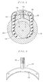
Patent Document 1. As shown inFIGS.3 to 5 , the ball screw (nut assembly) 110 has ascrew 114 on a peripheral face of which agroove 114 is spirally formed and anut 118. Thenut 118 has aspiral grove 120 formed on its peripheral surface correspondingly to thegroove 114. A plurality ofballs 122 are disposed in a transfer path configured by thegroove 114 and thegroove 120. The transfer path is also provided with acircular tube 126 for returning back aball 122 from a starting point to an end point. The ball screw (nut assembly) 110 is provided with a deflector (ball turning device) 130 in place of a tongue (not shown) of therecirculation tube 126. Thedeflector 130 is composed of abody 132 formed by bending in saddle shape a rod (usually, steel material) having a substantially circular cross-section and ascrewed shaft 134. - Scooping up the
ball 122 with the both ends of thebody 132 does not invite the defect of unsatisfactory strength, even in the case of the high-load capacity and the high-speed ball screw, as with the tongue. -
- Patent Document 1: Patent Application Publication No. H4-228963
- In the ball screw disclosed in
Patent Document 1, a fixing bolt for the deflector is provided by one at the center of the deflector. Hence, the ball screw, however, is in danger of generating vibrations in the deflector when the deflector scoops up a ball, which may loosen the fixing bolt.
Further, in the prior art, the scooping-up site of the deflector has a plane and therefore is not to be able to scoop up a ball along a screw line of the ball screw. Thus, when scooping up the ball, the ball draws a discontinuous locus, which induces problems that the scooping-up site is not qualified for high-speed use. Namely, the problems include the generation of noise, an incidence of scratch on a surface of the ball due to collision against the scooping-up site, and gripping of small pieces resulted from scraping off of the tongue in the ball grooves etc. - The present invention has made to solve the defects as such and an object thereof is to provide a ball screw preventing a fixing bolt of a deflector from being loosened.
Further, another object of the present invention is to provide a ball screw capable of implementing smooth scooping up of a ball by the deflector for noise reduction and to endure high-speed working conditions. - A ball screw according to one aspect of the present invention comprises a screw shaft having a spiral ball groove formed on its outer peripheral surface; a nut having a spiral ball groove opposing the ball screw groove of the screw shaft on its inner peripheral surface; a number of balls rolling along a spiral ball rolling path formed by the ball groove of the nut and the ball groove of the screw shaft; and a recirculation component provided on the nut for guiding so that the number of balls recirculate along the ball rolling path,
wherein the recirculation component is composed of a deflector scooping up the balls and a ball returning member returning back the scooped up balls to the ball rolling path, and the deflector is fixed to the nut by a plurality of fixing members. - A ball screw according to another aspect of the present invention comprises a screw shaft having a spiral ball groove formed on its outer peripheral surface; a nut having a spiral ball groove opposing the ball screw groove of the screw shaft on its inner peripheral surface; a number of balls rolling along a spiral ball rolling path formed by the ball groove of the nut and the ball groove of the screw shaft; and a recirculation component provided on the nut for guiding so that the number of balls recirculate along the ball rolling path,
wherein the recirculation component is composed of a deflector scoping up the balls and a ball returning member returning back the scooped up balls to the ball rolling path, and the deflector has a shape of scooping up the ball in the ball rolling member along a screw line toward the ball returning member. - In the ball screw according to yet another aspect of the present invention, a through hole of the nut opposing the ball scooping-up surface of the deflector has a concave curved surface shape of scooping up the ball in the ball rolling path along the screw line toward the ball returning member.
In the ball screw according to yet another aspect of the present invention, the ball scooping-up surface of the deflector has a concave curved surface shape of scooping up the ball in the ball rolling path along the screw line toward the ball returning path.
In the ball screw according to still another aspect of the present invention, the deflector is formed of resin material. - According to the ball screw of one embodiment of the present invention, the invention enables providing a deflector-type ball screw which is free from the generation of vibrations in the deflector and wipes out loosing of the fixing bolt, owing to the plural fixing members of the deflector.
According to the ball screw of another embodiment of the present invention, the invention allows providing a deflector-type ball screw capable of smoothly scooping up the ball with the deflector for noise reduction and to withstand high-speed working conditions. -
-
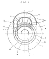
FIG. 1 is a sectional view showing an arrangement of a ball recirculation component of a ball screw according to the embodiment of the present invention; -
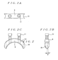
FIG. 2 is a drawing showing an arrangement of a deflector into which a bolt is inserted according to the embodiment of the present invention, in whichFIG. 2A is a plan view,FIG. 2B is a front view, andFIG. 2C is a side view; -
FIG. 3 is a plan view showing an arrangement of a ball screw disclosed inPatent Document 1; -
FIG. 4 is a sectional view taken along a line of 4-4 ofFIG. 3 ; and -
FIG. 5 is a side view showing an arrangement of a deflector disclosed inPatent Document 1. - Hereinafter, a description will be made to the first embodiment of the ball screw according to the present invention with reference to the accompanying drawings.
- As shown in
FIG. 1 , anut 2 is fitted to an outer periphery of ascrew shaft 1. A spiral ball groove 1a is formed on an outer peripheral surface of thescrew shaft 1, and a spiralboll screw groove 2a opposing the ball screw groove 1a of thescrew shaft 1 is formed on an inner peripheral surface of thenut 2. The ball screw groove 1a of thescrew shaft 1 and theball screw groove 2a of thenut 2 opposing each other constitute a spiralball rolling path 3. - Through
holes nut 2 and the throughholes ball returning member 5. Theball returning member 5 is made by bending a metal tube in substantially U-shape arranged on an outer peripheral surface of thenut 2 and the both ends thereof are inserted into the throughholes
Moreover, thedeflector 9 is disposed on the inner peripheral face of thenut 2, with the both ends thereof joined together, at a position of the both ends of theball returning path 5, and is fixed to thenut 2 with thebolt 11 that is a fixing member. - The
deflector 9 is formed by bending arcuately a metal rod whose cross-section is of a substantially elliptical form is bent. Theballs 8 in theball rolling path 3 are scooped up by the both ends of thedeflector 9 and is guided to theball returning member 5. By theball returning member 5 theballs 8 are returned back again to theball rolling path 3. Thedeflector 9 and theball returning member 5 constitute arecirculation component 17.
The throughholes recirculation component 17 constitute aconnection path 6 connecting a part and another part remote from each other of theball rolling path 3 to communicate with itself. - Thereby, the
ball rolling path 3 communicates with itself in an endless manner through the connectingpath 6 and the ball rolling path communicating in the endless manner is a ball recirculation path 7. In the ball recirculation path 7, a large number ofballs 8 made of materials such as steel and ceramic etc., are accommodated in theball rolling path 3 so as to continuously align in the endless manner therein. Theseballs 8 are endlessly recirculate in the ball recirculation path 7 when thescrew shaft 1 is rotated. The endless recirculation of theballs 8 in the recirculation path 7 permits relative movement of thenut 2 along thescrew shaft 1 with respect to thescrew shaft 1. - As shown in
FIGS. 2A, 2B, and 2C , twofemale holes 13 are formed in thedeflector 9 and thedeflector 9 is fixed to thenut 2 by the twobolts 11 inserted into twobolt insertion holes 15 formed on thenut 2.
The deflector (ball turning device) 130 of the ball screw disclosed inPatent Document 1 is fixed to thenut 118 by a fixing bolt provided by one at the center of the deflector (ball turning device) 130.
In contrast, thedeflector 9 of the ball screw according to the present invention is fixed to thenut 2 by a plurality of fixing members (bolts 11). This avoids the generation of vibrations in thedeflector 9, sweeping away a fear of loosening of the fixing member (bolt 11). - As mentioned above, in the embodiment of the present invention, an example is given where the
deflector 9 is fixed by using thebolt 11 as a fixing technique thereof. Alternatively, thedeflector 9 may be fastened and fixed by the nut (threaded fastener 136) to a threadedgrip 134 integrally provided therewith as a fixing member like thedeflector 130 disclosed inPatent Document 1 in place of thebolt 1.
Also, whereas in the instant embodiment, an example is described in which twobolts 11 are used as a fixing member, it may be three or more, not necessarily limited to two. - Hereinafter, a description of a second embodiment of the ball screw according to the present invention will next be made referring to the drawings.
As shown inFIG. 1 , thenut 2 is fitted on an outer peripheral surface of thescrew shaft 1. A spiral ball screw groove 1a is formed on an outer peripheral surface of thescrew shaft 1, and a spiralball screw groove 2a opposing the ball screw groove 1a of thescrew shaft 1 is formed on an inner peripheral surface of thenut 2. Thus, the screw ball groove 1a of thescrew shaft 1 and theball screw groove 2a of thenut 2 opposing to each other constitute the spiralball rolling path 3. - Through
holes nut 2, which are connected by theball returning member 5. Theball returning member 5 is made by bending a metal tube in substantially U-shape and arranged on a periphery of thenut 2. The both ends thereof are inserted into the throughholes
Further, thedeflector 9 is arranged on the inner peripheral surface of thenut 2, with the both ends thereof joined together, at a position of the both ends of theball returning member 5. Thedeflector 9 is fixed to thenut 2 by thebolt 11 as a fixing member. - The
deflector 9 is made by bending arcuately a metal rod whose cross-section is of a round shape. Theballs 8 in theball rolling path 3 are scooped up through the both ends of thedeflector 9 to guide it to theball returning member 5. Theballs 8 are returned back again to theball rolling path 3 with theball returning member 5. Thedeflector 9 and theball returning member 5 constitute therecirculation component 17.
The throughholes recirculation component 17 constitute the connectingpath 6 in which a part and another part of theball rolling path 3 remote from each other are connected to communicate with itself. - Thereby, the
ball rolling path 3 communicates with itself in an endless manner via the connectingpath 6. The path communicating in the endless manner is the ball recirculation path 7. A large number ofballs 8 made of materials such as steel and ceramic etc., are accomodated in the ball recirculation path 7 so as to continuously align in the endless manner in the ball recirculation path 7 and roll in the ball rolling path 7 for endless recirculation when thescrew shaft 1 is rotated.
The endless recirculation of theballs 8 in the ball recirculation path 7 allows relative movement of thenut 2 along thescrew shaft 1 relative to thescrew shaft 1. - As shown in
FIGS. 2A, 2B, and 2C , thedeflector 9 has twofemale holes 13 formed thereon with which thedeflector 9 is fixed to thenut 2 by twobolts 11 inserted into the two bolt insertion holes 15 formed on the nut 12.
The deflector (ball turning device) 13 of the ball screw disclosed inPatent Document 1 is fixed to thenut 118 by the fixing bolt provided by one at the center of the deflector (ball returning device)130. - On the contrary, in the ball screw of the present invention, the
deflector 9 is fixed to thenut 2 by the plurality of fixing members (bolts 11). This avoids the generation of vibrations in thedeflector 9, seeping away a fear of loosening of the fixing members (bolts 11).
As shown inFIG. 2A , a cross-section perpendicular to a scooping-up direction of theball 8 of the scooping-upsurface 19 of thedeflector 9 is a concave curved surface having a radius of curvature slightly larger than a radius of theball 8. This concave curved surface is of a shape of scooping up theball 8 in a tangential direction of a screw line of theball 8 ejected from theball rolling path 3. - Moreover, a cross-section perpendicular to a according-up direction of the
ball 8 of the throughholes nut 2 opposing the scooping-upsurface 19 of thedeflector 9 is a concave curved surface having a radius of curvature slightly larger than a radius of theball 8, as with the scooping-up surface of thedeflector 9. The concave curved surface is of a shape of scooping up theball 8 ejected from theball rolling path 3 in a tangential direction of the screw line.
Herein, the screw line refers to a center locus of the spiral ball moving in theball rolling path 3. The tangential direction of the screw line is, more specifically, a tangential direction of adiameter 25 of a pitch circle of theball 8 in theball rolling path 3 inFIG. 1 , and a direction slant just a lead angle of θ of ball groove 1a of theball shaft 1. - In the present embodiment, the cross-section perpendicular to the scooping-up direction of the
ball 8 of the scooping-upsurface 19 of thedeflector 9 and the surface of the throughholes nut 2 facing the scooping-up surface are the concave curved surface having the radius of curvature slightly larger than the radius of theball 8. The concave curved surface is of the shape of scooping up theball 8 ejected from theball rolling path 3 in the tangential direction of the screw line. Nonetheless, the concave curved surface has only to be provided at least in the throughholes nut 2. The scooping-upsurface 19 of thedeflector 9 may be a plane scooping up theball 8 in the tangential direction of the screw line. - In this way, the
balls 8 ejected from theball rolling path 3 are scooped up in the tangential direction by thedeflector 9. Therefore, the arrangement provides a deflection-type ball screw capable of smoothly scooping up theball 8 for noise reduction and of being endure high-speed working conditions.
Furthermore, in addition to that thedeflector 9 is fixed to thenut 2 by the plurality of fixing members (bolts 11), theball 8 is smoothly scooped up along the screw line, which suppresses the generation of vibrations in thedeflector 9, further preventing loosening of the fixed bolt. - Hereinafter, a description of a third embodiment of the ball screw according to the present invention will be made referring to drawings.
As shown inFIG. 1 , thenut 2 is fitted to the outer peripheral surface of thescrew shaft 1. The spiral ball screw grove 1a is formed on the outer peripheral surface of thescrew shaft 1, and thespiral ball groove 2a opposing the spiral ball groove 1a of thescrew shaft 1 is formed on the inner peripheral surface of thenut 2. Then, the ball screw groove 1a of thescrew shaft 1 and theball screw groove 2a of thenut 2 constitute the spiralball rolling path 3. - The through
holes nut 2, which are connected withball returning member 5. Theball returning member 5 is made by bending the metal tube in substantially U-shape and is arranged at a periphery of thenut 2. The both ends thereof are inserted into the throughholes
Furthermore, thedeflector 9 is arranged on the inner peripheral surface of thenut 2, with the both ends thereof joined together, at a position of the both ends of theball returning member 5, and is fixed to thenut 2 by thebolt 11 that is a fixing member. - The
deflector 9 is of a round shape in a right-angled cross-section with respect to a longitudinal direction, and has a partially arcuate shape on the whole. Thedeflector 9 is molded by resin materials (e.g., engineering plastic such as polyacetal resin and reinforcing material contained polyamide resin). Theballs 8 in theball rolling path 3 are scooped up by the both ends of thedeflector 9 and is guided to theball returning member 5. The returningmember 5 returns back again theballs 8 to theball rolling path 3. Thedeflector 9 and theball returning member 5 constitute therecirculation component 17. - The through
holes recirculation component 17 constitute the connectingpart 6 connecting a part and another part remote from each other to communicate with itself.
Thereby, theball rolling path 3 communicates with itself in the endless manner through the connectingpath 6. The path connected in the endless manner is the ball recirculation component 7. A large number ofballs 8 made of materials such as steel and ceramic etc., are accommodated in the ball recirculation path 7 so as to continuously align in the endless manner therein, and roll in the ball recirculation path 7 when thescrew shaft 1 is rotated for endless recirculation.
The endless recirculation of theballs 8 in the ball recirculation path 7 enables relative movement of thenut 2 along thescrew shaft 1 with respect to thescrew shaft 1. - As shown in
FIGS. 2A, 2B, and 2C , thedeflector 9 has two female screw holes 3 formed therein with which thedeflector 9 is fixed to thenut 2 by twobolts 11 inserted into the two bolt insertion holes 15 formed on thenut 2.
The deflector 130 (ball returning device) 130 of the ball screw disclosed inPatent Document 1 is fixed to thenut 118 by the fixing bolt provided by one at the center thereof. - On the contrary, in the ball screw of the present invention, the fixation of the
deflector 9 to thenut 2 by the plurality of fixing members (bolts 11) suppress the generation of vibrations in thedeflector 9, thereby eliminating a fear of loosening the fixing members (bolts 11).
The cross-section perpendicular to the scooping-up direction of theball 8 of the scooping-upsurface 19 of thedeflector 9 is, as shown inFIG. 2A , of a shape of concave curved surface having the radius of curvature slightly larger than the radius of theball 8. The concave curved surface is of a shape of scooping up theball 8 ejected from theball rolling path 2 in a tangential direction. - Further, the cross-section perpendicular to the scooping-up direction of the
ball 8 of the throughholes nut 2 opposing the scooping-upsurface 19 of thedeflector 9, as with the scooping-upsurface 19 of thedeflector 9, are a concave curved surface having the radius of curvature slightly larger than the radius of theball 8. The concave curved surface is of a shape of scooping up theball 8 ejected from theball rolling path 3 in a tangential direction of the screw line.
Herein, the screw line refers to a central locus of the spiral ball moving in theball recirculation path 3. The tangential direction of the screw line is, more specifically, a tangential direction of adiameter 25 of a pitch circle of theball 8 in theball rolling path 3, inFIG. 1 , and a direction slant just a lead angle of θ of the ball screw groove 1a of thescrew shaft 1, as shown inFIG. 2B . - In the instant embodiment, the cross-section perpendicular to the scooping-up direction of the
ball 8 of the scooping-upsurface 19 of thedeflector 9 and the surface of the throughholes nut 2 opposing the scooping-up surface are the concave curved surface having the radius of curvature slightly larger than the radius of theball 8. The concave curved surface are of a shape of scooping up theball 8 ejected from theball rolling path 3 in the tangential direction of the screw line. Nonetheless, it has only to provide the concave curved surface of scooping up theballs 8 in the tangential direction of the ball line at least in the throughholes nut 2. Instead, the scooping-upsurface 19 of thedeflector 9 may be a surface of scooping up theball 9 in a tangential direction of the screw line. - In this way, scooping up of the
ball 8 ejected from theball rolling path 3 by thedeflector 9 in the tangential direction of the screw line reduces noise owing to smooth scooping up of theball 8, which provides a deflector-type ball screw capable of withstanding high-speed working conditions. Moreover, the formation of thedeflector 8 with resin material further reduces noise in corporation with scooping up of the ball in the tangential direction of the screw line. - In addition to the fixation of the
deflector 9 to thenut 2 by the plurality of fixing members (bolts 11), smooth scooping up of theball 8 along the screw line avoids the generation of vibrations in thedeflector 9, still more preventing loosening of the fixing bolt.
While the description of the embodiments of the present invention has made haretofore, the present invention may have various modifications and improvements, not necessarily limited thereto. - The present invention can find its wide application to various mechanical devices as the ball screw with the recirculation-type deflector.
-
- 1: Ball shaft
- 1a: Ball screw groove (at screw shaft side)
- 2: Nut
- 2a: Ball screw groove (at nut side)
- 3: ball rolling path
- 5: Ball returning member
- 8: Ball
- 9: deflector
- 10: Ball screw
- 11: Fixing member (bolt)
- 17: Recirculation component
- 19: Scooping-up surface
Claims (5)
- A ball screw comprising:a screw shaft having a spiral ball groove formed on its outer peripheral surface;a nut having a spiral ball groove opposing the ball screw groove of the screw shaft on its inner peripheral surface;a number of balls rolling along a spiral ball rolling path formed by the ball groove of the nut and the ball groove of the screw shaft; anda recirculation component provided on the nut for guiding so that the number of balls recirculate along the ball rolling path,wherein the recirculation component is composed of a deflector scooping up the balls and a ball returning member returning back the scooped up balls to the ball rolling path, and the deflector is fixed to the nut by a plurality of fixing members.
- A ball screw comprising:a screw shaft having a spiral ball groove formed on its outer peripheral surface;a nut having a spiral ball groove opposing the ball screw groove of the screw shaft on its inner peripheral surface;a number of balls rolling along a spiral ball rolling path formed by the ball groove of the nut and the ball groove of the screw shaft; anda recirculation component provided on the nut for guiding so that the number of balls recirculate along the ball rolling path,wherein the recirculation component is composed of a deflector scooping up the balls and a ball returning member returning back the scooped up balls to the ball rolling path, and the deflector has a shape of scooping up the balls in the ball rolling member along a screw line toward the ball returning member.
- The ball screw according to claim 2, wherein a through hole of the nut opposing the ball scooping-up surface of the deflector has a concave curved surface shape of scooping up the ball in the ball rolling path along the screw line toward the ball returning member.
- The ball screw according to claim 2 or 3, wherein the ball scooping-up surface of the deflector has a concave curved surface shape of scooping up the ball in the ball rolling path along the screw line toward the ball returning path.
- The ball screw according to any one of claims 2 to 4, wherein the deflector is formed of resin material.
Applications Claiming Priority (4)
| Application Number | Priority Date | Filing Date | Title |
|---|---|---|---|
| JP2009294037 | 2009-12-25 | ||
| JP2010012167 | 2010-01-22 | ||
| JP2010034491 | 2010-02-19 | ||
| PCT/JP2010/006420 WO2011077622A1 (en) | 2009-12-25 | 2010-10-29 | Ball screw |
Publications (2)
| Publication Number | Publication Date |
|---|---|
| EP2360395A1 true EP2360395A1 (en) | 2011-08-24 |
| EP2360395A4 EP2360395A4 (en) | 2012-11-07 |
Family
ID=44195176
Family Applications (1)
| Application Number | Title | Priority Date | Filing Date |
|---|---|---|---|
| EP10808963A Withdrawn EP2360395A4 (en) | 2009-12-25 | 2010-10-29 | Ball screw |
Country Status (5)
| Country | Link |
|---|---|
| US (1) | US20120132025A1 (en) |
| EP (1) | EP2360395A4 (en) |
| JP (1) | JP5712933B2 (en) |
| CN (1) | CN102171490A (en) |
| WO (1) | WO2011077622A1 (en) |
Families Citing this family (8)
| Publication number | Priority date | Publication date | Assignee | Title |
|---|---|---|---|---|
| JP5741533B2 (en) * | 2011-08-03 | 2015-07-01 | 日本精工株式会社 | Ball screw manufacturing method and ball screw |
| US20150152946A1 (en) * | 2013-12-04 | 2015-06-04 | Nook Industries, Inc. | Ball screw assembly |
| JP6295469B2 (en) * | 2014-02-27 | 2018-03-20 | 日立オートモティブシステムズ株式会社 | Power steering device and method of manufacturing power steering device |
| DE102015209643B3 (en) * | 2015-05-27 | 2016-11-10 | Schaeffler Technologies AG & Co. KG | Ball Screw |
| JP6503446B1 (en) * | 2017-12-20 | 2019-04-17 | 上銀科技股▲分▼有限公司 | Ball screw |
| CN109595318A (en) * | 2018-12-27 | 2019-04-09 | 宁波海迈克精密机械制造有限公司 | A kind of circulation member of ball-screw |
| CN109654190A (en) * | 2018-12-27 | 2019-04-19 | 宁波海迈克精密机械制造有限公司 | A kind of ball-screw |
| CN113251125A (en) * | 2021-04-13 | 2021-08-13 | 浙江卓求传动科技有限公司 | Totally-enclosed low-noise ball nut |
Family Cites Families (35)
| Publication number | Priority date | Publication date | Assignee | Title |
|---|---|---|---|---|
| US2636397A (en) * | 1951-02-08 | 1953-04-28 | Cleveiand Pneumatic Tool Compa | Ball deflector and screw cleaner for ball-bearing screw and nut assemblies |
| US3529486A (en) * | 1968-09-04 | 1970-09-22 | Gen Motors Corp | Ball deflector for ball screw and nut devices |
| US3661030A (en) * | 1970-05-18 | 1972-05-09 | Precise Services Inc | Ball screw and nut combination |
| FR2204270A5 (en) * | 1972-10-20 | 1974-05-17 | Tech Integrale S | |
| JPS50155869A (en) * | 1974-06-10 | 1975-12-16 | ||
| US5014568A (en) | 1990-02-28 | 1991-05-14 | Dana Corporation | Deflector for ball screw and nut assembly |
| JPH0635719U (en) * | 1992-10-19 | 1994-05-13 | 光洋機械工業株式会社 | Ball screw |
| US6023991A (en) * | 1993-06-21 | 2000-02-15 | Nsk Ltd. | Ball screw lubricated with oil-containing polymer |
| US5373755A (en) * | 1993-07-30 | 1994-12-20 | Dana Corporation | Skirt deflector for a ball nut and screw device |
| JPH11257454A (en) * | 1998-03-06 | 1999-09-21 | Koyo Mach Ind Co Ltd | Ball screw |
| DE10012810A1 (en) * | 2000-03-16 | 2001-09-27 | Rexroth Star Gmbh | Rolling body screw drive has at least one re-orientation element fastened to threaded nut encompassing threaded spindle by means of fixing pins extending parallel to spindle's longitudinal axis |
| US6681651B2 (en) * | 2000-07-18 | 2004-01-27 | Thk Co., Ltd. | Ball screw |
| JP2002295625A (en) * | 2001-03-30 | 2002-10-09 | Ntn Corp | Ball screw |
| JP4288903B2 (en) * | 2001-07-30 | 2009-07-01 | 日本精工株式会社 | Ball screw device |
| JP3948973B2 (en) * | 2002-02-07 | 2007-07-25 | Thk株式会社 | Screw device with lubricant application function |
| JP4053826B2 (en) * | 2002-06-25 | 2008-02-27 | Thk株式会社 | Circulating component, and motion guide device and ball screw using the circulating component |
| JP3878068B2 (en) * | 2002-06-26 | 2007-02-07 | 株式会社ジェイテクト | Deflector-type ball screw device and manufacturing method thereof |
| JP2004108455A (en) * | 2002-09-17 | 2004-04-08 | Nsk Ltd | Ball screw device |
| JP2004116688A (en) * | 2002-09-27 | 2004-04-15 | Ntn Corp | Ball screw |
| EP1515066B1 (en) * | 2003-09-10 | 2014-01-08 | Nsk Ltd | Ball screw apparatus |
| JP2005155887A (en) * | 2003-10-30 | 2005-06-16 | Nsk Ltd | Ball screw device |
| DE102004023353A1 (en) * | 2004-05-12 | 2005-12-08 | Ina-Schaeffler Kg | Ball Screw |
| JP2005351340A (en) * | 2004-06-09 | 2005-12-22 | Nsk Ltd | Ball screw device |
| JP2006002923A (en) * | 2004-06-21 | 2006-01-05 | Nsk Ltd | Ball screw device |
| EP1624228B1 (en) * | 2004-08-06 | 2011-10-12 | NSK Ltd. | Ball circulating member and ball screw |
| CN100480545C (en) * | 2004-10-29 | 2009-04-22 | Thk株式会社 | Screw device |
| JP2006153181A (en) * | 2004-11-30 | 2006-06-15 | Nsk Ltd | Linear motion device |
| US7234368B1 (en) * | 2005-11-15 | 2007-06-26 | Hiwin Technologies Corp. | Ball screw device having lubricating structure |
| CN101432550B (en) * | 2006-04-28 | 2012-05-02 | Thk株式会社 | Screw device and manufacturing method thereof |
| JP2008202669A (en) * | 2007-02-19 | 2008-09-04 | Thk Co Ltd | Screw device series and screw device |
| JP2008202672A (en) * | 2007-02-19 | 2008-09-04 | Thk Co Ltd | Ball screw and its manufacturing method |
| US20090071272A1 (en) * | 2007-09-18 | 2009-03-19 | Hiwin Technologies Corp. | Ball screw device having circulating device |
| US7934438B2 (en) * | 2007-10-31 | 2011-05-03 | Hiwin Technologies Corp. | Ball screw device having circulating device background of the invention |
| JP5037323B2 (en) * | 2007-12-11 | 2012-09-26 | 黒田精工株式会社 | Ball screw device |
| US20100126292A1 (en) * | 2008-11-25 | 2010-05-27 | Hiwin Technologies Corp. | Deflector for ball screw device |
-
2010
- 2010-10-29 CN CN2010800021633A patent/CN102171490A/en active Pending
- 2010-10-29 US US13/056,010 patent/US20120132025A1/en not_active Abandoned
- 2010-10-29 EP EP10808963A patent/EP2360395A4/en not_active Withdrawn
- 2010-10-29 WO PCT/JP2010/006420 patent/WO2011077622A1/en not_active Ceased
- 2010-10-29 JP JP2011547247A patent/JP5712933B2/en active Active
Also Published As
| Publication number | Publication date |
|---|---|
| CN102171490A (en) | 2011-08-31 |
| WO2011077622A1 (en) | 2011-06-30 |
| EP2360395A4 (en) | 2012-11-07 |
| JPWO2011077622A1 (en) | 2013-05-02 |
| JP5712933B2 (en) | 2015-05-07 |
| US20120132025A1 (en) | 2012-05-31 |
Similar Documents
| Publication | Publication Date | Title |
|---|---|---|
| US20120132025A1 (en) | Ball Screw | |
| US8336415B2 (en) | Roller screw | |
| CN101842612B (en) | Rolling-body screw device | |
| US9927011B2 (en) | Ball screw | |
| US8925413B2 (en) | Rolling element screw assembly | |
| TWI435986B (en) | Roller screw and roller screw roller circulation method | |
| US20060027038A1 (en) | Ball screw device | |
| JP4941151B2 (en) | Ball screw device | |
| WO2005043007A1 (en) | Ball screw device | |
| US8272289B2 (en) | Roller screw | |
| EP2151895A3 (en) | A nut and a housing | |
| CA2477280A1 (en) | Milk collecting piece with a kink element for defining kinking of a milk tube | |
| US20040141828A1 (en) | Device for mounting a component such as a pipe on a stud | |
| JP2007255435A (en) | Rolling element screw device and manufacturing method for rolling element screw device | |
| EP2580029B1 (en) | A tool flange for an industrial robot | |
| EP1624228B1 (en) | Ball circulating member and ball screw | |
| JP2012132538A (en) | Deflector type ball screw | |
| JP2012072868A (en) | Deflector type ball screw | |
| JP2009103199A (en) | Ball screw | |
| JP2013050208A (en) | Method for manufacturing ball screw, and the ball screw | |
| CN222363577U (en) | A bent pipe fitting | |
| KR100351958B1 (en) | Connecting ring of dredging road | |
| JP2009030809A (en) | Ball screw | |
| JP2017214995A (en) | Screw and structure including the same | |
| JP2023064311A (en) | Joint structure |
Legal Events
| Date | Code | Title | Description |
|---|---|---|---|
| PUAI | Public reference made under article 153(3) epc to a published international application that has entered the european phase |
Free format text: ORIGINAL CODE: 0009012 |
|
| 17P | Request for examination filed |
Effective date: 20110207 |
|
| AK | Designated contracting states |
Kind code of ref document: A1 Designated state(s): AL AT BE BG CH CY CZ DE DK EE ES FI FR GB GR HR HU IE IS IT LI LT LU LV MC MK MT NL NO PL PT RO RS SE SI SK SM TR |
|
| A4 | Supplementary search report drawn up and despatched |
Effective date: 20121005 |
|
| RIC1 | Information provided on ipc code assigned before grant |
Ipc: F16H 25/22 20060101AFI20120928BHEP |
|
| DAX | Request for extension of the european patent (deleted) | ||
| 17Q | First examination report despatched |
Effective date: 20131004 |
|
| STAA | Information on the status of an ep patent application or granted ep patent |
Free format text: STATUS: THE APPLICATION IS DEEMED TO BE WITHDRAWN |
|
| 18D | Application deemed to be withdrawn |
Effective date: 20141210 |