EP2360354A2 - Rankine Cycle System - Google Patents
Rankine Cycle System Download PDFInfo
- Publication number
- EP2360354A2 EP2360354A2 EP10186737A EP10186737A EP2360354A2 EP 2360354 A2 EP2360354 A2 EP 2360354A2 EP 10186737 A EP10186737 A EP 10186737A EP 10186737 A EP10186737 A EP 10186737A EP 2360354 A2 EP2360354 A2 EP 2360354A2
- Authority
- EP
- European Patent Office
- Prior art keywords
- expander
- working fluid
- heat
- rankine cycle
- coupled
- Prior art date
- Legal status (The legal status is an assumption and is not a legal conclusion. Google has not performed a legal analysis and makes no representation as to the accuracy of the status listed.)
- Withdrawn
Links
- 239000012530 fluid Substances 0.000 claims abstract description 82
- 239000002918 waste heat Substances 0.000 claims description 12
- 238000011084 recovery Methods 0.000 claims description 10
- 238000006073 displacement reaction Methods 0.000 claims description 7
- 230000020169 heat generation Effects 0.000 claims description 4
- 238000009833 condensation Methods 0.000 claims description 2
- 230000005494 condensation Effects 0.000 claims description 2
- 238000001704 evaporation Methods 0.000 claims description 2
- 230000008020 evaporation Effects 0.000 claims description 2
- RGSFGYAAUTVSQA-UHFFFAOYSA-N Cyclopentane Chemical compound C1CCCC1 RGSFGYAAUTVSQA-UHFFFAOYSA-N 0.000 description 8
- ATUOYWHBWRKTHZ-UHFFFAOYSA-N Propane Chemical compound CCC ATUOYWHBWRKTHZ-UHFFFAOYSA-N 0.000 description 8
- YTPLMLYBLZKORZ-UHFFFAOYSA-N Thiophene Chemical compound C=1C=CSC=1 YTPLMLYBLZKORZ-UHFFFAOYSA-N 0.000 description 8
- NVSXSBBVEDNGPY-UHFFFAOYSA-N 1,1,1,2,2-pentafluorobutane Chemical compound CCC(F)(F)C(F)(F)F NVSXSBBVEDNGPY-UHFFFAOYSA-N 0.000 description 4
- XDTMQSROBMDMFD-UHFFFAOYSA-N Cyclohexane Chemical compound C1CCCCC1 XDTMQSROBMDMFD-UHFFFAOYSA-N 0.000 description 4
- 239000004721 Polyphenylene oxide Substances 0.000 description 4
- 239000001273 butane Substances 0.000 description 4
- 239000007789 gas Substances 0.000 description 4
- -1 ground Substances 0.000 description 4
- DMEGYFMYUHOHGS-UHFFFAOYSA-N heptamethylene Natural products C1CCCCCC1 DMEGYFMYUHOHGS-UHFFFAOYSA-N 0.000 description 4
- 150000002576 ketones Chemical class 0.000 description 4
- 239000007788 liquid Substances 0.000 description 4
- IJDNQMDRQITEOD-UHFFFAOYSA-N n-butane Chemical compound CCCC IJDNQMDRQITEOD-UHFFFAOYSA-N 0.000 description 4
- OFBQJSOFQDEBGM-UHFFFAOYSA-N n-pentane Natural products CCCCC OFBQJSOFQDEBGM-UHFFFAOYSA-N 0.000 description 4
- 239000003921 oil Substances 0.000 description 4
- MSSNHSVIGIHOJA-UHFFFAOYSA-N pentafluoropropane Chemical compound FC(F)CC(F)(F)F MSSNHSVIGIHOJA-UHFFFAOYSA-N 0.000 description 4
- 229940029560 pentafluoropropane Drugs 0.000 description 4
- 229920000570 polyether Polymers 0.000 description 4
- 239000001294 propane Substances 0.000 description 4
- 229930192474 thiophene Natural products 0.000 description 4
- 238000002485 combustion reaction Methods 0.000 description 3
- MWUXSHHQAYIFBG-UHFFFAOYSA-N nitrogen oxide Inorganic materials O=[N] MWUXSHHQAYIFBG-UHFFFAOYSA-N 0.000 description 3
- 230000005611 electricity Effects 0.000 description 2
- 239000000446 fuel Substances 0.000 description 2
- VNWKTOKETHGBQD-UHFFFAOYSA-N methane Chemical compound C VNWKTOKETHGBQD-UHFFFAOYSA-N 0.000 description 2
- 238000012986 modification Methods 0.000 description 2
- 230000004048 modification Effects 0.000 description 2
- 230000000712 assembly Effects 0.000 description 1
- 238000000429 assembly Methods 0.000 description 1
- 238000009835 boiling Methods 0.000 description 1
- 238000010960 commercial process Methods 0.000 description 1
- 238000001816 cooling Methods 0.000 description 1
- 239000000498 cooling water Substances 0.000 description 1
- 239000002283 diesel fuel Substances 0.000 description 1
- 230000005674 electromagnetic induction Effects 0.000 description 1
- 239000003502 gasoline Substances 0.000 description 1
- 238000010438 heat treatment Methods 0.000 description 1
- 238000004519 manufacturing process Methods 0.000 description 1
- 238000000034 method Methods 0.000 description 1
- 239000003345 natural gas Substances 0.000 description 1
- 239000010773 plant oil Substances 0.000 description 1
- 238000010248 power generation Methods 0.000 description 1
- XLYOFNOQVPJJNP-UHFFFAOYSA-N water Substances O XLYOFNOQVPJJNP-UHFFFAOYSA-N 0.000 description 1
Images


Classifications
-
- F—MECHANICAL ENGINEERING; LIGHTING; HEATING; WEAPONS; BLASTING
- F01—MACHINES OR ENGINES IN GENERAL; ENGINE PLANTS IN GENERAL; STEAM ENGINES
- F01K—STEAM ENGINE PLANTS; STEAM ACCUMULATORS; ENGINE PLANTS NOT OTHERWISE PROVIDED FOR; ENGINES USING SPECIAL WORKING FLUIDS OR CYCLES
- F01K25/00—Plants or engines characterised by use of special working fluids, not otherwise provided for; Plants operating in closed cycles and not otherwise provided for
- F01K25/08—Plants or engines characterised by use of special working fluids, not otherwise provided for; Plants operating in closed cycles and not otherwise provided for using special vapours
-
- F—MECHANICAL ENGINEERING; LIGHTING; HEATING; WEAPONS; BLASTING
- F01—MACHINES OR ENGINES IN GENERAL; ENGINE PLANTS IN GENERAL; STEAM ENGINES
- F01K—STEAM ENGINE PLANTS; STEAM ACCUMULATORS; ENGINE PLANTS NOT OTHERWISE PROVIDED FOR; ENGINES USING SPECIAL WORKING FLUIDS OR CYCLES
- F01K13/00—General layout or general methods of operation of complete plants
- F01K13/02—Controlling, e.g. stopping or starting
-
- F—MECHANICAL ENGINEERING; LIGHTING; HEATING; WEAPONS; BLASTING
- F01—MACHINES OR ENGINES IN GENERAL; ENGINE PLANTS IN GENERAL; STEAM ENGINES
- F01K—STEAM ENGINE PLANTS; STEAM ACCUMULATORS; ENGINE PLANTS NOT OTHERWISE PROVIDED FOR; ENGINES USING SPECIAL WORKING FLUIDS OR CYCLES
- F01K7/00—Steam engine plants characterised by the use of specific types of engine; Plants or engines characterised by their use of special steam systems, cycles or processes; Control means specially adapted for such systems, cycles or processes; Use of withdrawn or exhaust steam for feed-water heating
- F01K7/02—Steam engine plants characterised by the use of specific types of engine; Plants or engines characterised by their use of special steam systems, cycles or processes; Control means specially adapted for such systems, cycles or processes; Use of withdrawn or exhaust steam for feed-water heating the engines being of multiple-expansion type
- F01K7/025—Consecutive expansion in a turbine or a positive displacement engine
Definitions
- the invention relates generally to rankine cycle system, and more particularly to a rankine cycle system having a variable speed expander.
- Enormous amounts of waste heat are generated by a wide variety of industrial and commercial processes and operations.
- Example sources of waste heat include heat from space heating assemblies, steam boilers, engines, and cooling systems.
- waste heat is low grade, such as waste heat having a temperature of heat below 840 degrees Fahrenheit, for example, conventional heat recovery systems do not operate with sufficient efficiency to make recovery of energy cost-effective. The net result is that vast quantities of waste heat are simply dumped into the atmosphere, ground, or water.
- Some power generation systems provide better reliability and off-grid operation with alternate fuels such as biogas or landfill gas, with examples being gas turbines and combustion engines such as microturbines and reciprocating engines.
- Combustion engines may be used to generate electricity using fuels such as gasoline, natural gas, biogas, plant oil, and diesel fuel.
- fuels such as gasoline, natural gas, biogas, plant oil, and diesel fuel.
- atmospheric emissions such as nitrogen oxides and particulates may be emitted.
- a fundamental rankine cycle typically includes a turbo generator, an evaporator/boiler, a condenser, and a liquid pump.
- the turbo generator of conventional rankine cycle is operated at fixed speed.
- conventional rankine cycle has constraints that it can operate only at design state points (pressures, mass flows and temperatures).
- design state points pressures, mass flows and temperatures.
- the rankine cycle can only be operated at a limited range of state points. As a result, the cycle efficiency is lowered and component operation limits are exceeded.
- a rankine cycle system in accordance with one exemplary embodiment of the present invention, includes an evaporator coupled to a heat source and configured to circulate a working fluid in heat exchange relationship with a hot fluid from the heat source so as to heat the working fluid and vaporize the working fluid.
- An expander is coupled to the evaporator and configured to expand the vaporized working fluid from the evaporator.
- the exemplary expander is operable at variable speed.
- a condenser is coupled to the expander and configured to condense the vaporized working fluid from the expander.
- a pump is coupled to the condenser and configured to feed the condensed working fluid from the condenser to the evaporator.
- a waste heat recovery system including at least two integrated rankine cycle systems having an expander operable at variable speed is disclosed.
- a rankine cycle system in accordance with exemplary embodiments of the present invention, includes an evaporator coupled to a heat source and configured to circulate a working fluid in heat exchange relationship with a hot fluid from the heat source so as to heat the working fluid and vaporize the working fluid.
- An expander is coupled to the evaporator and configured to expand the vaporized working fluid from the evaporator.
- the exemplary expander is operable at variable speed.
- a condenser is coupled to the expander and configured to condense the vaporized working fluid from the expander.
- a pump is coupled to the condenser and configured to feed the condensed working fluid from the condenser to the evaporator.
- a waste heat recovery system including at least two integrated rankine cycle systems having an expander operable at variable speed is disclosed.
- a rankine cycle system 10 is illustrated in accordance with an exemplary embodiment of the present invention.
- a working fluid is circulated through the rankine cycle system 10.
- the working fluid may be an organic working fluid and may include cyclohexane, cyclopentane, thiophene, ketones, aromatics, propane, butane, pentafluoro-propane, pentafluoro-butane, pentafluoro-polyether, or combinations thereof. It should be noted herein that list of working fluids are not inclusive and other working fluids applicable to rankine cycles are also envisaged.
- the rankine cycle system 10 includes an evaporator 12 coupled to a heat source 14, for example an exhaust unit of a heat generation system (for example, an engine).
- the evaporator 12 receives heat from a hot fluid generated from the heat source 14 and generates a working fluid vapor.
- the vaporized working fluid is passed through an expander 16 to drive a generator 18 configured to generate power.
- the expander 16 may be at least one radial type expander, axial type expander, high temperature screw type or impulse type expander, positive displacement type expander.
- the working fluid vapor at a relatively lower pressure and lower temperature is passed through a condenser 20.
- the working fluid vapor is condensed into a liquid, which is then pumped via a pump 22 to the evaporator 12. The cycle may then be repeated.
- the expander 16 is directly coupled to the generator 18 configured to generate power.
- the speed of the expander 16 is operable at variable speed.
- the exemplary generator 18 is an asynchronous generator. In such generators, if the revolutions per minute are held constant, the frequency varies depending on the power level. The peaks of the sinusoidal waveform have no fixed relationship with a rotor position. The magnetic field of a rotor is generated via a stator through electromagnetic induction.
- the exemplary rankine cycle system 10 does not have constraints that it can operate only at design state points (pressures, mass flows and temperatures).
- the expander 16 and the generator 18 are operable at variable speeds during partial load conditions or off design operating conditions.
- the rankine cycle system 10 can be operated at a wide range of state points. As a result, the cycle efficiency is increased and component operation limits are not exceeded.
- the illustrated waste heat recovery system 24 includes a first organic rankine cycle system 26 (top cycle) and a second organic rankine cycle system 28 (bottom cycle).
- a first organic working fluid is circulated through the first organic rankine cycle system 26.
- the first organic working fluid may include cyclohexane, cyclopentane, thiophene, ketones, aromatics, or combinations thereof.
- the first organic rankine cycle system 26 includes an evaporator 30 coupled to a first heat source 32, for example an exhaust unit of a heat generation system 34 (for example, an engine).
- the evaporator 30 receives heat from the exhaust gas generated from the first heat source 32 and generates a first organic working fluid vapor.
- the first organic working fluid vapor is passed through a first expander 36 to drive a first generator 38.
- the first expander may be radial type expander, axial type expander, impulse type expander, or high temperature screw type expander, positive displacement type expander.
- the first organic working fluid vapor at a relatively lower pressure and lower temperature is passed through a cascaded heat exchange unit 40.
- the first organic working fluid vapor is condensed into a liquid, which is then pumped via a pump 42 to the evaporator 30. The cycle may then be repeated.
- the cascaded heat exchange unit 40 is used both as a condenser for the first organic rankine cycle system 26 and as evaporator for the second organic rankine cycle system 28.
- a second organic working fluid is circulated through the second organic rankine cycle system 28.
- the second organic working fluid may include propane, butane, pentafluoro-propane, pentafluoro-butane, pentafluoro-polyether, oil, or combinations thereof. It should be noted herein that list of first and second organic working fluids are not inclusive and other organic working fluids applicable to organic rankine cycles are also envisaged.
- Cascaded heat exchange unit 40 may be coupled to any one or more of a plurality of second heat sources such as an intercooler 44, an oil heat exchanger 46, and a cooling water jacket heat exchanger 48. Such second heat sources are also typically coupled to the engine. It should be noted herein that the second heat source includes a lower temperature heat source than the first heat source. It should be noted that in other exemplary embodiments, first and second heat sources may include other multiple low-grade heat sources such as gas turbines with intercoolers.
- the cascaded heat exchange unit 40 receives heat from the first organic working fluid and generates a second organic working fluid vapor. The second organic working fluid vapor is passed through a second expander 50 to drive a second generator 52.
- the second expander 50 may be a radial type expander, an axial type expander, high temperature screw type or an impulse type expander, positive displacement type expander.
- neither of the first and second organic working fluids are expanded below the atmospheric pressure, and the boiling point temperature of the first organic working fluid is below the average temperature of the second heat source.
- the second organic working fluid vapor at lower pressure and lower temperature is passed through a condenser 54.
- the second organic working fluid vapor is condensed into a liquid, which is then pumped via a pump 56 to the second heat sources. The cycle may then be repeated.
- second heat sources such as intercoolers, oil heat exchangers, jacket heat exchangers, evaporators and their relative positions explained in greater detail in U.S. Patent Application 11/770,895 is incorporated herein by reference.
- the expanders 38, 52 are coupled to the generators 38, 52 respectively configured to generate power.
- the speed of the expanders 38, 52 are operable at variable speed.
- the exemplary generators 38, 52 are asynchronous generators.
- the system 58 includes a multi-stage expander 60 having an expander first stage 62 and an expander second stage 64.
- the multi-stage expander may include more than two stages.
- the expander 60 is a multi-screw expander.
- the expander first stage 62 and the expander second stage 64 are coupled to a generator 66 via a gearbox 68.
- the generator 66 is an asynchronous generator.
- a gear ratio of the gearbox 68 may be varied to vary the speed of the expander 60.
- the vaporized working fluid is passed through the expander first stage 62 and then through the expander second stage 64 to drive the generator 66 configured to generate power.
- the vaporized working fluid is expanded successively through the stages 62, 64. After expanding through the stages 62, 64, the working fluid vapor at a relatively lower pressure and lower temperature is passed through a condenser.
- the system 70 includes a multi-stage expander 72 having an expander first stage 74 and an expander second stage 76.
- the expander 72 is a multi-screw expander.
- the expander first stage 74 and the expander second stage 76 are coupled directly to a generator 78.
- the generator 78 is an asynchronous generator.
- the vaporized working fluid is passed through the expander first stage 74 and then through the expander second stage 76 to drive the generator 78 configured to generate power.
- the working fluid vapor at a relatively lower pressure and lower temperature is passed through a condenser.
- the asynchronous generator 78 is operable at variable speed so as to control the speed of the expander 72.
- the exemplary generator 78 is coupled to a frequency inverter 80 configured to vary the speed of the generator 78.
- the frequency inverter 80 controls the rotational speed of the generator 78 by controlling the frequency of the electrical power of the generator 78.
- an exemplary expander system 82 for a rankine cycle system is disclosed.
- the system 82 includes a multi-stage expander 84 having an expander first stage 86 and an expander second stage 88.
- the expander 84 is a multi-screw expander.
- the expander first stage 86 and the expander second stage 88 are coupled respectively to generators 90, 92.
- the generators 90, 92 are asynchronous generators.
- the vaporized working fluid is passed through the expander first stage 86 and then through the expander second stage 88 to drive the generators 90, 92 configured to generate power.
- the working fluid vapor at a relatively lower pressure and lower temperature is passed through a condenser.
- the expander 84 is operable at variable speed.
- the exemplary expander discussed above with reference to FIGS. 1-5 are adaptable to full and partial load conditions of organic rankine cycles. Further the exemplary expander is also robust to changes in inlet and outlet flow conditions of organic rankine cycles. It should be noted herein that embodiments discussed with reference to FIGS. 3-5 is applicable to the rankine cycle system 10 of FIG. 1 , the first organic rankine cycle system 26 (top cycle), or a second organic rankine cycle system 28 (bottom cycle), or combinations thereof of FIG. 2 . All such permutations and combinations are envisaged.
Landscapes
- Engineering & Computer Science (AREA)
- Chemical & Material Sciences (AREA)
- Combustion & Propulsion (AREA)
- Mechanical Engineering (AREA)
- General Engineering & Computer Science (AREA)
- Engine Equipment That Uses Special Cycles (AREA)
Abstract
Description
- The invention relates generally to rankine cycle system, and more particularly to a rankine cycle system having a variable speed expander.
- Enormous amounts of waste heat are generated by a wide variety of industrial and commercial processes and operations. Example sources of waste heat include heat from space heating assemblies, steam boilers, engines, and cooling systems. When waste heat is low grade, such as waste heat having a temperature of heat below 840 degrees Fahrenheit, for example, conventional heat recovery systems do not operate with sufficient efficiency to make recovery of energy cost-effective. The net result is that vast quantities of waste heat are simply dumped into the atmosphere, ground, or water.
- Some power generation systems provide better reliability and off-grid operation with alternate fuels such as biogas or landfill gas, with examples being gas turbines and combustion engines such as microturbines and reciprocating engines. Combustion engines may be used to generate electricity using fuels such as gasoline, natural gas, biogas, plant oil, and diesel fuel. However, atmospheric emissions such as nitrogen oxides and particulates may be emitted.
- One method to generate electricity from the waste heat of a combustion engine without increasing the output of emissions is to apply a bottoming rankine cycle. A fundamental rankine cycle typically includes a turbo generator, an evaporator/boiler, a condenser, and a liquid pump. The turbo generator of conventional rankine cycle is operated at fixed speed. Hence conventional rankine cycle has constraints that it can operate only at design state points (pressures, mass flows and temperatures). During partial load conditions or off design operating conditions, the rankine cycle can only be operated at a limited range of state points. As a result, the cycle efficiency is lowered and component operation limits are exceeded.
- It is desirable to have a rankine cycle system that can be operated at higher cycle efficiency without exceeding component operation limits.
- In accordance with one exemplary embodiment of the present invention, a rankine cycle system is disclosed. The rankine cycle system includes an evaporator coupled to a heat source and configured to circulate a working fluid in heat exchange relationship with a hot fluid from the heat source so as to heat the working fluid and vaporize the working fluid. An expander is coupled to the evaporator and configured to expand the vaporized working fluid from the evaporator. The exemplary expander is operable at variable speed. A condenser is coupled to the expander and configured to condense the vaporized working fluid from the expander. A pump is coupled to the condenser and configured to feed the condensed working fluid from the condenser to the evaporator.
- In accordance with another exemplary embodiment of the present invention, a waste heat recovery system including at least two integrated rankine cycle systems having an expander operable at variable speed is disclosed.
- Various features, aspects, and advantages of the present invention will become better understood when the following detailed description is read with reference to the accompanying drawings in which like characters represent like parts throughout the drawings, wherein:
-
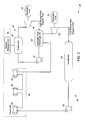
FIG. 1 is a diagrammatical representation of a rankine cycle system having a variable speed expander in accordance with an exemplary embodiment of the present invention, -
FIG. 2 is a diagrammatical representation of a cascaded rankine cycle system having at least one variable speed expander in accordance with an exemplary embodiment of the present invention, -
FIG. 3 is a diagrammatical representation of an expander system in accordance with an exemplary embodiment of the present invention, -
FIG. 4 is a diagrammatical representation of an expander system in accordance with an exemplary embodiment of the present invention, and -
FIG. 5 is a diagrammatical representation of an expander system in accordance with an exemplary embodiment of the present invention. - In accordance with exemplary embodiments of the present invention, a rankine cycle system is disclosed. The rankine cycle system includes an evaporator coupled to a heat source and configured to circulate a working fluid in heat exchange relationship with a hot fluid from the heat source so as to heat the working fluid and vaporize the working fluid. An expander is coupled to the evaporator and configured to expand the vaporized working fluid from the evaporator. The exemplary expander is operable at variable speed. A condenser is coupled to the expander and configured to condense the vaporized working fluid from the expander. A pump is coupled to the condenser and configured to feed the condensed working fluid from the condenser to the evaporator. In accordance with a specific embodiment of the present invention, a waste heat recovery system including at least two integrated rankine cycle systems having an expander operable at variable speed is disclosed.
- Referring to
FIG. 1 , arankine cycle system 10 is illustrated in accordance with an exemplary embodiment of the present invention. A working fluid is circulated through therankine cycle system 10. In one embodiment, the working fluid may be an organic working fluid and may include cyclohexane, cyclopentane, thiophene, ketones, aromatics, propane, butane, pentafluoro-propane, pentafluoro-butane, pentafluoro-polyether, or combinations thereof. It should be noted herein that list of working fluids are not inclusive and other working fluids applicable to rankine cycles are also envisaged. Therankine cycle system 10 includes anevaporator 12 coupled to aheat source 14, for example an exhaust unit of a heat generation system (for example, an engine). Theevaporator 12 receives heat from a hot fluid generated from theheat source 14 and generates a working fluid vapor. The vaporized working fluid is passed through anexpander 16 to drive agenerator 18 configured to generate power. Theexpander 16 may be at least one radial type expander, axial type expander, high temperature screw type or impulse type expander, positive displacement type expander. After expanding through thefirst expander 16, the working fluid vapor at a relatively lower pressure and lower temperature is passed through acondenser 20. The working fluid vapor is condensed into a liquid, which is then pumped via apump 22 to theevaporator 12. The cycle may then be repeated. - In the illustrated embodiment, the
expander 16 is directly coupled to thegenerator 18 configured to generate power. The speed of theexpander 16 is operable at variable speed. Theexemplary generator 18 is an asynchronous generator. In such generators, if the revolutions per minute are held constant, the frequency varies depending on the power level. The peaks of the sinusoidal waveform have no fixed relationship with a rotor position. The magnetic field of a rotor is generated via a stator through electromagnetic induction. - The exemplary
rankine cycle system 10 does not have constraints that it can operate only at design state points (pressures, mass flows and temperatures). Theexpander 16 and thegenerator 18 are operable at variable speeds during partial load conditions or off design operating conditions. Hence therankine cycle system 10 can be operated at a wide range of state points. As a result, the cycle efficiency is increased and component operation limits are not exceeded. - Referring to
FIG. 2 , a wasteheat recovery system 24 is illustrated in accordance with an exemplary embodiment of the present invention. The illustrated wasteheat recovery system 24 includes a first organic rankine cycle system 26 (top cycle) and a second organic rankine cycle system 28 (bottom cycle). A first organic working fluid is circulated through the first organicrankine cycle system 26. The first organic working fluid may include cyclohexane, cyclopentane, thiophene, ketones, aromatics, or combinations thereof. The first organicrankine cycle system 26 includes anevaporator 30 coupled to afirst heat source 32, for example an exhaust unit of a heat generation system 34 (for example, an engine). Theevaporator 30 receives heat from the exhaust gas generated from thefirst heat source 32 and generates a first organic working fluid vapor. The first organic working fluid vapor is passed through afirst expander 36 to drive afirst generator 38. The first expander may be radial type expander, axial type expander, impulse type expander, or high temperature screw type expander, positive displacement type expander. After passing through thefirst expander 36, the first organic working fluid vapor at a relatively lower pressure and lower temperature is passed through a cascadedheat exchange unit 40. The first organic working fluid vapor is condensed into a liquid, which is then pumped via apump 42 to theevaporator 30. The cycle may then be repeated. - The cascaded
heat exchange unit 40 is used both as a condenser for the first organicrankine cycle system 26 and as evaporator for the second organicrankine cycle system 28. A second organic working fluid is circulated through the second organicrankine cycle system 28. The second organic working fluid may include propane, butane, pentafluoro-propane, pentafluoro-butane, pentafluoro-polyether, oil, or combinations thereof. It should be noted herein that list of first and second organic working fluids are not inclusive and other organic working fluids applicable to organic rankine cycles are also envisaged. Cascadedheat exchange unit 40 may be coupled to any one or more of a plurality of second heat sources such as anintercooler 44, anoil heat exchanger 46, and a cooling waterjacket heat exchanger 48. Such second heat sources are also typically coupled to the engine. It should be noted herein that the second heat source includes a lower temperature heat source than the first heat source. It should be noted that in other exemplary embodiments, first and second heat sources may include other multiple low-grade heat sources such as gas turbines with intercoolers. The cascadedheat exchange unit 40 receives heat from the first organic working fluid and generates a second organic working fluid vapor. The second organic working fluid vapor is passed through asecond expander 50 to drive asecond generator 52. In certain other exemplary embodiments, thesecond expander 50 may be a radial type expander, an axial type expander, high temperature screw type or an impulse type expander, positive displacement type expander. - In an exemplary embodiment, neither of the first and second organic working fluids are expanded below the atmospheric pressure, and the boiling point temperature of the first organic working fluid is below the average temperature of the second heat source. After passing through the
second expander 50, the second organic working fluid vapor at lower pressure and lower temperature is passed through acondenser 54. The second organic working fluid vapor is condensed into a liquid, which is then pumped via apump 56 to the second heat sources. The cycle may then be repeated. It should be noted herein that the number of second heat sources such as intercoolers, oil heat exchangers, jacket heat exchangers, evaporators and their relative positions explained in greater detail inU.S. Patent Application 11/770,895 is incorporated herein by reference. - In the illustrated embodiment, the
expanders generators expanders exemplary generators - Referring to
FIG. 3 , anexemplary expander system 58 for a rankine cycle system is disclosed. In the illustrated embodiment, thesystem 58 includes amulti-stage expander 60 having an expanderfirst stage 62 and an expandersecond stage 64. In certain other embodiments, the multi-stage expander may include more than two stages. In a more specific embodiment, theexpander 60 is a multi-screw expander. The expanderfirst stage 62 and the expandersecond stage 64 are coupled to agenerator 66 via agearbox 68. Thegenerator 66 is an asynchronous generator. In a specific embodiment, a gear ratio of thegearbox 68 may be varied to vary the speed of theexpander 60. In the illustrated embodiment, the vaporized working fluid is passed through the expanderfirst stage 62 and then through the expandersecond stage 64 to drive thegenerator 66 configured to generate power. In other words, the vaporized working fluid is expanded successively through thestages stages - Referring to
FIG. 4 , anexemplary expander system 70 for a rankine cycle system is disclosed. In the illustrated embodiment, thesystem 70 includes amulti-stage expander 72 having an expanderfirst stage 74 and an expandersecond stage 76. In one embodiment, theexpander 72 is a multi-screw expander. The expanderfirst stage 74 and the expandersecond stage 76 are coupled directly to agenerator 78. Thegenerator 78 is an asynchronous generator. In the illustrated embodiment, the vaporized working fluid is passed through the expanderfirst stage 74 and then through the expandersecond stage 76 to drive thegenerator 78 configured to generate power. After expanding through thestages - In the illustrated embodiment, the
asynchronous generator 78 is operable at variable speed so as to control the speed of theexpander 72. Theexemplary generator 78 is coupled to afrequency inverter 80 configured to vary the speed of thegenerator 78. Thefrequency inverter 80 controls the rotational speed of thegenerator 78 by controlling the frequency of the electrical power of thegenerator 78. - Referring to
FIG. 5 , anexemplary expander system 82 for a rankine cycle system is disclosed. In the illustrated embodiment, thesystem 82 includes amulti-stage expander 84 having an expanderfirst stage 86 and an expander second stage 88. In one embodiment, theexpander 84 is a multi-screw expander. The expanderfirst stage 86 and the expander second stage 88 are coupled respectively togenerators generators first stage 86 and then through the expander second stage 88 to drive thegenerators stages 86, 88 the working fluid vapor at a relatively lower pressure and lower temperature is passed through a condenser. Similar to the previous embodiments, theexpander 84 is operable at variable speed. - The exemplary expander discussed above with reference to
FIGS. 1-5 , are adaptable to full and partial load conditions of organic rankine cycles. Further the exemplary expander is also robust to changes in inlet and outlet flow conditions of organic rankine cycles. It should be noted herein that embodiments discussed with reference toFIGS. 3-5 is applicable to therankine cycle system 10 ofFIG. 1 , the first organic rankine cycle system 26 (top cycle), or a second organic rankine cycle system 28 (bottom cycle), or combinations thereof ofFIG. 2 . All such permutations and combinations are envisaged. - While only certain features of the invention have been illustrated and described herein, many modifications and changes will occur to those skilled in the art. It is, therefore, to be understood that the appended claims are intended to cover all such modifications and changes as fall within the true spirit of the invention.
- Various aspects and embodiments of the present invention are defined by the following numbered clauses:
- 1. A rankine cycle system, comprising:
- an evaporator coupled to a heat source and configured to circulate a working fluid in heat exchange relationship with a hot fluid from the heat source so as to heat the working fluid and vaporize the working fluid;
- an expander coupled to the evaporator and configured to expand the vaporized working fluid from the evaporator; wherein the expander is operable at variable speed;
- a condenser coupled to the expander and configured to condense the vaporized working fluid from the expander;
- a pump coupled to the condenser and configured to feed the condensed working fluid from the condenser to the evaporator.
- 2. The system of clause 1, wherein the working fluid comprises cyclohexane, cyclopentane, thiophene, ketones, aromatics, propane, butane, pentafluoro-propane, pentafluoro-butane, pentafluoro-polyether, or combinations thereof.
- 3. The system of any preceding clause, wherein the expander comprises at least one radial type expander, axial type expander, high temperature screw type or impulse type expander, positive displacement type expander.
- 4. The system of any preceding clause, wherein the expander comprises a multi-stage screw expander.
- 5. The system of any preceding clause, wherein the expander is a multi-screw expander.
- 6. The system of any preceding clause, wherein the expander is directly coupled to at least one asynchronous generator configured to generate power.
- 7. The system of any preceding clause, wherein the asynchronous generator is operable at variable speed to vary the speed of the expander.
- 8. The system of any preceding clause, further comprising a frequency inverter configured to vary the speed of the asynchronous generator.
- 9. The system of any preceding clause, wherein the expander is coupled via a gearbox to at least one asynchronous generator configured to generate power.
- 10. The system of any preceding clause, wherein a gear ratio of the gearbox is variable to vary the speed of the expander.
- 11. A waste heat recovery system including at least two integrated rankine cycle systems, the recovery system comprising:
- a heat generation system comprising at least two separate heat sources having different temperatures;
- a first rankine cycle system comprising a first expander, wherein the first rankine cycle system is coupled to a first heat source among the at least two separate heat sources and configured to circulate a first working fluid; wherein the first rankine system is configured to remove heat from the first heat source; wherein the first expander is operable at variable speed;
- a second rankine cycle system comprising a second expander; wherein the second rankine cycle system is coupled to at least one second heat source among the at least two separate heat sources and configured to circulate a second working fluid, the at least one second heat source comprising a lower temperature heat source than the first heat source, wherein the second rankine cycle system is configured to remove heat from the at least one second heat source; wherein the second expander is operable at variable speed; and
- a cascaded heat exchange unit, wherein the first and second working fluids are circulatable in heat exchange relationship through the cascaded heat exchange unit for condensation of the first working fluid in the first rankine cycle system and evaporation of the second working fluid in the second rankine cycle system.
- 12. The system of any preceding clause, wherein the first working fluid comprises cyclohexane, cyclopentane, thiophene, ketones, aromatics, or combinations thereof.
- 13. The system of any preceding clause, wherein the first expander comprises at least one radial type expander, axial type expander, high temperature screw type or impulse type expander, positive displacement type expander.
- 14. The system of any preceding clause, wherein the first expander comprises a multi-stage screw expander.
- 15. The system of any preceding clause, wherein the first expander is a multi-screw expander.
- 16. The system of any preceding clause, wherein the first expander is directly coupled to at least one asynchronous generator configured to generate power.
- 17. The system of any preceding clause, further comprising a frequency inverter configured to vary the speed of the asynchronous generator.
- 18. The system of any preceding clause, wherein the expander is coupled via a gearbox to at least one asynchronous generator configured to generate power.
- 19. The system of any preceding clause, wherein a gear ratio of the gearbox is variable to vary the speed of the expander.
- 20. The system of any preceding clause, wherein the second organic working fluid comprises propane, butane, pentafluoro-propane, pentafluoro-butane, pentafluoro-polyether, oil, or combinations thereof.
- 21. The system of any preceding clause, wherein the second expander comprises at least one radial type expander, axial type expander, high temperature screw type or impulse type expander, positive displacement type expander.
- 22. The system of any preceding clause, wherein the second expander comprises a multi-stage screw expander.
- 23. The system of any preceding clause, wherein the second expander is directly coupled to at least one asynchronous generator configured to generate power.
- 24. The system of any preceding clause, further comprising a frequency inverter configured to vary the speed of the asynchronous generator.
- 25. The system of any preceding clause, wherein the second expander is coupled via a gearbox to at least one asynchronous generator configured to generate power.
- 26. The system of any preceding clause, wherein a gear ratio of the gearbox is variable to vary the speed of the expander.
Claims (10)
- A rankine cycle system (10), comprising:an evaporator (12) coupled to a heat source (14) and configured to circulate a working fluid in heat exchange relationship with a hot fluid from the heat source (14) so as to heat the working fluid and vaporize the working fluid;an expander (16) coupled to the evaporator (12) and configured to expand the vaporized working fluid from the evaporator (12); wherein the expander (16) is operable at variable speed;a condenser (54) coupled to the expander (16) and configured to condense the vaporized working fluid from the expander (16);a pump (22) coupled to the condenser (54) and configured to feed the condensed working fluid from the condenser (54) to the evaporator (12).
- The system (10) of claim 1, wherein the expander (16) comprises at least one radial type expander, axial type expander, high temperature screw type or impulse type expander, positive displacement type expander.
- The system (10) of any preceding claim, wherein the expander (16) comprises a multi-stage screw expander.
- The system (10) of any preceding claim, wherein the expander (16) is a multi-screw expander.
- The system (10) of any preceding claim, wherein the expander (16) is directly coupled to at least one asynchronous generator (78) configured to generate power.
- The system (10) of any preceding claim, wherein the asynchronous generator (78) is operable at variable speed to vary the speed of the expander (16).
- The system (10) of claim 5 or claim 6, further comprising a frequency inverter (80) configured to vary the speed of the asynchronous generator (78).
- The system (10) of any preceding claim, wherein the expander (16) is coupled via a gearbox (68) to at least one asynchronous generator (78) configured to generate power.
- The system (10) of claim 8, wherein a gear ratio of the gearbox (68) is variable to vary the speed of the expander (16).
- A waste heat recovery system (24) including at least two integrated rankine cycle systems (26, 28), the recovery system (24) comprising:a heat generation system (34) comprising at least two separate heat sources (32, 44, 46, 48) having different temperatures;a first rankine cycle system (26) comprising a first expander (36), wherein the first rankine cycle system (26) is coupled to a first heat source (32) among the at least two separate heat sources (32, 44, 46, 48) and configured to circulate a first working fluid; wherein the first rankine system (26) is configured to remove heat from the first heat source (32); wherein the first expander (36) is operable at variable speed;a second rankine cycle system (28) comprising a second expander (50); wherein the second rankine cycle system (28) is coupled to at least one second heat source (44, 46, 48) among the at least two separate heat sources (32, 44, 46, 48) and configured to circulate a second working fluid, the at least one second heat source (44, 46, 48) comprising a lower temperature heat source than the first heat source (32), wherein the second rankine cycle system (28) is configured to remove heat from the at least one second heat source (32, 44, 46, 48); wherein the second expander (50) is operable at variable speed; anda cascaded heat exchange unit (40), wherein the first and second working fluids are circulatable in heat exchange relationship through the cascaded heat exchange unit (40) for condensation of the first working fluid in the first rankine cycle system (26) and evaporation of the second working fluid in the second rankine cycle system (28).
Applications Claiming Priority (1)
| Application Number | Priority Date | Filing Date | Title |
|---|---|---|---|
| US12/577,893 US20110083437A1 (en) | 2009-10-13 | 2009-10-13 | Rankine cycle system |
Publications (2)
| Publication Number | Publication Date |
|---|---|
| EP2360354A2 true EP2360354A2 (en) | 2011-08-24 |
| EP2360354A3 EP2360354A3 (en) | 2012-06-27 |
Family
ID=43853743
Family Applications (1)
| Application Number | Title | Priority Date | Filing Date |
|---|---|---|---|
| EP10186737A Withdrawn EP2360354A3 (en) | 2009-10-13 | 2010-10-06 | Rankine Cycle System |
Country Status (2)
| Country | Link |
|---|---|
| US (1) | US20110083437A1 (en) |
| EP (1) | EP2360354A3 (en) |
Cited By (2)
| Publication number | Priority date | Publication date | Assignee | Title |
|---|---|---|---|---|
| WO2012085262A1 (en) * | 2010-12-24 | 2012-06-28 | Robert Bosch Gmbh | Waste heat recovery installation |
| WO2014146007A1 (en) * | 2013-03-15 | 2014-09-18 | Electratherm, Inc. | Apparatus, systems, and methods for low grade waste heat management |
Families Citing this family (21)
| Publication number | Priority date | Publication date | Assignee | Title |
|---|---|---|---|---|
| US8236093B2 (en) * | 2009-09-16 | 2012-08-07 | Bha Group, Inc. | Power plant emissions control using integrated organic rankine cycle |
| US20110072819A1 (en) * | 2009-09-28 | 2011-03-31 | General Electric Company | Heat recovery system based on the use of a stabilized organic rankine fluid, and related processes and devices |
| US9140145B1 (en) * | 2011-08-11 | 2015-09-22 | Sandia Corporation | PH adjustment of power plant cooling water with flue gas/fly ash |
| CN102434236A (en) * | 2011-11-17 | 2012-05-02 | 重庆川然节能技术有限公司 | Screw expansion/centripetal turbine low-parameter waste heat combined generator set |
| DE102012205159A1 (en) * | 2012-03-29 | 2013-10-02 | Siemens Aktiengesellschaft | Turbine system with three connected to a central transmission turbines, turbine plant and method for operating a work machine |
| CN102644489A (en) * | 2012-04-27 | 2012-08-22 | 北京亿玮坤节能科技有限公司 | Cycle power generator unit |
| US10060299B2 (en) * | 2013-09-19 | 2018-08-28 | Husham Al Ghizzy | Thermo-elevation plant and method |
| DE102014206033A1 (en) * | 2014-03-31 | 2015-10-01 | Mtu Friedrichshafen Gmbh | Method for operating a system for a thermodynamic cycle, control device for a system for a thermodynamic cycle, system, and arrangement of an internal combustion engine and a system |
| CN107849945B (en) * | 2015-04-24 | 2020-02-14 | 诺沃皮尼奥内技术股份有限公司 | Compressor driven by ORC waste heat recovery unit and control method |
| US9725652B2 (en) | 2015-08-24 | 2017-08-08 | Saudi Arabian Oil Company | Delayed coking plant combined heating and power generation |
| US10113448B2 (en) | 2015-08-24 | 2018-10-30 | Saudi Arabian Oil Company | Organic Rankine cycle based conversion of gas processing plant waste heat into power |
| US9803506B2 (en) | 2015-08-24 | 2017-10-31 | Saudi Arabian Oil Company | Power generation from waste heat in integrated crude oil hydrocracking and aromatics facilities |
| US9803507B2 (en) | 2015-08-24 | 2017-10-31 | Saudi Arabian Oil Company | Power generation using independent dual organic Rankine cycles from waste heat systems in diesel hydrotreating-hydrocracking and continuous-catalytic-cracking-aromatics facilities |
| US9803505B2 (en) | 2015-08-24 | 2017-10-31 | Saudi Arabian Oil Company | Power generation from waste heat in integrated aromatics and naphtha block facilities |
| US9745871B2 (en) | 2015-08-24 | 2017-08-29 | Saudi Arabian Oil Company | Kalina cycle based conversion of gas processing plant waste heat into power |
| US9803509B2 (en) | 2015-08-24 | 2017-10-31 | Saudi Arabian Oil Company | Power generation from waste heat in integrated crude oil refining and aromatics facilities |
| US9803508B2 (en) | 2015-08-24 | 2017-10-31 | Saudi Arabian Oil Company | Power generation from waste heat in integrated crude oil diesel hydrotreating and aromatics facilities |
| US9803513B2 (en) | 2015-08-24 | 2017-10-31 | Saudi Arabian Oil Company | Power generation from waste heat in integrated aromatics, crude distillation, and naphtha block facilities |
| US9803511B2 (en) | 2015-08-24 | 2017-10-31 | Saudi Arabian Oil Company | Power generation using independent dual organic rankine cycles from waste heat systems in diesel hydrotreating-hydrocracking and atmospheric distillation-naphtha hydrotreating-aromatics facilities |
| US20210017883A1 (en) * | 2017-12-18 | 2021-01-21 | Exergy International S.R.L. | Process, plant and thermodynamic cycle for production of power from variable temperature heat sources |
| CN113137286A (en) * | 2020-01-16 | 2021-07-20 | 勤益科技大学 | Organic rankine cycle system with multiple expanders |
Family Cites Families (11)
| Publication number | Priority date | Publication date | Assignee | Title |
|---|---|---|---|---|
| US4525633A (en) * | 1982-09-28 | 1985-06-25 | Grumman Aerospace Corporation | Wind turbine maximum power tracking device |
| US6981378B2 (en) * | 2001-02-12 | 2006-01-03 | Ormat Technologies Inc. | Method of and apparatus for producing uninterruptible power |
| US20030213246A1 (en) * | 2002-05-15 | 2003-11-20 | Coll John Gordon | Process and device for controlling the thermal and electrical output of integrated micro combined heat and power generation systems |
| US8061139B2 (en) * | 2002-05-22 | 2011-11-22 | Ormat Technologies, Inc. | Integrated engine generator rankine cycle power system |
| US6857268B2 (en) * | 2002-07-22 | 2005-02-22 | Wow Energy, Inc. | Cascading closed loop cycle (CCLC) |
| CN101248253B (en) * | 2005-03-29 | 2010-12-29 | Utc电力公司 | Cascade Organic Rankine Cycle Using Waste Heat |
| US7841306B2 (en) * | 2007-04-16 | 2010-11-30 | Calnetix Power Solutions, Inc. | Recovering heat energy |
| US8561405B2 (en) * | 2007-06-29 | 2013-10-22 | General Electric Company | System and method for recovering waste heat |
| EP2014880A1 (en) * | 2007-07-09 | 2009-01-14 | Universiteit Gent | An improved combined heat power system |
| DE202007016668U1 (en) * | 2007-12-04 | 2008-02-28 | GMK-Gesellschaft für Motoren und Kraftanlagen mbH | Power generation plant according to the ORC principle |
| US20090277400A1 (en) * | 2008-05-06 | 2009-11-12 | Ronald David Conry | Rankine cycle heat recovery methods and devices |
-
2009
- 2009-10-13 US US12/577,893 patent/US20110083437A1/en not_active Abandoned
-
2010
- 2010-10-06 EP EP10186737A patent/EP2360354A3/en not_active Withdrawn
Cited By (3)
| Publication number | Priority date | Publication date | Assignee | Title |
|---|---|---|---|---|
| WO2012085262A1 (en) * | 2010-12-24 | 2012-06-28 | Robert Bosch Gmbh | Waste heat recovery installation |
| WO2014146007A1 (en) * | 2013-03-15 | 2014-09-18 | Electratherm, Inc. | Apparatus, systems, and methods for low grade waste heat management |
| US9243520B2 (en) | 2013-03-15 | 2016-01-26 | Electratherm, Inc. | Apparatus, systems, and methods for low grade waste heat management |
Also Published As
| Publication number | Publication date |
|---|---|
| US20110083437A1 (en) | 2011-04-14 |
| EP2360354A3 (en) | 2012-06-27 |
Similar Documents
| Publication | Publication Date | Title |
|---|---|---|
| EP2360354A2 (en) | Rankine Cycle System | |
| EP2203630B1 (en) | System for recovering waste heat | |
| EP2345799A2 (en) | Optimized system for recovering waste heat | |
| RU2688342C2 (en) | System operating as per rankine cycle, and corresponding method | |
| EP2410153A2 (en) | A hybrid power generation system and a method thereof | |
| CN102695860B (en) | For reclaiming compound closed-loop heat cycle system and the method thereof of used heat | |
| US20100242476A1 (en) | Combined heat and power cycle system | |
| US20100122534A1 (en) | Two-phase expansion system and method for energy recovery | |
| US20090151356A1 (en) | System and method for controlling an expansion system | |
| EP2423474A2 (en) | Tri-generation system using cascading organic rankine cycle | |
| EP2834477B1 (en) | System and method for recovery of waste heat from dual heat sources | |
| KR20060055430A (en) | Dual Use Radial Turbo Machine | |
| EP2954177A1 (en) | Improved organic rankine cycle decompression heat engine | |
| EP2467584A2 (en) | System for recovering waste heat | |
| CN102383939B (en) | Multi-working-medium turbine engine | |
| Wang et al. | Thermodynamic evaluation of an ORC system with a low pressure saturated steam heat source | |
| EP2211028B1 (en) | System for converting waste heat from a waste heat source | |
| EP3420201B1 (en) | Waste heat recovery cascade cycle and method | |
| Okita et al. | Steam turbines for solar thermal and other renewable energies | |
| van den Broek et al. | Organic Rankine Cycle systems: A techno-economic overview | |
| Ast et al. | Experimental investigation of an organic Rankine cycle prototype plant being developed to boost the electric output of gas engine power stations | |
| Çengal et al. | Vapor and combined power cycles | |
| EP3167158A1 (en) | Turbine and method for expanding an operating fluid with high isentropic enthalpy jump | |
| Alshammari | Energy and Exergy Analyses of Automotive Organic Rankine Cycles | |
| Okita et al. | 1Toshiba Corporation, Yokohama, Japan, 2IHI Corporation, Yokohama, Japan, 3Kobe Steel, Ltd., Kobe, Japan |
Legal Events
| Date | Code | Title | Description |
|---|---|---|---|
| PUAI | Public reference made under article 153(3) epc to a published international application that has entered the european phase |
Free format text: ORIGINAL CODE: 0009012 |
|
| AK | Designated contracting states |
Kind code of ref document: A2 Designated state(s): AL AT BE BG CH CY CZ DE DK EE ES FI FR GB GR HR HU IE IS IT LI LT LU LV MC MK MT NL NO PL PT RO RS SE SI SK SM TR |
|
| AX | Request for extension of the european patent |
Extension state: BA ME |
|
| PUAL | Search report despatched |
Free format text: ORIGINAL CODE: 0009013 |
|
| AK | Designated contracting states |
Kind code of ref document: A3 Designated state(s): AL AT BE BG CH CY CZ DE DK EE ES FI FR GB GR HR HU IE IS IT LI LT LU LV MC MK MT NL NO PL PT RO RS SE SI SK SM TR |
|
| AX | Request for extension of the european patent |
Extension state: BA ME |
|
| RIC1 | Information provided on ipc code assigned before grant |
Ipc: F01K 13/02 20060101ALI20120523BHEP Ipc: F01K 7/02 20060101AFI20120523BHEP Ipc: F01K 25/08 20060101ALI20120523BHEP |
|
| 17P | Request for examination filed |
Effective date: 20130102 |
|
| STAA | Information on the status of an ep patent application or granted ep patent |
Free format text: STATUS: THE APPLICATION IS DEEMED TO BE WITHDRAWN |
|
| 18D | Application deemed to be withdrawn |
Effective date: 20140501 |