EP2360124B1 - Gob scoop for a glassware manufacturing machine - Google Patents
Gob scoop for a glassware manufacturing machine Download PDFInfo
- Publication number
- EP2360124B1 EP2360124B1 EP11153753.6A EP11153753A EP2360124B1 EP 2360124 B1 EP2360124 B1 EP 2360124B1 EP 11153753 A EP11153753 A EP 11153753A EP 2360124 B1 EP2360124 B1 EP 2360124B1
- Authority
- EP
- European Patent Office
- Prior art keywords
- scoop
- gobs
- optimized
- glass
- gob
- Prior art date
- Legal status (The legal status is an assumption and is not a legal conclusion. Google has not performed a legal analysis and makes no representation as to the accuracy of the status listed.)
- Not-in-force
Links
Images



Classifications
-
- C—CHEMISTRY; METALLURGY
- C03—GLASS; MINERAL OR SLAG WOOL
- C03B—MANUFACTURE, SHAPING, OR SUPPLEMENTARY PROCESSES
- C03B7/00—Distributors for the molten glass; Means for taking-off charges of molten glass; Producing the gob, e.g. controlling the gob shape, weight or delivery tact
- C03B7/14—Transferring molten glass or gobs to glass blowing or pressing machines
- C03B7/16—Transferring molten glass or gobs to glass blowing or pressing machines using deflector chutes
Definitions
- the present invention relates generally to apparatus for delivering molten gobs of glass supplied by a shearing mechanism from a stream of molten glass to the parison molds of an Individual Section (IS) machine for making glass containers, and more particularly to a scoop for receiving the glass gobs formed by the shearing mechanism and providing an optimal trajectory while ensuring that glass gobs passing therethrough will have an optimal and uniform gob shape.
- IS Individual Section
- Glass containers are made in a manufacturing process that has three distinct operations, namely the batch house, the hot end, and the cold end.
- the batch house is where the raw materials for glass (which are typically sand, soda ash, limestone, feldspar, cullet (crushed, recycled glass), and other raw materials) are prepared and mixed into batches.
- the hot end melts the batched materials into molten glass, distributes discrete segments of molten glass referred to in the industry as glass "gobs" to molding apparatus where they are molded into glass containers, and anneals the glass containers to prevent them from being weakened due to stresses caused by uneven cooling.
- the cold end inspects the glass containers to ensure that they are of acceptable quality.
- the molding portion of the hot end of the manufacturing process is performed in an Individual Section or IS forming machine, which contains between five and twenty identical sections, each of which is capable of making one, two, three, or four containers simultaneously.
- the hot end begins with a furnace, in which the batched materials are melted into molten glass, and from which streams of molten glass flow through a feeder bowl to multiple outlets. Since each section of an IS machine has one, two, three, or four sets of molding apparatus which will operate simultaneously, one, two, three, or four outlets from the furnace will simultaneously supply streams of molten glass to these respective sets of molding apparatus.
- Each of the streams of molten glass is cut with a shearing mechanism into uniform segments of glass called gobs, which fall by gravity and are guided through scoops, troughs, and deflectors into their respective blank (or parison) molds in the section of the IS machine.
- a pre-container referred to as a parison is formed, either by using a metal plunger to push the glass gob into the blank mold, or by blowing the glass gob out from below into the blank mold.
- the parison is then inverted and it is transferred to a second or blow mold, where the parison is blown out into the shape of the finished glass container.
- the blown parison is then cooled in the blow mold to the point where it is sufficiently rigid to be gripped and removed from the blow station.
- the general focus of the present invention is on the apparatus that distributes a glass gob to the molding apparatus in a section, which apparatus typically includes a scoop, a trough, and a deflector.
- a scoop receives a vertically falling glass gob at a location under the shearing mechanism and is curved to redirect the trajectory of the glass gob from a vertical drop at a first or inlet end of the scoop to an angular trajectory at a second or outlet end of the scoop.
- the glass gob From the second or outlet end of the scoop, the glass gob enters a first or upper end of an upwardly facing downwardly sloping generally straight trough that is generally aligned with the second or outlet end of the scoop and exits a second or lower end of the trough.
- the upper end of the scoop is wider than glass gobs entering the scoop to ensure that the glass gobs will be captured within the scoop.
- the glass gob From the second or lower end of the trough, the glass gob enters the upper end of a downwardly facing curved deflector and is redirected to a vertical drop at a second or lower end of the deflector, from which the glass gob is directed into the blank mold.
- the upper end of the deflector is generally aligned with the second or outlet end of the trough.
- the trough has a generally U-shaped cross-sectional configuration that is open on its upwardly facing side, while the deflector has a generally inverted U-shaped cross-sectional configuration that is open in its downwardly facing side.
- the specific focus of the present invention is on the first element of this glass gob distributing apparatus, the scoop. It will be appreciated by those skilled in the art that delivering a good glass gob to the blank mold is of great importance and that the design of the scoop has a direct impact on the shape of the glass gob as it transits the scoop. A good glass gob should have a uniform shape and should be the correct length for the blank mold. Further, in order to get the glass gob to load deep into the blank mold, a high gob velocity is required as well as a properly shaped glass gob. It is not possible to make a good glass container from a poor quality or slow glass gob.
- a glass gob is formed from molten glass dropping from an orifice in a gob feeder in a glass stream. This glass stream falls downwardly due to the forces of gravity, and is cut into uniform glass gobs by a shear mechanism. Since the molten glass flowing downwardly from the orifice in the gob feeder is very fluid, as the glass stream drops through gravity, it begins to break away in the middle, below the point at which the glass gob is cut by the shear mechanism.
- the shape of the glass gob is also influenced by an oscillating motion of a "needle" located in the gob feeder that tends to push molten glass out of the orifice in the gob feeder as it moves downward and tends to draw the glass back up into the orifice as it moves upward. This produces a glass gob having enlarged upper and lower portions with a narrowed intermediate portion, a shape which is referred to in the industry as a "dog-bone" shape.
- the glass gobs do not recover from variations in the shape of the glass gobs as they are supplied to this delivery system. While popular belief in the past has been that they can recover their shape in this delivery system to some degree, the inventors have determined that this is not the case. However, the inventors have determined that any shaping of glass gobs that is done in this delivery system will affect the shape of the glass gobs delivered to the blank mold.
- the present invention is directed to a scoop for conveying gobs of molten glass generally of the type disclosed in US-2002/046,575A1 and as defined in the preamble of claim 1.
- this US-A1 is concerned with configuring the scoop to accommodate a wide range of gob sizes, and to maintaining the gobs out of contact with the bottom of the scoop to avoid contact with any liquid coolant that may be flowing through the scoop along the bottom thereof.
- a scoop as defined in the characterizing clause of claim 1.
- the invention also provides an Individual Section machine as defined in claim 16 and a method for conveying gobs of molten glass as defined in claim 17.
- the optimized scoop embodying the present invention should be capable of a construction which is both durable and long lasting, and it should also require little or no maintenance to be provided by the user throughout its operating lifetime. In order to enhance the market appeal of the optimized scoop embodying the present invention, it should also be of inexpensive construction to thereby afford it the broadest possible market. Finally, it is also an objective that the aforesaid advantages are capable of being achieved without incurring any substantial relative disadvantage.
- the disadvantages and limitations of the background art discussed above are alleviated or overcome by the scoop embodying the present invention.
- Two fundamental changes are made to the configuration of a scoop to optimize the scoop to transit glass gobs therethrough while giving the glass gobs an optimized shape without substantially sacrificing glass gob velocity.
- the first change is to provide a gradual taper to the optimized scoop to facilitate shaping of the glass gob into a more cylindrical configuration as it transits the optimized scoop.
- the second change is to provide an optimum glass gob trajectory within the optimized scoop to increase the velocity of the glass gob as it transits the optimized scoop.
- the focus of the new optimized scoop is to provide glass gobs having an optimal shape without sacrificing glass gob velocity.
- An optimal trajectory for the optimized scoop is selected to increase the glass gob speed over that of existing scoops, while elongating the glass gob only slightly.
- the cross-sectional configuration of the optimized scoop is gradually tapered and has a lower end that is slightly smaller than the largest diameter portion of glass gobs delivered to the optimized scoop. While existing scoops have utilized a flared opening at the upper end to provide a funneling effect to help ensure that glass gobs are captured by the scoop, they have not been tapered in the manner utilized by the optimized scoop embodying the present invention, which is tapered to cause the glass gob to be slightly extruded, thus obtaining a desirable shape.
- This cross-section design of the optimized scoop can greatly reduce the variations in glass gobs due to non-uniform glass gobs being provided from the gob feeder to the scoop or due to transit (wandering) of the glass gobs as they pass through previously known scoop designs.
- With the improved cross-sectional configuration of the optimized scoop it is possible to simultaneously improve glass gob shape and reduce variations in the glass gobs delivered to the trough, while reducing glass gob speed only marginally.
- Another effect of the optimized scoop is the elimination of dog-bone configurations of the glass gobs.
- the optimized scoop is able to minimize this velocity reduction and may actually marginally increase the velocity of glass gobs (relative to previously known scoop designs) transiting the optimized scoop by utilizing a unique scoop trajectory design.
- the optimized scoop embodying the present invention uses Bezier curves to define the trajectory of the optimized scoop. (Bezier curves are well known, and are curved lines that are defined by mathematical equations.)
- Bezier parameterization produces generally well behaved optimized scoop profiles that successfully avoid discontinuities and reversals in curvature.
- the use of Bezier curves also allows for the creation of unique optimized scoop profiles very quickly.
- the optimized scoop preferably has a trajectories that is continuous, monotonically decreasing (no local minima), and has no sign changes in curvature, which requirements are all fulfilled by Bezier parameterization using control points.
- By modifying the control points of Bezier curves different configurations of scoops can be created and modeled in order to optimize the scoop. Additionally, by performing a normal force load analysis on the scoop design to maintain smooth increases and decreases in the normal force applied to glass gobs in the scoop that are caused by the curvature, the impact of such normal forces on glass gobs may also be minimized.
- the scoop embodying the present invention improves glass gob shape as the glass gobs transit the optimized scoop.
- the improvements in glass gob shape are accomplished in the optimized scoop without any significant decrease in the speed of the glass gobs as they transit the glass gob delivery system.
- the improvements in glass gob shape in the optimized scoop thus enhance glass gob shape to produce a more uniformly cylindrical glass gobs and eliminate the dog-bone shape, while the optimized trajectory of the optimized scoop prevents any significant reduction in the speed of the glass gobs such that they maintain a sufficient exit velocity from the optimized scoop.
- the improvement in glass gob shape is accomplished in the optimized scoop without significantly lengthening the glass gobs.
- the optimized scoop is capable of a construction which is both durable and long lasting, and which will require little or no maintenance to be provided by the user throughout its operating lifetime.
- the optimized scoop is also capable of inexpensive construction to enhance its market appeal and to thereby afford it the broadest possible market.
- the aforesaid advantages and objectives of the optimized scoop are capable of being achieved without incurring any substantial relative disadvantage.
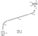
- Fig. 1 is a side view of a generic glass gob delivery system for supplying a glass gob to a parison mold, showing a scoop, a trough, and a deflector;
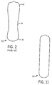
- FIG. 2 is a side view showing the configuration of a glass gob supplied by the scoop of a conventional glass gob delivery system
- FIG. 3 is an isometric view of an optimized scoop embodying the present invention from above and one side of the optimized scoop showing the taper from the top end to the bottom end thereof;
- FIG. 4 is a plan view of the upper end of the optimized scoop illustrated in FIG. 3 , showing the cross-sectional configuration of the optimized scoop at the upper end thereof;
- FIG. 5 is a plan view of the lower end of the optimized scoop illustrated in FIGS. 3 and 4 , showing the cross-sectional configuration of the optimized scoop at the lower end thereof;
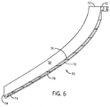
- FIG. 6 is a cross-sectional view of the optimized scoop illustrated in FIGS. 3 and 4 , showing the scoop trajectory that is defined by an optimized Bezier curve;
- FIG. 7 is an exploded bottom plan view showing the fluid cooling passageway located within the optimized scoop illustrated in FIG. 3 prior to the covers being welded to enclose the fluid cooling passageway;
- FIG. 8 is an examplary Bezier curve showing the four control points that define a Bezier curve
- FIG. 9 is a Bezier curve family for optimization of the scoop trajectory of the optimized scoop illustrated in 3 through 7;
- FIG. 10 is a series of plots showing the normal force applied to a glass gob passing through the optimized scoop illustrated in 3 through 5 for several different initial velocities as the glass gob enters the optimized scoop;
- FIG. 11 is a side view showing the configuration of a glass gob supplied by the optimized scoop of the present invention.
- FIG. 1 such a glass gob delivery system is illustrated in schematic form depicting the gravitational delivery of a glass gob 20 from a gob feeder 22 to a parison mold 24. Molten glass exits the gob feeder 22 through an orifice 26 in the bottom of the gob feeder 22, and is cut by a schematically depicted glass gob shear mechanism 28 into a sequence of glass gobs 20.
- the glass gobs 20 fall downwardly into the top end of a scoop 30 that is curved to redirect the glass gobs 20 from a vertical trajectory to a diagonal trajectory, and from the bottom end of the scoop 30 into the upper end of an inclined trough 32. From the lower end of the trough 32, the glass gobs 20 are directed into the top end of a deflector 34 that is curved to redirect the glass gobs 20 from the diagonal trajectory back to a vertical trajectory above the parison mold 24. From the lower end of the deflector 34, the glass gobs 20 fall into the open top side of the parison mold 24.
- a glass gob 20 supplied from the scoop 30 of a conventional glass gob delivery system is shown. It may be seen that the glass gob 20 has an enlarged lower portion 40 as well as an enlarged upper portion 42, with a narrowed intermediate portion 44 located therebetween (the degree of the narrowing at the narrowed intermediate portion 44 of the glass gob 20 has been somewhat exaggerated for purposes of clarity). Since the molten glass flowing out of the orifice 26 in the gob feeder 22 (shown in FIG. 1 ) is very fluid, as the glass gob 20 (as shown in FIG. 1 ) drops through gravity, it begins to break away in the middle, producing the shape shown in FIG.
- This dog-bone shape which is referred to in the industry as a "dog-bone” shape.
- This dog-bone shape which is present at the glass gob shear mechanism, is maintained by glass gobs 20 as they go through a conventional glass gob delivery system, and is one cause of improper gob loading in the parison mold 24 (shown in FIG. 1 ).
- an optimized scoop 50 that is constructed according to the teachings of the present invention is shown.
- the scoop has an upper end 52 and a lower end 54 with a smooth curved portion 56 extending therebetween.
- the optimized scoop 50 will be mounted so that the upper end 52 of the optimized scoop 50 will act as an inlet to the optimized scoop 50, receiving glass gobs (not shown in FIGS. 3 through 7 ) which will fall through the force of gravity vertically into the upper end 52 of the optimized scoop 50.
- the curved portion 56 of the optimized scoop 50 will modify the trajectory of the glass gobs such that they will exit the optimized scoop 50 at the lower end 54 of the optimized scoop 50 at an acute angle with respect to the horizontal that delivers the glass gobs to the trough 32 (shown in FIG. 1 ) with the proper trajectory (which, by way of example, may be approximately thirty degrees, but may vary as desired to accommodate any glass gob delivery system).
- the cross-sectional configuration of the optimized scoop 50 is generally concave (in a two-dimensional sense) and preferably U-shaped, with the bottom of the U-shape preferably being semicircular and the opposite sides 58 and 60 of the optimized scoop 50 above the semicircle preferably being essentially parallel along the curved portion 56 of the optimized scoop 50. It should be noted that these characteristics may vary somewhat without departing from the teachings of the present invention (and thus could potentially include a more V-shaped configuration as well).
- the width of the semicircular bottom of the U-shape preferably varies along the curved portion 56 of the optimized scoop 50 from a maximum width at the upper end 52 of the optimized scoop 50 to a minimum width at the lower end 54 of the optimized scoop 50 to thereby produce a tapered width along the length of the curved portion 56 of the optimized scoop 50.
- the optimized scoop 50 has a mounting flange 62 located at the upper end 52 of the optimized scoop 50, with this mounting flange 62 being used to support the optimized scoop 50 in position in a glass gob delivery system. Located in the mounting flange 62 are a cooling fluid inlet 64 and a cooling fluid outlet 66, which will be used to couple a cooling fluid into and out of the optimized scoop 50. It should be noted that 64 and 66 could also be reversed if so desired.
- cooling channels 68 and 70 Located within the optimized scoop 50 and visibly from the underside thereof (best shown in FIG. 7 ) are two parallel cooling channels 68 and 70 which extend nearly the entire length of the optimized scoop 50.
- the end of the cooling channel 68 near the upper end 52 of the optimized scoop 50 is in fluid communication with the cooling fluid inlet 64, and the end of the cooling channel 70 near the upper end 52 of the optimized scoop 50 is in fluid communication with the cooling fluid outlet 66.
- the cooling channels 68 and 70 are separated by a V-shaped rib 72.
- the cooling channels 68 and 70 are connected together by a channel 74 located near the lower end 54 of the optimized scoop 50.
- a curved panel 76 is placed over the cooling channel 68 and welded in place on the optimized scoop 50 to enclose the cooling channel 68.
- a curved panel 78 is placed over the cooling channel 70 and welded in place on the optimized scoop 50 to enclose the panel 78.
- the optimized scoop 50 may be machined in a single piece (with the exception of the panels 76 and 78) of aluminum, stainless steel, or titanium. While stainless steel and titanium may be used without a coating, aluminum requires a plasma spray coating of a commercially available ceramic material such as those available from Praxair Surface Technologies, Inc. to prevent the glass gobs from sticking to the aluminum surface. Titanium has essentially the same characteristics as stainless steel, but also features significantly reduced weight.
- the width of the semicircular bottom of the U-shape varies linearly along the curved portion 56 of the optimized scoop 50, from the maximum width at the upper end 52 of the optimized scoop 50 to the minimum width at the lower end 54 of the optimized scoop 50.
- the width at the lower end 54 of the optimized scoop 50 is selected to be smaller than the largest diameter of the glass gobs at the enlarged lower portion 40 of the glass gob 20 (shown in FIG. 2 ) and the enlarged upper portion 42 of the glass gob 20 (shown in FIG. 2 ) so that the optimized scoop 50 will act to shape glass gobs passing therethrough.
- the width at the lower end 54 of the optimized scoop 50 is selected to be approximately the same size as the diameter of the narrowed intermediate portion 44 of the glass gob 20, or approximately 30 millimeters.
- the diameter of the lower end of the scoop may thus be, or be approximately, 6.25 percent less, or no more than 6.25 percent less than the diameter of the enlarged upper or lower portion of the gob, which may in turn be, or be approximately, the diameter of the orifice 26 of the gob feeder 22.
- the width at the upper end 52 of the optimized scoop 50 may be approximately 46.5 millimeters.
- the width of the lower end 54 of the optimized scoop 50 must be slightly smaller than the width of at least one of the enlarged lower portion 40 of the glass gob 20 and the enlarged upper portion 42 of the glass gob 20 in order to extrude the glass gobs to more cylindrical configurations without greatly lengthening them.
- the tapering in the optimized scoop 50 and the width of the lower end 54 of the optimized scoop 50 should be selected to optimize the shape of glass gobs passing through the optimized scoop 50 without either unduly lengthening them or significantly reducing the transit speed of glass gobs through the optimized scoop 50.
- the glass gobs may be lengthened as much as approximately twenty percent without incurring any significant disadvantage through so doing.
- Bezier curves are used to represent the trajectory of the optimized scoop 50, as shown in FIG. 8 .
- four control points are used to generate the curvature of the optimized scoop 50 which defines the trajectory of glass gobs passing therethrough.
- Control Point 1 and Control Point 4 are the starting point and the end point of the optimized scoop 50, respectively, which are fixed (to thereby reduce the number of adjustable parameters to eight, two coordinates for each of the two remaining control points).
- the other two control points (Control Point 2 and Control Point 3) may be varied to change the overall shape of the curvature of the optimized scoop 50.
- Control Point 2 Since the glass gobs enter the optimized scoop 50 falling vertically due to gravity, Control Point 2 is along the vertical axis below Control Point 1. Since the trajectory at which glass gobs leave the optimized scoop 50 (for the trough 32 shown in FIG. 1 ) is defined by an acute angle e measured with respect to the horizontal axis, Control Point 3 will be along a line displaced at the acute angle e from the horizontal axis.
- the adjustability of the control points is limited to two parameters.
- the overall shape of the curvature or trajectory of the optimized scoop 50 may be varied.
- the resulting trajectory is always tangent to the line extending between Control Point 1 and Control Point 2 at Control Point 1, and is always tangent to the line extending between Control Point 4 and Control Point 3 at Control Point 4.
- the trajectory will tend to maintain its initial slope and "stick" to the line from Control Point 1 to Control Point 2 longer.
- the trajectory will tend to become approximately tangent to the line from Control Point 4 to Control Point 3 sooner, "sticking" to the line from Control Point 4 to Control Point 3 sooner.
- Control Point 2 and Control Point 3 By appropriately limiting the allowable selection of Control Point 2 and Control Point 3, the curve connecting Control Point 1 and Control Point 4 can be made to be well behaved. Specifically, the amount that Control Point 2 and Control Point 3 can move is limited by not allowing them to move beyond points where the curvature changes sign. If Control Point 2 is kept above the intersection of its vertical axis and the line including Control Point 4 and Control Point 3 that defines the exit angle, the curvature will not change sign. If Control Point 3 is not allowed to move to the right of the intersection of the line including Control Point 4 and Control Point 3 that defines the exit angle and the vertical axis below Control Point 1, the curvature will not change sign.
- the optimum trajectory for the optimized scoop 50 is one that optimizes the exit velocity of glass gobs from the optimized scoop 50 while maintaining elongation of the glass gobs within an acceptable range.
- computational fluid dynamics By performing a mathematical analysis referred to as computational fluid dynamics on each of these trajectory profiles, the effects the each of these different trajectory profiles have on glass gob exit velocity and glass gob elongation may be determined.
- Several different trajectory profiles may have glass gob exit velocities that are quite similar and other ways of identifying an optimal trajectory profile may be pursued.
- normal force analysis determines the normal load on a glass gob entering the scoop at a predetermined velocity.
- the goal is to ensure a smooth and consistent normal force pattern and minimized peak normal load applied on glass gobs passing through the optimized scoop 50, while maintaining a smooth increase and decrease in the normal force.
- the curvature of the optimized scoop 50 should have less of an impact on glass gob shape.
- less friction should be expected between the glass gobs and the optimized scoop 50, which means a minimal influence on glass gob deformation, speed, and elongation.
- FIG. 10 shows a trajectory profile of the optimized scoop 50, with three curves depicting the normal force as given points on the optimized scoop 50 for three different initial glass gob velocities (as the glass gob enters the optimized scoop 50).
- the optimum trajectory for the optimized scoop 50 generated by employing Bezier curve generation and this normal force analysis approach has been determined to present congruency with the computational fluid dynamics analysis.
- the optimized scoop 50 presents impressive results when compared to previously known scoops: no significant loss of velocity (and possibly a slight increase in velocity), a substantially improved glass gob shape, and a negligible increase in glass gob length.
- an optimized scoop that is capable of improving glass gob shape as the glass gobs transit the optimized scoop.
- the improvements in glass gob shape are capable of being accomplished in the optimized scoop without any significant decrease in the speed of the glass gobs in the glass gob delivery system.
- the improvements in glass gob shape in the optimized scoop are thus capable of enhancing glass gob shape to produce more uniformly cylindrical glass gobs and alleviating or effectively eliminating the dog-bone shape while maintaining a sufficient exit velocity from the optimized scoop.
- the improvement in glass gob shape is capable of being accomplished in the optimized scoop without significantly lengthening the glass gobs.
- the optimized scoop is capable of a construction which is both durable and long lasting, and which will require little or no maintenance to be provided by the user throughout its operating lifetime.
- the scoop is also capable of inexpensive construction to enhance its market appeal and to thereby afford it the broadest possible market.
- the aforesaid advantages and objectives of the optimized scoop embodying the present invention are capable of being achieved without incurring any substantial relative disadvantage.
Landscapes
- Chemical & Material Sciences (AREA)
- Engineering & Computer Science (AREA)
- Materials Engineering (AREA)
- Organic Chemistry (AREA)
- Containers Having Bodies Formed In One Piece (AREA)
Description
- The present invention relates generally to apparatus for delivering molten gobs of glass supplied by a shearing mechanism from a stream of molten glass to the parison molds of an Individual Section (IS) machine for making glass containers, and more particularly to a scoop for receiving the glass gobs formed by the shearing mechanism and providing an optimal trajectory while ensuring that glass gobs passing therethrough will have an optimal and uniform gob shape.
- Glass containers are made in a manufacturing process that has three distinct operations, namely the batch house, the hot end, and the cold end. The batch house is where the raw materials for glass (which are typically sand, soda ash, limestone, feldspar, cullet (crushed, recycled glass), and other raw materials) are prepared and mixed into batches. The hot end melts the batched materials into molten glass, distributes discrete segments of molten glass referred to in the industry as glass "gobs" to molding apparatus where they are molded into glass containers, and anneals the glass containers to prevent them from being weakened due to stresses caused by uneven cooling. The cold end inspects the glass containers to ensure that they are of acceptable quality.
- Typically, the molding portion of the hot end of the manufacturing process is performed in an Individual Section or IS forming machine, which contains between five and twenty identical sections, each of which is capable of making one, two, three, or four containers simultaneously. The hot end begins with a furnace, in which the batched materials are melted into molten glass, and from which streams of molten glass flow through a feeder bowl to multiple outlets. Since each section of an IS machine has one, two, three, or four sets of molding apparatus which will operate simultaneously, one, two, three, or four outlets from the furnace will simultaneously supply streams of molten glass to these respective sets of molding apparatus. Each of the streams of molten glass is cut with a shearing mechanism into uniform segments of glass called gobs, which fall by gravity and are guided through scoops, troughs, and deflectors into their respective blank (or parison) molds in the section of the IS machine.
- In each set of blank molds, a pre-container referred to as a parison is formed, either by using a metal plunger to push the glass gob into the blank mold, or by blowing the glass gob out from below into the blank mold. The parison is then inverted and it is transferred to a second or blow mold, where the parison is blown out into the shape of the finished glass container. The blown parison is then cooled in the blow mold to the point where it is sufficiently rigid to be gripped and removed from the blow station.
- The general focus of the present invention is on the apparatus that distributes a glass gob to the molding apparatus in a section, which apparatus typically includes a scoop, a trough, and a deflector. Such an apparatus is taught, for example, in
U.S. Patent No. 5,549,727, to Meyer , which patent is assigned to the present applicant. The scoop receives a vertically falling glass gob at a location under the shearing mechanism and is curved to redirect the trajectory of the glass gob from a vertical drop at a first or inlet end of the scoop to an angular trajectory at a second or outlet end of the scoop. - From the second or outlet end of the scoop, the glass gob enters a first or upper end of an upwardly facing downwardly sloping generally straight trough that is generally aligned with the second or outlet end of the scoop and exits a second or lower end of the trough. In some cases, the upper end of the scoop is wider than glass gobs entering the scoop to ensure that the glass gobs will be captured within the scoop. From the second or lower end of the trough, the glass gob enters the upper end of a downwardly facing curved deflector and is redirected to a vertical drop at a second or lower end of the deflector, from which the glass gob is directed into the blank mold. The upper end of the deflector is generally aligned with the second or outlet end of the trough. The trough has a generally U-shaped cross-sectional configuration that is open on its upwardly facing side, while the deflector has a generally inverted U-shaped cross-sectional configuration that is open in its downwardly facing side.
- The specific focus of the present invention is on the first element of this glass gob distributing apparatus, the scoop. It will be appreciated by those skilled in the art that delivering a good glass gob to the blank mold is of great importance and that the design of the scoop has a direct impact on the shape of the glass gob as it transits the scoop. A good glass gob should have a uniform shape and should be the correct length for the blank mold. Further, in order to get the glass gob to load deep into the blank mold, a high gob velocity is required as well as a properly shaped glass gob. It is not possible to make a good glass container from a poor quality or slow glass gob.
- A glass gob is formed from molten glass dropping from an orifice in a gob feeder in a glass stream. This glass stream falls downwardly due to the forces of gravity, and is cut into uniform glass gobs by a shear mechanism. Since the molten glass flowing downwardly from the orifice in the gob feeder is very fluid, as the glass stream drops through gravity, it begins to break away in the middle, below the point at which the glass gob is cut by the shear mechanism. The shape of the glass gob is also influenced by an oscillating motion of a "needle" located in the gob feeder that tends to push molten glass out of the orifice in the gob feeder as it moves downward and tends to draw the glass back up into the orifice as it moves upward. This produces a glass gob having enlarged upper and lower portions with a narrowed intermediate portion, a shape which is referred to in the industry as a "dog-bone" shape.
- During the time that the glass gob is deposited into the scoop and transits the scoop, the trough, and the deflector and drops into the blank mold, it has been determined that the glass gobs do not recover from variations in the shape of the glass gobs as they are supplied to this delivery system. While popular belief in the past has been that they can recover their shape in this delivery system to some degree, the inventors have determined that this is not the case. However, the inventors have determined that any shaping of glass gobs that is done in this delivery system will affect the shape of the glass gobs delivered to the blank mold.
- However, in the past no shaping of glass gobs in this delivery system has been successfully attempted due to the fact that any such shaping has resulted in a significant adverse effect on the speed of the glass gobs, namely slowing of the speed of the glass gobs in the glass gob delivery system. In order to ensure that the glass gobs load deeply within the blank mold, it is necessary to ensure that the glass gobs have a high gob velocity. Any loss in the speed of the glass gobs as they are delivered to blank molds will have an adverse effect on parison quality, and thus on finished glass container quality when such imperfect parisons are blown, which represents a serious adverse consequence.
- Thus, it is apparent that it would be desirable to improve glass gob shape as the glass gobs transit the scoop. However, such improvements in glass gob shape would have to be accomplished in the scoop without a significant decrease in the speed of the glass gobs in the glass gob delivery system. Such improvements in glass gob shape in the scoop should thus enhance glass gob shape to produce a more uniformly cylindrical glass gobs, thereby eliminating the dog-bone shape(as well as any other non-uniform gob shapes), so long as that is accomplished while maintaining a sufficient glass gob exit velocity from the scoop. Further, it is also desirable that the improvement in glass gob shape be accomplished in the scoop without significantly lengthening the glass gobs.
Various forms of scoops for glassware manufacturing machines are disclosed inUS-2002/046,575A1 ,5,824,129A ,2,637,429A ,1,473,587A and6,038,888 , andJP 63,236718A
The present invention is directed to a scoop for conveying gobs of molten glass generally of the type disclosed inUS-2002/046,575A1 and as defined in the preamble ofclaim 1. However, this US-A1 is concerned with configuring the scoop to accommodate a wide range of gob sizes, and to maintaining the gobs out of contact with the bottom of the scoop to avoid contact with any liquid coolant that may be flowing through the scoop along the bottom thereof.
According to the present invention, there is provided a scoop as defined in the characterizing clause ofclaim 1.
The invention also provides an Individual Section machine as defined in claim 16 and a method for conveying gobs of molten glass as defined in claim 17. - The optimized scoop embodying the present invention should be capable of a construction which is both durable and long lasting, and it should also require little or no maintenance to be provided by the user throughout its operating lifetime. In order to enhance the market appeal of the optimized scoop embodying the present invention, it should also be of inexpensive construction to thereby afford it the broadest possible market. Finally, it is also an objective that the aforesaid advantages are capable of being achieved without incurring any substantial relative disadvantage.
- The disadvantages and limitations of the background art discussed above are alleviated or overcome by the scoop embodying the present invention. Two fundamental changes are made to the configuration of a scoop to optimize the scoop to transit glass gobs therethrough while giving the glass gobs an optimized shape without substantially sacrificing glass gob velocity. The first change is to provide a gradual taper to the optimized scoop to facilitate shaping of the glass gob into a more cylindrical configuration as it transits the optimized scoop. The second change is to provide an optimum glass gob trajectory within the optimized scoop to increase the velocity of the glass gob as it transits the optimized scoop.
- Thus, the focus of the new optimized scoop is to provide glass gobs having an optimal shape without sacrificing glass gob velocity. An optimal trajectory for the optimized scoop is selected to increase the glass gob speed over that of existing scoops, while elongating the glass gob only slightly. The cross-sectional configuration of the optimized scoop is gradually tapered and has a lower end that is slightly smaller than the largest diameter portion of glass gobs delivered to the optimized scoop. While existing scoops have utilized a flared opening at the upper end to provide a funneling effect to help ensure that glass gobs are captured by the scoop, they have not been tapered in the manner utilized by the optimized scoop embodying the present invention, which is tapered to cause the glass gob to be slightly extruded, thus obtaining a desirable shape. This helps the optimized scoop to shape glass gobs into a more cylindrical shape, and the optimized scoop will then guide the glass gobs into the correct landing zone in the trough. (Variations in the landing of glass gobs in the trough eventually result in glass container defects due to oddly shaped glass gobs.)
- It has been determined by the inventors that by forcing glass gobs through a reduced cross-section achieved by a tapering of the cross-sectional configuration of the optimized scoop from the upper end to the lower end, they may be extruded to a highly repeatable length, so long as the weight and viscosity of the glass gobs remain constant. The other benefit of such a configuration is that the glass gobs can not "wander" down the optimized scoop (from high speed video it has been determined that, in some cases, glass gobs actually slalom down the scoop).
- This cross-section design of the optimized scoop can greatly reduce the variations in glass gobs due to non-uniform glass gobs being provided from the gob feeder to the scoop or due to transit (wandering) of the glass gobs as they pass through previously known scoop designs. With the improved cross-sectional configuration of the optimized scoop, it is possible to simultaneously improve glass gob shape and reduce variations in the glass gobs delivered to the trough, while reducing glass gob speed only marginally. Another effect of the optimized scoop is the elimination of dog-bone configurations of the glass gobs.
- While it will be appreciated that the reduced cross-sectional configuration of the optimized scoop will marginally reduce the velocity of glass gobs transiting the optimized scoop, the optimized scoop is able to minimize this velocity reduction and may actually marginally increase the velocity of glass gobs (relative to previously known scoop designs) transiting the optimized scoop by utilizing a unique scoop trajectory design. Unlike previously known scoops that use a curvature having a selected radius, the optimized scoop embodying the present invention uses Bezier curves to define the trajectory of the optimized scoop. (Bezier curves are well known, and are curved lines that are defined by mathematical equations.)
- Bezier parameterization produces generally well behaved optimized scoop profiles that successfully avoid discontinuities and reversals in curvature. The use of Bezier curves also allows for the creation of unique optimized scoop profiles very quickly. The optimized scoop preferably has a trajectories that is continuous, monotonically decreasing (no local minima), and has no sign changes in curvature, which requirements are all fulfilled by Bezier parameterization using control points. By modifying the control points of Bezier curves, different configurations of scoops can be created and modeled in order to optimize the scoop. Additionally, by performing a normal force load analysis on the scoop design to maintain smooth increases and decreases in the normal force applied to glass gobs in the scoop that are caused by the curvature, the impact of such normal forces on glass gobs may also be minimized.
- It may therefore be seen that the scoop embodying the present invention improves glass gob shape as the glass gobs transit the optimized scoop. The improvements in glass gob shape are accomplished in the optimized scoop without any significant decrease in the speed of the glass gobs as they transit the glass gob delivery system. The improvements in glass gob shape in the optimized scoop thus enhance glass gob shape to produce a more uniformly cylindrical glass gobs and eliminate the dog-bone shape, while the optimized trajectory of the optimized scoop prevents any significant reduction in the speed of the glass gobs such that they maintain a sufficient exit velocity from the optimized scoop. Further, the improvement in glass gob shape is accomplished in the optimized scoop without significantly lengthening the glass gobs.
- The optimized scoop is capable of a construction which is both durable and long lasting, and which will require little or no maintenance to be provided by the user throughout its operating lifetime. The optimized scoop is also capable of inexpensive construction to enhance its market appeal and to thereby afford it the broadest possible market. Finally, the aforesaid advantages and objectives of the optimized scoop are capable of being achieved without incurring any substantial relative disadvantage.
- Reference will now be made to the accompanying drawings, in which:
-
Fig. 1 is a side view of a generic glass gob delivery system for supplying a glass gob to a parison mold, showing a scoop, a trough, and a deflector; -
FIG. 2 is a side view showing the configuration of a glass gob supplied by the scoop of a conventional glass gob delivery system; -
FIG. 3 is an isometric view of an optimized scoop embodying the present invention from above and one side of the optimized scoop showing the taper from the top end to the bottom end thereof; -
FIG. 4 is a plan view of the upper end of the optimized scoop illustrated inFIG. 3 , showing the cross-sectional configuration of the optimized scoop at the upper end thereof; -
FIG. 5 is a plan view of the lower end of the optimized scoop illustrated inFIGS. 3 and 4 , showing the cross-sectional configuration of the optimized scoop at the lower end thereof; -
FIG. 6 is a cross-sectional view of the optimized scoop illustrated inFIGS. 3 and 4 , showing the scoop trajectory that is defined by an optimized Bezier curve; -
FIG. 7 is an exploded bottom plan view showing the fluid cooling passageway located within the optimized scoop illustrated inFIG. 3 prior to the covers being welded to enclose the fluid cooling passageway; -
FIG. 8 is an examplary Bezier curve showing the four control points that define a Bezier curve; -
FIG. 9 is a Bezier curve family for optimization of the scoop trajectory of the optimized scoop illustrated in 3 through 7; -
FIG. 10 is a series of plots showing the normal force applied to a glass gob passing through the optimized scoop illustrated in 3 through 5 for several different initial velocities as the glass gob enters the optimized scoop; and -
FIG. 11 is a side view showing the configuration of a glass gob supplied by the optimized scoop of the present invention. - Prior to discussing the exemplary embodiment of the present invention, it is helpful to briefly describe the location and function of a scoop in a generic glass gob delivery system used to supply glass gobs to an I.S. machine. Referring to
FIG. 1 , such a glass gob delivery system is illustrated in schematic form depicting the gravitational delivery of aglass gob 20 from a gob feeder 22 to aparison mold 24. Molten glass exits the gob feeder 22 through anorifice 26 in the bottom of the gob feeder 22, and is cut by a schematically depicted glassgob shear mechanism 28 into a sequence of glass gobs 20. - The glass gobs 20 fall downwardly into the top end of a
scoop 30 that is curved to redirect the glass gobs 20 from a vertical trajectory to a diagonal trajectory, and from the bottom end of thescoop 30 into the upper end of aninclined trough 32. From the lower end of thetrough 32, the glass gobs 20 are directed into the top end of a deflector 34 that is curved to redirect the glass gobs 20 from the diagonal trajectory back to a vertical trajectory above theparison mold 24. From the lower end of the deflector 34, the glass gobs 20 fall into the open top side of theparison mold 24. - Referring next to
FIG. 2 , aglass gob 20 supplied from thescoop 30 of a conventional glass gob delivery system is shown. It may be seen that theglass gob 20 has an enlargedlower portion 40 as well as an enlarged upper portion 42, with a narrowedintermediate portion 44 located therebetween (the degree of the narrowing at the narrowedintermediate portion 44 of theglass gob 20 has been somewhat exaggerated for purposes of clarity). Since the molten glass flowing out of theorifice 26 in the gob feeder 22 (shown inFIG. 1 ) is very fluid, as the glass gob 20 (as shown inFIG. 1 ) drops through gravity, it begins to break away in the middle, producing the shape shown inFIG. 1 , which is referred to in the industry as a "dog-bone" shape. This dog-bone shape, which is present at the glass gob shear mechanism, is maintained byglass gobs 20 as they go through a conventional glass gob delivery system, and is one cause of improper gob loading in the parison mold 24 (shown inFIG. 1 ). - Referring now to
FIGS. 3 through 7 , an optimizedscoop 50 that is constructed according to the teachings of the present invention is shown. The scoop has anupper end 52 and alower end 54 with a smoothcurved portion 56 extending therebetween. The optimizedscoop 50 will be mounted so that theupper end 52 of the optimizedscoop 50 will act as an inlet to the optimizedscoop 50, receiving glass gobs (not shown inFIGS. 3 through 7 ) which will fall through the force of gravity vertically into theupper end 52 of the optimizedscoop 50. Thecurved portion 56 of the optimizedscoop 50 will modify the trajectory of the glass gobs such that they will exit the optimizedscoop 50 at thelower end 54 of the optimizedscoop 50 at an acute angle with respect to the horizontal that delivers the glass gobs to the trough 32 (shown inFIG. 1 ) with the proper trajectory (which, by way of example, may be approximately thirty degrees, but may vary as desired to accommodate any glass gob delivery system). - The cross-sectional configuration of the optimized
scoop 50 is generally concave (in a two-dimensional sense) and preferably U-shaped, with the bottom of the U-shape preferably being semicircular and theopposite sides scoop 50 above the semicircle preferably being essentially parallel along thecurved portion 56 of the optimizedscoop 50. It should be noted that these characteristics may vary somewhat without departing from the teachings of the present invention (and thus could potentially include a more V-shaped configuration as well). The width of the semicircular bottom of the U-shape preferably varies along thecurved portion 56 of the optimizedscoop 50 from a maximum width at theupper end 52 of the optimizedscoop 50 to a minimum width at thelower end 54 of the optimizedscoop 50 to thereby produce a tapered width along the length of thecurved portion 56 of the optimizedscoop 50. - The optimized
scoop 50 has a mountingflange 62 located at theupper end 52 of the optimizedscoop 50, with this mountingflange 62 being used to support the optimizedscoop 50 in position in a glass gob delivery system. Located in the mountingflange 62 are a coolingfluid inlet 64 and a coolingfluid outlet 66, which will be used to couple a cooling fluid into and out of the optimizedscoop 50. It should be noted that 64 and 66 could also be reversed if so desired. - Located within the optimized
scoop 50 and visibly from the underside thereof (best shown inFIG. 7 ) are twoparallel cooling channels scoop 50. The end of the coolingchannel 68 near theupper end 52 of the optimizedscoop 50 is in fluid communication with the coolingfluid inlet 64, and the end of the coolingchannel 70 near theupper end 52 of the optimizedscoop 50 is in fluid communication with the coolingfluid outlet 66. The coolingchannels rib 72. The coolingchannels channel 74 located near thelower end 54 of the optimizedscoop 50. - A
curved panel 76 is placed over the coolingchannel 68 and welded in place on the optimizedscoop 50 to enclose the coolingchannel 68. Likewise, acurved panel 78 is placed over the coolingchannel 70 and welded in place on the optimizedscoop 50 to enclose thepanel 78. Thus, it will be appreciated by those skilled in the art that water or some other cooling fluid may be pumped through the coolingchannels scoop 50 to prevent the molten glass gobs from overheating it. - The optimized
scoop 50 may be machined in a single piece (with the exception of thepanels 76 and 78) of aluminum, stainless steel, or titanium. While stainless steel and titanium may be used without a coating, aluminum requires a plasma spray coating of a commercially available ceramic material such as those available from Praxair Surface Technologies, Inc. to prevent the glass gobs from sticking to the aluminum surface. Titanium has essentially the same characteristics as stainless steel, but also features significantly reduced weight. - Referring now principally to
FIGS. 3 and6 , in a preferred embodiment, the width of the semicircular bottom of the U-shape varies linearly along thecurved portion 56 of the optimizedscoop 50, from the maximum width at theupper end 52 of the optimizedscoop 50 to the minimum width at thelower end 54 of the optimizedscoop 50. The width at thelower end 54 of the optimizedscoop 50 is selected to be smaller than the largest diameter of the glass gobs at the enlargedlower portion 40 of the glass gob 20 (shown inFIG. 2 ) and the enlarged upper portion 42 of the glass gob 20 (shown inFIG. 2 ) so that the optimizedscoop 50 will act to shape glass gobs passing therethrough. - For example, for a glass gob having the enlarged
lower portion 40 of the glass gob 20 (shown inFIG. 2 ) and the enlarged upper portion 42 of the glass gob 20 (shown inFIG. 2 ) both having diameters of approximately 32 millimeters, and the narrowedintermediate portion 44 of the glass gob 20 (shown inFIG. 2 ) having a diameter of approximately 30 millimeters, the width at thelower end 54 of the optimizedscoop 50 is selected to be approximately the same size as the diameter of the narrowedintermediate portion 44 of theglass gob 20, or approximately 30 millimeters. The diameter of the lower end of the scoop may thus be, or be approximately, 6.25 percent less, or no more than 6.25 percent less than the diameter of the enlarged upper or lower portion of the gob, which may in turn be, or be approximately, the diameter of theorifice 26 of the gob feeder 22. For this example, the width at theupper end 52 of the optimizedscoop 50 may be approximately 46.5 millimeters. - While those skilled in the art will recognize that these dimensions may be varied considerably without departing from the spirit of the present invention, it is important that the width of the
lower end 54 of the optimizedscoop 50 must be slightly smaller than the width of at least one of the enlargedlower portion 40 of theglass gob 20 and the enlarged upper portion 42 of theglass gob 20 in order to extrude the glass gobs to more cylindrical configurations without greatly lengthening them. Optimally, the tapering in the optimizedscoop 50 and the width of thelower end 54 of the optimizedscoop 50 should be selected to optimize the shape of glass gobs passing through the optimizedscoop 50 without either unduly lengthening them or significantly reducing the transit speed of glass gobs through the optimizedscoop 50. Typically, the glass gobs may be lengthened as much as approximately twenty percent without incurring any significant disadvantage through so doing. - It will be recognized by those skilled in the art that while obtaining an improved glass gob shape through the use of a tapering cross-section in the
curved portion 56 of the optimizedscoop 50 is highly beneficial, it necessarily will result in at least some degree of slowing of the glass gobs as they pass through the optimizedscoop 50. Thus, it is both desirable and beneficial to provide an optimized curvature to thecurved portion 56 of the optimizedscoop 50 between theupper end 52 of the optimizedscoop 50 and thelower end 54 of the optimizedscoop 50 in order to obtain the highest possible transit speed of the glass gobs as they exit the optimizedscoop 50. This curvature of thecurved portion 56 of the optimizedscoop 50 must be smooth and avoid discontinuities and reversals in curvature. - It has been discovered that an advantageous way of facilitating such an optimized curve in the
curved portion 56 of the optimizedscoop 50 between theupper end 52 of the optimizedscoop 50 and thelower end 54 of the optimizedscoop 50 is through the use of Bezier curves. In the approach used by the optimizedscoop 50 of the present invention, Bezier curves are used to represent the trajectory of the optimizedscoop 50, as shown inFIG. 8 . Specifically, four control points (each with two coordinates for a total of eight adjustable parameters) are used to generate the curvature of the optimizedscoop 50 which defines the trajectory of glass gobs passing therethrough. Two of these control points (Control Point 1 and Control Point 4) are the starting point and the end point of the optimizedscoop 50, respectively, which are fixed (to thereby reduce the number of adjustable parameters to eight, two coordinates for each of the two remaining control points). The other two control points (Control Point 2 and Control Point 3) may be varied to change the overall shape of the curvature of the optimizedscoop 50. - Since the glass gobs enter the optimized
scoop 50 falling vertically due to gravity,Control Point 2 is along the vertical axis belowControl Point 1. Since the trajectory at which glass gobs leave the optimized scoop 50 (for thetrough 32 shown inFIG. 1 ) is defined by an acute angle e measured with respect to the horizontal axis,Control Point 3 will be along a line displaced at the acute angle e from the horizontal axis. By limiting the locations ofControl Point 2 andControl Point 3 to their respective axes, the adjustability of the control points is limited to two parameters. By varying the relative positions ofControl Point 2 andControl Point 3 on their respective axes, the overall shape of the curvature or trajectory of the optimizedscoop 50 may be varied. The curve is given by the formula:
- The resulting trajectory is always tangent to the line extending between
Control Point 1 andControl Point 2 atControl Point 1, and is always tangent to the line extending betweenControl Point 4 andControl Point 3 atControl Point 4. As the length of the line fromControl Point 1 toControl Point 2 is increased, the trajectory will tend to maintain its initial slope and "stick" to the line fromControl Point 1 toControl Point 2 longer. Similarly, as the length of the line fromControl Point 4 toControl Point 3 is increased, the trajectory will tend to become approximately tangent to the line fromControl Point 4 toControl Point 3 sooner, "sticking" to the line fromControl Point 4 toControl Point 3 sooner. - By appropriately limiting the allowable selection of
Control Point 2 andControl Point 3, the curve connectingControl Point 1 andControl Point 4 can be made to be well behaved. Specifically, the amount thatControl Point 2 andControl Point 3 can move is limited by not allowing them to move beyond points where the curvature changes sign. IfControl Point 2 is kept above the intersection of its vertical axis and the line includingControl Point 4 andControl Point 3 that defines the exit angle, the curvature will not change sign. IfControl Point 3 is not allowed to move to the right of the intersection of the line includingControl Point 4 andControl Point 3 that defines the exit angle and the vertical axis belowControl Point 1, the curvature will not change sign. - Referring now to
FIG. 9 , six exemplary potential trajectories for the optimizedscoop 50 are illustrated. The optimum trajectory for the optimizedscoop 50 is one that optimizes the exit velocity of glass gobs from the optimizedscoop 50 while maintaining elongation of the glass gobs within an acceptable range. By performing a mathematical analysis referred to as computational fluid dynamics on each of these trajectory profiles, the effects the each of these different trajectory profiles have on glass gob exit velocity and glass gob elongation may be determined. Several different trajectory profiles may have glass gob exit velocities that are quite similar and other ways of identifying an optimal trajectory profile may be pursued. - One such alternative manner of identifying an optimal trajectory profile is the use of normal force analysis, an example of which is illustrated in
FIG. 10 . This analysis determines the normal load on a glass gob entering the scoop at a predetermined velocity. The goal is to ensure a smooth and consistent normal force pattern and minimized peak normal load applied on glass gobs passing through the optimizedscoop 50, while maintaining a smooth increase and decrease in the normal force. With gradual increases and decreases in the normal force, the curvature of the optimizedscoop 50 should have less of an impact on glass gob shape. With a minimized normal force, less friction should be expected between the glass gobs and the optimizedscoop 50, which means a minimal influence on glass gob deformation, speed, and elongation. -
FIG. 10 shows a trajectory profile of the optimizedscoop 50, with three curves depicting the normal force as given points on the optimizedscoop 50 for three different initial glass gob velocities (as the glass gob enters the optimized scoop 50). The centripetal force is calculated by the following equation, where m is the mass of the glass gob, v is the velocity of the glass gob, and r is the radius of curvature of the optimizedscoop 50 at the particular point:
- As the glass gob goes around the curvature of the optimized
scoop 50, the centripetal force increases, which leads to elongation of the glass gob. (This is why glass gob elongation is only seen on scoops and deflectors, not on troughs, since it is the centripetal force on the glass gob that causes it to elongate.) By applying this normal force analysis approach, a trajectory profile chosen based upon a computational fluid dynamics result may be verified. An optimum trajectory for the optimizedscoop 50 will have a smooth increase in the centripetal force, while reducing the maximum normal force to which the glass gob will be subjected to an acceptable level. The optimum trajectory for the optimizedscoop 50 generated by employing Bezier curve generation and this normal force analysis approach has been determined to present congruency with the computational fluid dynamics analysis. The optimizedscoop 50 presents impressive results when compared to previously known scoops: no significant loss of velocity (and possibly a slight increase in velocity), a substantially improved glass gob shape, and a negligible increase in glass gob length. - It may therefore be appreciated from the above detailed description of the preferred embodiment of the present invention that it teaches an optimized scoop that is capable of improving glass gob shape as the glass gobs transit the optimized scoop. The improvements in glass gob shape are capable of being accomplished in the optimized scoop without any significant decrease in the speed of the glass gobs in the glass gob delivery system. The improvements in glass gob shape in the optimized scoop are thus capable of enhancing glass gob shape to produce more uniformly cylindrical glass gobs and alleviating or effectively eliminating the dog-bone shape while maintaining a sufficient exit velocity from the optimized scoop. Further, the improvement in glass gob shape is capable of being accomplished in the optimized scoop without significantly lengthening the glass gobs.
- The optimized scoop is capable of a construction which is both durable and long lasting, and which will require little or no maintenance to be provided by the user throughout its operating lifetime. The scoop is also capable of inexpensive construction to enhance its market appeal and to thereby afford it the broadest possible market. Finally, the aforesaid advantages and objectives of the optimized scoop embodying the present invention are capable of being achieved without incurring any substantial relative disadvantage.
Claims (17)
- A scoop (50) for conveying gobs (20) of molten glass falling vertically under the influence of gravity into said scoop to an ensuing gob delivery apparatus (32,34) that receives gobs from said scoop at an angular trajectory for delivery by the ensuing gob delivery apparatus to a parison mold, said scoop comprising:an inlet end (52) of said scoop into which the gobs fall vertically under the influence of gravity;an outlet end (54) of said scoop from which the gobs are directed at an angular trajectory for delivery to the ensuing gob delivery apparatus; anda curved portion (56) of said scoop located between said inlet end of said scoop and said outlet end of said scoop;
wherein said scoop has a cross-sectional configuration that is concave and has a first width at said inlet end (52) of said scoop and a second width at said outlet end (54) of said scoop;characterized in that:said scoop (50) is configured to receive and convey gobs (20), each dimensioned to be used in forming a selected container;said scoop has a U-shaped cross-sectional configuration with a semi-circular bottom and opposite sides (58,60) above the semi-circular bottom that are approximately parallel;said second width at said outlet end (54) of said scoop is the width between said opposite sides (58,60) and is smaller than the largest diameter portion (40 or 42) of gobs (20) entering said inlet end (52) of said scoop; andsaid scoop is gradually tapered in a direction from the inlet end (52) towards the outlet end (54). - A scoop as defined in claim 1, wherein said curved portion (56) of said scoop is configured to modify the trajectory of gobs such that they will exit the scoop at the outlet end (54) thereof at an acute angle with respect to the horizontal.
- A scoop as defined in claim 2, wherein said acute angle is approximately thirty degrees.
- A scoop as defined in claim 1, 2 or 3, wherein the U-shaped cross-sectional configuration of said scoop has a width between said opposite sides (58,60) that tapers along said curved portion (56) of said scoop from said inlet end (52) of said scoop to said outlet end (54) of said scoop.
- A scoop as defined in claim 4, wherein the U-shaped cross-sectional configuration of said scoop has a tapered width between said opposite sides (58,60) along said curved portion (56) of said scoop that is selected to optimize the shape of gobs passing through said scoop without either lengthening the gobs (20) by more than 20% or significantly reducing the transit speed of gobs as they pass through said scoop.
- A scoop as defined in claim 4 or 5, wherein the U-shaped cross-sectional configuration of said scoop has a width between said opposite sides (58, 60) that tapers linearly along said curved portion (56) of said scoop from said inlet end (52) of said scoop to said outlet end (54) of said scoop.
- A scoop as defined in any preceding claim, wherein the gobs (20) have a "dog-bone" configuration as they fall vertically into said inlet end (52) of said scoop, the gobs having larger diameters (40,42) near top and bottom ends thereof and a smaller diameter (44) at an intermediate portion thereof, wherein said second width is smaller than at least one of the larger diameters (40,42) of the glass gobs near the top and bottom ends thereof.
- A scoop as defined in any preceding claim, additionally comprising:a mounting flange (62) located at said inlet end (52) of said scoop, said mounting flange being configured to support said scoop in position in a glass gob delivery system.
- A scoop as defined in any preceding claim, additionally comprising:a cooling channel (68, 70) located inside said scoop to provide cooling by circulating a cooling fluid through said cooling channel.
- A scoop as defined in any preceding claim, wherein said scoop is made of a material selected from the group consisting of aluminum, stainless steel, and titanium.
- A scoop as defined in any preceding claim, wherein the curvature of said curved portion (56) of said scoop is smooth and avoids discontinuities and reversals in curvature in order to obtain the highest possible transit speed of gobs as they pass through said scoop.
- A scoop as defined in any preceding claim, wherein the curvature of said curved portion (56) of said scoop is defined by a Bezier curve.
- A scoop as defined in claim 12, wherein said Bezier curve is optimized to maximize the exit velocity of gobs from said outlet end (54) of said scoop while maintaining elongation of the gobs within an acceptable range.
- A scoop as defined in claim 12 or 13, wherein said Bezier curve is optimized through the use of normal force analysis to ensure a smooth and consistent normal force pattern and minimized peak normal load applied to gobs passing through said scoop, while maintaining a smooth increase and decrease in the normal force.
- A scoop as defined in claim 12, 13 or 14, wherein said Bezier curve has respective end points C1 and C2 and respective control points C3 and C4, and wherein a curve defining said curved portion of said scoop is defined by the formula:

- An Individual Section machine for making glassware, including:a gob feeder (22);a gob delivery apparatus (32, 34); anda scoop (50) as defined in any of claims 1 to 15, for conveying gobs (20) of molten glass from an inlet end (52) of said scoop into which the gobs fall vertically from said gob feeder (22) under the influence of gravity to an outlet end (54) of said scoop from which the gobs are directed at an angular trajectory for delivery to said gob delivery apparatus that delivers the gobs to a parison mold of the machine.
- A method for conveying gobs (20) of molten glass falling vertically under the influence of gravity into a scoop (50) to an ensuing gob delivery apparatus (32, 34) that receives gobs from the scoop at an angular trajectory for delivery by the ensuing gob delivery apparatus to a parison mold, said method comprising:feeding the gobs (20) so that they fall vertically under the influence of gravity into an inlet end (52) of the scoop (50);guiding the gobs through a curved portion (56) of the scoop located between the inlet end (52) of the scoop and an outlet end (54) of the scoop, the scoop having a cross-sectional configuration that is concave and has a first width at the inlet end (52) of the scoop and a second width at the outlet end (54) of the scoop; anddirecting the gobs from the outlet end (54) of the scoop at an angular trajectory to the ensuing gob delivery apparatus;characterized in that:the scoop (50) is configured to receive and convey gobs (20), each dimensioned to be used in forming a selected container;the scoop has a U-shaped cross-sectional configuration with a semi-circular bottom and opposite sides (58,60) above the semi-circular bottom that are approximately parallel;the second width at said outlet end (54) of the scoop is the width between said opposite sides (58,60) and is smaller than the largest diameter portion (40 or 42) of gobs entering the inlet end (52) of the scoop; andthe scoop is gradually tapered in a direction from the inlet end (52) towards the outlet end (54).
Applications Claiming Priority (1)
| Application Number | Priority Date | Filing Date | Title |
|---|---|---|---|
| US12/705,295 US20110197635A1 (en) | 2010-02-12 | 2010-02-12 | Optimized Scoop for Improved Gob Shape |
Publications (2)
| Publication Number | Publication Date |
|---|---|
| EP2360124A1 EP2360124A1 (en) | 2011-08-24 |
| EP2360124B1 true EP2360124B1 (en) | 2013-12-11 |
Family
ID=43928198
Family Applications (1)
| Application Number | Title | Priority Date | Filing Date |
|---|---|---|---|
| EP11153753.6A Not-in-force EP2360124B1 (en) | 2010-02-12 | 2011-02-08 | Gob scoop for a glassware manufacturing machine |
Country Status (3)
| Country | Link |
|---|---|
| US (1) | US20110197635A1 (en) |
| EP (1) | EP2360124B1 (en) |
| JP (1) | JP5800515B2 (en) |
Families Citing this family (5)
| Publication number | Priority date | Publication date | Assignee | Title |
|---|---|---|---|---|
| CN102695838B (en) * | 2010-01-12 | 2016-01-20 | 瓦林格创新股份有限公司 | Mechanical locking system for floor panels |
| US11407669B2 (en) | 2019-08-29 | 2022-08-09 | Owens-Brockway Glass Container Inc. | Angled blank glass feed apparatus, system, and method |
| US11912608B2 (en) | 2019-10-01 | 2024-02-27 | Owens-Brockway Glass Container Inc. | Glass manufacturing |
| MX2022004624A (en) * | 2019-10-15 | 2022-05-10 | Emhart Glass Sa | GUTTER TO THERMALLY BALANCE THE TEMPERATURE OF CHARGED GLASS DROPS. |
| US12358825B2 (en) | 2020-09-30 | 2025-07-15 | Owens-Brockway Glass Container Inc. | Molten glass feeding and molding |
Family Cites Families (20)
| Publication number | Priority date | Publication date | Assignee | Title |
|---|---|---|---|---|
| US1473587A (en) * | 1920-02-19 | 1923-11-06 | Hartford Fairmont Co | Apparatus for feeding molten glass |
| US1638593A (en) * | 1924-08-19 | 1927-08-09 | Hartford Empire Co | Method of and apparatus for conveying plastic glass |
| US1959328A (en) * | 1931-03-10 | 1934-05-22 | Bartholomew Tracy | Method for conveying molten slag |
| US2079519A (en) * | 1936-05-07 | 1937-05-04 | George T Meyers | Apparatus for feeding molten glass |
| US2637429A (en) * | 1948-05-12 | 1953-05-05 | Corning Glass Works | Glass charge distributing apparatus |
| US2844918A (en) * | 1954-05-05 | 1958-07-29 | Jerome & Bonnefoy & Cie Sa | Chute for conveying molten glass parisons |
| US3198616A (en) * | 1960-12-09 | 1965-08-03 | Owens Illinois Glass Co | Apparatus for conveying molten glass charges |
| US3341315A (en) * | 1964-08-06 | 1967-09-12 | Maul Bros Inc | Glass delivery system |
| JPS4823529B1 (en) * | 1970-05-25 | 1973-07-14 | ||
| JPS63236718A (en) * | 1987-03-25 | 1988-10-03 | Nabeya:Kk | Delivery for glass forming |
| US4772306A (en) * | 1987-10-13 | 1988-09-20 | Owens-Illinois Glass Container Inc. | Molten glass gob delivery system |
| JP2506960Y2 (en) * | 1990-11-30 | 1996-08-14 | 山村硝子株式会社 | Gob guide passage member in bottle making machine and gob guide passage device in bottle making machine using the member |
| DE4116593C1 (en) * | 1991-05-22 | 1993-01-07 | Fa. Hermann Heye, 3063 Obernkirchen, De | |
| GB9325781D0 (en) * | 1993-12-16 | 1994-02-16 | Emhart Glass Mach Invest | Trough assembly |
| DE29508465U1 (en) * | 1995-05-26 | 1995-07-27 | Fa. Hermann Heye, 31683 Obernkirchen | Channel device for an I.S. glass molding machine |
| FR2750418B1 (en) * | 1996-06-26 | 1998-08-28 | Barre Rene Emile Leon | PROCESS AND INSTALLATION FOR THE MANUFACTURE OF GLASS OBJECTS AND, IN PARTICULAR, BOTTLES |
| US6038888A (en) * | 1997-09-25 | 2000-03-21 | Owens-Brockway Glass Container Inc. | Apparatus for delivering glass gobs in a glass forming machines |
| US6776011B2 (en) * | 2000-08-21 | 2004-08-17 | Owens-Brockway Glass Container Inc. | Apparatus for conveying gobs of glass to a glass container forming machine |
| US20060075758A1 (en) * | 2004-10-07 | 2006-04-13 | Tigerone Development, Llc; | Air-conditioning and heating system utilizing thermo-electric solid state devices |
| US7543461B2 (en) * | 2004-10-12 | 2009-06-09 | Owens-Brockway Glass Container Inc. | Variable radius deflector |
-
2010
- 2010-02-12 US US12/705,295 patent/US20110197635A1/en not_active Abandoned
-
2011
- 2011-02-08 JP JP2011024636A patent/JP5800515B2/en not_active Expired - Fee Related
- 2011-02-08 EP EP11153753.6A patent/EP2360124B1/en not_active Not-in-force
Also Published As
| Publication number | Publication date |
|---|---|
| EP2360124A1 (en) | 2011-08-24 |
| JP5800515B2 (en) | 2015-10-28 |
| US20110197635A1 (en) | 2011-08-18 |
| JP2011162433A (en) | 2011-08-25 |
Similar Documents
| Publication | Publication Date | Title |
|---|---|---|
| EP2360124A1 (en) | Gob scoop for a glassware manufacturing machine | |
| US4185981A (en) | Method for producing fibers from heat-softening materials | |
| US4243400A (en) | Apparatus for producing fibers from heat-softening materials | |
| CN102471118B (en) | Method and device for drawing a quartz glass cylinder from a melt crucible | |
| JPH0655214A (en) | Spraying device for cooling extruded products | |
| TWI691371B (en) | Thin plate nozzle for distributing high-quality flow | |
| CN110357399B (en) | Method for producing glass products and device suitable therefor | |
| AU2021353514B2 (en) | Molten glass feeding and molding | |
| US20050268658A1 (en) | Glass sheet forming apparatus | |
| DE3126122A1 (en) | FEEDING SYSTEM FOR MULTIPLE GLASS LOTS | |
| US4772306A (en) | Molten glass gob delivery system | |
| JP2018516218A (en) | Apparatus and method for cooling molten glass material | |
| KR950006184B1 (en) | How to Form Glass into a Flat Ribbon | |
| CN108328909B (en) | Glass production equipment and its production process | |
| US2859559A (en) | Means for delivering formed charges of molten glass to molds | |
| KR102671254B1 (en) | A NNPB Type Glass Bottle Forming System | |
| US3309184A (en) | Method and apparatus for flowing streams of heat-softened material from a supply | |
| JP2002201032A (en) | Method for manufacturing glass ingot, method for manufacturing formed glass, and apparatus used for these methods | |
| KR102671251B1 (en) | A Gob Supplying Device for Forming Glass Bottle | |
| CN100429167C (en) | Apparatus and method for delivering glass gobs to a glass container forming machine | |
| CN102898005A (en) | Glass gob shaping apparatus, process for the production of glass gobs and process for the production of optical element | |
| US4197107A (en) | Convex bottomed float glass forming chamber entrance | |
| EP4124604A1 (en) | Method of adding cullet material into a molten glass stream and molten glass stream feeder | |
| CN101417855A (en) | Glass channel and method for producing optical glass former using the same | |
| EP0586406B1 (en) | Glass feeders |
Legal Events
| Date | Code | Title | Description |
|---|---|---|---|
| PUAI | Public reference made under article 153(3) epc to a published international application that has entered the european phase |
Free format text: ORIGINAL CODE: 0009012 |
|
| PUAI | Public reference made under article 153(3) epc to a published international application that has entered the european phase |
Free format text: ORIGINAL CODE: 0009012 |
|
| AK | Designated contracting states |
Kind code of ref document: A1 Designated state(s): AL AT BE BG CH CY CZ DE DK EE ES FI FR GB GR HR HU IE IS IT LI LT LU LV MC MK MT NL NO PL PT RO RS SE SI SK SM TR |
|
| AX | Request for extension of the european patent |
Extension state: BA ME |
|
| 17P | Request for examination filed |
Effective date: 20120222 |
|
| 17Q | First examination report despatched |
Effective date: 20130614 |
|
| GRAP | Despatch of communication of intention to grant a patent |
Free format text: ORIGINAL CODE: EPIDOSNIGR1 |
|
| INTG | Intention to grant announced |
Effective date: 20130725 |
|
| GRAS | Grant fee paid |
Free format text: ORIGINAL CODE: EPIDOSNIGR3 |
|
| GRAA | (expected) grant |
Free format text: ORIGINAL CODE: 0009210 |
|
| AK | Designated contracting states |
Kind code of ref document: B1 Designated state(s): AL AT BE BG CH CY CZ DE DK EE ES FI FR GB GR HR HU IE IS IT LI LT LU LV MC MK MT NL NO PL PT RO RS SE SI SK SM TR |
|
| REG | Reference to a national code |
Ref country code: GB Ref legal event code: FG4D |
|
| REG | Reference to a national code |
Ref country code: CH Ref legal event code: EP |
|
| REG | Reference to a national code |
Ref country code: AT Ref legal event code: REF Ref document number: 644481 Country of ref document: AT Kind code of ref document: T Effective date: 20140115 |
|
| REG | Reference to a national code |
Ref country code: IE Ref legal event code: FG4D |
|
| REG | Reference to a national code |
Ref country code: DE Ref legal event code: R096 Ref document number: 602011004072 Country of ref document: DE Effective date: 20140206 |
|
| REG | Reference to a national code |
Ref country code: NL Ref legal event code: VDEP Effective date: 20131211 |
|
| REG | Reference to a national code |
Ref country code: AT Ref legal event code: MK05 Ref document number: 644481 Country of ref document: AT Kind code of ref document: T Effective date: 20131211 |
|
| PG25 | Lapsed in a contracting state [announced via postgrant information from national office to epo] |
Ref country code: NL Free format text: LAPSE BECAUSE OF FAILURE TO SUBMIT A TRANSLATION OF THE DESCRIPTION OR TO PAY THE FEE WITHIN THE PRESCRIBED TIME-LIMIT Effective date: 20131211 Ref country code: LT Free format text: LAPSE BECAUSE OF FAILURE TO SUBMIT A TRANSLATION OF THE DESCRIPTION OR TO PAY THE FEE WITHIN THE PRESCRIBED TIME-LIMIT Effective date: 20131211 Ref country code: HR Free format text: LAPSE BECAUSE OF FAILURE TO SUBMIT A TRANSLATION OF THE DESCRIPTION OR TO PAY THE FEE WITHIN THE PRESCRIBED TIME-LIMIT Effective date: 20131211 Ref country code: FI Free format text: LAPSE BECAUSE OF FAILURE TO SUBMIT A TRANSLATION OF THE DESCRIPTION OR TO PAY THE FEE WITHIN THE PRESCRIBED TIME-LIMIT Effective date: 20131211 Ref country code: NO Free format text: LAPSE BECAUSE OF FAILURE TO SUBMIT A TRANSLATION OF THE DESCRIPTION OR TO PAY THE FEE WITHIN THE PRESCRIBED TIME-LIMIT Effective date: 20140311 Ref country code: SE Free format text: LAPSE BECAUSE OF FAILURE TO SUBMIT A TRANSLATION OF THE DESCRIPTION OR TO PAY THE FEE WITHIN THE PRESCRIBED TIME-LIMIT Effective date: 20131211 |
|
| REG | Reference to a national code |
Ref country code: LT Ref legal event code: MG4D |
|
| PG25 | Lapsed in a contracting state [announced via postgrant information from national office to epo] |
Ref country code: CY Free format text: LAPSE BECAUSE OF FAILURE TO SUBMIT A TRANSLATION OF THE DESCRIPTION OR TO PAY THE FEE WITHIN THE PRESCRIBED TIME-LIMIT Effective date: 20131211 Ref country code: AT Free format text: LAPSE BECAUSE OF FAILURE TO SUBMIT A TRANSLATION OF THE DESCRIPTION OR TO PAY THE FEE WITHIN THE PRESCRIBED TIME-LIMIT Effective date: 20131211 Ref country code: LV Free format text: LAPSE BECAUSE OF FAILURE TO SUBMIT A TRANSLATION OF THE DESCRIPTION OR TO PAY THE FEE WITHIN THE PRESCRIBED TIME-LIMIT Effective date: 20131211 Ref country code: RS Free format text: LAPSE BECAUSE OF FAILURE TO SUBMIT A TRANSLATION OF THE DESCRIPTION OR TO PAY THE FEE WITHIN THE PRESCRIBED TIME-LIMIT Effective date: 20131211 |
|
| PG25 | Lapsed in a contracting state [announced via postgrant information from national office to epo] |
Ref country code: IS Free format text: LAPSE BECAUSE OF FAILURE TO SUBMIT A TRANSLATION OF THE DESCRIPTION OR TO PAY THE FEE WITHIN THE PRESCRIBED TIME-LIMIT Effective date: 20140411 Ref country code: EE Free format text: LAPSE BECAUSE OF FAILURE TO SUBMIT A TRANSLATION OF THE DESCRIPTION OR TO PAY THE FEE WITHIN THE PRESCRIBED TIME-LIMIT Effective date: 20131211 Ref country code: BE Free format text: LAPSE BECAUSE OF FAILURE TO SUBMIT A TRANSLATION OF THE DESCRIPTION OR TO PAY THE FEE WITHIN THE PRESCRIBED TIME-LIMIT Effective date: 20131211 |
|
| PG25 | Lapsed in a contracting state [announced via postgrant information from national office to epo] |
Ref country code: ES Free format text: LAPSE BECAUSE OF FAILURE TO SUBMIT A TRANSLATION OF THE DESCRIPTION OR TO PAY THE FEE WITHIN THE PRESCRIBED TIME-LIMIT Effective date: 20131211 Ref country code: PT Free format text: LAPSE BECAUSE OF FAILURE TO SUBMIT A TRANSLATION OF THE DESCRIPTION OR TO PAY THE FEE WITHIN THE PRESCRIBED TIME-LIMIT Effective date: 20140411 Ref country code: SK Free format text: LAPSE BECAUSE OF FAILURE TO SUBMIT A TRANSLATION OF THE DESCRIPTION OR TO PAY THE FEE WITHIN THE PRESCRIBED TIME-LIMIT Effective date: 20131211 Ref country code: RO Free format text: LAPSE BECAUSE OF FAILURE TO SUBMIT A TRANSLATION OF THE DESCRIPTION OR TO PAY THE FEE WITHIN THE PRESCRIBED TIME-LIMIT Effective date: 20131211 Ref country code: PL Free format text: LAPSE BECAUSE OF FAILURE TO SUBMIT A TRANSLATION OF THE DESCRIPTION OR TO PAY THE FEE WITHIN THE PRESCRIBED TIME-LIMIT Effective date: 20131211 |
|
| REG | Reference to a national code |
Ref country code: DE Ref legal event code: R097 Ref document number: 602011004072 Country of ref document: DE |
|
| PG25 | Lapsed in a contracting state [announced via postgrant information from national office to epo] |
Ref country code: MC Free format text: LAPSE BECAUSE OF FAILURE TO SUBMIT A TRANSLATION OF THE DESCRIPTION OR TO PAY THE FEE WITHIN THE PRESCRIBED TIME-LIMIT Effective date: 20131211 Ref country code: LU Free format text: LAPSE BECAUSE OF FAILURE TO SUBMIT A TRANSLATION OF THE DESCRIPTION OR TO PAY THE FEE WITHIN THE PRESCRIBED TIME-LIMIT Effective date: 20140208 |
|
| REG | Reference to a national code |
Ref country code: CH Ref legal event code: PL |
|
| PLBE | No opposition filed within time limit |
Free format text: ORIGINAL CODE: 0009261 |
|
| STAA | Information on the status of an ep patent application or granted ep patent |
Free format text: STATUS: NO OPPOSITION FILED WITHIN TIME LIMIT |
|
| PG25 | Lapsed in a contracting state [announced via postgrant information from national office to epo] |
Ref country code: DK Free format text: LAPSE BECAUSE OF FAILURE TO SUBMIT A TRANSLATION OF THE DESCRIPTION OR TO PAY THE FEE WITHIN THE PRESCRIBED TIME-LIMIT Effective date: 20131211 Ref country code: LI Free format text: LAPSE BECAUSE OF NON-PAYMENT OF DUE FEES Effective date: 20140228 Ref country code: CH Free format text: LAPSE BECAUSE OF NON-PAYMENT OF DUE FEES Effective date: 20140228 |
|
| 26N | No opposition filed |
Effective date: 20140912 |
|
| REG | Reference to a national code |
Ref country code: IE Ref legal event code: MM4A |
|
| REG | Reference to a national code |
Ref country code: DE Ref legal event code: R097 Ref document number: 602011004072 Country of ref document: DE Effective date: 20140912 |
|
| PG25 | Lapsed in a contracting state [announced via postgrant information from national office to epo] |
Ref country code: IE Free format text: LAPSE BECAUSE OF NON-PAYMENT OF DUE FEES Effective date: 20140208 |
|
| PG25 | Lapsed in a contracting state [announced via postgrant information from national office to epo] |
Ref country code: SI Free format text: LAPSE BECAUSE OF FAILURE TO SUBMIT A TRANSLATION OF THE DESCRIPTION OR TO PAY THE FEE WITHIN THE PRESCRIBED TIME-LIMIT Effective date: 20131211 |
|
| REG | Reference to a national code |
Ref country code: FR Ref legal event code: PLFP Year of fee payment: 6 |
|
| PG25 | Lapsed in a contracting state [announced via postgrant information from national office to epo] |
Ref country code: MT Free format text: LAPSE BECAUSE OF FAILURE TO SUBMIT A TRANSLATION OF THE DESCRIPTION OR TO PAY THE FEE WITHIN THE PRESCRIBED TIME-LIMIT Effective date: 20131211 |
|
| PG25 | Lapsed in a contracting state [announced via postgrant information from national office to epo] |
Ref country code: SM Free format text: LAPSE BECAUSE OF FAILURE TO SUBMIT A TRANSLATION OF THE DESCRIPTION OR TO PAY THE FEE WITHIN THE PRESCRIBED TIME-LIMIT Effective date: 20131211 |
|
| PG25 | Lapsed in a contracting state [announced via postgrant information from national office to epo] |
Ref country code: GR Free format text: LAPSE BECAUSE OF FAILURE TO SUBMIT A TRANSLATION OF THE DESCRIPTION OR TO PAY THE FEE WITHIN THE PRESCRIBED TIME-LIMIT Effective date: 20140312 Ref country code: BG Free format text: LAPSE BECAUSE OF FAILURE TO SUBMIT A TRANSLATION OF THE DESCRIPTION OR TO PAY THE FEE WITHIN THE PRESCRIBED TIME-LIMIT Effective date: 20131211 |
|
| PG25 | Lapsed in a contracting state [announced via postgrant information from national office to epo] |
Ref country code: TR Free format text: LAPSE BECAUSE OF FAILURE TO SUBMIT A TRANSLATION OF THE DESCRIPTION OR TO PAY THE FEE WITHIN THE PRESCRIBED TIME-LIMIT Effective date: 20131211 Ref country code: HU Free format text: LAPSE BECAUSE OF FAILURE TO SUBMIT A TRANSLATION OF THE DESCRIPTION OR TO PAY THE FEE WITHIN THE PRESCRIBED TIME-LIMIT; INVALID AB INITIO Effective date: 20110208 |
|
| REG | Reference to a national code |
Ref country code: FR Ref legal event code: PLFP Year of fee payment: 7 |
|
| PGFP | Annual fee paid to national office [announced via postgrant information from national office to epo] |
Ref country code: DE Payment date: 20170227 Year of fee payment: 7 Ref country code: FR Payment date: 20170223 Year of fee payment: 7 |
|
| PGFP | Annual fee paid to national office [announced via postgrant information from national office to epo] |
Ref country code: GB Payment date: 20170227 Year of fee payment: 7 Ref country code: CZ Payment date: 20170131 Year of fee payment: 7 |
|
| PGFP | Annual fee paid to national office [announced via postgrant information from national office to epo] |
Ref country code: IT Payment date: 20170223 Year of fee payment: 7 |
|
| PG25 | Lapsed in a contracting state [announced via postgrant information from national office to epo] |
Ref country code: MK Free format text: LAPSE BECAUSE OF FAILURE TO SUBMIT A TRANSLATION OF THE DESCRIPTION OR TO PAY THE FEE WITHIN THE PRESCRIBED TIME-LIMIT Effective date: 20131211 |
|
| REG | Reference to a national code |
Ref country code: DE Ref legal event code: R119 Ref document number: 602011004072 Country of ref document: DE |
|
| GBPC | Gb: european patent ceased through non-payment of renewal fee |
Effective date: 20180208 |
|
| PG25 | Lapsed in a contracting state [announced via postgrant information from national office to epo] |
Ref country code: AL Free format text: LAPSE BECAUSE OF FAILURE TO SUBMIT A TRANSLATION OF THE DESCRIPTION OR TO PAY THE FEE WITHIN THE PRESCRIBED TIME-LIMIT Effective date: 20131211 |
|
| PG25 | Lapsed in a contracting state [announced via postgrant information from national office to epo] |
Ref country code: CZ Free format text: LAPSE BECAUSE OF NON-PAYMENT OF DUE FEES Effective date: 20180208 |
|
| REG | Reference to a national code |
Ref country code: FR Ref legal event code: ST Effective date: 20181031 |
|
| PG25 | Lapsed in a contracting state [announced via postgrant information from national office to epo] |
Ref country code: DE Free format text: LAPSE BECAUSE OF NON-PAYMENT OF DUE FEES Effective date: 20180901 |
|
| PG25 | Lapsed in a contracting state [announced via postgrant information from national office to epo] |
Ref country code: IT Free format text: LAPSE BECAUSE OF NON-PAYMENT OF DUE FEES Effective date: 20180208 Ref country code: GB Free format text: LAPSE BECAUSE OF NON-PAYMENT OF DUE FEES Effective date: 20180208 Ref country code: FR Free format text: LAPSE BECAUSE OF NON-PAYMENT OF DUE FEES Effective date: 20180228 |