EP2360087A1 - Hydraulic brake - Google Patents
Hydraulic brake Download PDFInfo
- Publication number
- EP2360087A1 EP2360087A1 EP11151256A EP11151256A EP2360087A1 EP 2360087 A1 EP2360087 A1 EP 2360087A1 EP 11151256 A EP11151256 A EP 11151256A EP 11151256 A EP11151256 A EP 11151256A EP 2360087 A1 EP2360087 A1 EP 2360087A1
- Authority
- EP
- European Patent Office
- Prior art keywords
- hydraulic
- hydraulic cylinder
- holder
- handle
- hydraulic brake
- Prior art date
- Legal status (The legal status is an assumption and is not a legal conclusion. Google has not performed a legal analysis and makes no representation as to the accuracy of the status listed.)
- Granted
Links
Images


Classifications
-
- B—PERFORMING OPERATIONS; TRANSPORTING
- B60—VEHICLES IN GENERAL
- B60T—VEHICLE BRAKE CONTROL SYSTEMS OR PARTS THEREOF; BRAKE CONTROL SYSTEMS OR PARTS THEREOF, IN GENERAL; ARRANGEMENT OF BRAKING ELEMENTS ON VEHICLES IN GENERAL; PORTABLE DEVICES FOR PREVENTING UNWANTED MOVEMENT OF VEHICLES; VEHICLE MODIFICATIONS TO FACILITATE COOLING OF BRAKES
- B60T7/00—Brake-action initiating means
- B60T7/02—Brake-action initiating means for personal initiation
- B60T7/08—Brake-action initiating means for personal initiation hand actuated
- B60T7/10—Disposition of hand control
- B60T7/102—Disposition of hand control by means of a tilting lever
-
- B—PERFORMING OPERATIONS; TRANSPORTING
- B60—VEHICLES IN GENERAL
- B60T—VEHICLE BRAKE CONTROL SYSTEMS OR PARTS THEREOF; BRAKE CONTROL SYSTEMS OR PARTS THEREOF, IN GENERAL; ARRANGEMENT OF BRAKING ELEMENTS ON VEHICLES IN GENERAL; PORTABLE DEVICES FOR PREVENTING UNWANTED MOVEMENT OF VEHICLES; VEHICLE MODIFICATIONS TO FACILITATE COOLING OF BRAKES
- B60T11/00—Transmitting braking action from initiating means to ultimate brake actuator without power assistance or drive or where such assistance or drive is irrelevant
- B60T11/10—Transmitting braking action from initiating means to ultimate brake actuator without power assistance or drive or where such assistance or drive is irrelevant transmitting by fluid means, e.g. hydraulic
- B60T11/16—Master control, e.g. master cylinders
-
- B—PERFORMING OPERATIONS; TRANSPORTING
- B62—LAND VEHICLES FOR TRAVELLING OTHERWISE THAN ON RAILS
- B62K—CYCLES; CYCLE FRAMES; CYCLE STEERING DEVICES; RIDER-OPERATED TERMINAL CONTROLS SPECIALLY ADAPTED FOR CYCLES; CYCLE AXLE SUSPENSIONS; CYCLE SIDECARS, FORECARS, OR THE LIKE
- B62K23/00—Rider-operated controls specially adapted for cycles, i.e. means for initiating control operations, e.g. levers, grips
- B62K23/02—Rider-operated controls specially adapted for cycles, i.e. means for initiating control operations, e.g. levers, grips hand actuated
- B62K23/06—Levers
Definitions
- the present invention relates to a hydraulic brake that can obtain a smooth brake and lower weight.
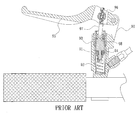
- a conventional handle structure used in a brake of a bicycle includes a body 90 integrally formed by a casting or forging method, and then the body 90 is drilled and milled by using a lathe.
- the body 90 includes a hydraulic cylinder 91 work formed therein, and the hydraulic cylinder includes a returning spring 92, a hydraulic piston 93, and a washer 94 installed therein, the body 90 includes a handle 95 disposed on a rear side thereof, an adjustable nut 97 and a push post 97 axially connected on a front side thereof, such that when the handle 95 is pressed, a head end 98 of the push post 97 is actuated to push the hydraulic piston 93, and then the hydraulic piston 93 pushes hydraulic oil in the hydraulic cylinder 91 to actuate a clamping and braking operation.
- the push post 97 pushes the hydraulic piston 93, and then the push post 97 pushes the hydraulic cylinder at a certain angle. Because the push post 97 is axially connected on the handle 95, and between the push post 97 and the hydraulic cylinder 91 is defined a predetermined angle, transmitting power will lose to operate the brake dully. Moreover, the conventional handle structure includes many complicated components that have to be worked, increasing production cost.
- the present invention has arisen to mitigate and/or obviate the afore-described disadvantages.
- the primary object of the present invention is to provide a hydraulic brake which is capable of overcoming the shortcomings of the conventional a hydraulic brake.
- Another object of the present invention is to provide a hydraulic brake that after the handle of the two wheel vehicle is pressed, the hydraulic piston pushes hydraulic oil in an oil chamber directly, and then the hydraulic piston operates in the oil chamber, such that the hydraulic cylinder is micro-adjusted with a changing angle of the handle so that the hydraulic piston acts linearly, thus having a smooth brake and lowering weight.
- a hydraulic brake provided by the present invention includes:
- a hydraulic brake in accordance with a preferred embodiment of the present invention is used to a handle 50 of a two wheel vehicle, and an adjustable nut 53 of the handle 50 is screwed with a connecting post 311 of a hydraulic piston 31, the hydraulic piston 31 is used to push hydraulic oil in an oil chamber 33 when the handle 50 is pressed by a user, wherein when the hydraulic piston 31 operates in the oil chamber 33, a hydraulic cylinder 30 is micro-adjusted with a changing angle of the handle 50 so that the hydraulic piston 31 acts linearly, thus having a smooth brake and lowering weight of the hydraulic brake.
- the hydraulic brake comprises a body 20, the hydraulic cylinder 30, the hydraulic piston 31, a holder 40, the adjustable nut 53, and the handle 50, wherein the body 20 is integrally formed, includes a plurality of hollow portions 21 to lower weight, includes two first tabs 22 disposed on an upper side thereof, and each first tab 22 is inserted and screwed by a first screw 23 and a first nut 24 to axially connect the handle 50 onto the body 20;
- the handle 50 includes an axial hole 51 and a through bore 52 to receive the adjustable nut 53 arranged on a front end thereof, the adjustable nut 53 includes a screw aperture 54 formed on a middle section thereof to be screwed with first threads 312 of the connecting post 311 of the hydraulic piston 31;
- the body 20 also includes a retaining sleeve 25 and two second tabs 26 to be inserted by a second screw 27 and a second nut 28 so that the hydraulic cylinder 30 is axially connected with the body 20 and the body 20 is retained onto a grip 80;
Landscapes
- Engineering & Computer Science (AREA)
- Mechanical Engineering (AREA)
- Transportation (AREA)
- Transmission Of Braking Force In Braking Systems (AREA)
- Braking Arrangements (AREA)
- Braking Elements And Transmission Devices (AREA)
- Steering Devices For Bicycles And Motorcycles (AREA)
Abstract
Description
- The present invention relates to a hydraulic brake that can obtain a smooth brake and lower weight.
- As shown in
Fig. 1 , a conventional handle structure used in a brake of a bicycle includes abody 90 integrally formed by a casting or forging method, and then thebody 90 is drilled and milled by using a lathe. Thebody 90 includes ahydraulic cylinder 91 work formed therein, and the hydraulic cylinder includes a returningspring 92, ahydraulic piston 93, and awasher 94 installed therein, thebody 90 includes ahandle 95 disposed on a rear side thereof, anadjustable nut 97 and apush post 97 axially connected on a front side thereof, such that when thehandle 95 is pressed, ahead end 98 of thepush post 97 is actuated to push thehydraulic piston 93, and then thehydraulic piston 93 pushes hydraulic oil in thehydraulic cylinder 91 to actuate a clamping and braking operation. - However, after the
handle 95 of thebody 90 is pressed, thepush post 97 pushes thehydraulic piston 93, and then thepush post 97 pushes the hydraulic cylinder at a certain angle. Because thepush post 97 is axially connected on thehandle 95, and between thepush post 97 and thehydraulic cylinder 91 is defined a predetermined angle, transmitting power will lose to operate the brake dully. Moreover, the conventional handle structure includes many complicated components that have to be worked, increasing production cost. - The present invention has arisen to mitigate and/or obviate the afore-described disadvantages.
- The primary object of the present invention is to provide a hydraulic brake which is capable of overcoming the shortcomings of the conventional a hydraulic brake.
- Another object of the present invention is to provide a hydraulic brake that after the handle of the two wheel vehicle is pressed, the hydraulic piston pushes hydraulic oil in an oil chamber directly, and then the hydraulic piston operates in the oil chamber, such that the hydraulic cylinder is micro-adjusted with a changing angle of the handle so that the hydraulic piston acts linearly, thus having a smooth brake and lowering weight.
- To obtain the above objectives, a hydraulic brake provided by the present invention includes:
- a body, a hydraulic cylinder, a hydraulic piston, a holder, and an adjustable nut, and the handle, wherein the body includes two first tabs disposed on an upper side thereof, the handle includes an axial hole and a through bore to receive the adjustable nut arranged on a front end thereof, the adjustable nut includes a screw aperture formed on a middle section thereof to be screwed with first threads of a connecting post of the hydraulic piston, the body includes a retaining sleeve and two second tabs disposed on a bottom side thereof, the hydraulic cylinder includes an oil chamber fixed on a central portion thereof and is fitted to the holder, a positioning nut having an orifice is screwed with second threads on a top end of the hydraulic cylinder so that the hydraulic piston is limited in the oil chamber to operate and the holder is not disengaged, the holder includes a receiving room to receive an oil cup and a pore arranged thereon, and includes a cover disposed to one side thereof, an outer diameter of the pore of the holder is equal to that of the hydraulic cylinder, the pore is used to receive the hydraulic cylinder so that the hydraulic cylinder is connected with the oil cup, the hydraulic piston includes the connecting post disposed on a rear end thereof, and the connecting post includes the first threads arranged thereon to screw the connecting post with the orifice of the positioning nut.
-
-
Fig. 1 is a cross sectional view showing the assembly of a conventional hydraulic brake; -
Fig. 2 is a perspective view showing the exploded components of a hydraulic brake according to a preferred embodiment of the present invention; -
Fig. 3 is a perspective view showing the assembly of the hydraulic brake according to the preferred embodiment of the present invention; -
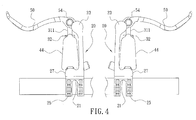
Fig. 4 is a plan view showing the assembly of the hydraulic brake according to the preferred embodiment of the present invention; -
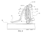
Fig. 5 is a cross sectional view showing the operation of hydraulic brake according to the preferred embodiment of the present invention; -
Fig. 6 is another cross sectional view showing the operation of hydraulic brake according to the preferred embodiment of the present invention. - The present invention will be clearer from the following description when viewed together with the accompanying drawings, which show, for purpose of illustrations only, the preferred embodiment in accordance with the present invention.
- Referring to
Figs. 1-6 , a hydraulic brake in accordance with a preferred embodiment of the present invention is used to ahandle 50 of a two wheel vehicle, and anadjustable nut 53 of thehandle 50 is screwed with a connectingpost 311 of ahydraulic piston 31, thehydraulic piston 31 is used to push hydraulic oil in anoil chamber 33 when thehandle 50 is pressed by a user, wherein when thehydraulic piston 31 operates in theoil chamber 33, ahydraulic cylinder 30 is micro-adjusted with a changing angle of thehandle 50 so that thehydraulic piston 31 acts linearly, thus having a smooth brake and lowering weight of the hydraulic brake. - The hydraulic brake comprises a
body 20, thehydraulic cylinder 30, thehydraulic piston 31, aholder 40, theadjustable nut 53, and thehandle 50, wherein thebody 20 is integrally formed, includes a plurality ofhollow portions 21 to lower weight, includes twofirst tabs 22 disposed on an upper side thereof, and eachfirst tab 22 is inserted and screwed by afirst screw 23 and afirst nut 24 to axially connect thehandle 50 onto thebody 20; thehandle 50 includes anaxial hole 51 and athrough bore 52 to receive theadjustable nut 53 arranged on a front end thereof, theadjustable nut 53 includes ascrew aperture 54 formed on a middle section thereof to be screwed withfirst threads 312 of the connectingpost 311 of thehydraulic piston 31; thebody 20 also includes aretaining sleeve 25 and twosecond tabs 26 to be inserted by asecond screw 27 and asecond nut 28 so that thehydraulic cylinder 30 is axially connected with thebody 20 and thebody 20 is retained onto agrip 80; thehydraulic cylinder 30 includes theoil chamber 33 fixed on a central portion thereof and is fitted to theholder 40, theoil chamber 33 includes a returningspring 34 and thehydraulic piston 31 installed therein, and apositioning nut 32 having anorifice 321 is screwed withsecond threads 35 on a top end of thehydraulic cylinder 30 so that thehydraulic piston 31 is limited in theoil chamber 33 to operate and theholder 40 is not disengaged, thehydraulic cylinder 30 also includes anopening 36 mounted on a bottom end thereof, and theopening 36 includes anoutlet 37 fixed on one side thereof to be coupled with thesecond tabs 26 of thebody 20, thehydraulic cylinder 30 includes a plurality ofmouths 38 secured on a middle section thereof to communicate with anoil cup 43; theholder 40 includes areceiving room 41 to receive theoil cup 43 and apore 42 arranged thereon, and includes acover 44 disposed to one side thereof and screwed with theoil cup 43 by using a plurality of screw elements, an outer diameter of thepore 42 of theholder 40 is equal to that of thehydraulic cylinder 30, and thepore 42 is used to receive thehydraulic cylinder 30 so that thehydraulic cylinder 30 is connected with theholder 40, thehydraulic piston 31 includes the connectingpost 311 disposed on a rear end thereof, and the connectingpost 311 includes thefirst threads 312 arranged thereon to screw the connectingpost 311 with theorifice 321 of thepositioning nut 32, such that the hydraulic brake is assembled to be operated smoothly and obtain a light weight. - While we have shown and described various embodiments in accordance with the present invention, it is clear to those skilled in the art that further embodiments may be made without departing from the scope of the present invention.
Claims (10)
- A hydraulic brake being used to a handle (50) of a two wheel vehicle and comprising a body (20), a hydraulic cylinder (30), a hydraulic piston (31), a holder (40), and an adjustable nut (53), and the handle (50), wherein the body (20) includes two first tabs (22) disposed on an upper side thereof, the handle (50) includes an axial hole (51) and a through bore (52) to receive the adjustable nut (53) arranged on a front end thereof, the adjustable nut (53) includes a screw aperture (54) formed on a middle section thereof to be screwed with first threads (312) of a connecting post (311) of the hydraulic piston (31), the body (20) includes a retaining sleeve (25) and two second tabs (26) disposed on a bottom side thereof, the hydraulic cylinder (30) includes an oil chamber (33) fixed on a central portion thereof and is fitted to the holder (40), a positioning nut (32) having an orifice (321) is screwed with second threads (35) on a top end of the hydraulic cylinder (30) so that the hydraulic piston (31) is limited in the oil chamber (33) to operate and the holder (40) is not disengaged, the holder (40) includes a receiving room (41) to receive an oil cup (43) and a pore (42) arranged thereon, and includes a cover (44) disposed to one side thereof, an outer diameter of the pore (42) of the holder (40) is equal to that of the hydraulic cylinder (30), the pore (42) is used to receive the hydraulic cylinder (30) so that the hydraulic cylinder (30) is connected with the oil cup (43), the hydraulic piston (31) includes the connecting post (311) disposed on a rear end thereof, and the connecting post (311) includes the first threads (312) arranged thereon to screw the connecting post (311) with the orifice (321) of the positioning nut (32).
- The hydraulic brake as claimed in claim 1, wherein the hydraulic piston (31) is used to push hydraulic oil in an oil chamber (33) when the handle (50) is pressed by a user.
- The hydraulic brake as claimed in claim 1, wherein when the hydraulic piston (31) operates in the oil chamber (33), the hydraulic cylinder (30) is micro-adjusted with a changing angle of the handle (50) so that the hydraulic piston (31) acts linearly.
- The hydraulic brake as claimed in claim 1, wherein the body (20) is integrally formed, includes a plurality of hollow portions (21) to lower weight.
- The hydraulic brake as claimed in claim 1, wherein each first tab (22) is inserted and screwed by a first screw (23) and a first nut (24) to axially connect the handle (50) onto the body (20).
- The hydraulic brake as claimed in claim 1, wherein the retaining sleeve (25) and the second tabs (26) of the body (20) are inserted by a second screw (27) and a second nut (28) so that the hydraulic cylinder (30) is axially connected with the body (20) and the body (20) is retained onto a grip (80).
- The hydraulic brake as claimed in claim 1, wherein the oil chamber (33) includes a returning spring (34) and the hydraulic piston (31) installed therein.
- The hydraulic brake as claimed in claim 1, wherein the hydraulic cylinder (30) includes an opening (36) mounted on a bottom end thereof, and the opening (36) includes an outlet (37) fixed on one side thereof to be coupled with the second tabs (26) of the body (20).
- The hydraulic brake as claimed in claim 1, wherein the hydraulic cylinder (30) includes a plurality of mouths (38) secured on a middle section thereof to communicate with the oil cup (43).
- The hydraulic brake as claimed in claim 1, wherein the cover (44) is disposed to one side of the holder (40) and screwed with the oil cup (43) by using a plurality of screw elements.
Applications Claiming Priority (1)
| Application Number | Priority Date | Filing Date | Title |
|---|---|---|---|
| TW99203274U TWM390914U (en) | 2010-02-12 | 2010-02-12 |
Publications (3)
| Publication Number | Publication Date |
|---|---|
| EP2360087A1 true EP2360087A1 (en) | 2011-08-24 |
| EP2360087A8 EP2360087A8 (en) | 2012-06-13 |
| EP2360087B1 EP2360087B1 (en) | 2013-05-08 |
Family
ID=43733188
Family Applications (1)
| Application Number | Title | Priority Date | Filing Date |
|---|---|---|---|
| EP20110151256 Not-in-force EP2360087B1 (en) | 2010-02-12 | 2011-01-18 | Hydraulic brake |
Country Status (3)
| Country | Link |
|---|---|
| EP (1) | EP2360087B1 (en) |
| ES (1) | ES2406763T3 (en) |
| TW (1) | TWM390914U (en) |
Cited By (2)
| Publication number | Priority date | Publication date | Assignee | Title |
|---|---|---|---|---|
| CN112758234A (en) * | 2021-01-29 | 2021-05-07 | 重庆宗申创新技术研究院有限公司 | Novel motorcycle brake handle structure |
| DE102013003767B4 (en) | 2012-03-30 | 2022-10-06 | Shimano Inc. | Actuating device for a hydraulic bicycle component |
Families Citing this family (2)
| Publication number | Priority date | Publication date | Assignee | Title |
|---|---|---|---|---|
| TWM390914U (en) * | 2010-02-12 | 2010-10-21 | ||
| US9365260B2 (en) | 2012-04-18 | 2016-06-14 | Shimano Inc. | Bicycle hydraulic operating device |
Citations (6)
| Publication number | Priority date | Publication date | Assignee | Title |
|---|---|---|---|---|
| US6370877B1 (en) * | 2001-01-30 | 2002-04-16 | Chang Hui Lin | Brake handle device for hydraulic brake assembly |
| EP1398259A2 (en) * | 2002-09-12 | 2004-03-17 | Spiegler Bremstechnik GmbH | Operating lever |
| EP1693244A2 (en) * | 2005-02-18 | 2006-08-23 | Shimano Inc. | Hydraulic disc brake lever assembly |
| US20080116025A1 (en) * | 2001-12-28 | 2008-05-22 | Sram Corporation | Symmetric Master Cylinder Lever for a Hydraulic Disc Brake II |
| US20100224740A1 (en) * | 2009-03-06 | 2010-09-09 | Shimano Inc. | Bicycle component fixing band |
| TWM390914U (en) * | 2010-02-12 | 2010-10-21 |
-
2010
- 2010-02-12 TW TW99203274U patent/TWM390914U/zh not_active IP Right Cessation
-
2011
- 2011-01-18 EP EP20110151256 patent/EP2360087B1/en not_active Not-in-force
- 2011-01-18 ES ES11151256T patent/ES2406763T3/en active Active
Patent Citations (6)
| Publication number | Priority date | Publication date | Assignee | Title |
|---|---|---|---|---|
| US6370877B1 (en) * | 2001-01-30 | 2002-04-16 | Chang Hui Lin | Brake handle device for hydraulic brake assembly |
| US20080116025A1 (en) * | 2001-12-28 | 2008-05-22 | Sram Corporation | Symmetric Master Cylinder Lever for a Hydraulic Disc Brake II |
| EP1398259A2 (en) * | 2002-09-12 | 2004-03-17 | Spiegler Bremstechnik GmbH | Operating lever |
| EP1693244A2 (en) * | 2005-02-18 | 2006-08-23 | Shimano Inc. | Hydraulic disc brake lever assembly |
| US20100224740A1 (en) * | 2009-03-06 | 2010-09-09 | Shimano Inc. | Bicycle component fixing band |
| TWM390914U (en) * | 2010-02-12 | 2010-10-21 |
Cited By (2)
| Publication number | Priority date | Publication date | Assignee | Title |
|---|---|---|---|---|
| DE102013003767B4 (en) | 2012-03-30 | 2022-10-06 | Shimano Inc. | Actuating device for a hydraulic bicycle component |
| CN112758234A (en) * | 2021-01-29 | 2021-05-07 | 重庆宗申创新技术研究院有限公司 | Novel motorcycle brake handle structure |
Also Published As
| Publication number | Publication date |
|---|---|
| ES2406763T3 (en) | 2013-06-10 |
| EP2360087B1 (en) | 2013-05-08 |
| TWM390914U (en) | 2010-10-21 |
| EP2360087A8 (en) | 2012-06-13 |
Similar Documents
| Publication | Publication Date | Title |
|---|---|---|
| US20130192941A1 (en) | Hydraulic brake | |
| US6279703B1 (en) | Shock absorbing adjusting structure | |
| US6574846B1 (en) | Tool set for replacing brake pads of disc braking systems | |
| EP2360087A1 (en) | Hydraulic brake | |
| US20040123438A1 (en) | Tool for replacing brake pads of disc braking systems of automobiles | |
| US20160375952A1 (en) | Hydraulic brake | |
| US9004245B2 (en) | Hydraulic brake system | |
| US8347765B2 (en) | Axial connecting structure of pliers | |
| US20140231202A1 (en) | Hydraulic brake adjusting device | |
| US20100051400A1 (en) | Hydraulic brake lever device for bicycle | |
| US9874238B2 (en) | Bicycle end cap | |
| US20060180630A1 (en) | Intake distributing device of a rivet-nut gun | |
| CA2454464A1 (en) | Bicycle crank arm assembly | |
| US20110290601A1 (en) | Hydraulic Brake | |
| CN105035242A (en) | Bicycle component operating apparatus | |
| US20120118112A1 (en) | Ratchet Wrench | |
| US20220184789A1 (en) | Removal Apparatus of Threaded Post | |
| US9567033B2 (en) | Rotor system for a bicycle | |
| CA2704401A1 (en) | T-600 gas braking tool | |
| US20160144470A1 (en) | Installation device for a vehicle cylinder and installation assembly having the same | |
| US5003839A (en) | Stem having a fixing device | |
| EP2412620A1 (en) | Connecting and adjusting structure for crank assembly | |
| US10011320B2 (en) | Wheel hub with an axial-braking assembly | |
| US20140300073A1 (en) | Bicycle suspension system | |
| US20100229676A1 (en) | Quick release device |
Legal Events
| Date | Code | Title | Description |
|---|---|---|---|
| PUAI | Public reference made under article 153(3) epc to a published international application that has entered the european phase |
Free format text: ORIGINAL CODE: 0009012 |
|
| 17P | Request for examination filed |
Effective date: 20110510 |
|
| AK | Designated contracting states |
Kind code of ref document: A1 Designated state(s): AL AT BE BG CH CY CZ DE DK EE ES FI FR GB GR HR HU IE IS IT LI LT LU LV MC MK MT NL NO PL PT RO RS SE SI SK SM TR |
|
| AX | Request for extension of the european patent |
Extension state: BA ME |
|
| 17Q | First examination report despatched |
Effective date: 20120516 |
|
| GRAP | Despatch of communication of intention to grant a patent |
Free format text: ORIGINAL CODE: EPIDOSNIGR1 |
|
| GRAS | Grant fee paid |
Free format text: ORIGINAL CODE: EPIDOSNIGR3 |
|
| GRAA | (expected) grant |
Free format text: ORIGINAL CODE: 0009210 |
|
| AK | Designated contracting states |
Kind code of ref document: B1 Designated state(s): AL AT BE BG CH CY CZ DE DK EE ES FI FR GB GR HR HU IE IS IT LI LT LU LV MC MK MT NL NO PL PT RO RS SE SI SK SM TR |
|
| REG | Reference to a national code |
Ref country code: GB Ref legal event code: FG4D |
|
| REG | Reference to a national code |
Ref country code: AT Ref legal event code: REF Ref document number: 610935 Country of ref document: AT Kind code of ref document: T Effective date: 20130515 Ref country code: CH Ref legal event code: EP |
|
| REG | Reference to a national code |
Ref country code: ES Ref legal event code: FG2A Ref document number: 2406763 Country of ref document: ES Kind code of ref document: T3 Effective date: 20130610 |
|
| REG | Reference to a national code |
Ref country code: IE Ref legal event code: FG4D |
|
| REG | Reference to a national code |
Ref country code: DE Ref legal event code: R096 Ref document number: 602011001568 Country of ref document: DE Effective date: 20130704 |
|
| REG | Reference to a national code |
Ref country code: AT Ref legal event code: MK05 Ref document number: 610935 Country of ref document: AT Kind code of ref document: T Effective date: 20130508 |
|
| REG | Reference to a national code |
Ref country code: LT Ref legal event code: MG4D |
|
| REG | Reference to a national code |
Ref country code: NL Ref legal event code: VDEP Effective date: 20130508 |
|
| PG25 | Lapsed in a contracting state [announced via postgrant information from national office to epo] |
Ref country code: NO Free format text: LAPSE BECAUSE OF FAILURE TO SUBMIT A TRANSLATION OF THE DESCRIPTION OR TO PAY THE FEE WITHIN THE PRESCRIBED TIME-LIMIT Effective date: 20130808 Ref country code: PT Free format text: LAPSE BECAUSE OF FAILURE TO SUBMIT A TRANSLATION OF THE DESCRIPTION OR TO PAY THE FEE WITHIN THE PRESCRIBED TIME-LIMIT Effective date: 20130909 Ref country code: SE Free format text: LAPSE BECAUSE OF FAILURE TO SUBMIT A TRANSLATION OF THE DESCRIPTION OR TO PAY THE FEE WITHIN THE PRESCRIBED TIME-LIMIT Effective date: 20130508 Ref country code: SI Free format text: LAPSE BECAUSE OF FAILURE TO SUBMIT A TRANSLATION OF THE DESCRIPTION OR TO PAY THE FEE WITHIN THE PRESCRIBED TIME-LIMIT Effective date: 20130508 Ref country code: IS Free format text: LAPSE BECAUSE OF FAILURE TO SUBMIT A TRANSLATION OF THE DESCRIPTION OR TO PAY THE FEE WITHIN THE PRESCRIBED TIME-LIMIT Effective date: 20130908 Ref country code: FI Free format text: LAPSE BECAUSE OF FAILURE TO SUBMIT A TRANSLATION OF THE DESCRIPTION OR TO PAY THE FEE WITHIN THE PRESCRIBED TIME-LIMIT Effective date: 20130508 Ref country code: AT Free format text: LAPSE BECAUSE OF FAILURE TO SUBMIT A TRANSLATION OF THE DESCRIPTION OR TO PAY THE FEE WITHIN THE PRESCRIBED TIME-LIMIT Effective date: 20130508 Ref country code: LT Free format text: LAPSE BECAUSE OF FAILURE TO SUBMIT A TRANSLATION OF THE DESCRIPTION OR TO PAY THE FEE WITHIN THE PRESCRIBED TIME-LIMIT Effective date: 20130508 |
|
| PG25 | Lapsed in a contracting state [announced via postgrant information from national office to epo] |
Ref country code: CY Free format text: LAPSE BECAUSE OF FAILURE TO SUBMIT A TRANSLATION OF THE DESCRIPTION OR TO PAY THE FEE WITHIN THE PRESCRIBED TIME-LIMIT Effective date: 20130508 Ref country code: HR Free format text: LAPSE BECAUSE OF FAILURE TO SUBMIT A TRANSLATION OF THE DESCRIPTION OR TO PAY THE FEE WITHIN THE PRESCRIBED TIME-LIMIT Effective date: 20130508 Ref country code: RS Free format text: LAPSE BECAUSE OF FAILURE TO SUBMIT A TRANSLATION OF THE DESCRIPTION OR TO PAY THE FEE WITHIN THE PRESCRIBED TIME-LIMIT Effective date: 20130508 Ref country code: PL Free format text: LAPSE BECAUSE OF FAILURE TO SUBMIT A TRANSLATION OF THE DESCRIPTION OR TO PAY THE FEE WITHIN THE PRESCRIBED TIME-LIMIT Effective date: 20130508 Ref country code: BG Free format text: LAPSE BECAUSE OF FAILURE TO SUBMIT A TRANSLATION OF THE DESCRIPTION OR TO PAY THE FEE WITHIN THE PRESCRIBED TIME-LIMIT Effective date: 20130808 |
|
| PG25 | Lapsed in a contracting state [announced via postgrant information from national office to epo] |
Ref country code: LV Free format text: LAPSE BECAUSE OF FAILURE TO SUBMIT A TRANSLATION OF THE DESCRIPTION OR TO PAY THE FEE WITHIN THE PRESCRIBED TIME-LIMIT Effective date: 20130508 |
|
| PG25 | Lapsed in a contracting state [announced via postgrant information from national office to epo] |
Ref country code: BE Free format text: LAPSE BECAUSE OF FAILURE TO SUBMIT A TRANSLATION OF THE DESCRIPTION OR TO PAY THE FEE WITHIN THE PRESCRIBED TIME-LIMIT Effective date: 20130508 Ref country code: SK Free format text: LAPSE BECAUSE OF FAILURE TO SUBMIT A TRANSLATION OF THE DESCRIPTION OR TO PAY THE FEE WITHIN THE PRESCRIBED TIME-LIMIT Effective date: 20130508 Ref country code: DK Free format text: LAPSE BECAUSE OF FAILURE TO SUBMIT A TRANSLATION OF THE DESCRIPTION OR TO PAY THE FEE WITHIN THE PRESCRIBED TIME-LIMIT Effective date: 20130508 Ref country code: EE Free format text: LAPSE BECAUSE OF FAILURE TO SUBMIT A TRANSLATION OF THE DESCRIPTION OR TO PAY THE FEE WITHIN THE PRESCRIBED TIME-LIMIT Effective date: 20130508 Ref country code: CZ Free format text: LAPSE BECAUSE OF FAILURE TO SUBMIT A TRANSLATION OF THE DESCRIPTION OR TO PAY THE FEE WITHIN THE PRESCRIBED TIME-LIMIT Effective date: 20130508 |
|
| PG25 | Lapsed in a contracting state [announced via postgrant information from national office to epo] |
Ref country code: RO Free format text: LAPSE BECAUSE OF FAILURE TO SUBMIT A TRANSLATION OF THE DESCRIPTION OR TO PAY THE FEE WITHIN THE PRESCRIBED TIME-LIMIT Effective date: 20130508 Ref country code: NL Free format text: LAPSE BECAUSE OF FAILURE TO SUBMIT A TRANSLATION OF THE DESCRIPTION OR TO PAY THE FEE WITHIN THE PRESCRIBED TIME-LIMIT Effective date: 20130508 |
|
| PLBE | No opposition filed within time limit |
Free format text: ORIGINAL CODE: 0009261 |
|
| STAA | Information on the status of an ep patent application or granted ep patent |
Free format text: STATUS: NO OPPOSITION FILED WITHIN TIME LIMIT |
|
| 26N | No opposition filed |
Effective date: 20140211 |
|
| REG | Reference to a national code |
Ref country code: DE Ref legal event code: R097 Ref document number: 602011001568 Country of ref document: DE Effective date: 20140211 |
|
| PG25 | Lapsed in a contracting state [announced via postgrant information from national office to epo] |
Ref country code: LU Free format text: LAPSE BECAUSE OF FAILURE TO SUBMIT A TRANSLATION OF THE DESCRIPTION OR TO PAY THE FEE WITHIN THE PRESCRIBED TIME-LIMIT Effective date: 20140118 |
|
| REG | Reference to a national code |
Ref country code: IE Ref legal event code: MM4A |
|
| PG25 | Lapsed in a contracting state [announced via postgrant information from national office to epo] |
Ref country code: IE Free format text: LAPSE BECAUSE OF NON-PAYMENT OF DUE FEES Effective date: 20140118 |
|
| PG25 | Lapsed in a contracting state [announced via postgrant information from national office to epo] |
Ref country code: MC Free format text: LAPSE BECAUSE OF FAILURE TO SUBMIT A TRANSLATION OF THE DESCRIPTION OR TO PAY THE FEE WITHIN THE PRESCRIBED TIME-LIMIT Effective date: 20130508 |
|
| REG | Reference to a national code |
Ref country code: FR Ref legal event code: PLFP Year of fee payment: 6 |
|
| PG25 | Lapsed in a contracting state [announced via postgrant information from national office to epo] |
Ref country code: MT Free format text: LAPSE BECAUSE OF FAILURE TO SUBMIT A TRANSLATION OF THE DESCRIPTION OR TO PAY THE FEE WITHIN THE PRESCRIBED TIME-LIMIT Effective date: 20130508 |
|
| PG25 | Lapsed in a contracting state [announced via postgrant information from national office to epo] |
Ref country code: SM Free format text: LAPSE BECAUSE OF FAILURE TO SUBMIT A TRANSLATION OF THE DESCRIPTION OR TO PAY THE FEE WITHIN THE PRESCRIBED TIME-LIMIT Effective date: 20130508 |
|
| PG25 | Lapsed in a contracting state [announced via postgrant information from national office to epo] |
Ref country code: GR Free format text: LAPSE BECAUSE OF FAILURE TO SUBMIT A TRANSLATION OF THE DESCRIPTION OR TO PAY THE FEE WITHIN THE PRESCRIBED TIME-LIMIT Effective date: 20130508 |
|
| PG25 | Lapsed in a contracting state [announced via postgrant information from national office to epo] |
Ref country code: HU Free format text: LAPSE BECAUSE OF FAILURE TO SUBMIT A TRANSLATION OF THE DESCRIPTION OR TO PAY THE FEE WITHIN THE PRESCRIBED TIME-LIMIT; INVALID AB INITIO Effective date: 20110118 Ref country code: TR Free format text: LAPSE BECAUSE OF FAILURE TO SUBMIT A TRANSLATION OF THE DESCRIPTION OR TO PAY THE FEE WITHIN THE PRESCRIBED TIME-LIMIT Effective date: 20130508 |
|
| REG | Reference to a national code |
Ref country code: FR Ref legal event code: PLFP Year of fee payment: 7 |
|
| REG | Reference to a national code |
Ref country code: FR Ref legal event code: PLFP Year of fee payment: 8 |
|
| PGFP | Annual fee paid to national office [announced via postgrant information from national office to epo] |
Ref country code: GB Payment date: 20180130 Year of fee payment: 8 Ref country code: ES Payment date: 20180212 Year of fee payment: 8 Ref country code: DE Payment date: 20180126 Year of fee payment: 8 Ref country code: CH Payment date: 20180129 Year of fee payment: 8 |
|
| PGFP | Annual fee paid to national office [announced via postgrant information from national office to epo] |
Ref country code: IT Payment date: 20180125 Year of fee payment: 8 Ref country code: FR Payment date: 20180130 Year of fee payment: 8 |
|
| PG25 | Lapsed in a contracting state [announced via postgrant information from national office to epo] |
Ref country code: MK Free format text: LAPSE BECAUSE OF FAILURE TO SUBMIT A TRANSLATION OF THE DESCRIPTION OR TO PAY THE FEE WITHIN THE PRESCRIBED TIME-LIMIT Effective date: 20130508 |
|
| PG25 | Lapsed in a contracting state [announced via postgrant information from national office to epo] |
Ref country code: AL Free format text: LAPSE BECAUSE OF FAILURE TO SUBMIT A TRANSLATION OF THE DESCRIPTION OR TO PAY THE FEE WITHIN THE PRESCRIBED TIME-LIMIT Effective date: 20130508 |
|
| REG | Reference to a national code |
Ref country code: DE Ref legal event code: R119 Ref document number: 602011001568 Country of ref document: DE |
|
| REG | Reference to a national code |
Ref country code: CH Ref legal event code: PL |
|
| GBPC | Gb: european patent ceased through non-payment of renewal fee |
Effective date: 20190118 |
|
| PG25 | Lapsed in a contracting state [announced via postgrant information from national office to epo] |
Ref country code: DE Free format text: LAPSE BECAUSE OF NON-PAYMENT OF DUE FEES Effective date: 20190801 Ref country code: FR Free format text: LAPSE BECAUSE OF NON-PAYMENT OF DUE FEES Effective date: 20190131 |
|
| PG25 | Lapsed in a contracting state [announced via postgrant information from national office to epo] |
Ref country code: CH Free format text: LAPSE BECAUSE OF NON-PAYMENT OF DUE FEES Effective date: 20190131 Ref country code: GB Free format text: LAPSE BECAUSE OF NON-PAYMENT OF DUE FEES Effective date: 20190118 Ref country code: LI Free format text: LAPSE BECAUSE OF NON-PAYMENT OF DUE FEES Effective date: 20190131 |
|
| PG25 | Lapsed in a contracting state [announced via postgrant information from national office to epo] |
Ref country code: IT Free format text: LAPSE BECAUSE OF NON-PAYMENT OF DUE FEES Effective date: 20190118 |
|
| REG | Reference to a national code |
Ref country code: ES Ref legal event code: FD2A Effective date: 20200310 |
|
| PG25 | Lapsed in a contracting state [announced via postgrant information from national office to epo] |
Ref country code: ES Free format text: LAPSE BECAUSE OF NON-PAYMENT OF DUE FEES Effective date: 20190119 |