EP2360040A1 - Machine for charging/recovering a refrigerant in a vehicle air-conditioning system - Google Patents
Machine for charging/recovering a refrigerant in a vehicle air-conditioning system Download PDFInfo
- Publication number
- EP2360040A1 EP2360040A1 EP11154594A EP11154594A EP2360040A1 EP 2360040 A1 EP2360040 A1 EP 2360040A1 EP 11154594 A EP11154594 A EP 11154594A EP 11154594 A EP11154594 A EP 11154594A EP 2360040 A1 EP2360040 A1 EP 2360040A1
- Authority
- EP
- European Patent Office
- Prior art keywords
- oil
- charging
- reservoir
- refrigerant
- type
- Prior art date
- Legal status (The legal status is an assumption and is not a legal conclusion. Google has not performed a legal analysis and makes no representation as to the accuracy of the status listed.)
- Granted
Links
Images


Classifications
-
- B—PERFORMING OPERATIONS; TRANSPORTING
- B60—VEHICLES IN GENERAL
- B60H—ARRANGEMENTS OF HEATING, COOLING, VENTILATING OR OTHER AIR-TREATING DEVICES SPECIALLY ADAPTED FOR PASSENGER OR GOODS SPACES OF VEHICLES
- B60H1/00—Heating, cooling or ventilating devices
- B60H1/00507—Details, e.g. mounting arrangements, desaeration devices
- B60H1/00585—Means for monitoring, testing or servicing the air-conditioning
-
- F—MECHANICAL ENGINEERING; LIGHTING; HEATING; WEAPONS; BLASTING
- F25—REFRIGERATION OR COOLING; COMBINED HEATING AND REFRIGERATION SYSTEMS; HEAT PUMP SYSTEMS; MANUFACTURE OR STORAGE OF ICE; LIQUEFACTION SOLIDIFICATION OF GASES
- F25B—REFRIGERATION MACHINES, PLANTS OR SYSTEMS; COMBINED HEATING AND REFRIGERATION SYSTEMS; HEAT PUMP SYSTEMS
- F25B45/00—Arrangements for charging or discharging refrigerant
-
- F—MECHANICAL ENGINEERING; LIGHTING; HEATING; WEAPONS; BLASTING
- F25—REFRIGERATION OR COOLING; COMBINED HEATING AND REFRIGERATION SYSTEMS; HEAT PUMP SYSTEMS; MANUFACTURE OR STORAGE OF ICE; LIQUEFACTION SOLIDIFICATION OF GASES
- F25B—REFRIGERATION MACHINES, PLANTS OR SYSTEMS; COMBINED HEATING AND REFRIGERATION SYSTEMS; HEAT PUMP SYSTEMS
- F25B2345/00—Details for charging or discharging refrigerants; Service stations therefor
- F25B2345/001—Charging refrigerant to a cycle
-
- F—MECHANICAL ENGINEERING; LIGHTING; HEATING; WEAPONS; BLASTING
- F25—REFRIGERATION OR COOLING; COMBINED HEATING AND REFRIGERATION SYSTEMS; HEAT PUMP SYSTEMS; MANUFACTURE OR STORAGE OF ICE; LIQUEFACTION SOLIDIFICATION OF GASES
- F25B—REFRIGERATION MACHINES, PLANTS OR SYSTEMS; COMBINED HEATING AND REFRIGERATION SYSTEMS; HEAT PUMP SYSTEMS
- F25B2345/00—Details for charging or discharging refrigerants; Service stations therefor
- F25B2345/002—Collecting refrigerant from a cycle
-
- F—MECHANICAL ENGINEERING; LIGHTING; HEATING; WEAPONS; BLASTING
- F25—REFRIGERATION OR COOLING; COMBINED HEATING AND REFRIGERATION SYSTEMS; HEAT PUMP SYSTEMS; MANUFACTURE OR STORAGE OF ICE; LIQUEFACTION SOLIDIFICATION OF GASES
- F25B—REFRIGERATION MACHINES, PLANTS OR SYSTEMS; COMBINED HEATING AND REFRIGERATION SYSTEMS; HEAT PUMP SYSTEMS
- F25B2345/00—Details for charging or discharging refrigerants; Service stations therefor
- F25B2345/003—Control issues for charging or collecting refrigerant to or from a cycle
-
- F—MECHANICAL ENGINEERING; LIGHTING; HEATING; WEAPONS; BLASTING
- F25—REFRIGERATION OR COOLING; COMBINED HEATING AND REFRIGERATION SYSTEMS; HEAT PUMP SYSTEMS; MANUFACTURE OR STORAGE OF ICE; LIQUEFACTION SOLIDIFICATION OF GASES
- F25B—REFRIGERATION MACHINES, PLANTS OR SYSTEMS; COMBINED HEATING AND REFRIGERATION SYSTEMS; HEAT PUMP SYSTEMS
- F25B2345/00—Details for charging or discharging refrigerants; Service stations therefor
- F25B2345/005—Service stations therefor
- F25B2345/0052—Service stations therefor having wheels
-
- F—MECHANICAL ENGINEERING; LIGHTING; HEATING; WEAPONS; BLASTING
- F25—REFRIGERATION OR COOLING; COMBINED HEATING AND REFRIGERATION SYSTEMS; HEAT PUMP SYSTEMS; MANUFACTURE OR STORAGE OF ICE; LIQUEFACTION SOLIDIFICATION OF GASES
- F25B—REFRIGERATION MACHINES, PLANTS OR SYSTEMS; COMBINED HEATING AND REFRIGERATION SYSTEMS; HEAT PUMP SYSTEMS
- F25B2345/00—Details for charging or discharging refrigerants; Service stations therefor
- F25B2345/006—Details for charging or discharging refrigerants; Service stations therefor characterised by charging or discharging valves
Definitions
- the present invention relates to a machine for charging/recovering a refrigerant in an air-conditioning system of a vehicle, provided with a system for automatically determining the type of oil contained in a charging reservoir which can be coupled to the machine itself.
- the present invention relates to a machine for charging/recovering a refrigerant in a vehicle air-conditioning system of the type comprising: a refrigerant recovery assembly and a main hydraulic removing/recharging circuit of the refrigerant in the vehicle air conditioning system.
- the refrigerant recovery assembly comprises a refrigerant filtering, separating and recovery circuit, to which the following are connected: a refrigerant containing reservoir and a recovery reservoir which stores the oil filtered and separated from the recovered refrigerant.
- the machine further comprises a charging reservoir, which is removably connected to the main hydraulic circuit and contains intact oil to be injected into the vehicle air conditioning system during the charging step.
- the main hydraulic circuit removes a residual amount of refrigerant from the air conditioning system to provide it to the recovery assembly, which in turns filters it to separate oil from the same, in order to supply the filtered refrigerant into the refrigerant reservoir and to supply, at the same time, the residual oil into the recovery reservoir.
- the main hydraulic circuit cooperates with the refrigerant containing reservoir and with a charging reservoir to receive the nominal amounts of refrigerant and of oil, respectively, to be supplied into the vehicle air conditioning system.
- a control system for a machine for charging/recovering a refrigerant in an vehicle air-conditioning system is made, as disclosed in claim 1 and preferably, but not necessarily, in any of the subsequent claims, depending either directly or indirectly from claim 1.
- a control method for a machine for charging/recovering a refrigerant in a vehicle air-conditioning system is provided, as disclosed in claim 12 and preferably, but not necessarily, in any of the claims depending either directly or indirectly from claim 12.
- an oil containing reservoir which can be coupled to a machine for charging/recovering a refrigerant in a vehicle air-conditioning system, is made as disclosed in claim 23.
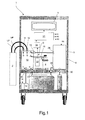
- numeral 1 indicates as a whole a machine for charging/recovering a refrigerant in an air-conditioning system 2 of a vehicle, such as for example a land vehicle, in particular a motor vehicle (schematically shown), which is provided with a system 3 for automatically determining the type of oil contained in a charging reservoir 8 which can be coupled in a stable although easily releasable manner to the machine 1 itself.
- a vehicle such as for example a land vehicle, in particular a motor vehicle (schematically shown)
- a system 3 for automatically determining the type of oil contained in a charging reservoir 8 which can be coupled in a stable although easily releasable manner to the machine 1 itself.
- machine 1 comprises a casing 4 provided with wheels resting on the ground to allow to move the machine 1, a user interface 5, a containing reservoir of the refrigerant 6 and an oil recovery reservoir 7, which are arranged preferably but not necessarily within the casing 4.
- the machine 1 further comprises a refrigerant recovery assembly 9 preferably arranged within the casing 4 and having the function of filtering and separating the recovered refrigerant from the residual oil so as to store the refrigerant in the containing reservoir 6 and, in the oil recovery reservoir 7, respectively; and a main hydraulic circuit 10 adapted to be connected to the air conditioning system of vehicle 2 and cooperating with the refrigerant recovery assembly 9, with the refrigerant containing reservoir 6, with the oil recovery reservoir 7, and with the oil charging reservoir 8 for removing/charging the refrigerant and the oil from/into the vehicle air conditioning system 2.
- a refrigerant recovery assembly 9 preferably arranged within the casing 4 and having the function of filtering and separating the recovered refrigerant from the residual oil so as to store the refrigerant in the containing reservoir 6 and, in the oil recovery reservoir 7, respectively
- a main hydraulic circuit 10 adapted to be connected to the air conditioning system of vehicle 2 and cooperating with the refrigerant recovery assembly 9, with the refrigerant containing reservoir 6,
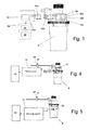
- the main hydraulic circuit 10 comprises: a connector 11 connectable to the air conditioning system 2 by means of a high pressure pipe HP; a connector 12 connectable to the air conditioning system 2 by means of a low pressure pipe LP; a connector 13 connected to a vacuum pump 14; a connector 15 connectable in a stable although easily releasable manner to the charging reservoir 8 of the oil; a connector 16 connectable to the oil recovery assembly 9; and an inlet connector 17 connected to an outlet of the refrigerant containing reservoir 6 to receive the refrigerant upon command.
- the main hydraulic circuit 10 further comprises a main pipe or manifold 19, which is connected to the connectors 11-13 and 15-17 through hydraulic segments or branches 20, and a series of interception valves arranged along the hydraulic branches 20 between the connectors 11-13 and 15-17 and the main manifold 19 and selectively controllable to be opened/closed by means of respective electric control signals to alternatively prevent, upon command, the passage of a fluid through the hydraulic branches 20 themselves.
- the main hydraulic circuit 10 comprises: an interception valve 21 arranged along the hydraulic branch 20 between the connector 11 and the main manifold 19; an interception valve 22 arranged along the hydraulic branch 20 between the connector 12 and the main manifold 19; an interception valve 23 arranged along the hydraulic branch 20 between the connector 13 and the main manifold 19; an interception valve 24 arranged along the hydraulic branch 20 between the connector 13 and the main manifold 19; an interception valve 25 arranged along the hydraulic branch 20 between the connector 16 and the main manifold 19; and an interception valve 26 arranged along the hydraulic branch 20 between the inlet manifold 17 and the main manifold 19.
- the refrigerant recovery assembly 9 instead comprises a recovery hydraulic circuit 9a having an inlet 28 connected, by means of a pipe, to the connector 16 of the main hydraulic circuit 10 to receive the recovered refrigerant, an outlet 29 connected, by means of a pipe, to an inlet of the refrigerant containing reservoir 6, and an outlet 30 connected to the oil recovery reservoir 7.
- the refrigerant recovery assembly 9 further comprises a series of filtering devices arranged along the hydraulic recovery circuit 9a, and a compressor 9b which is connected to the hydraulic recovery circuit 9a so as to be able to generate, upon command, a vacuum in the hydraulic recovery circuit 9a itself.
- the refrigerant recovery assembly 9 is of known type and thus will not be described further except for specifying that it is configured so as to: receive the recovered refrigerant from the main hydraulic circuit 10 through inlet 28,; separate the refrigerant from the oil; supply the separated refrigerant to be conveyed in the refrigerant containing reservoir 6 to the outlet 29; and supply the recovered oil to be conveyed into the oil recovery reservoir 7 to output 30.
- the machine 1 further comprises an electronic control unit 31, which is configured so as to generate control signals Si for controlling the opening/closing of the interception valves 21-26; a control signal SC which controls the on/off switching of the vacuum pump 14; and control signals SG which control the operation of the refrigerant recovery assembly 9.
- an electronic control unit 31 which is configured so as to generate control signals Si for controlling the opening/closing of the interception valves 21-26; a control signal SC which controls the on/off switching of the vacuum pump 14; and control signals SG which control the operation of the refrigerant recovery assembly 9.
- system 3 for automatically determining the type of oil contained in the charging reservoir 8 essentially comprises: identification means 32, which are stably integrated/fixed in/on the oil charging reservoir 8 and contain oil data which identify the type of oil contained in same; and a reading apparatus 33, which is arranged in the machine 1 and is configured to read the oil data contained in the identification means 32.
- System 3 further comprises an electronic recognition unit 34, which is configured to receive oil data read from the reading apparatus 33 so as to determine the type of oil contained in the charging reservoir 8; compare the type of oil identified by analyzing the oil data with a determined oil type and recognizes, on the basis of the comparison, a charging reservoir 8 containing an incorrect type of oil.
- an electronic recognition unit 34 configured to receive oil data read from the reading apparatus 33 so as to determine the type of oil contained in the charging reservoir 8; compare the type of oil identified by analyzing the oil data with a determined oil type and recognizes, on the basis of the comparison, a charging reservoir 8 containing an incorrect type of oil.
- the identification means 32 advantageously comprise an electronic memory card 32a containing the data related to the oil type contained in the oil charging reservoir 8, while the reading apparatus 33 comprises an electronic reading module 33a configured to access the electronic memory card 32a so as to read the data contained on the same.
- the electronic memory card 32a of the identification means 32 advantageously comprises a memory 32b containing oil data, an electronic interface circuit of the memory 32c; and an electronic connector 32d provided with a series of pins for connection to the electronic interface circuit of memory 32c; while the reading apparatus 33 installed in the machine 1 comprises the memory reading module 33a, and an electric connector 33b structured to be coupled to the electric connector 32d so as to allow the memory reading module 33a to be able to read the oil data contained in memory 32b.
- the identification means 32 advantageously comprise a TAG or RFID transponder, comprising in turn an electronic memory card 32a fixed to the charging reservoir 8; while the reading apparatus 33 comprises a RFID transponder reading module.
- the identification means 32 advantageously comprise a bar code fixed onto the charging reservoir 8 and encoding the oil data; while the reading apparatus 33 comprises a bar code reading module arranged on the machine 1 so as to read the bar code of the charging reservoir 8 when the latter is preferably but not necessarily coupled to the machine 1 itself.
- the electronic recognition unit 34 comprises a memory module 35 containing determined-oil-data related to a determined oil type; and an electronic processing device 36, which is configured so as to: receive oil data read by the reading apparatus 33; compares the read oil-data with determined-oil-data contained in the memory module 35; check whether the read oil data correspond to the determined-oil-data; and if the read oil-data are different from the determined-oil-data detects the presence of a charging reservoir 8 containing an incorrect type of oil.
- the electronic control unit 31 is configured to cooperate with the electronic recognition unit 34 and with the reading apparatus 33 to implement a program for checking/recognizing the type of oil contained in a charging reservoir 8.
- the electronic recognition unit 34 controls the reading apparatus 33 to read oil-data contained in the identification means 32 of the charging reservoir 8; compares the read oil-data with the determined-oil-data associated to the first determined type of oil, and verifies whether the oil type indicated by the read oil data corresponds to the determined oil data or not (block 110).
- the electronic recognition unit 34 detect the correspondence between oil type and indicates to the electronic control unit 31 the presence of a charging reservoir 8 containing an oil type corresponding to the required type of oil (block 120).
- the electronic recognition unit 34 determines a charging reservoir 8 containing an incorrect type of oil to the electronic control unit 31 (block 130).
- the electronic control unit 31 By detecting the presence of an incorrect charging reservoir 8, the electronic control unit 31 generates an alert message by means of a user interface 5 indicating the presence of an incorrect type of oil (block 130) and, after the replacement of the charging reservoir 8, implements the recognition operations described above again (in block 110).
- the electronic control unit 31 checks whether it is necessary to clean the main hydraulic circuit or not (block 140).
- the electronic control unit 31 verifies whether the required type of oil corresponds to the type of oil used by the machine 1 in a steps of recovering/charging immediately before the step underway.
- the electronic control unit 31 may be configured so as to memorize the oil type employed during the last charging operation and compares the newly recognized type of oil with the stored type of oil.
- the electronic control unit 31 may further be preferably but not necessarily configured so as to check whether the charging reservoir 8 was just coupled to the machine 1.
- the electronic control unit 31 may be configured so as to detect the replacement of a charging reservoir 8 controlling the electronic recognition unit 34 to send a series of electric querying signals to the electronic memory card 32a.
- the electronic control unit 31 determines that the requested type of oil does not correspond to the oil type used by the machine 1 in the previous charging operation and/or that the charging reservoir 8 was replaced (yes output from block 140), it detects the need to clean the main hydraulic circuit 10 (block 150). In this case, the electronic control unit 31 implements a program for cleaning the main hydraulic circuit 3 from the refrigerant (described above) containing the oil used in a step of recovering/charging immediately prior to the step underway.
- the electronic control unit 31 may be further configured so as to stop the charging and/or recovering operations of the refrigerant in the vehicle air conditioning system 2 when it determines that the required type of oil does not corresponds to the type of oil used by the machine 1 in the previous charging operation, and/or that the charging reservoir 8 was replaced.
- the electronic control unit 31 determines that the required type of oil corresponds to the type of oil used by the machine 1 in the previous charging operation and/or that the charging reservoir 8 was not replaced (no output from block 140), it generates the enabling signal of the charging procedure of the air conditioning system of the vehicle 2.
- the electronic control unit 31 loads the program for cleaning the hydraulic circuit which controls the opening of the interception valves 24 and 25 so as to put the charging reservoir 8 into direct communication with the refrigerant recovery assembly by means of the main manifold 19.
- the electronic control unit 31 further controls the activation of the compressor 9b of the refrigerant recovery assembly 9 so as to generate a vacuum in the hydraulic recovery circuit 9a, in order to determine both the complete removal of the latter from the remaining refrigerant present the main hydraulic circuit 10, and in particular in the segment of the hydraulic branch 20 present between the interception valve 24 and the connector 15, and the removal, by means of the main hydraulic circuit 10, within the refrigerant recovery assembly 9 itself, of a predetermined amount of oil present in the charging reservoir 8 (block 200).
- the vacuum generated in the hydraulic recovery circuit 9a removes the remaining oil from the segment of the hydraulic branch 20 comprised between the interception valve 24 and the connector 15 into the refrigerant recovery unit 9 and contextually the new oil is removed from the segment of the circuit branch itself and of the main manifold 19 ( figures 8, 9 and 10 ).
- the electronic control unit controls the closing of the interception valves 24 and 25 in order to determine the transfer of oil from the charging reservoir 8 to the refrigerant recovery unit 9 and stops the compressor 9b ( figure 10 ).
- the predetermined removal time interval is preferably dimensioned so as to guarantee the complete transfer of residual refrigerant oil and the transfer of a predetermined amount of new oil contained in the charging reservoir 8 into the main manifold 19.
- the electronic control unit 31 is configured so as to control the opening of the interception valve 26 so as to supply into the main manifold 19, by virtue of the residual vacuum remaining in the latter, a given amount of refrigerant, which is mixed with the new previously removed oil present in the main manifold 19 (block 210) ( figure 11 ).
- the electronic control unit 31 closes the interception valve 26, turns on the compressor 9b of the refrigerant recovery assembly 9 so as to generate a vacuum in the recovery circuit 9a, and opens the interception valve 25 so as to remove all the refrigerant from the main manifold 19 into the refrigerant recovery assembly 9, determining in this manner the complete cleaning of the main hydraulic circuit 10 (block 220) ( figures 12 and 13 ).
- the refrigerant recovery assembly 9 filters in known manner the oil from the removed refrigerant fluid and supplying them into the refrigerant fluid recovery reservoir 7 and in the oil recovery reservoir 8, respectively.
- the partial removal of the oil of the charging reservoir by means of the main manifold, in the recovery assembly allows to eliminate the contamination of different oils in the air conditioning system of the vehicle during the step of charging.
Landscapes
- Engineering & Computer Science (AREA)
- Physics & Mathematics (AREA)
- Mechanical Engineering (AREA)
- Thermal Sciences (AREA)
- General Engineering & Computer Science (AREA)
- Motor Or Generator Cooling System (AREA)
- Charge And Discharge Circuits For Batteries Or The Like (AREA)
- Vehicle Cleaning, Maintenance, Repair, Refitting, And Outriggers (AREA)
Abstract
Description
- The present invention relates to a machine for charging/recovering a refrigerant in an air-conditioning system of a vehicle, provided with a system for automatically determining the type of oil contained in a charging reservoir which can be coupled to the machine itself.
- In particular, the present invention relates to a machine for charging/recovering a refrigerant in a vehicle air-conditioning system of the type comprising: a refrigerant recovery assembly and a main hydraulic removing/recharging circuit of the refrigerant in the vehicle air conditioning system.
- In particular, the refrigerant recovery assembly comprises a refrigerant filtering, separating and recovery circuit, to which the following are connected: a refrigerant containing reservoir and a recovery reservoir which stores the oil filtered and separated from the recovered refrigerant.
- The machine further comprises a charging reservoir, which is removably connected to the main hydraulic circuit and contains intact oil to be injected into the vehicle air conditioning system during the charging step.
- During the recovering steps, the main hydraulic circuit removes a residual amount of refrigerant from the air conditioning system to provide it to the recovery assembly, which in turns filters it to separate oil from the same, in order to supply the filtered refrigerant into the refrigerant reservoir and to supply, at the same time, the residual oil into the recovery reservoir.
- Conversely, during the charging step, the main hydraulic circuit cooperates with the refrigerant containing reservoir and with a charging reservoir to receive the nominal amounts of refrigerant and of oil, respectively, to be supplied into the vehicle air conditioning system.
- In the machines described above there is the need to automatically identify the type of oil contained in the charging reservoir before carrying out the above-described charging operation, in order to eliminate any possibility of contamination of the vehicle system with oils which are not compatible with the system itself.
- In the machines described above, whenever the charging reservoir is replaced, the need arises to automatically eliminate the oil which remains in the main hydraulic circuit at the end of an operating cycle of the machine, so as to ensure the complete cleaning of the same before charging the refrigerant into the air conditioning system of the vehicle.
- It is the object of the present invention to make a control system for a machine for charging/recovering a refrigerant in an vehicle air-conditioning system, which automatically determine the type of oil present in the charging reservoir and warns the presence of a charging reservoir containing an incorrect oil.
- It is a further object of the present invention to make a control system for a machine for charging/recovering a refrigerant in an air-conditioning system of a vehicle, which is capable of simply cleaning the residual oil present in the main hydraulic circuit of the machine itself.
- According to the present invention, a control system for a machine for charging/recovering a refrigerant in an vehicle air-conditioning system is made, as disclosed in
claim 1 and preferably, but not necessarily, in any of the subsequent claims, depending either directly or indirectly fromclaim 1. - Furthermore, according to the present invention, a control method for a machine for charging/recovering a refrigerant in a vehicle air-conditioning system is provided, as disclosed in
claim 12 and preferably, but not necessarily, in any of the claims depending either directly or indirectly fromclaim 12. - Finally, according to the present invention, an oil containing reservoir which can be coupled to a machine for charging/recovering a refrigerant in a vehicle air-conditioning system, is made as disclosed in
claim 23. - The present invention will now be described with reference to the appended drawings, which illustrate a non-limitative embodiment thereof, in which:
-
figure 1 schematically shows a control system of a machine for charging/recovering a refrigerant according to the present invention; -
figure 2 schematically shows a main hydraulic circuit and the refrigerant recovery assembly comprised in the machine shown infigure 1 ; -
figure 3 shows a charging reservoir which can be coupled to the machine shown infigure 1 ; -
figure 4 schematically shows a first variant of the control system of a machine for charging/recovering a refrigerant shown infigure 1 ; -
figure 5 schematically shows a second variant of the control system of a machine for charging/recovering a refrigerant shown infigure 1 ; -
figure 6 shows a flow charge of the operations implemented by the system when determining the type of oil contained in the charging reservoir; -
figure 7 shows a flow chart of the operations implemented by the program for cleaning residual oil from the hydraulic circuit of the machine shown infigure 1 ; - figures from 8 to 13 schematically show an equivalent number of operative steps of the program for cleaning residual oil from the main hydraulic circuit of the machine shown in
figure 1 . - With reference to
figure 1 ,numeral 1 indicates as a whole a machine for charging/recovering a refrigerant in an air-conditioning system 2 of a vehicle, such as for example a land vehicle, in particular a motor vehicle (schematically shown), which is provided with asystem 3 for automatically determining the type of oil contained in acharging reservoir 8 which can be coupled in a stable although easily releasable manner to themachine 1 itself. - In the example shown in
figure 1 ,machine 1 comprises acasing 4 provided with wheels resting on the ground to allow to move themachine 1, auser interface 5, a containing reservoir of therefrigerant 6 and an oil recovery reservoir 7, which are arranged preferably but not necessarily within thecasing 4. - The
machine 1 further comprises arefrigerant recovery assembly 9 preferably arranged within thecasing 4 and having the function of filtering and separating the recovered refrigerant from the residual oil so as to store the refrigerant in the containingreservoir 6 and, in the oil recovery reservoir 7, respectively; and a mainhydraulic circuit 10 adapted to be connected to the air conditioning system ofvehicle 2 and cooperating with therefrigerant recovery assembly 9, with therefrigerant containing reservoir 6, with the oil recovery reservoir 7, and with theoil charging reservoir 8 for removing/charging the refrigerant and the oil from/into the vehicleair conditioning system 2. - In the example shown in
figures 1 and2 , the mainhydraulic circuit 10 comprises: aconnector 11 connectable to theair conditioning system 2 by means of a high pressure pipe HP; aconnector 12 connectable to theair conditioning system 2 by means of a low pressure pipe LP; aconnector 13 connected to avacuum pump 14; aconnector 15 connectable in a stable although easily releasable manner to thecharging reservoir 8 of the oil; aconnector 16 connectable to theoil recovery assembly 9; and aninlet connector 17 connected to an outlet of therefrigerant containing reservoir 6 to receive the refrigerant upon command. - With reference to
figure 2 , the mainhydraulic circuit 10 further comprises a main pipe ormanifold 19, which is connected to the connectors 11-13 and 15-17 through hydraulic segments orbranches 20, and a series of interception valves arranged along thehydraulic branches 20 between the connectors 11-13 and 15-17 and themain manifold 19 and selectively controllable to be opened/closed by means of respective electric control signals to alternatively prevent, upon command, the passage of a fluid through thehydraulic branches 20 themselves. - In particular, in the example schematically shown in
figure 2 , the mainhydraulic circuit 10 comprises: aninterception valve 21 arranged along thehydraulic branch 20 between theconnector 11 and themain manifold 19; aninterception valve 22 arranged along thehydraulic branch 20 between theconnector 12 and themain manifold 19; aninterception valve 23 arranged along thehydraulic branch 20 between theconnector 13 and themain manifold 19; aninterception valve 24 arranged along thehydraulic branch 20 between theconnector 13 and themain manifold 19; aninterception valve 25 arranged along thehydraulic branch 20 between theconnector 16 and themain manifold 19; and aninterception valve 26 arranged along thehydraulic branch 20 between theinlet manifold 17 and themain manifold 19. - The
refrigerant recovery assembly 9 instead comprises a recoveryhydraulic circuit 9a having aninlet 28 connected, by means of a pipe, to theconnector 16 of the mainhydraulic circuit 10 to receive the recovered refrigerant, anoutlet 29 connected, by means of a pipe, to an inlet of therefrigerant containing reservoir 6, and anoutlet 30 connected to the oil recovery reservoir 7. - In the example shown in
figure 2 , therefrigerant recovery assembly 9 further comprises a series of filtering devices arranged along thehydraulic recovery circuit 9a, and acompressor 9b which is connected to thehydraulic recovery circuit 9a so as to be able to generate, upon command, a vacuum in thehydraulic recovery circuit 9a itself. - The
refrigerant recovery assembly 9 is of known type and thus will not be described further except for specifying that it is configured so as to: receive the recovered refrigerant from the mainhydraulic circuit 10 throughinlet 28,; separate the refrigerant from the oil; supply the separated refrigerant to be conveyed in therefrigerant containing reservoir 6 to theoutlet 29; and supply the recovered oil to be conveyed into the oil recovery reservoir 7 to output 30. - With reference to
figures 1 and2 , themachine 1 further comprises anelectronic control unit 31, which is configured so as to generate control signals Si for controlling the opening/closing of the interception valves 21-26; a control signal SC which controls the on/off switching of thevacuum pump 14; and control signals SG which control the operation of therefrigerant recovery assembly 9. - With regards to
system 3 for automatically determining the type of oil contained in thecharging reservoir 8, it essentially comprises: identification means 32, which are stably integrated/fixed in/on theoil charging reservoir 8 and contain oil data which identify the type of oil contained in same; and areading apparatus 33, which is arranged in themachine 1 and is configured to read the oil data contained in theidentification means 32. -
System 3 further comprises anelectronic recognition unit 34, which is configured to receive oil data read from thereading apparatus 33 so as to determine the type of oil contained in thecharging reservoir 8; compare the type of oil identified by analyzing the oil data with a determined oil type and recognizes, on the basis of the comparison, acharging reservoir 8 containing an incorrect type of oil. - In the embodiment shown in
figure 3 , the identification means 32 advantageously comprise anelectronic memory card 32a containing the data related to the oil type contained in theoil charging reservoir 8, while thereading apparatus 33 comprises anelectronic reading module 33a configured to access theelectronic memory card 32a so as to read the data contained on the same. - More in detail, in the example shown in
figure 3 , theelectronic memory card 32a of the identification means 32 advantageously comprises amemory 32b containing oil data, an electronic interface circuit of thememory 32c; and anelectronic connector 32d provided with a series of pins for connection to the electronic interface circuit ofmemory 32c; while thereading apparatus 33 installed in themachine 1 comprises thememory reading module 33a, and anelectric connector 33b structured to be coupled to theelectric connector 32d so as to allow thememory reading module 33a to be able to read the oil data contained inmemory 32b. - According to a different embodiment shown in
figure 4 , the identification means 32 advantageously comprise a TAG or RFID transponder, comprising in turn anelectronic memory card 32a fixed to thecharging reservoir 8; while thereading apparatus 33 comprises a RFID transponder reading module. - According to a further different embodiment shown in
figure 5 , the identification means 32 advantageously comprise a bar code fixed onto thecharging reservoir 8 and encoding the oil data; while thereading apparatus 33 comprises a bar code reading module arranged on themachine 1 so as to read the bar code of thecharging reservoir 8 when the latter is preferably but not necessarily coupled to themachine 1 itself. - The
electronic recognition unit 34 comprises amemory module 35 containing determined-oil-data related to a determined oil type; and anelectronic processing device 36, which is configured so as to: receive oil data read by thereading apparatus 33; compares the read oil-data with determined-oil-data contained in thememory module 35; check whether the read oil data correspond to the determined-oil-data; and if the read oil-data are different from the determined-oil-data detects the presence of acharging reservoir 8 containing an incorrect type of oil. - The
electronic control unit 31 is configured to cooperate with theelectronic recognition unit 34 and with thereading apparatus 33 to implement a program for checking/recognizing the type of oil contained in acharging reservoir 8. - With reference to
figure 6 , the operative steps implemented by the aforesaid program for verifying/recognizing the oil type contained in thecharging reservoir 8 are described below, in which it is assumed thatmachine 1 establishes a first determined oil type (block 100) on the basis of an operating cycle to be implemented. - The
electronic recognition unit 34 controls thereading apparatus 33 to read oil-data contained in the identification means 32 of thecharging reservoir 8; compares the read oil-data with the determined-oil-data associated to the first determined type of oil, and verifies whether the oil type indicated by the read oil data corresponds to the determined oil data or not (block 110). - If the identified oil type corresponds to the first determined oil type (yes output from block 110), the
electronic recognition unit 34 detect the correspondence between oil type and indicates to theelectronic control unit 31 the presence of acharging reservoir 8 containing an oil type corresponding to the required type of oil (block 120). - If instead the identified oil type is different from the determined oil type (no output from block 110), the
electronic recognition unit 34 determines acharging reservoir 8 containing an incorrect type of oil to the electronic control unit 31 (block 130). - By detecting the presence of an
incorrect charging reservoir 8, theelectronic control unit 31 generates an alert message by means of auser interface 5 indicating the presence of an incorrect type of oil (block 130) and, after the replacement of thecharging reservoir 8, implements the recognition operations described above again (in block 110). - If the type of oil corresponds to the required type of oil (block 120), the
electronic control unit 31 checks whether it is necessary to clean the main hydraulic circuit or not (block 140). - In particular, during this step, the
electronic control unit 31 verifies whether the required type of oil corresponds to the type of oil used by themachine 1 in a steps of recovering/charging immediately before the step underway. - For this purpose, the
electronic control unit 31 may be configured so as to memorize the oil type employed during the last charging operation and compares the newly recognized type of oil with the stored type of oil. - The
electronic control unit 31 may further be preferably but not necessarily configured so as to check whether thecharging reservoir 8 was just coupled to themachine 1. For this purpose, theelectronic control unit 31 may be configured so as to detect the replacement of acharging reservoir 8 controlling theelectronic recognition unit 34 to send a series of electric querying signals to theelectronic memory card 32a. - If the
electronic control unit 31 determines that the requested type of oil does not correspond to the oil type used by themachine 1 in the previous charging operation and/or that thecharging reservoir 8 was replaced (yes output from block 140), it detects the need to clean the main hydraulic circuit 10 (block 150). In this case, theelectronic control unit 31 implements a program for cleaning the mainhydraulic circuit 3 from the refrigerant (described above) containing the oil used in a step of recovering/charging immediately prior to the step underway. - The
electronic control unit 31 may be further configured so as to stop the charging and/or recovering operations of the refrigerant in the vehicleair conditioning system 2 when it determines that the required type of oil does not corresponds to the type of oil used by themachine 1 in the previous charging operation, and/or that thecharging reservoir 8 was replaced. - If instead the
electronic control unit 31 determines that the required type of oil corresponds to the type of oil used by themachine 1 in the previous charging operation and/or that thecharging reservoir 8 was not replaced (no output from block 140), it generates the enabling signal of the charging procedure of the air conditioning system of thevehicle 2. - With reference to
figures 7-13 , the operations contemplated by the program for cleaning the mainhydraulic circuit 10 of themachine 1 from the refrigerant containing the oil used in a step of recovering/charging immediately prior to the step underway are described below. - The
electronic control unit 31 loads the program for cleaning the hydraulic circuit which controls the opening of theinterception valves charging reservoir 8 into direct communication with the refrigerant recovery assembly by means of themain manifold 19. - The
electronic control unit 31 further controls the activation of thecompressor 9b of therefrigerant recovery assembly 9 so as to generate a vacuum in thehydraulic recovery circuit 9a, in order to determine both the complete removal of the latter from the remaining refrigerant present the mainhydraulic circuit 10, and in particular in the segment of thehydraulic branch 20 present between theinterception valve 24 and theconnector 15, and the removal, by means of the mainhydraulic circuit 10, within therefrigerant recovery assembly 9 itself, of a predetermined amount of oil present in the charging reservoir 8 (block 200). - In particular, during this step, the vacuum generated in the
hydraulic recovery circuit 9a removes the remaining oil from the segment of thehydraulic branch 20 comprised between theinterception valve 24 and theconnector 15 into therefrigerant recovery unit 9 and contextually the new oil is removed from the segment of the circuit branch itself and of the main manifold 19 (figures 8, 9 and 10 ). - At the end of a predetermined removal time interval, the electronic control unit controls the closing of the
interception valves charging reservoir 8 to therefrigerant recovery unit 9 and stops thecompressor 9b (figure 10 ). The predetermined removal time interval is preferably dimensioned so as to guarantee the complete transfer of residual refrigerant oil and the transfer of a predetermined amount of new oil contained in thecharging reservoir 8 into themain manifold 19. - The
electronic control unit 31 is configured so as to control the opening of theinterception valve 26 so as to supply into themain manifold 19, by virtue of the residual vacuum remaining in the latter, a given amount of refrigerant, which is mixed with the new previously removed oil present in the main manifold 19 (block 210) (figure 11 ). - At the end of the aforesaid operation, the
electronic control unit 31 closes theinterception valve 26, turns on thecompressor 9b of therefrigerant recovery assembly 9 so as to generate a vacuum in therecovery circuit 9a, and opens theinterception valve 25 so as to remove all the refrigerant from themain manifold 19 into therefrigerant recovery assembly 9, determining in this manner the complete cleaning of the main hydraulic circuit 10 (block 220) (figures 12 and 13 ). - The
refrigerant recovery assembly 9 filters in known manner the oil from the removed refrigerant fluid and supplying them into the refrigerant fluid recovery reservoir 7 and in theoil recovery reservoir 8, respectively. - With regards to the above, it is worth noting that the complete removal of the refrigerant from the
main manifold 19 and the partial aspiration itself of the oil in thecharging reservoir 8 by means of themain manifold 19 allows to advantageously eliminate any residual trace of lubricant used in themachine 1 during the previous step from the mainhydraulic circuit 10, thus eliminating the possibility of contamination of the oil during a subsequent step of charging. - The advantages of the machine and of the system described above are apparent: by virtue of the preventive recognition of the type of oil contained in the charging reservoir, the possibility of using incorrect oils, whenever a charging reservoir is replaced with a new reservoir, is reduced.
- Furthermore, the partial removal of the oil of the charging reservoir by means of the main manifold, in the recovery assembly allows to eliminate the contamination of different oils in the air conditioning system of the vehicle during the step of charging.
- It is finally apparent that changes and variations can be made to the machine and system described above and illustrated without departing from the scope of protection of the accompanying claims.
Claims (25)
- A control system (3) configured to control a machine for charging/recovering a refrigerant (1) in an vehicle air-conditioning system (2); said refrigerant charging/recovering machine (1) being configured to receive lubricating oil from a charging reservoir (8) and supply lubricating oil in said vehicle air-conditioning system (2);
said control system (3) being characterized by comprising:- oil identification means (32) fixed to said charging reservoir (8) and containing data identifying the type of oil contained in the charging reservoir (8);- reading means (33) configured to read the data in said oil identification means (32) so as to identify the type of oil contained in said charging reservoir (8);- electronic control means (31, 33, 34) configured to compare the type of oil identified by said reading means (33) with a determined type of oil, so as to detect a charging reservoir (8) containing an incorrect type of oil, based on the result of the comparison. - The system according to claim 1, wherein said oil identification means (32) comprise an electronic memory card (32a) containing the data identifying the type of oil contained in said charging reservoir (8); said reading means (33) being configured so as to read the data contained in said electronic memory card (32a).
- The system according to claim 1, wherein said oil identification means (32) comprise an RFID transponder; said reading means (33) comprising an RFID transponder reading module.
- The system according to claim 1, wherein said oil identification means (32) comprise a bar code; said reading means (33) comprising a bar code reading module.
- The system according to any of the preceding claims, wherein said machine (1) comprises user interface means (5), while said electronic control means (31, 33, 34) comprise an electronic control unit (31), which is configured to signal an alert message through said user interface means (5) when the presence of a charging reservoir (8) containing an incorrect type of oil is detected.
- The system according to claim 5, wherein said electronic control unit (31) is configured to inhibit a charging operation of said vehicle air-conditioning system (2), when a charging reservoir (8) containing an incorrect type of oil is detected.
- The system according to any of the preceding claims wherein the machine (1) comprises:- a main hydraulic circuit (10), which is provided with a main manifold (19) that may be connected to said air-conditioning system (2), and at least one first hydraulic branch (20) connected to said main manifold (19) and having at a free end a first connector (15) to which said charging reservoir (8) may be coupled; and- a first interception valve (24) arranged along said first circuit branch (20) between said first connector (15) and said main manifold (19);- refrigerant recovering means (9) connected to said main hydraulic circuit (19) and configured to receive and separate said refrigerant from said oil;
said electronic control means (31) being configured to implement a program for cleaning the main hydraulic circuit (10) so as to actuate the following operative steps:- controlling the opening of said first on/off valve (24) so as to connect said first circuit branch (20) with said refrigerant recovering means (9) through said main manifold (19); and- activating said refrigerant recovering means (9) so as to transfer, through said first circuit branch (20) and said main manifold (19), a determined amount of oil present in said charging reservoir (8) towards said refrigerant recovering means (9). - The system according to claim 7, wherein said machine (1) comprises: a refrigerant containing reservoir (6) connected to said main manifold (19), through a second hydraulic branch (20) along which a second on/off valve (26) is arranged; said electronic control means (31) being configured so as to implement a program for cleaning the main hydraulic circuit (10) through which the opening of the second on/off valve (26) is controlled so as to transfer a certain amount of refrigerant in said main manifold (19).
- The system according to claim 8, wherein said electronic control means (31) are configured to implement a program for cleaning the main hydraulic circuit (10) through which the following are controlled:the opening of said second on/off valve (26) and the power-up of said recovering means (9) so as to transfer said refrigerant from said main manifold (19) to said refrigerant recovering means (9).
- The system according to any of claims 7 to 9, wherein said electronic control means (31) are configured so as to implement said cleaning program when the type of oil recognized in the charging reservoir (8) is verified as being different from the type of oil used in the machine (1) in a previous charging operation.
- The system according to any of claims 7 to 10, wherein said electronic control means (31) are configured so as to implement said cleaning program when a replacement of the charging reservoir (8) is verified.
- A control method for controlling a machine for charging/recovering a refrigerant (1) in a vehicle air-conditioning system (2); said machine (1) being configured to receive oil from a charging reservoir (8) so as to supply it in said system (2);
said control method being characterized by comprising the steps of:- coupling to said charging reservoir (8) oil identification means (32) containing data identifying the type of oil contained in the charging reservoir (8);- reading, through reading means (33), the data in said oil identification means (32) so as to identify the type of oil contained in said charging reservoir (8);- comparing the type of oil identified by said reading means (33) with a determined type of oil, so as to recognize, on the basis of the result of the comparison, a charging reservoir (8) containing an incorrect type of oil. - The method according to claim 12, wherein said oil identification means (32) comprise an electronic memory card (32a) containing the data identifying the type of oil contained in the charging reservoir (8); said method comprising the step of reading said data contained in said electronic memory card (32a).
- The method according to claim 12, wherein said oil identification means (32) comprise an RFID transponder; said method comprising the step of reading the data in said RFID transponder.
- The method according to claim 12, wherein said oil identification means (32) comprise a bar code; said method comprising the step of reading said bar code.
- The method according to any of claims 12 to 15, wherein the step of signalling an alert message to the user is provided when the charging reservoir (8) containing an incorrect type of oil is detected.
- The method according to claim 16, wherein the operation of charging said system (2) is stopped, when a charging reservoir containing an incorrect type of oil is detected.
- The method according to any of claims 12 to 17, wherein the machine comprises:- a main hydraulic circuit (10), which is provided with a main manifold (19) that may be connected to said air-conditioning system (2), at least one first hydraulic branch (20) connected to said main manifold (19) and having at a free end a first connector (15) to which said charging reservoir (8) may be coupled and a first on/off valve (24) arranged along said first circuit branch (20) between said first connector (15) and said main manifold (19);- refrigerant recovering means (9) connected to said main hydraulic circuit (10) and configured so as to receive and separate said refrigerant from said oil;
said method comprising the step of loading a cleaning program by said electronic control means (31) to control: the opening of said first on/off valve (24) so as to connect said first circuit branch (20) with said refrigerant recovering means (9) through said main manifold (19); the activation of said refrigerant recovering means (9) so as to determine the transfer, through said first circuit branch (20) and said main manifold (15), of a determined amount of oil present in said charging recipient (8) towards said refrigerant recovering means (9). - The method according to claim 18, wherein said machine (81) comprises: a refrigerant containing reservoir (6) connected to said main manifold (19), through a second hydraulic branch (20) along which a second on/off valve (26) is arranged; said method comprising the step of loading said cleaning program in said electronic control means (31) so as to control: the opening of the second on/off valve (26) so as to transfer a certain amount of refrigerant from said refrigerant containing reservoir (6) to said main manifold (19).
- The method according to claim 19, comprising the step of loading said cleaning program in said electronic control means (31) so as to control: the closing of said second on/off valve (26), and the power-up of said recovering means (9) so as to transfer said refrigerant from said main manifold (19) to said recovering means (9).
- The method according to any of claims 18 to 20, comprising the step of implementing said cleaning program in said electronic control means (31) when the type of oil recognized in the charging reservoir (8) is recognized as being different from the type of oil used by the machine (1) in a previous charging operation.
- The method according to any of claims 12 to 21, comprising the step of implementing said cleaning program in said electronic control means (31) when a replacement of the charging reservoir (8) from said machine (1) is verified.
- An oil containing reservoir (8) structured to be coupled in a stable although easily releasable manner to a machine for charging/recovering a refrigerant (1) in a vehicle air-conditioning system (2); said reservoir (8) being characterized by comprising an electronic memory card (32a) fixed to said charging reservoir (8) and containing data identifying the type of oil contained in the charging reservoir (8).
- The oil containing reservoir (8) according to claim 23, comprising an outer electric connector provided with a series of access pins to the data contained in said memory card (32a).
- The oil containing reservoir (8) according to claim 24, wherein said electronic memory card (32a) is included in an RFID transponder fixed to the reservoir (8) .
Applications Claiming Priority (1)
| Application Number | Priority Date | Filing Date | Title |
|---|---|---|---|
| ITTV2010A000013A IT1398113B1 (en) | 2010-02-15 | 2010-02-15 | MACHINE TO RECHARGE / RECOVER A REFRIGERANT FLUID IN / FROM A VEHICLE CONDITIONING / AIR CONDITIONING SYSTEM, PROVIDED WITH A SYSTEM TO DETERMINE AUTOMATICALLY THE TYPE OF LUBRICANT OIL CONTAINED IN A RECHARGEABLE CONTAINER THAT CAN BE CONNECTED TO THE SAME MACHINE. |
Publications (2)
| Publication Number | Publication Date |
|---|---|
| EP2360040A1 true EP2360040A1 (en) | 2011-08-24 |
| EP2360040B1 EP2360040B1 (en) | 2013-05-22 |
Family
ID=42697326
Family Applications (1)
| Application Number | Title | Priority Date | Filing Date |
|---|---|---|---|
| EP11154594.3A Active EP2360040B1 (en) | 2010-02-15 | 2011-02-15 | Machine for charging/recovering a refrigerant in a vehicle air-conditioning system |
Country Status (2)
| Country | Link |
|---|---|
| EP (1) | EP2360040B1 (en) |
| IT (1) | IT1398113B1 (en) |
Cited By (5)
| Publication number | Priority date | Publication date | Assignee | Title |
|---|---|---|---|---|
| WO2013169833A1 (en) * | 2012-05-10 | 2013-11-14 | Bosch Automotive Service Solutions Llc | Refrigerant conversion kit and method for a refrigerant recovery unit |
| IT201600081272A1 (en) * | 2016-08-02 | 2018-02-02 | Texa Spa | AIR CONDITIONING MACHINE FOR AIR CONDITIONING OF MOTOR VEHICLES |
| CN108168167A (en) * | 2018-02-01 | 2018-06-15 | 青岛绿环工业设备有限公司 | A kind of refrigerant recovering purification filling all-in-one machine |
| CN109539646A (en) * | 2018-11-06 | 2019-03-29 | 格力电器(重庆)有限公司 | Refrigerant filling method, device, equipment and system |
| CN115540418A (en) * | 2022-08-04 | 2022-12-30 | 青岛海尔空调器有限总公司 | Method and device for adjusting refrigerant amount, refrigerant charging and recovery device, storage medium |
Families Citing this family (1)
| Publication number | Priority date | Publication date | Assignee | Title |
|---|---|---|---|---|
| DE102017120384B4 (en) | 2017-09-05 | 2023-03-16 | Fft Produktionssysteme Gmbh & Co. Kg | Filling device for filling air conditioning systems with CO2 |
Citations (3)
| Publication number | Priority date | Publication date | Assignee | Title |
|---|---|---|---|---|
| US5775112A (en) * | 1995-07-21 | 1998-07-07 | Whirlpool Corporation | Refrigerant metering charge board and method of its operation |
| US20060130510A1 (en) * | 2004-11-30 | 2006-06-22 | Gary Murray | Modular recovery apparatus and method |
| EP1726949A1 (en) * | 2002-10-01 | 2006-11-29 | Shell Internationale Researchmaatschappij B.V. | Oil change determination with identification of the lubricating oil in the machine |
-
2010
- 2010-02-15 IT ITTV2010A000013A patent/IT1398113B1/en active
-
2011
- 2011-02-15 EP EP11154594.3A patent/EP2360040B1/en active Active
Patent Citations (3)
| Publication number | Priority date | Publication date | Assignee | Title |
|---|---|---|---|---|
| US5775112A (en) * | 1995-07-21 | 1998-07-07 | Whirlpool Corporation | Refrigerant metering charge board and method of its operation |
| EP1726949A1 (en) * | 2002-10-01 | 2006-11-29 | Shell Internationale Researchmaatschappij B.V. | Oil change determination with identification of the lubricating oil in the machine |
| US20060130510A1 (en) * | 2004-11-30 | 2006-06-22 | Gary Murray | Modular recovery apparatus and method |
Cited By (8)
| Publication number | Priority date | Publication date | Assignee | Title |
|---|---|---|---|---|
| WO2013169833A1 (en) * | 2012-05-10 | 2013-11-14 | Bosch Automotive Service Solutions Llc | Refrigerant conversion kit and method for a refrigerant recovery unit |
| US9464833B2 (en) | 2012-05-10 | 2016-10-11 | Bosch Automotive Service Solutions Inc. | Refrigerant conversion kit and method for a refrigerant recovery unit |
| IT201600081272A1 (en) * | 2016-08-02 | 2018-02-02 | Texa Spa | AIR CONDITIONING MACHINE FOR AIR CONDITIONING OF MOTOR VEHICLES |
| WO2018025200A1 (en) * | 2016-08-02 | 2018-02-08 | Texa S.P.A. | Air conditioning recharging machine for vehicle air-conditioning system |
| US11565570B2 (en) | 2016-08-02 | 2023-01-31 | Texa S.P.A. | Air conditioning recharging machine for vehicle air-conditioning system |
| CN108168167A (en) * | 2018-02-01 | 2018-06-15 | 青岛绿环工业设备有限公司 | A kind of refrigerant recovering purification filling all-in-one machine |
| CN109539646A (en) * | 2018-11-06 | 2019-03-29 | 格力电器(重庆)有限公司 | Refrigerant filling method, device, equipment and system |
| CN115540418A (en) * | 2022-08-04 | 2022-12-30 | 青岛海尔空调器有限总公司 | Method and device for adjusting refrigerant amount, refrigerant charging and recovery device, storage medium |
Also Published As
| Publication number | Publication date |
|---|---|
| ITTV20100013A1 (en) | 2011-08-16 |
| EP2360040B1 (en) | 2013-05-22 |
| IT1398113B1 (en) | 2013-02-07 |
Similar Documents
| Publication | Publication Date | Title |
|---|---|---|
| EP2360040B1 (en) | Machine for charging/recovering a refrigerant in a vehicle air-conditioning system | |
| US12203432B2 (en) | Electronic filter detection feature for liquid filtration systems | |
| CN107795364B (en) | Operating method for a filter system and filter system | |
| EP1654445B1 (en) | Methods and systems for performing, monitoring and analizing multiple machine fluid processes | |
| US8616011B2 (en) | Internal clearing function for a refrigerant recovery/recharge machine | |
| CN100550062C (en) | Device and method for storing data in a motor vehicle | |
| CN105523516A (en) | Vapor collecting device and gasoline station system | |
| CN105275690B (en) | Fuel filter abnormal detector | |
| CN113302098B (en) | Method for monitoring leakage of compressed air installation | |
| CN107620861A (en) | Liquid petroleum gas system | |
| CN103544768B (en) | Vertical-clamping-type self-service device and card retaining and handling method for card retaining and dispensing | |
| CN102792107A (en) | A system and a method for the flushing of air condition systems | |
| CN113932849A (en) | Fault detection method of mining equipment and terminal equipment | |
| CN204436652U (en) | For automatic drain system and the fuel filter system of fuel filter system | |
| EP2439471A2 (en) | A vacuum pump oil changing method and apparatus | |
| EP2455613B1 (en) | Air drying cartridge | |
| CN112261983B (en) | Air filter housing with closing device, air filter and vehicle | |
| EP2712416B1 (en) | Two-fluid apparatus and method for recovering and regenerating refrigerant fluids | |
| CN105508101B (en) | Automatic drainage system for vacuum side oil-water separator | |
| CN219058541U (en) | Card swiping control equipment for loading and unloading vehicle for transporting hazardous chemicals | |
| US20140202554A1 (en) | Enhanced techniques for performing and monitoring machine fluid processes | |
| KR102228149B1 (en) | Refrigerant recycling apparatus for automobile air-conditioning system and electronic valve module used in the same | |
| CN210000893U (en) | inflatable storage box electronic shelf and inflatable storage box storage management system | |
| CN103514118A (en) | Identification method for automatic identification device of media board | |
| CN108255122A (en) | Wet-spraying machine intelligent protection system and method |
Legal Events
| Date | Code | Title | Description |
|---|---|---|---|
| PUAI | Public reference made under article 153(3) epc to a published international application that has entered the european phase |
Free format text: ORIGINAL CODE: 0009012 |
|
| 17P | Request for examination filed |
Effective date: 20110630 |
|
| AK | Designated contracting states |
Kind code of ref document: A1 Designated state(s): AL AT BE BG CH CY CZ DE DK EE ES FI FR GB GR HR HU IE IS IT LI LT LU LV MC MK MT NL NO PL PT RO RS SE SI SK SM TR |
|
| AX | Request for extension of the european patent |
Extension state: BA ME |
|
| GRAP | Despatch of communication of intention to grant a patent |
Free format text: ORIGINAL CODE: EPIDOSNIGR1 |
|
| RIC1 | Information provided on ipc code assigned before grant |
Ipc: B60H 1/00 20060101AFI20121102BHEP Ipc: F25B 45/00 20060101ALI20121102BHEP |
|
| GRAS | Grant fee paid |
Free format text: ORIGINAL CODE: EPIDOSNIGR3 |
|
| GRAA | (expected) grant |
Free format text: ORIGINAL CODE: 0009210 |
|
| AK | Designated contracting states |
Kind code of ref document: B1 Designated state(s): AL AT BE BG CH CY CZ DE DK EE ES FI FR GB GR HR HU IE IS IT LI LT LU LV MC MK MT NL NO PL PT RO RS SE SI SK SM TR |
|
| REG | Reference to a national code |
Ref country code: GB Ref legal event code: FG4D |
|
| REG | Reference to a national code |
Ref country code: CH Ref legal event code: EP |
|
| REG | Reference to a national code |
Ref country code: AT Ref legal event code: REF Ref document number: 613016 Country of ref document: AT Kind code of ref document: T Effective date: 20130615 |
|
| REG | Reference to a national code |
Ref country code: IE Ref legal event code: FG4D |
|
| REG | Reference to a national code |
Ref country code: DE Ref legal event code: R096 Ref document number: 602011001683 Country of ref document: DE Effective date: 20130718 |
|
| REG | Reference to a national code |
Ref country code: AT Ref legal event code: MK05 Ref document number: 613016 Country of ref document: AT Kind code of ref document: T Effective date: 20130522 |
|
| REG | Reference to a national code |
Ref country code: LT Ref legal event code: MG4D |
|
| PG25 | Lapsed in a contracting state [announced via postgrant information from national office to epo] |
Ref country code: NO Free format text: LAPSE BECAUSE OF FAILURE TO SUBMIT A TRANSLATION OF THE DESCRIPTION OR TO PAY THE FEE WITHIN THE PRESCRIBED TIME-LIMIT Effective date: 20130822 Ref country code: SE Free format text: LAPSE BECAUSE OF FAILURE TO SUBMIT A TRANSLATION OF THE DESCRIPTION OR TO PAY THE FEE WITHIN THE PRESCRIBED TIME-LIMIT Effective date: 20130522 Ref country code: GR Free format text: LAPSE BECAUSE OF FAILURE TO SUBMIT A TRANSLATION OF THE DESCRIPTION OR TO PAY THE FEE WITHIN THE PRESCRIBED TIME-LIMIT Effective date: 20130823 Ref country code: ES Free format text: LAPSE BECAUSE OF FAILURE TO SUBMIT A TRANSLATION OF THE DESCRIPTION OR TO PAY THE FEE WITHIN THE PRESCRIBED TIME-LIMIT Effective date: 20130902 Ref country code: FI Free format text: LAPSE BECAUSE OF FAILURE TO SUBMIT A TRANSLATION OF THE DESCRIPTION OR TO PAY THE FEE WITHIN THE PRESCRIBED TIME-LIMIT Effective date: 20130522 Ref country code: IS Free format text: LAPSE BECAUSE OF FAILURE TO SUBMIT A TRANSLATION OF THE DESCRIPTION OR TO PAY THE FEE WITHIN THE PRESCRIBED TIME-LIMIT Effective date: 20130922 Ref country code: PT Free format text: LAPSE BECAUSE OF FAILURE TO SUBMIT A TRANSLATION OF THE DESCRIPTION OR TO PAY THE FEE WITHIN THE PRESCRIBED TIME-LIMIT Effective date: 20130923 Ref country code: SI Free format text: LAPSE BECAUSE OF FAILURE TO SUBMIT A TRANSLATION OF THE DESCRIPTION OR TO PAY THE FEE WITHIN THE PRESCRIBED TIME-LIMIT Effective date: 20130522 Ref country code: LT Free format text: LAPSE BECAUSE OF FAILURE TO SUBMIT A TRANSLATION OF THE DESCRIPTION OR TO PAY THE FEE WITHIN THE PRESCRIBED TIME-LIMIT Effective date: 20130522 Ref country code: AT Free format text: LAPSE BECAUSE OF FAILURE TO SUBMIT A TRANSLATION OF THE DESCRIPTION OR TO PAY THE FEE WITHIN THE PRESCRIBED TIME-LIMIT Effective date: 20130522 |
|
| REG | Reference to a national code |
Ref country code: NL Ref legal event code: VDEP Effective date: 20130522 |
|
| PG25 | Lapsed in a contracting state [announced via postgrant information from national office to epo] |
Ref country code: RS Free format text: LAPSE BECAUSE OF FAILURE TO SUBMIT A TRANSLATION OF THE DESCRIPTION OR TO PAY THE FEE WITHIN THE PRESCRIBED TIME-LIMIT Effective date: 20130522 Ref country code: PL Free format text: LAPSE BECAUSE OF FAILURE TO SUBMIT A TRANSLATION OF THE DESCRIPTION OR TO PAY THE FEE WITHIN THE PRESCRIBED TIME-LIMIT Effective date: 20130522 Ref country code: HR Free format text: LAPSE BECAUSE OF FAILURE TO SUBMIT A TRANSLATION OF THE DESCRIPTION OR TO PAY THE FEE WITHIN THE PRESCRIBED TIME-LIMIT Effective date: 20130522 Ref country code: BG Free format text: LAPSE BECAUSE OF FAILURE TO SUBMIT A TRANSLATION OF THE DESCRIPTION OR TO PAY THE FEE WITHIN THE PRESCRIBED TIME-LIMIT Effective date: 20130822 |
|
| PG25 | Lapsed in a contracting state [announced via postgrant information from national office to epo] |
Ref country code: LV Free format text: LAPSE BECAUSE OF FAILURE TO SUBMIT A TRANSLATION OF THE DESCRIPTION OR TO PAY THE FEE WITHIN THE PRESCRIBED TIME-LIMIT Effective date: 20130522 |
|
| PG25 | Lapsed in a contracting state [announced via postgrant information from national office to epo] |
Ref country code: DK Free format text: LAPSE BECAUSE OF FAILURE TO SUBMIT A TRANSLATION OF THE DESCRIPTION OR TO PAY THE FEE WITHIN THE PRESCRIBED TIME-LIMIT Effective date: 20130522 Ref country code: EE Free format text: LAPSE BECAUSE OF FAILURE TO SUBMIT A TRANSLATION OF THE DESCRIPTION OR TO PAY THE FEE WITHIN THE PRESCRIBED TIME-LIMIT Effective date: 20130522 Ref country code: BE Free format text: LAPSE BECAUSE OF FAILURE TO SUBMIT A TRANSLATION OF THE DESCRIPTION OR TO PAY THE FEE WITHIN THE PRESCRIBED TIME-LIMIT Effective date: 20130522 Ref country code: CZ Free format text: LAPSE BECAUSE OF FAILURE TO SUBMIT A TRANSLATION OF THE DESCRIPTION OR TO PAY THE FEE WITHIN THE PRESCRIBED TIME-LIMIT Effective date: 20130522 Ref country code: SK Free format text: LAPSE BECAUSE OF FAILURE TO SUBMIT A TRANSLATION OF THE DESCRIPTION OR TO PAY THE FEE WITHIN THE PRESCRIBED TIME-LIMIT Effective date: 20130522 |
|
| PG25 | Lapsed in a contracting state [announced via postgrant information from national office to epo] |
Ref country code: RO Free format text: LAPSE BECAUSE OF FAILURE TO SUBMIT A TRANSLATION OF THE DESCRIPTION OR TO PAY THE FEE WITHIN THE PRESCRIBED TIME-LIMIT Effective date: 20130522 Ref country code: NL Free format text: LAPSE BECAUSE OF FAILURE TO SUBMIT A TRANSLATION OF THE DESCRIPTION OR TO PAY THE FEE WITHIN THE PRESCRIBED TIME-LIMIT Effective date: 20130522 Ref country code: IT Free format text: LAPSE BECAUSE OF FAILURE TO SUBMIT A TRANSLATION OF THE DESCRIPTION OR TO PAY THE FEE WITHIN THE PRESCRIBED TIME-LIMIT Effective date: 20130522 |
|
| PLBE | No opposition filed within time limit |
Free format text: ORIGINAL CODE: 0009261 |
|
| STAA | Information on the status of an ep patent application or granted ep patent |
Free format text: STATUS: NO OPPOSITION FILED WITHIN TIME LIMIT |
|
| 26N | No opposition filed |
Effective date: 20140225 |
|
| REG | Reference to a national code |
Ref country code: DE Ref legal event code: R097 Ref document number: 602011001683 Country of ref document: DE Effective date: 20140225 |
|
| PG25 | Lapsed in a contracting state [announced via postgrant information from national office to epo] |
Ref country code: MC Free format text: LAPSE BECAUSE OF FAILURE TO SUBMIT A TRANSLATION OF THE DESCRIPTION OR TO PAY THE FEE WITHIN THE PRESCRIBED TIME-LIMIT Effective date: 20130522 Ref country code: LU Free format text: LAPSE BECAUSE OF FAILURE TO SUBMIT A TRANSLATION OF THE DESCRIPTION OR TO PAY THE FEE WITHIN THE PRESCRIBED TIME-LIMIT Effective date: 20140215 |
|
| REG | Reference to a national code |
Ref country code: CH Ref legal event code: PL |
|
| PG25 | Lapsed in a contracting state [announced via postgrant information from national office to epo] |
Ref country code: CH Free format text: LAPSE BECAUSE OF NON-PAYMENT OF DUE FEES Effective date: 20140228 Ref country code: LI Free format text: LAPSE BECAUSE OF NON-PAYMENT OF DUE FEES Effective date: 20140228 |
|
| REG | Reference to a national code |
Ref country code: FR Ref legal event code: ST Effective date: 20141031 |
|
| REG | Reference to a national code |
Ref country code: IE Ref legal event code: MM4A |
|
| PG25 | Lapsed in a contracting state [announced via postgrant information from national office to epo] |
Ref country code: FR Free format text: LAPSE BECAUSE OF NON-PAYMENT OF DUE FEES Effective date: 20140228 Ref country code: IE Free format text: LAPSE BECAUSE OF NON-PAYMENT OF DUE FEES Effective date: 20140215 |
|
| GBPC | Gb: european patent ceased through non-payment of renewal fee |
Effective date: 20150215 |
|
| PG25 | Lapsed in a contracting state [announced via postgrant information from national office to epo] |
Ref country code: GB Free format text: LAPSE BECAUSE OF NON-PAYMENT OF DUE FEES Effective date: 20150215 |
|
| PG25 | Lapsed in a contracting state [announced via postgrant information from national office to epo] |
Ref country code: MT Free format text: LAPSE BECAUSE OF FAILURE TO SUBMIT A TRANSLATION OF THE DESCRIPTION OR TO PAY THE FEE WITHIN THE PRESCRIBED TIME-LIMIT Effective date: 20130522 |
|
| PG25 | Lapsed in a contracting state [announced via postgrant information from national office to epo] |
Ref country code: SM Free format text: LAPSE BECAUSE OF FAILURE TO SUBMIT A TRANSLATION OF THE DESCRIPTION OR TO PAY THE FEE WITHIN THE PRESCRIBED TIME-LIMIT Effective date: 20130522 |
|
| PG25 | Lapsed in a contracting state [announced via postgrant information from national office to epo] |
Ref country code: CY Free format text: LAPSE BECAUSE OF FAILURE TO SUBMIT A TRANSLATION OF THE DESCRIPTION OR TO PAY THE FEE WITHIN THE PRESCRIBED TIME-LIMIT Effective date: 20130522 |
|
| PG25 | Lapsed in a contracting state [announced via postgrant information from national office to epo] |
Ref country code: TR Free format text: LAPSE BECAUSE OF FAILURE TO SUBMIT A TRANSLATION OF THE DESCRIPTION OR TO PAY THE FEE WITHIN THE PRESCRIBED TIME-LIMIT Effective date: 20130522 Ref country code: HU Free format text: LAPSE BECAUSE OF FAILURE TO SUBMIT A TRANSLATION OF THE DESCRIPTION OR TO PAY THE FEE WITHIN THE PRESCRIBED TIME-LIMIT; INVALID AB INITIO Effective date: 20110215 |
|
| PG25 | Lapsed in a contracting state [announced via postgrant information from national office to epo] |
Ref country code: MK Free format text: LAPSE BECAUSE OF FAILURE TO SUBMIT A TRANSLATION OF THE DESCRIPTION OR TO PAY THE FEE WITHIN THE PRESCRIBED TIME-LIMIT Effective date: 20130522 |
|
| PG25 | Lapsed in a contracting state [announced via postgrant information from national office to epo] |
Ref country code: AL Free format text: LAPSE BECAUSE OF FAILURE TO SUBMIT A TRANSLATION OF THE DESCRIPTION OR TO PAY THE FEE WITHIN THE PRESCRIBED TIME-LIMIT Effective date: 20130522 |
|
| P01 | Opt-out of the competence of the unified patent court (upc) registered |
Effective date: 20230607 |
|
| PGFP | Annual fee paid to national office [announced via postgrant information from national office to epo] |
Ref country code: DE Payment date: 20260220 Year of fee payment: 16 |